Article

Reduction of Ejection Forces in Injection Molding by Applying Mechanically Post-Treated CrN and CrAlN PVD Films

1
Institute of Materials Engineering, TU Dortmund University, Leonhard-Euler-Str. 2, D-44227 Dortmund, Germany
2
Chair of Plastics Technology, TU Dortmund University, Leonhard-Euler-Str. 5, D-44227 Dortmund, Germany
3
Institute of Machining Technology, TU Dortmund University, Baroper Str. 303, D-44227 Dortmund, Germany
*
Author to whom correspondence should be addressed.
J. Manuf. Mater. Process. 2019, 3(4), 88; https://doi.org/10.3390/jmmp3040088
Submission received: 17 September 2019 / Revised: 9 October 2019 / Accepted: 14 October 2019 / Published: 15 October 2019

Abstract

:
In injection molding, the reduction of ejection forces is a process relevant aspect to improve the production rates. For this purpose, CrN and CrAlN films were sputtered on cylindrical and quadratic AISI H11 cores of an injection mold in order to investigate their influence on the resulting ejection forces to demold polypropylene test components. Within this context, the ejection forces of the PVD coated cores were compared to those of uncoated cores made of AISI H11. For both the cylindrical and quadratic cores, the as-deposited CrN and CrAlN films exhibit higher ejection forces than the uncoated cores due to the increase of the roughness profile after sputtering. It is known that the ejection forces are directly related to the surface roughness. In order to ensure comparable surface conditions to the uncoated surfaces, and to demonstrate the potential of PVD coated mold surfaces when reducing the ejection forces, the coated surfaces were mechanically post-treated to obtain a similar roughness profile as the uncoated cores. The combination of a PVD deposition and post-treatment ensures a significant reduction of the ejection forces by 22.6% and 23.7% for both core geometries.

1. Introduction

Among the different plastic processing techniques, injection molding is widely used for the cost-effective mass production of components with complex geometries [1]. The cyclic process comprises sequences of mold closing, melt injection, packing to compensate the shrinkage, cooling, and demolding of the plastic part [2]. Within this context, the cooling process can take up to three-fourths of the total cycle, depending on the processed plastic [3]. Consequently, the reduction of the cooling time is a decisive approach to decrease the overall cycle time and thus, to attain higher production rates [3]. A promising strategy is obtained by decreasing the ejection force during demolding, as it allows to downsize the dimension of the ejection system within the mold in order to utilize the attained space for an expansion of the cooling circuit [4]. Furthermore, the lower ejection forces result in a reduction of the mechanical stress on the demolded components, so that the part can be released without risking damages after a shorter cooling time. Finally, the ejection force is correlated to the shrinkage of the processed plastics and the friction condition between the mold material and the plastic [4]. After a shorter cooling time, the shrinkage has reached lower values, thus further reducing the ejection forces. Process-related parameters such as the mold temperature, injection pressure, holding pressure, and holding time as well as material-related thermal and physical properties have an impact on the extent of shrinkage, which in turn influences the contact pressure of the molded part on the mold core [5]. The frictional component of the ejection force is affected by deformative and adhesive friction mechanisms between the part and the mold core [6]. The adhesion mechanism is a rather complex phenomenon and related to different physical bonding mechanisms between the mold surface and the molded plastic [7]. Consequently, the surface energy of the mold surface takes, besides the surface finishing, a crucial role on the friction behavior.
The modification of the mold surface in order to decrease the adhesion between the mold and the molded plastic component is one approach to reduce the ejection force. An established method is to apply release agents such as waxes, soaps, or silicones onto the mold in order to reduce the sticking of adherent polymers, hence reducing the ejection force and removing the injected part without any damage [8,9]. However, the release agents are non-permanent and only effective for eight to ten injection molding cycles [9]. Another approach is to deposit a permanent film with a hydrophobic behavior onto the mold. In this context, sol-gel-coatings, applied by means of wet chemistry deposition, chemically adsorbed fluorocarbon films, hexamethyldisiloxane films deposited in a low-pressure plasma process as well as polytetrafluoroethylene-based films have proven to reduce the ejection force [10,11,12,13,14]. However, the drawback of these film systems is the poor adhesion behavior to the mold surface at high tribological loads and the low wear resistance against abrasive mechanisms. For instance, the injection of polyamides (PA) together with glass fibers has an abrasive effect on the tool surface [15].
A more promising solution to reduce the adhesion to plastics and to increase the resistance against wear and corrosion is realized by the deposition of PVD films [16,17,18]. In this regard, the influence of different PVD film systems on the ejection force was investigated by several research studies in application-related experiments [19,20,21]. Sasaki et al. coated titanium nitride (TiN), chromium nitride (CrN), tungsten carbon carbide (WC/C), and diamond-like carbon (DLC) on mold cores with a cylindrical geometry and investigated the ejection behavior when removing polypropylene (PP) and polyethylene terephthalate parts [19]. Martins et al. investigated the influence of DLC and tungsten disulfide (WS2) films and determined the ejection forces when demolding polylactic acid and polystyrene (PS) parts from a cylindrical core insert [21]. In both studies a reduction of the ejection forces by using the PVD films was observed, but no reasonable explanation for this behavior was given by the authors. A similar approach was conducted by Burkard et al., who deposited CrN, TiN, WC/C, and titanium aluminum nitride (TiAlN) on cylindrical mold cores and determined the ejection forces when demolding components of PA, polycarbonates, and acrylonitrile butadiene styrene, as well as polyoxymethylene [20]. They noted that the ejection behavior is influenced by the pairing of PVD film and processed plastic, so that the general use of one specific film system to reduce ejection forces of different plastics is not applicable. Sorgato et al. investigated the influence of the wetting behavior and static friction coefficient of DLC and chromium titanium niobium nitride (CrTiNbN) films on the ejection force when demolding PS, PA, and polyoxymethylene (POM) [22]. They observed the highest ejection force for coated molds with a high roughness and low viscosity molten plastics, while the uncoated surface with a low roughness and high viscosity molten plastics favored lower ejection forces. Therefore, the conclusion was drawn that the molten plastic replicates the mold topography during the filling and, consequently, results in a mechanical interlocking between mold surface and processed plastic part. For this reason, the required force to initiate the sliding of the solidified plastic part is increased. Additionally, the deposition of PVD films on molding tools is also beneficial to reduce the cavity pressure for molten plastics. Within this context, Lucchetta et al. reduced the cavity pressure up to 8% using aluminum oxide (Al2O3), DLC, or silicon oxide (SiOx) as mold coatings [23].
Most of the studies mentioned investigated the ejection behavior of coated mold core inserts with a cylindrical geometry. However, a quadratic mold geometry is of particular importance because injected plastic parts comprises of angular and straight shapes as well. In this regard, the shrinkage is influenced by the core shape and hence behaves differently when using alternative geometries. The contact pressure applied by the shrinkage is homogenously distributed on the cylindrical core, while the contact pressure is higher at the edges and corners for the quadratic core. Therefore, a comparison of PVD coated mold cores with different geometries is highly relevant from an application-oriented perspective. In a previous work, tribological performance of different PVD film systems against PP counterparts was investigated. Among the different systems, CrN and chromium aluminum nitride (CrAlN) exhibited a low friction against PP. The Cr-based nitrides were marked by the lowest surface energies with a very low polar content [24]. In theoretical calculations, CrN and CrAlN exhibited lower work of adhesion to PP in comparison to Al2O3 and DLC films, so that a lower friction was ensured. For this reason, these films were coated on cylindrical and quadratic mold cores in order to investigate their influence on the ejection forces under real load conditions. The coated core inserts were used under realistic process conditions by processing PP, using an injection molding machine.

2. Materials and Methods

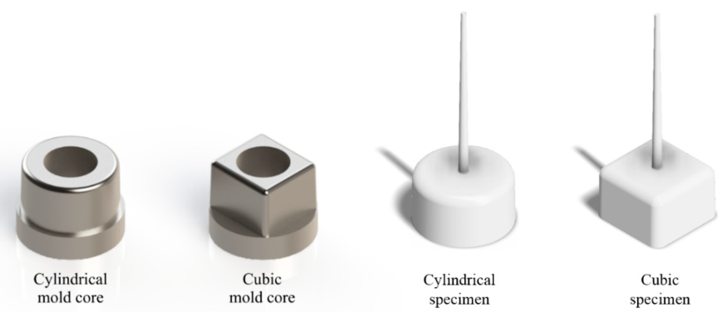
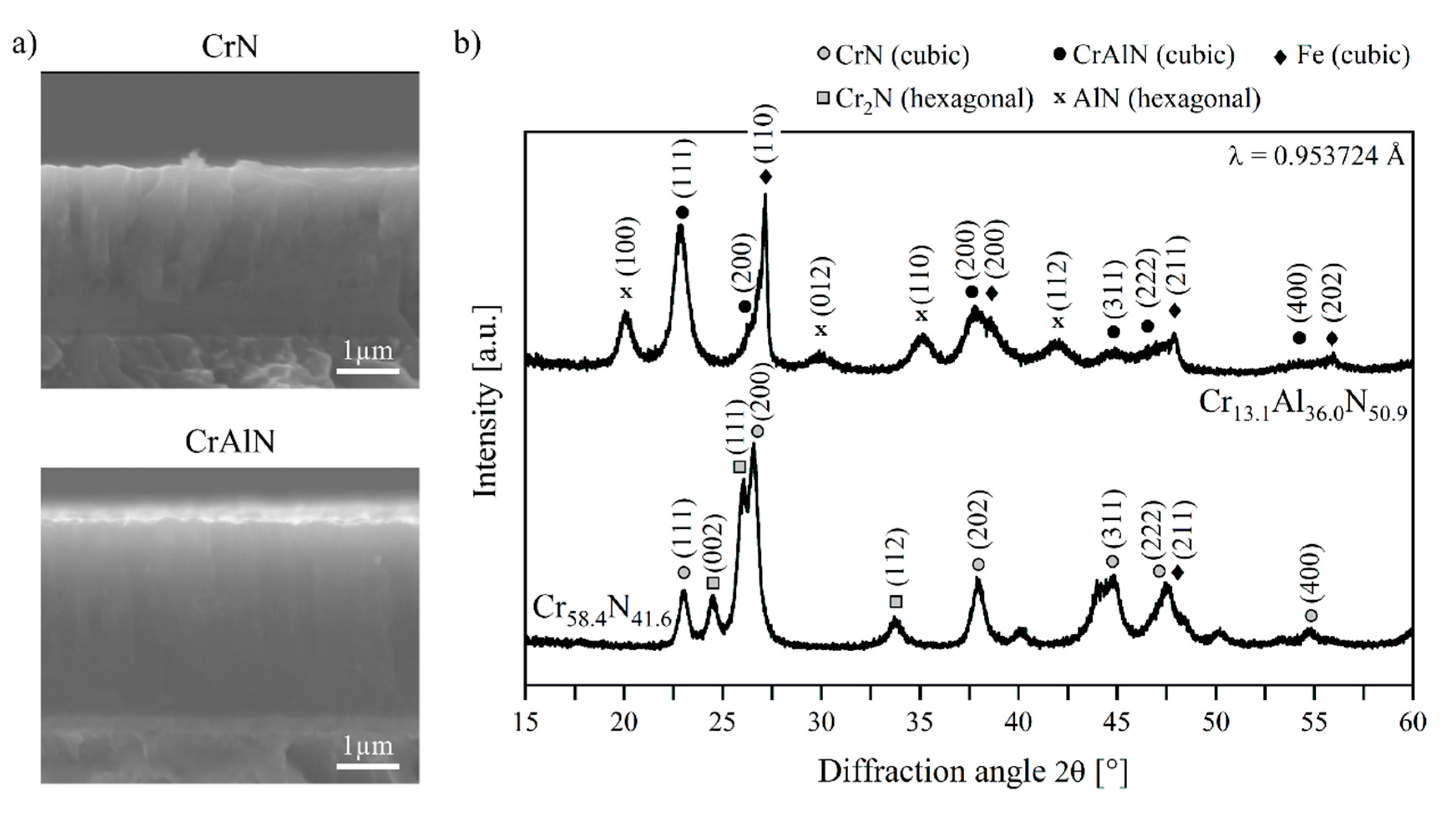
2.1. Mold Core Geometries and Deposition of CrN and CrAlN Films

Heat treated AISI H11 steel was used for the mold cores as it is widely used, due to its high toughness, high-temperature strength, and high thermal shock resistance, as a tool steel for injection molds in plastics processing [25]. A cylindrical and quadratic geometry were chosen for the mold cores in order to compare the ejection behavior of the uncoated as well as the CrN and CrAlN coated mold cores. The cylindrical core has a 36 mm diameter at the bottom and a height of 20 mm. The quadratic mold has an upper site with 29.3 × 29.3 mm2 and is also 20 mm high. The recommended draft angle to ensure the demolding of the molded part is material-specific and usually ranges from 0.5° to 3° for plastics [26]. In this case, a draft angle of 1° was applied on the mold cores. The corners and edges were rounded with a radius of 2 mm. Both mold cores had a clearance hole of 20.0 mm for the ejector pin. The cylindrical specimen geometry was used to exclude the influence of the shrinkage behavior of a box-shaped component on the ejection forces measured in this contribution. In order to compare the results, the core geometries were adjusted to a contact surface area of ~2000 mm2 between the ejected specimen and core, since the contact area affects the magnitude of the ejection force. An injection mold with a single cavity and a conical cold runner was used to produce the injection molding components. A wall thickness of 2 mm was provided for both specimen geometries in order to ensure a comparable shrinkage potential of the components. Figure 1 shows the geometry of the mold cores and specimens used. The cylindrical core was manufactured by turning, while the quadratic core was milled. After being machined, the cores were quenched and tempered to a hardness of 7.0 ± 0.3 GPa and sequentially wet barrel finished, using ceramic grinding media for 6 h.
The deposition of the CrN and CrAlN films was carried out by using the industrial magnetron sputtering device CC800/9 Custom (CemeCon AG, Würselen, Germany). Two Cr targets and two AlCr20 targets, consisting of aluminum and 20 chromium plugs, each with a target size of 500 × 88 mm2, were mounted on the cathodes. For the CrN deposition, the Cr targets were operated with a cathode power of 4 kW and the substrate holder was biased with a voltage of −90 V. Ar and Kr were used as process gases and injected with a flow rate of 300 and 50 sccm into the chamber. The flow rate of N was set to 50 sccm and the working pressure of 400 mPa was N controlled. For the CrAlN deposition, the AlCr20 targets were powered with 5 kW and a bias voltage of −120 V was applied on the substrate holder. In this case, the flow rate of Ar, Kr, and N was set to 120, 80, and 300 sccm. The working pressure was 500 mPa and N controlled. The deposition time was set to 5520 and 21,240 s for CrN and CrAlN, resulting in a film thickness of approximately 2.6 and 3.0 µm, respectively.
The chemical composition was determined to be 58.4 at.-% Cr and 41.6 at.-% N for CrN and 13.1 at.-% Cr, 36.0 at.-% Al, and 50.9 at.-% N for CrAlN by using the energy dispersive X-ray spectroscopy (EDS) with the silicon drift detector x-act (Oxford Instruments, Abingdon, UK). In x-ray diffraction experiments at the beamline BL9 of the synchrotron radiation source DELTA [27], the phase composition was identified to be the dominant cubic CrN and hexagonal Cr2N for the CrN film as well as the dominant cubic CrAlN and hexagonal AlN for the CrAlN film. Figure 2 shows the morphological structure and phase composition of the CrN and CrAlN films. It is worthwhile to mention that the Fe reflections origin from the AISI H11 substrate. In nanoindentation tests using a Berkovich diamond tip in continuous stiffness mode, the hardness values of 20.6 ± 1.9 GPa for CrN and 21.7 ± 1.9 GPa for CrAlN were measured.
In general, the PVD deposition of nitridic monolayers results in an increase of the surface roughness due to the crystalline growth and locally spread defects [28,29]. In order to investigate the influence of the PVD films on the ejection forces of PP, a comparable surface condition to the uncoated cores needs to be considered. For this reason, the coated surfaces were mechanically post-treated with diamond grains D126 with a grain size of 106 to 125 µm for approximately 15 min. The carrier material consisted of a polyurethane foam with a thickness of 1.5 mm, which was bonded to a steel sheet. The cutting speed was set to 50 m/min and a pressure force of 10 ± 2 N was applied.

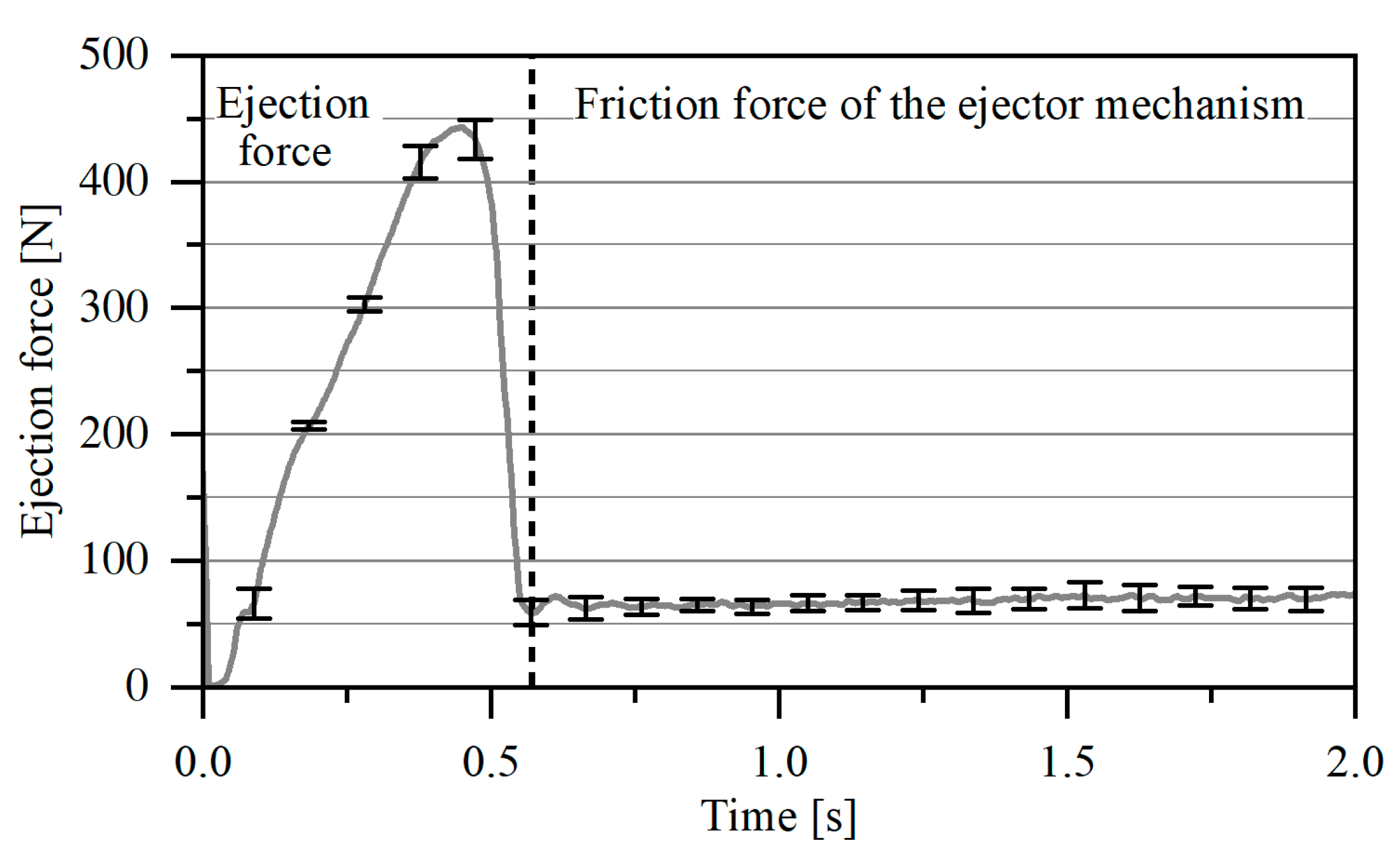
2.2. Surface Characterization of Coated Cores and Injection Molding Experiments

The surface roughness of the CrN and CrAlN coated molds was analyzed by employing the confocal 3D microscope µsurf (NanoFocus, Oberhausen, Germany). The roughness analysis was carried out according to ISO 4287 and ISO 4288. Within this context, the roughness profiles Ra, Rz, Rk, and Rpk were determined in order to have a broader base of roughness parameters. In addition, the topography was investigated by scanning electron microscopy (SEM) using a FE-JSEM 7001 (Jeol, Akishima, Japan).
The ejection force measurements were carried out with the injection molding machine Allrounder 270 S (Arburg, Lossburg, Germany). The molding cores were mounted on the molding plate. The measuring system consisted of a load cell, which was placed between the ejector bolt and ejector plate. The demolding was carried out by an ejector pin, which was attached to the ejector plate and pierced through the center of the molding cores. This setup was chosen as it was simple to realize, but it needs to be taken into account that the entire system friction of the ejector plate and ejector pin as well as their mass inertia contribute to the measured force and thus need to be taken into consideration as well. A semi-crystalline PP with a MFR value of 7.5 g/10 min is used for the injection molding tests. The processing parameters were adjusted according to the manufacturer’s specifications for the respective plastic and are summarized in Table 1.
The force-time curves were measured during the ejection. Figure 3 shows the characteristic force-time curve during the demolding step. Within this context, the distance is calculated by multiplying the demolding time and ejector speed. It can be clearly observed that the measured force signal consists of the initial demolding process and a constant force component resulting from the inner friction of the entire ejector system. The experiments were evaluated by determining the maximum of the ejection force. In this regard, the system-related force component was determined with a reference cycle without injecting the plastic in order to subtract the value from the measured ejection force. For each core variant, a total amount of 50 injection molding cycles were carried out successively to calculate the average value of the ejection force. The data acquisition was started after reaching a stable operating state of the system to avoid an influence of start-up effects on the measurements.

3. Results and Discussion

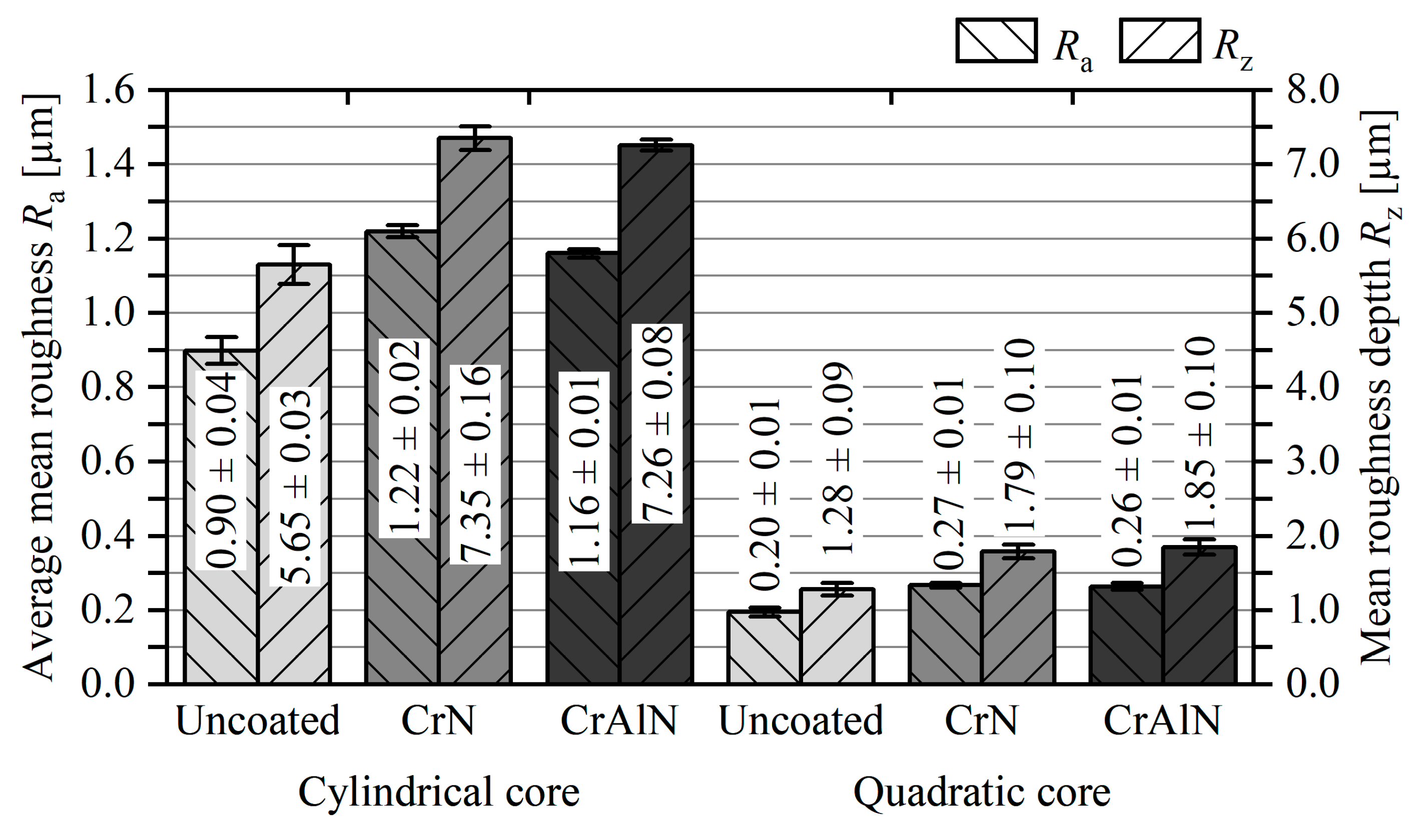
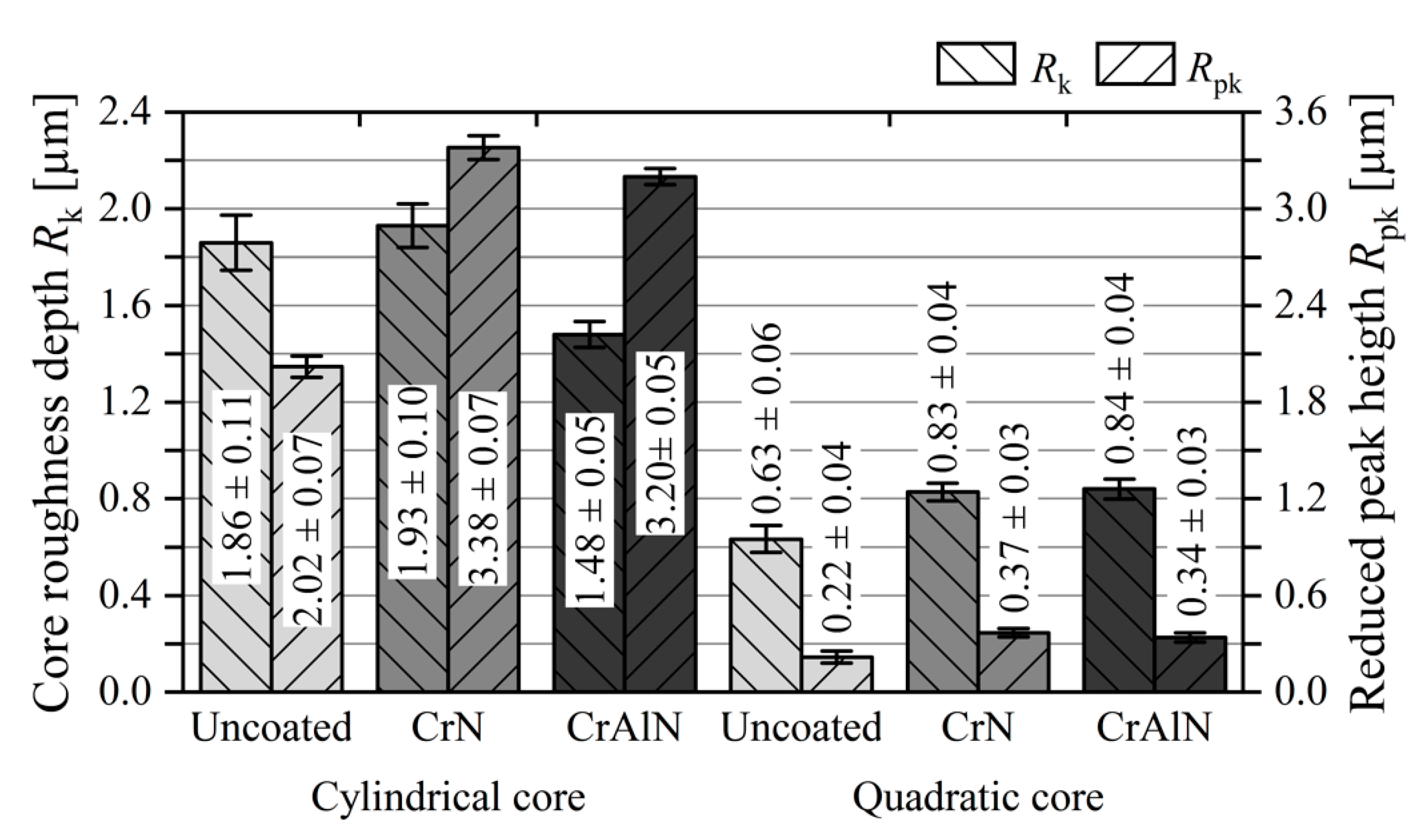
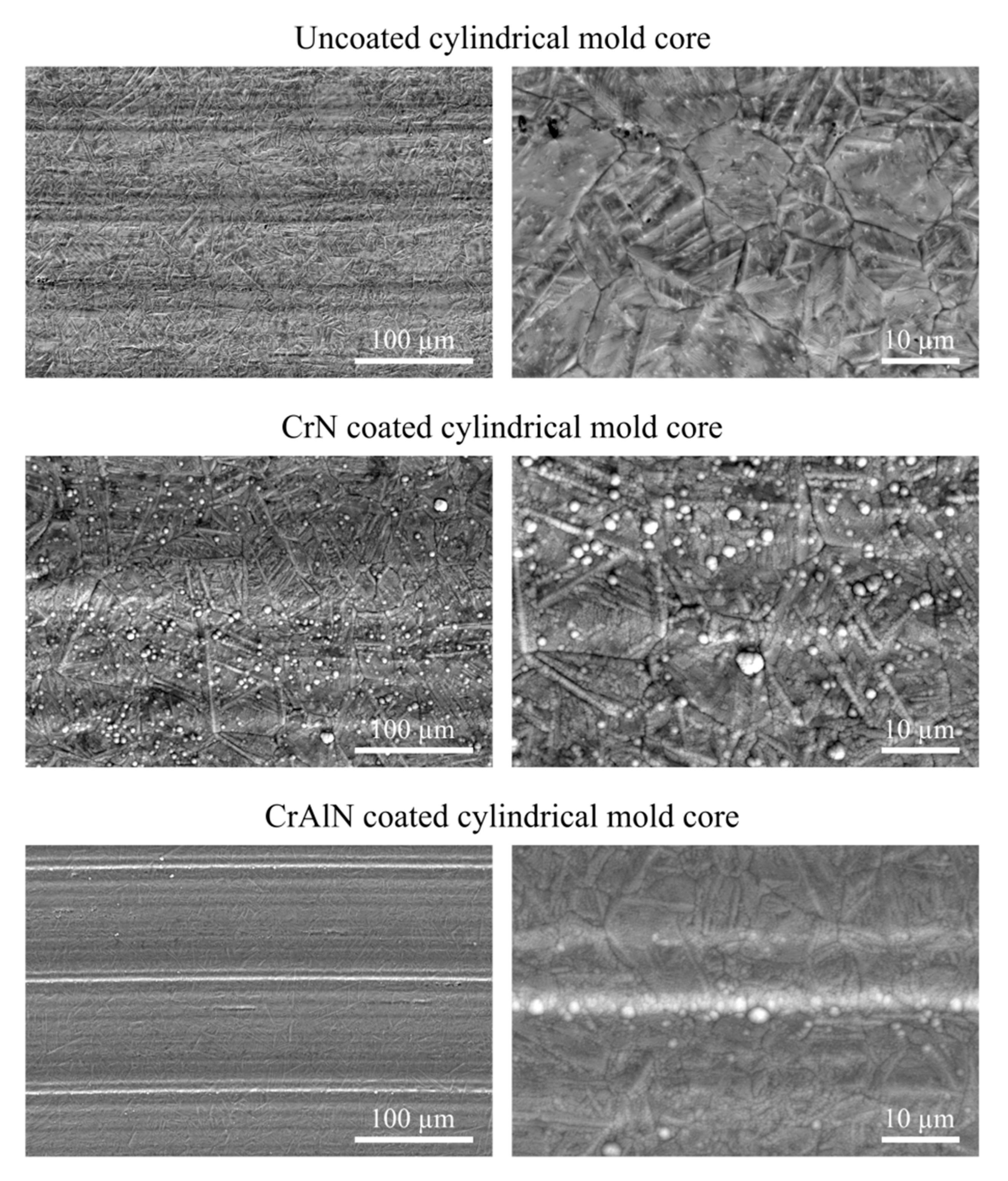
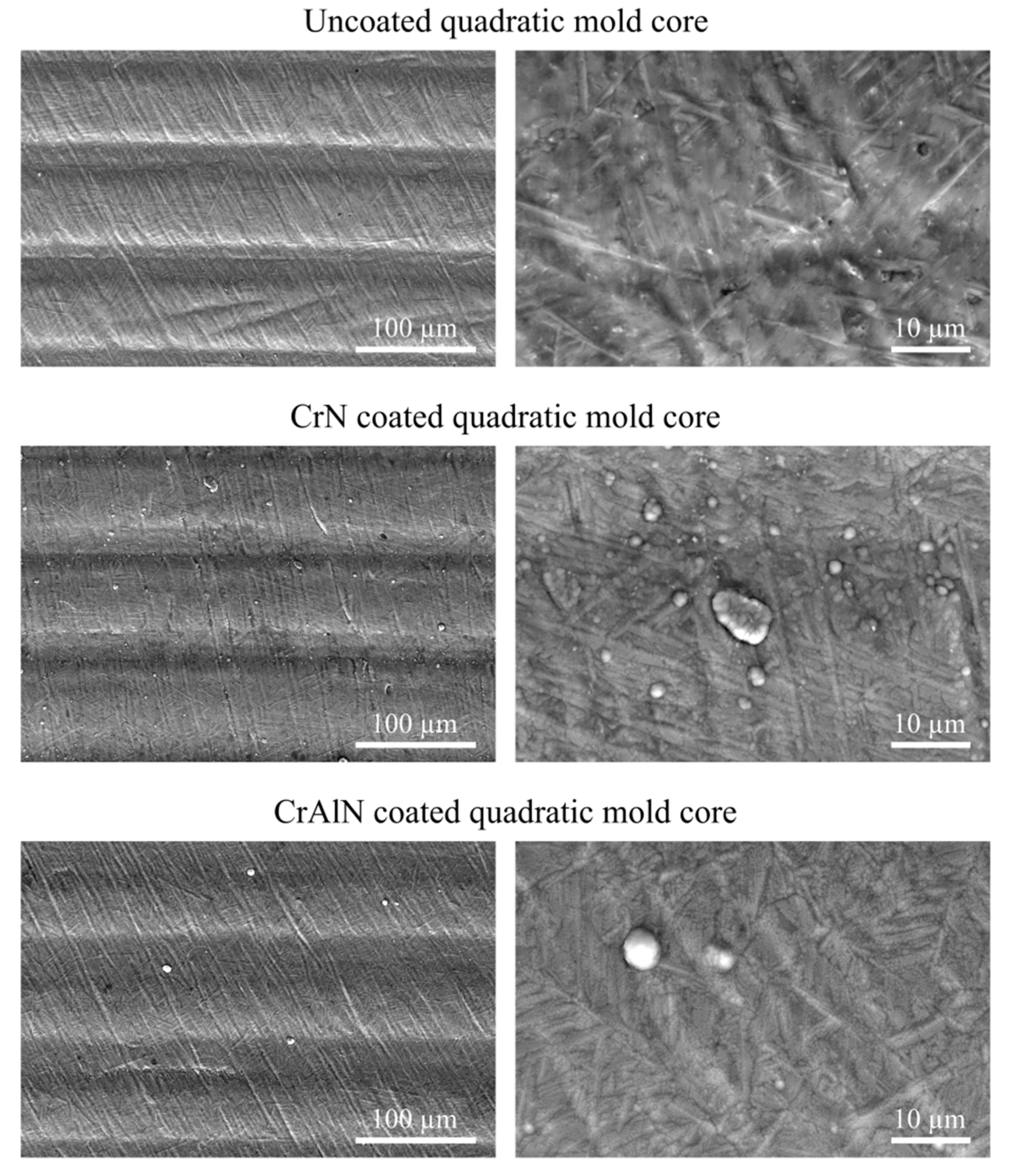
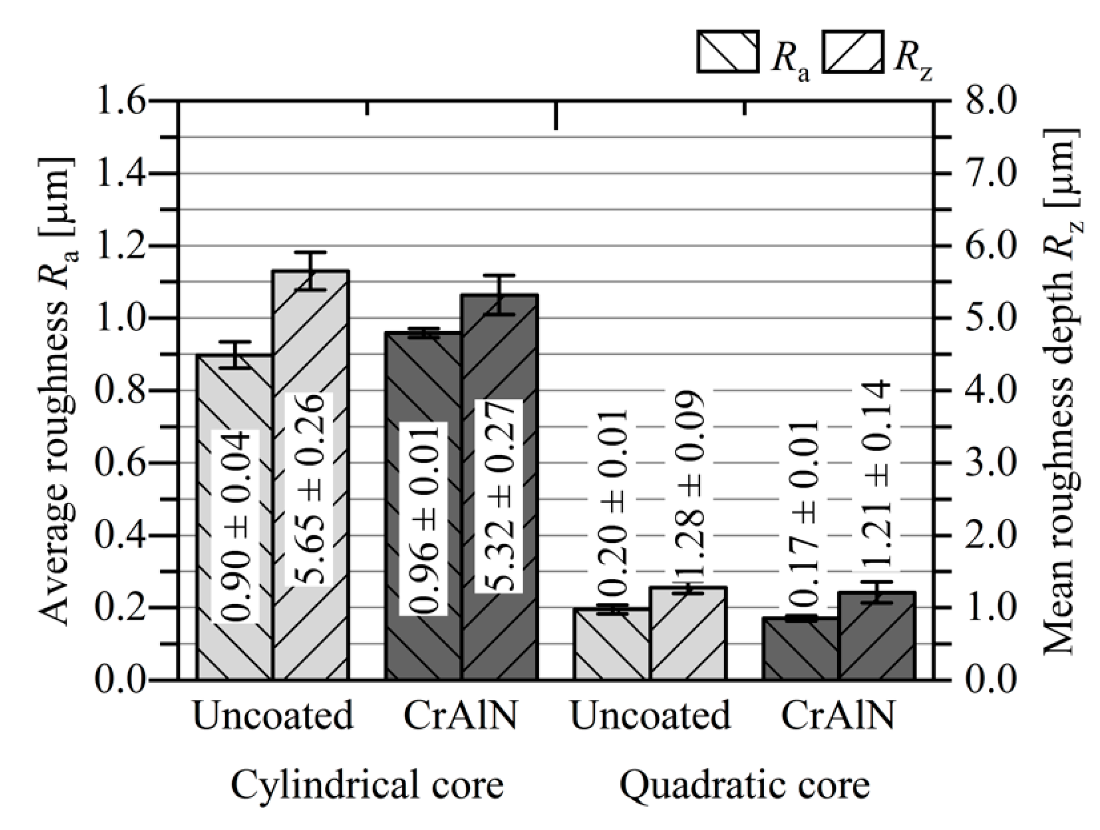
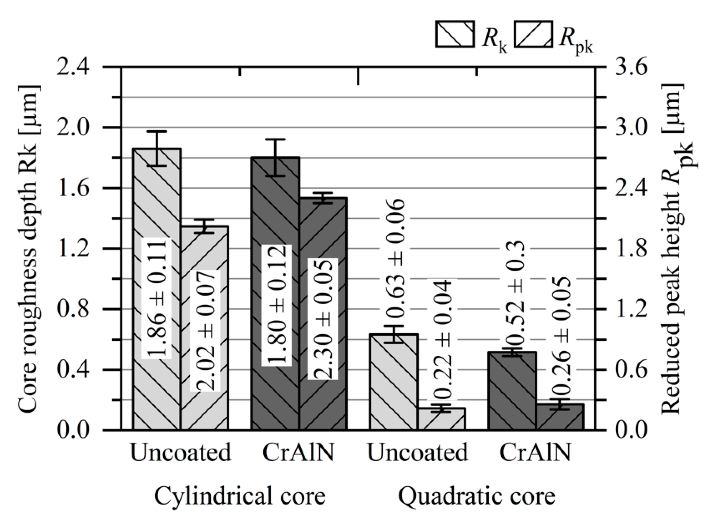
3.1. Surface Roughness of the Coated Cores without a Mechanical Post-Treatment

The topography of the uncoated and as-deposited coated mold cores was analyzed by determining the roughness parameters using a confocal 3D microscope. The average mean roughness Ra, mean roughness depth Rz, core roughness depth Rk, and reduced peak height Rpk are visualized in Figure 4 and Figure 5. In addition, SEM analyses of the topography of the cylindrical and quadratic core in each surface condition were conducted (see Figure 6 and Figure 7). It is noted that the quadratic cores are marked by a lower surface roughness when compared to the roughness of the cylindrical cores. In case of the uncoated cores, the cylindrical core has a Ra = 0.90 ± 0.04 µm and Rz = 5.65 ± 0.03 µm, while the quadratic variant has lower values of Ra = 0.20 ± 0.01 µm and Rz = 1.28 ± 0.09 µm. A similar behavior is also observed for the roughness parameters Rk and Rpk. The different surface topographies of the cylindrical and quadratic cores are ascribed to the different machining techniques used to process the cores. Due to the geometry, the cylindrical core was manufactured by turning and the quadratic core by milling. The machining techniques are distinguished by different cutting mechanisms, thus leading to different surface finishes. The distinctive topographical structures of the cylindrical and quadratic core are clearly visible on the SEM micrographs. In general, the deposition of the CrN and CrAlN films lead to a roughness increase for both mold geometries [24,30,31,32]. This behavior is typical for the deposition of nitridic monolayers, since roughness asperities disturb the direct trajectory of impinging sputtered materials and generate a shadow for the homogenous film growth [29]. This so-called shadow effect results in film growth defects and consequently in a roughness increase [28]. The formation of such growth defects is clearly notable on SEM micrographs at higher magnification for both the cylindrical and quadratic mold cores. For the cylindrical cores, the deposition of the CrN film leads to a roughness increase with values of Ra = 1.22 ± 0.02 µm and Rz = 7.35 ± 0.16 µm, while CrAlN results in values of Ra = 1.16 ± 0.01 µm and Rz = 7.26 ± 0.08 µm. In case of the quadratic molds, the CrN coated cores have a roughness of Ra = 0.27 ± 0.01 µm and Rz = 1.79 ± 0.10 µm, whereas the CrAlN variant has values of Ra = 0.26 ± 0.01 µm and Rz = 1.85 ± 0.10 µm. A roughness increase of the PVD coated cores are also noted for the roughness parameters Rk and Rpk.

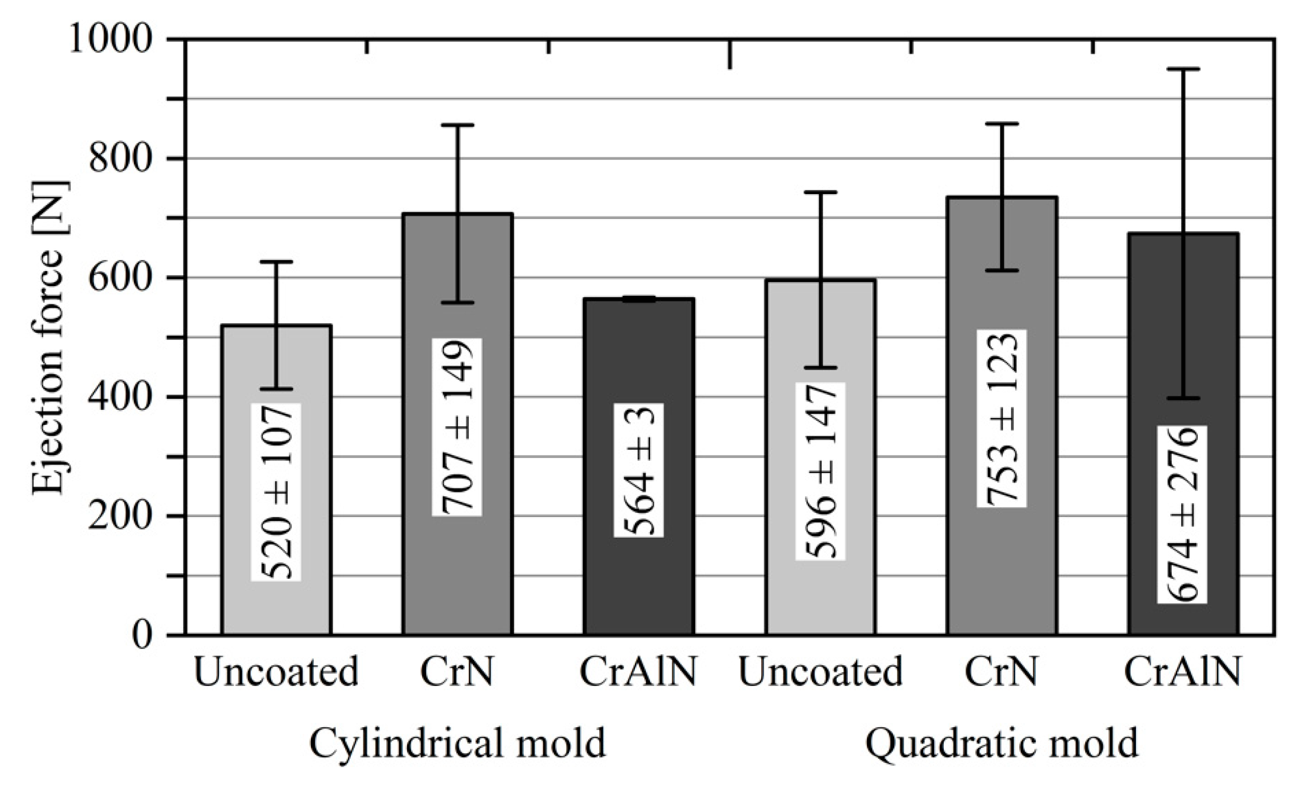
3.2. Ejection Forces of Coated Cores without a Mechanical Post-Treatment

The maximum ejection forces when demolding the PP parts from the uncoated and coated cores are shown in Figure 8. It is noted that the cylindrical cores exhibit lower ejection forces compared to the quadratic cores. This fact is mainly attributed to the different shrinkage behavior of the molded part on the mold cores and the different roughness profiles. The shrinkage of the molded PP part results in higher contact pressures at the edges and corners, whereas the contact pressure is homogenously distributed onto the cylindrical core. Moreover, the cylindrical cores have a higher surface roughness than the quadratic variant. The higher roughness favors an increase of the deformative friction component. The roughness asperities hinder the sliding and plough the softer counterpart during the ejection process, thus leading to a higher friction. Both mechanisms need to be taken into account when comparing the ejection behavior of the mold cores with different geometries.
With regard to the coated cores, CrN and CrAlN have an identical impact on the ejection forces. The CrN coated cylindrical core shows an ejection force of 707 ± 149 N, whereas the CrAlN coated mold exhibits a lower value of 564 ± 3 N. In case of the quadratic cores, a similar relation is observed when considering only the mean values of the ejection forces. The CrN and CrAlN coated cores with a quadratic geometry are marked by an ejection force of 753 ± 123 and 674 ± 276 N. However, the coated cores are marked by higher ejection forces than the uncoated variant. Among the different surface systems, the uncoated cylindrical and quadratic mold cores exhibit the lowest ejection forces of 520 ± 107 and 596 ± 147 N when compared to the as-deposited CrN and CrAlN coated cores.

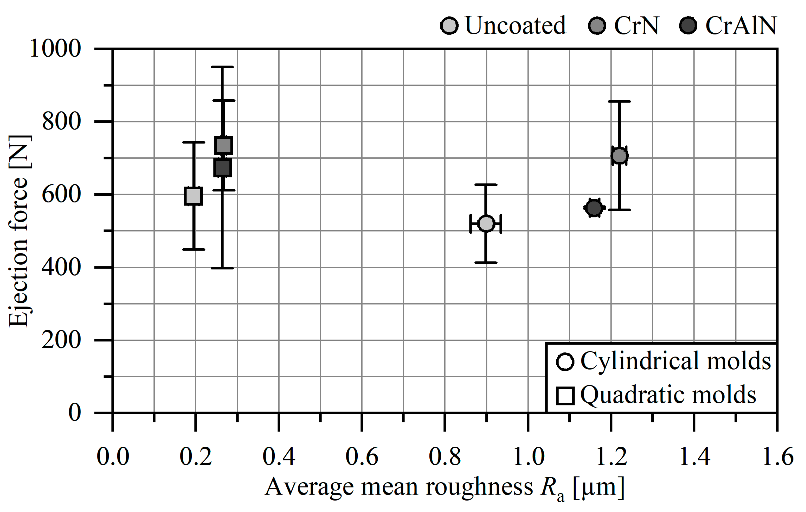
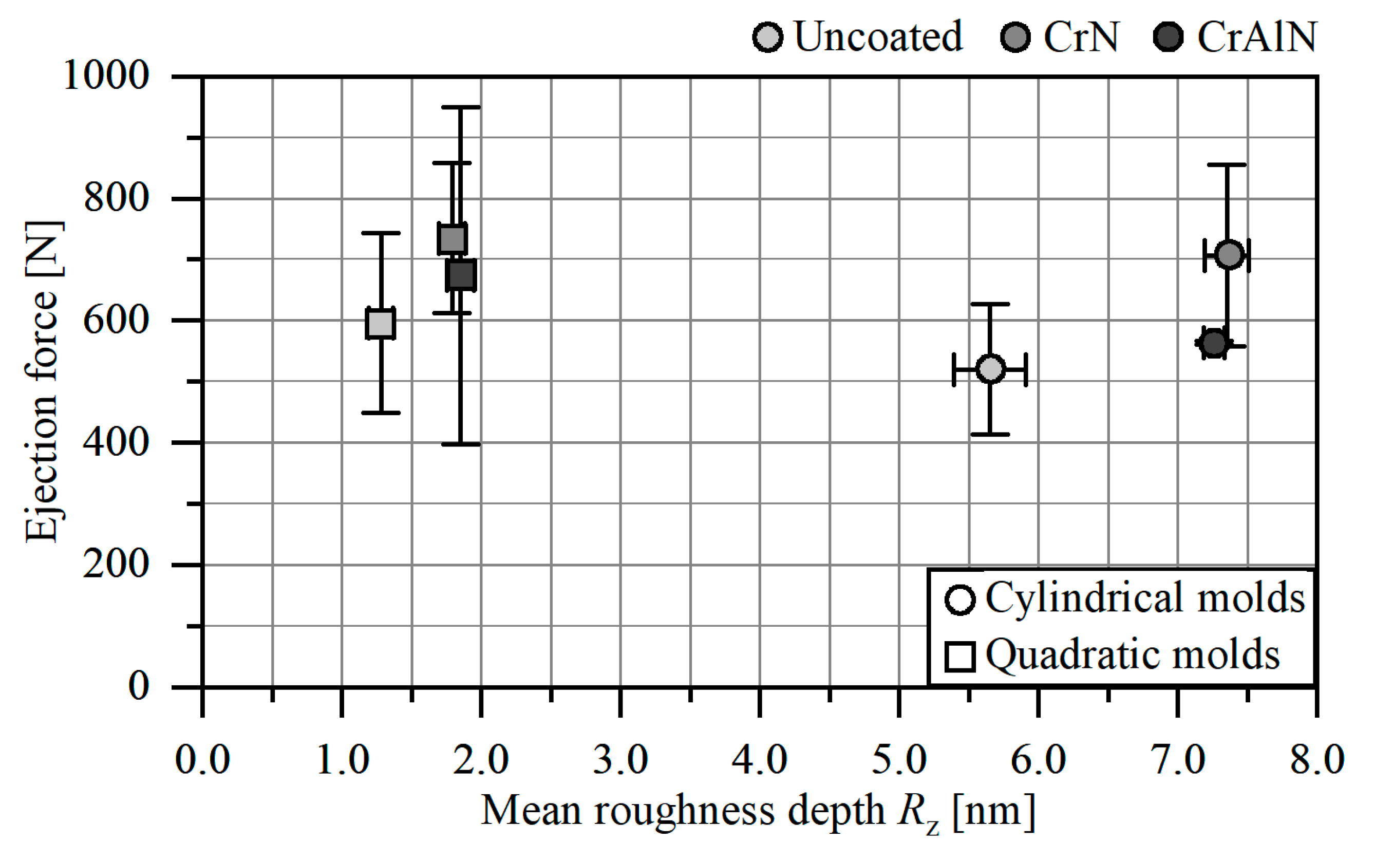
3.3. Influence of the Surface Roughness on the Ejection Forces

The different roughness profiles of the cylindrical and quadratic cores need to be considered for the ejection behavior, since the roughness asperities lead to an increase of the deformative friction component [7]. According to Sorgato et al., the molten plastic part replicates the mold topography during the filling, so that roughness asperities result in a mechanical interlocking between mold surface and processed plastic part [22]. As a consequence, a higher force is required to overcome the deformative friction component in order to initiate a sliding of the solidified plastic part. Therefore, the as-deposited CrN and CrAlN mold cores are marked by a rougher surface with distinctive roughness asperities, which result in a higher deformative friction component. This behavior is particularly noted when plotting the ejection forces against the surface roughness. Figure 9 shows ejection forces plotted against the roughness parameter Ra. For the cylindrical and quadratic cores, it is noted that the ejection force increases at higher Ra values. A similar behavior is observed for the roughness parameter Rz in Figure 10 as well as Rk and Rpk (not shown here). The influence of the roughness profile on the ejection force was already investigated in several works. Sasaki et al. varied the arithmetical mean roughness Ra from 0.016 to 0.689 µm for uncoated cylindrical cores and measured the ejection forces when demolding PP, polymethyl methacrylate (PMMA), and polyethylene terephthalate (PET) parts [19]. They noted that the ejection force increases with an increasing roughness Ra from 0.092 to 0.689 µm and ascribed this fact to the higher deformative friction caused by the roughness asperities. However, they measured the highest ejection force for the mold with the lowest roughness Ra of 0.016 µm and suggested that the adhesive friction mechanism contributes to higher ejection forces at lower surface roughness values. A similar influence of the roughness on the ejection force of molded PP parts was further noted by Pontes et al. [33]. In contrast, Chen et al. analyzed the adhesion behavior of CrN and DLC coated cores with a varying roughness Ra from 0.010 to 0.080 µm by using a specially designed adhesion force tester [34]. At these low Ra values, they noted that the adhesion force decreases for CrN and DLC films with a higher surface roughness and assigned this behavior to the lower adhesion. According to Pouzada et al., a region of an optimal surface roughness of the core favors the reduction of the ejection force [6]. Therefore, it can be concluded that a deposition of CrN and CrAlN films leads to a roughness increase, which contributes to a higher deformative friction component and consequently to higher ejection forces.

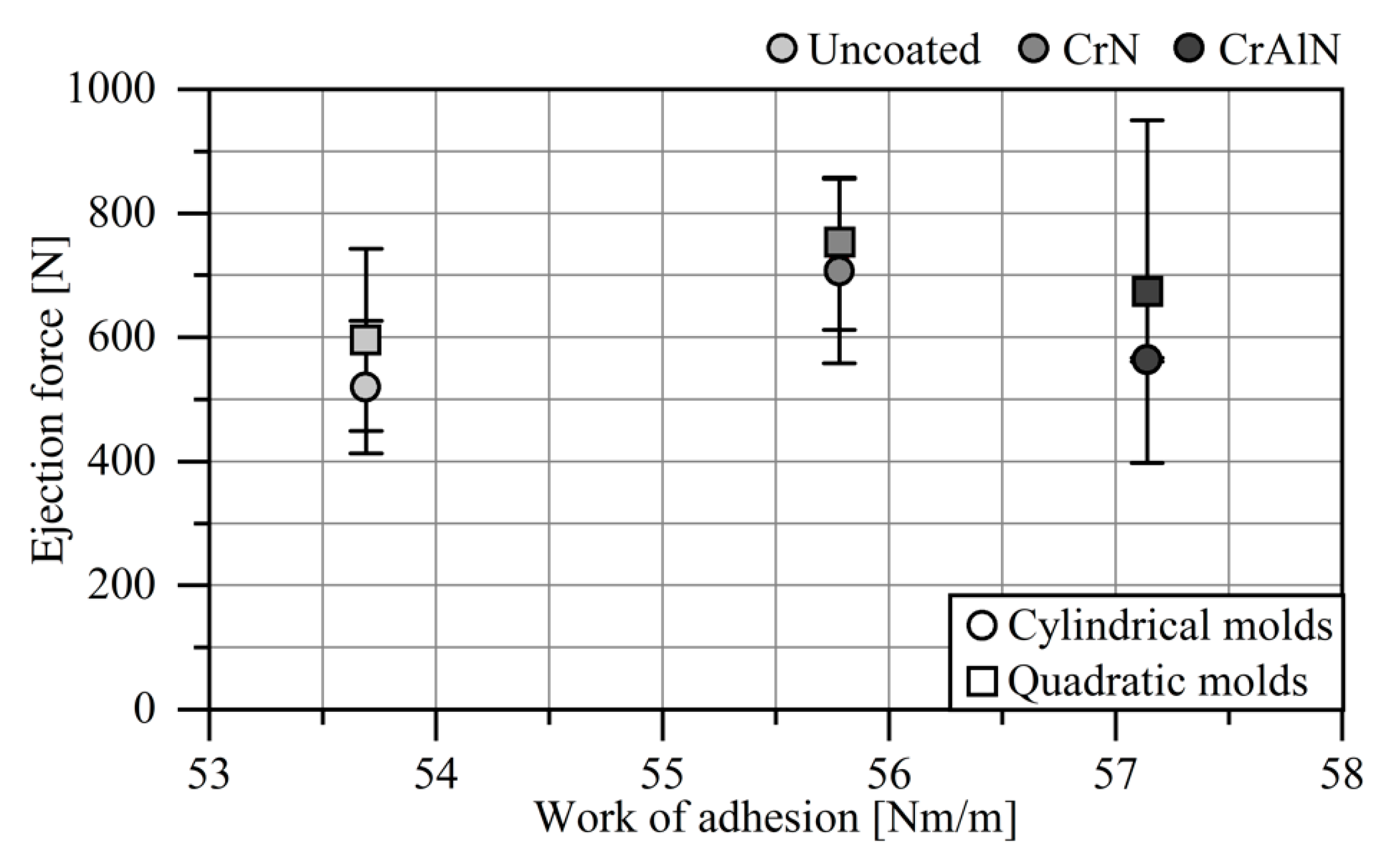
3.4. Influence of the Adhesion Behavior on the Ejection Forces

Besides the deformative friction component, the adhesive friction has also a significant influence on the magnitude of the ejection force. However, determining the adhesive friction component is highly challenging and difficult to implement in real applications. In a more theory-based approach, the work of adhesion of CrN, CrAlN, and uncoated AISI H11 with PP was determined [24]. For this purpose, surface energies as well as disperse and polar components were determined in contact angle measurements and used to calculate the work of adhesion. Within this context, the AISI H11 substrate has the lowest work of adhesion of 53.4 mN/m, while the CrN and CrAlN films exhibit slightly higher values of 55.8 and 57.1 mN/m. For polycarbonate (PC) and PMMA, Bobzin et al. observed a lower wettability for CrAlN against the plastic melts in comparison to uncoated AISI H11 [35]. Figure 11 shows the plot of ejection forces against the work of adhesion with PP. For the uncoated cores, it is noted that a low work of adhesion favors low ejection forces. In contrast, the CrN and CrAlN films have higher works of adhesion and consequently exhibit higher ejection forces. However, this relation is not linear, as the CrAlN film is marked by a higher work of adhesion with lower ejection forces when compared to CrN. On the one hand, the range of the work of adhesion of the three surface conditions is very narrow, so that the adhesion does not have a significant impact. On the other hand, the surface roughness is too high, so that the adhesive friction mechanism is less decisive for the magnitude of the ejection force, whereas the deformative friction component is the dominant mechanism.

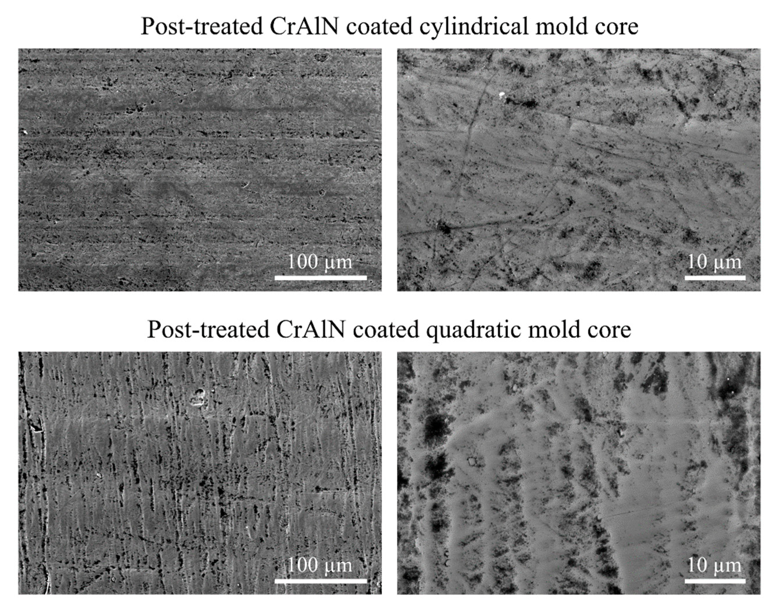
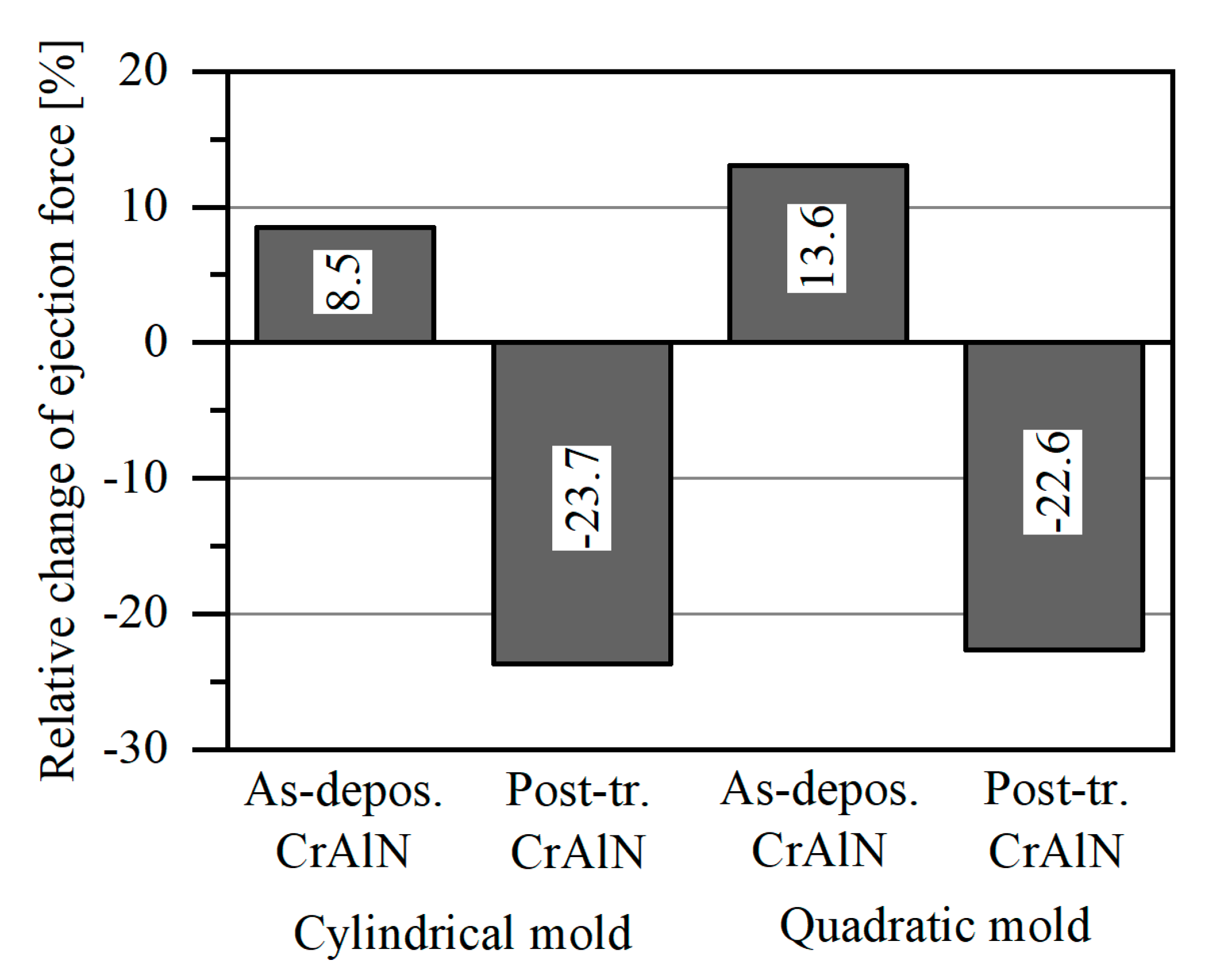
3.5. Ejection Forces of Mechanically Post-Treated CrAlN Coated Cores

In order to be able to compare the PVD coated core surfaces with the uncoated reference, a mechanical post-treatment of the PVD films is necessary to reduce the surface roughness. For this purpose, the CrAlN coated cores are considered, as they exhibit lower ejection forces when compared to the CrN coated cores. The mechanical post-treatment of the surfaces successfully reduces the roughness to comparable values. The roughness parameters Ra, Rz, Rk, and Rpk of the mechanically post-treated CrAlN cores are shown in Figure 12 and Figure 13. It is clearly visible that the post-treated CrAlN coated cores exhibit comparable roughness values. Due to the post-treatment, the CrAlN coated cylindrical core has lower roughness values of Ra = 0.96 ± 0.01 µm and Rz = 5.32 ± 0.27 µm. The post-treated CrAlN coated quadratic core has also lower values of Ra = 0.17 ± 0.01 µm and Rz = 1.21 ± 0.14 µm. Lower values are also observed for the roughness parameters Rk and Rpk. The roughness reduction of the CrAlN coated cores is ascribed to the removal of the growth defects, as the SEM micrographs show in Figure 14. Moreover, it is visible that the surface of the post-treated coated surfaces is smoother.
After adjusting the roughness to a similar surface quality as the uncoated cores, the mechanically post-treated CrAlN cores were mounted in an injection molding machine to determine the change of the ejection forces in comparison to the uncoated cores. Within this context, lower ejection forces were observed for the post-treated CrAlN coated cores. Figure 15 shows the relative change of the ejection forces of the as-deposited and post-treated CrAlN cores in comparison to the ejection forces of the uncoated cores. It can be noted that the ejection forces of the CrAlN coated cylindrical and quadratic cores are reduced to values by −23.7% and −22.6%. This behavior is ascribed to the reduction of the roughness asperities, which ensure an interlocking between the mold surface and plastic part. By weakening this interlocking mechanism, the required force to initiate the sliding of the plastic part is reduced and the magnitude of the adhesive friction component is more decisive for the ejection force. Consequently, a post-treatment of PVD coated cores with a low adhesion against PP is essential in order to reduce the ejection force in injection molding processes.

4. Conclusions and Outlook

CrN and CrAlN films were deposited on cylindrical and quadratic AISI H11 mold cores by means of direct current magnetron sputtering to investigate the effect of the Cr-based nitrides on the ejection force when demolding PP parts from the core. Regardless of the core geometry, an identical influence of the surface condition on the ejection force was observed. Within this context, CrN and CrAlN films exhibited higher ejection forces than the uncoated AISI H11 core. This behavior is ascribed to the roughness increase resulting from the PVD deposition, which leads to an increase of the deformative friction. Since the surface roughness of the cores play a significant role for the deformative friction mechanism, a subsequent treatment of the PVD coated surfaces is essential to minimize the roughness and, consequently, to reduce the ejection forces. A promising attempt to adjust the roughness profile of PVD coated cores is achieved by a proper post-surface treatment. Within this context, a polishing strategy was successfully employed to reduce the surface roughness of CrAlN coated cores to comparable values as obtained by the uncoated cores. The post-treatment of the CrAlN coated surfaces ensured a reduction of the ejection forces by 23.7% and 22.6% for the cylindrical and quadratic cores. Therefore, a combination of the deposition of a CrAlN film and a subsequent post-surface treatment has proven to be an auspicious approach to reduce the ejection forces in injection molding processes.
To reduce the effort for the post-treatment process in further investigations, a smart pre-treatment strategy should be considered, such as for example micromilling. By micromilling high-speed tool steel, it is possible to obtain a surface finish with very low Ra values down to 20 nm [36]. Hence, micromilling can be used to locally adjust the friction condition of surface areas under high contact pressure applied by the shrinkage. Using micromilled surface structures have proven to be a suitable approach to adjust the friction condition [37]. If the adhesive friction mechanism is considered, the magnitude of the force that breaks the bonds between the mold surface and molded plastic is strongly affected by the pairing of PVD film and plastic part. Therefore, further investigations, concerning the adhesion behavior of different PVD films with diverse plastic materials, need to be carried out in order to identify pairings with a low adhesion. In conclusion, the consideration of the deformative and adhesive friction component is fundamental to understand the interaction mechanisms during the ejection of the molded plastic components.

Author Contributions

Conceptualization, W.T., D.S., N.F.L.D., N.G., M.S. (Michael Stanko), M.S. (Markus Stommel), E.K. and D.B.; methodology, D.S., N.F.L.D., N.G., M.S. (Michael Stanko), and E.K.; investigation, D.S., N.F.L.D., M.S. (Michael Stanko) and E.K.; writing—original draft preparation, N.F.L.D., M.S. (Michael Stanko) and E.K., writing—review and editing, W.T., D.S., M.S. (Markus Stommel) and D.B.; visualization, N.F.L.D.; supervision, W.T., M.S. (Markus Stommel) and D.B.

Funding

This research received no external funding.

Acknowledgments

The authors acknowledge the financial support by the German Research Foundation and TU Dortmund University within the funding program “Open Access Publishing”. Furthermore, the authors wish to express their gratitude to the DELTA machine group for providing the synchrotron radiation at BL9.

Conflicts of Interest

The authors declare no conflict of interest.

References

  1. Zheng, R.; Tanner, R.I.; Fan, X.-J. Injection Molding: Integration of Theory and Modeling Methods; Springer: Berlin/Heidelberg, Germany, 2011; ISBN 978-3-642-21262-8. [Google Scholar]
  2. Gramann, P.J.; Osswald, T.A. Introduction. In Injection Molding Handbook, 2nd ed.; Osswald, T.A., Turng, L.-S., Gramann, P.J., Eds.; Hanser: Munich, Germany; Cincinnati, OH, USA, 2008; pp. 1–18. ISBN 978-3-446-40781-7. [Google Scholar]
  3. Sakai, T.; Kikugawa, K. Injection Molding Machinery and Systems. In Injection Molding: Technology and Fundamentals; Kamal, M.R., Agassant, J.-F., Eds.; Hanser: Munich, Germany, 2009; pp. 73–131. ISBN 978-3-446-41685-7. [Google Scholar]
  4. Kazmer, D. Injection Mold Design Engineering, 2nd ed.; Hanser Publications: Munich, Germany; Cincinnati, OH, USA, 2016; ISBN 978-1-56990-570-8. [Google Scholar]
  5. Osswald, T.A. Processing Fundamentals. In Injection Molding Handbook, 2nd ed.; Osswald, T.A., Turng, L.-S., Gramann, P.J., Beaumont, J., Eds.; Hanser: Munich, Germany; Cincinnati, OH, USA, 2008; pp. 63–124. ISBN 978-3-446-40781-7. [Google Scholar]
  6. Pouzada, A.S.; Ferreira, E.C.; Pontes, A.J. Friction properties of moulding thermoplastics. Polym. Test. 2006, 25, 1017–1023. [Google Scholar] [CrossRef] [Green Version]
  7. Delaney, K.D.; Bissacco, G.; Kennedy, D. A Structured Review and Classification of Demolding Issues and Proven Solutions. IPP 2012, 27, 77–90. [Google Scholar] [CrossRef]
  8. Štěpek, J.; Daoust, H. Lubricants and Mold-Release Agents. In Additives for Plastics; Štěpek, J., Daoust, H., Eds.; Springer: New York, NY, USA, 1983; pp. 34–49. ISBN 978-1-4612-6417-0. [Google Scholar]
  9. Percell, K.S.; Tomlinson, H.H.; Walp, L.E. Nonmetallic Fatty Chemicals as Internal Mold Release Agents in Polymers. In Coatings Technology Handbook, 3rd ed.; Tracton, A.A., Ed.; CRC Taylor & Francis: Boca Raton, FL, USA, 2006; pp. 573–580. ISBN 9781574446494. [Google Scholar]
  10. Tölke, T.; Keil, D.; Marschner, C.; Homuth, M.; Pfuch, A.; Matthes, G.; Hering, W.; Grünler, B. Sol-Gel-coatings—Versatile possibilities for surface functionalization. Galvanotechnik 2015, 9, 1848–1854. [Google Scholar]
  11. Yamamoto, H.; Ohkubo, Y.; Ogawa, K.; Utsumi, K. Application of a chemically adsorbed fluorocarbon film to improve demolding. Precis. Eng. 2009, 33, 229–234. [Google Scholar] [CrossRef]
  12. Yamamoto, H.; Ohkubo, Y.; Ogawa, K.; Utsumi, K. Physical performance of the metal surface covered with the highly durable and chemically adsorbed fluorocarbon film. Precis. Eng. 2010, 34, 440–445. [Google Scholar] [CrossRef]
  13. Hopmann, C.; Pauling, A.; Holz, C.; Vissing, K. Investigations on a plasma polymeric mould coating for the release agent-free demoulding of PU-parts. J. Plast. Technol. 2014, 5, 166–187. [Google Scholar]
  14. Mori, K.; Sasaki, Y.; Hirahara, H.; Oishi, Y. Development of polymer-molding-releasing metal mold surfaces with perfluorinated-group-containing polymer plating. J. Appl. Polym. Sci. 2003, 90, 2549–2556. [Google Scholar] [CrossRef]
  15. Crisan, N.; Descartes, S.; Berthier, Y.; Cavoret, J.; Baud, D.; Montalbano, F. Tribological assessment of the interface injection mold/plastic part. Tribol. Int. 2016, 100, 388–399. [Google Scholar] [CrossRef]
  16. Silva, F.; Martinho, R.; Andrade, M.; Baptista, A.; Alexandre, R. Improving the Wear Resistance of Moulds for the Injection of Glass Fibre–Reinforced Plastics Using PVD Coatings: A Comparative Study. Coatings 2017, 7, 28. [Google Scholar] [CrossRef]
  17. Silva, F.J.G.; Martinho, R.P.; Baptista, A.P.M. Characterization of laboratory and industrial CrN/CrCN/diamond-like carbon coatings. Thin Solid Film. 2014, 550, 278–284. [Google Scholar] [CrossRef]
  18. D’Avico, L.; Beltrami, R.; Lecis, N.; Trasatti, S. Corrosion Behavior and Surface Properties of PVD Coatings for Mold Technology Applications. Coatings 2019, 9, 7. [Google Scholar] [CrossRef]
  19. Sasaki, T.; Koga, N.; Shirai, K.; Kobayashi, Y.; Toyoshima, A. An experimental study on ejection forces of injection molding. Precis. Eng. 2000, 24, 270–273. [Google Scholar] [CrossRef]
  20. Burkard, E.; Walther, T.; Schinköthe, W. Influence of Mold Wall Coatings While Demoulding in the Injection Molding Process; Stuttgarter Kunststoff-Kolloquium: Stuttgart, Germany, 1999. [Google Scholar]
  21. Martins, L.C.; Ferreira, S.C.; Martins, C.I.; Pontes, A.J. Study of ejection forces in injection moulding of thin-walled tubular mouldings. In Proceedings of the PMI 2014 International Conference on Polymers and Moulds Innovations, Guimarães, Portugal, 10–12 September 2014; pp. 281–286. [Google Scholar]
  22. Sorgato, M.; Masato, D.; Lucchetta, G. Tribological effects of mold surface coatings during ejection in micro injection molding. J. Manuf. Process. 2018, 36, 51–59. [Google Scholar] [CrossRef]
  23. Lucchetta, G.; Masato, D.; Sorgato, M.; Crema, L.; Savio, E. Effects of different mould coatings on polymer filling flow in thin-wall injection moulding. Cirp Ann. 2016, 65, 537–540. [Google Scholar] [CrossRef]
  24. Tillmann, W.; Lopes Dias, N.F.; Stangier, D.; Gelinski, N. Tribological Performance of PVD Film Systems against Plastic Counterparts for Adhesion-Reducing Application in Injection Molds. Coatings 2019, 9, 588. [Google Scholar] [CrossRef]
  25. Mitschang, P.; Schledjewski, R.; Schlarb, A.K. Molds for Continuos Fibre Reinforced Polymer Composites. In Mold-Making Handbook, 3rd ed.; Mennig, G., Stoeckhert, K., Eds.; Hanser: München, Germany, 2013; pp. 200–238. ISBN 978-1-56990-446-6. [Google Scholar]
  26. Pruner, H.; Nesch, W. Understanding Injection Molds; Hanser: München, Germany, 2013; ISBN 978-1-56990-527-2. [Google Scholar]
  27. Krywka, C.; Paulus, M.; Sternemann, C.; Volmer, M.; Remhof, A.; Nowak, G.; Nefedov, A.; Pöter, B.; Spiegel, M.; Tolan, M. The new diffractometer for surface X-ray diffraction at beamline BL9 of DELTA. J. Synchrotron Radiat. 2006, 13, 8–13. [Google Scholar] [CrossRef]
  28. Panjan, P.; Čekada, M.; Panjan, M.; Kek-Merl, D. Growth defects in PVD hard coatings. Vacuum 2009, 84, 209–214. [Google Scholar] [CrossRef]
  29. Mattox, D.M. Handbook of Physical Vapor Deposition (PVD) Processing; Elsevier: Amsterdam, The Netherlands, 2010. [Google Scholar]
  30. Löffler, M.; Schulte, R.; Freiburg, D.; Biermann, D.; Stangier, D.; Tillmann, W.; Merklein, M. Control of the material flow in sheet-bulk metal forming using modifications of the tool surface. Int. J. Mater. Form. 2019, 12, 17–26. [Google Scholar] [CrossRef]
  31. Lee, S.-C.; Ho, W.-Y.; Lai, F.D. Effect of substrate surface roughness on the characteristics of CrN hard film. Mater. Chem. Phys. 1996, 43, 266–273. [Google Scholar] [CrossRef]
  32. Bobzin, K.; Bagcivan, N.; Goebbels, N.; Yilmaz, K.; Hoehn, B.-R.; Michaelis, K.; Hochmann, M. Lubricated PVD CrAlN and WC/C coatings for automotive applications. Surf. Coat. Technol. 2009, 204, 1097–1101. [Google Scholar] [CrossRef]
  33. Pontes, A.J.; Pinho, A.M.; Miranda, A.S.; Pouzada, A.S. Effect of Processing Conditions on Ejection Forces of Injection Moulds. O Molde 1997, 10, 24–33. [Google Scholar]
  34. Chen, J.-Y.; Hwang, S.-J. Application of surface treatments on releasing adhesion force during thermoplastic polyurethane injection molding process. Polym. Eng. Sci. 2017, 57, 299–305. [Google Scholar] [CrossRef]
  35. Bobzin, K.; Hopmann, C.H.; Gillner, A.; Brögelmann, T.; Kruppe, N.C.; Orth, M.; Steger, M.; Naderi, M. Enhanced replication ratio of injection molded plastic parts by using an innovative combination of laser-structuring and PVD coating. Surf. Coat. Technol. 2017, 332, 474–483. [Google Scholar] [CrossRef]
  36. Krebs, E. Simulationsgestützte Mikrofräsbearbeitung Gehärteter Werkzeugstähle zur Herstellung Filigraner Formelemente und Funktionaler Oberflächenstrukturen; Vulkan: Essen, Germany, 2018. [Google Scholar]
  37. Tillmann, W.; Stangier, D.; Lopes Dias, N.F.; Biermann, D.; Krebs, E. Adjustment of friction by duplex-treated, bionic structures for Sheet-Bulk Metal Forming. Tribol. Int. 2017, 111, 9–17. [Google Scholar] [CrossRef]
Figure 1. Mold cores and specimens with cylindrical and quadratic geometry.
Jmmp 03 00088 g001
Figure 2. SEM micrographs of the (a) morphological structure and (b) XRD pattern of the CrN and CrAlN films.
Jmmp 03 00088 g002
Figure 3. Force-time curve of an exemplarily chosen demolding processes of a polypropylene (PP) part from a CrAlN coated quadratic core.
Jmmp 03 00088 g003
Figure 4. Average mean roughness Ra and mean roughness depth Rz of uncoated as well as as-deposited CrN and CrAlN coated cores.
Jmmp 03 00088 g004
Figure 5. Core roughness depth Rk and reduced peak height Rpk uncoated as well as as-deposited CrN and CrAlN coated cores.
Jmmp 03 00088 g005
Figure 6. SEM micrographs of the core’s surfaces with a cylindrical geometry.
Jmmp 03 00088 g006
Figure 7. SEM micrographs of the core’s surfaces with a quadratic geometry.
Jmmp 03 00088 g007
Figure 8. Ejection forces of uncoated and CrN and CrAlN coated molds.
Jmmp 03 00088 g008
Figure 9. Ejection forces plotted against the average mean roughness Ra.
Jmmp 03 00088 g009
Figure 10. Ejection forces plotted against the average mean roughness depth Rz.
Jmmp 03 00088 g010
Figure 11. Ejection forces plotted against the work of adhesion with PP.
Jmmp 03 00088 g011
Figure 12. Average mean roughness Ra and mean roughness depth Rz of uncoated and post-treated CrAlN coated cores.
Jmmp 03 00088 g012
Figure 13. Core roughness depth Rk and reduced peak height Rpk of uncoated and post-treated CrAlN coated cores.
Jmmp 03 00088 g013
Figure 14. SEM micrographs of the post-treated core’s surfaces with a cylindrical and quadratic geometry.
Jmmp 03 00088 g014
Figure 15. Relative change of the ejection forces by the as-deposited (as-depos.) and post-treated (post-tr.) CrAlN films compared to the polished reference surface.
Jmmp 03 00088 g015
Table 1. Process parameters for the injection molding experiments.
ParameterUnitValue
Mold wall temperature°C60
Melt temperature°C220
Injection speedcm3/s40
Packing pressureMPa35
Packing times10
Cooling times60
Ejector speedmm/s10

