1. Introduction
Over the last 40 years, commercially pure titanium (CP-Ti) and its alloys have replaced cobalt–chromium alloys which, in turn, replaced stainless steel as the predominant metal in medical implant devices [
1]. Titanium was described as a physiologically indifferent metal and toxicologically, very benign [
2]. CP-Ti has been successfully used commercially for bone plate implants [
3] and for the metal back shell in a hip replacement joint [
4], whilst the most common Ti alloy, Ti-6Al-4V, is used for the hip stem component of a hip joint [
3], and for the various parts of a knee replacement joint [
4]. Note that titanium alloys, or CP-Ti, are specifically used for structural, load-bearing implants, and as such, it is the interfacial interactions with bone, as opposed to just interactions with soft tissue - as it is the skeletal–titanium implant hybrid system - which is of critical importance to a load-bearing implant.
The common biological response to a foreign object presence, such as an implant, is to isolate the object from the surroundings with a layer of fibrous tissue, varying in thickness based upon the implant material [
5]. However, in the case of load-bearing, structural implants, this biological response is unacceptable as it limits the required interface between bone and implant. However, the body naturally accepts titanium and Ti alloys, with a unique biocompatibility rarely equalled [
5]. It was proposed within the literature [
4,
5] that the oxide layers forming at the surface, TiO, TiO
2, Ti
2O
3 and Ti
3O
4 assist in this biocompatibility property.
For titanium alloys such as Ti-6Al-4V, a standardised adaptation of the composition is often to specify an “extra low interstitial” (ELI) oxygen for medical applications, as well as certain other applications. The ELI oxygen composition content is typically 0.13 wt %, compared to a more standard 0.2 wt % [
6]. However, the regulation of new materials and modern manufacturing processes used to produce medical implant components is highly controlled [
7].
Thus, more traditional manufacturing routes for titanium implant components, such as forging, still represent a key technology for the industry [
8,
9]. Research into the processing and materials properties of titanium alloy components has focused typically on a number of areas. These include the impact of alloying elements upon mechanical properties [
10], manufacturing routes [
11], and microstructure development [
12]. Extensive research has been carried out on the effects of heat treatment, with Ikeda [
13] reporting a higher hardness can be achieved for a heat-treated β alloy suitable for implant use. Useful guides to the processing conditions for a forging of Ti-6Al-4V are given in the literature [
14], with typical temperatures in the region of 900–1000 °C. Adamus [
14] also indicated that the experienced strain rate was critical for determining the resulting component property.
Forging of so-called ‘multi-body’ or ‘multi-object’ components has been considered more recently within the literature [
15]—albeit for billets of an aluminium alloy and stainless steel. Using Finite Element (FE) computational methods and experimental trials, two objects in contact were ‘forged’ together over a short distance of 6 mm to produce a successfully bonded finished component. Within the FE model, contact between objects is controlled by the penalty method [
16].
A simpler FE approach would be to consider multiple partitions within a single billet. A forged component may benefit from possessing different properties at specific locations for either; (i) bio-compatibility reasons, e.g., (i) component interfaces with bone or soft tissue, (ii) mechanical requirements such as strength or fracture toughness, or (iii) microstructural characteristics. It is, therefore, of considerable industrial relevance to understand whether a forged component can be manufactured with a priori knowledge of where different partitions of the billet with differing material assigned to them will finish, to allow for mechanical, microstructural or bio-compatibility properties to be tailored to requirement. These variations within the starting billet may be present through heat treatments, coatings or through a more rudimentary means whereby different sections of billet contain different bulk material. Manufacturing of multi-material components can also be achieved in modern manufacturing methods such as the additive layer processing routes, including selective laser melting (SLM) [
17,
18,
19], direct laser deposition (DLD) [
20,
21] and wire-arc additive manufacturing (WAAM) [
22]. This can be achieved by changing powder feedstock at different sections of a build, to, therefore, produce a multi-material final component [
23] which can target specific locations within the component for specific materials properties by sensible selection of powder. Given that these additive manufacture routes involve the use of powder metals, an inherent concern when considering placing these components inside the body is the presence of a lack-of-fusion type of defect, whereby unprocessed (and thus un-fused) powder remains within a component. The likelihood of contaminating a patient with micro particles, through component wear or poor surface finish, whilst small, carries considerable risk to health.
As such, the objective of this work was to establish whether a process model for a multi-partitioned billet undergoing a typical forging route could be established, which can predict the partition separation after forging. This was to be done theoretically, using FE modelling and process simulation to predict the forging behaviour of an initial billet which has been assigned different materials properties to different partitions of the billet. A successful modelling approach would then allow for future design strategies for the initial billet which may target specific locations in the finished component to be produced from one of the partitions, thus allowing for location-targeted enhanced mechanical, bio-compatible or microstructural properties.
2. Materials and Methods
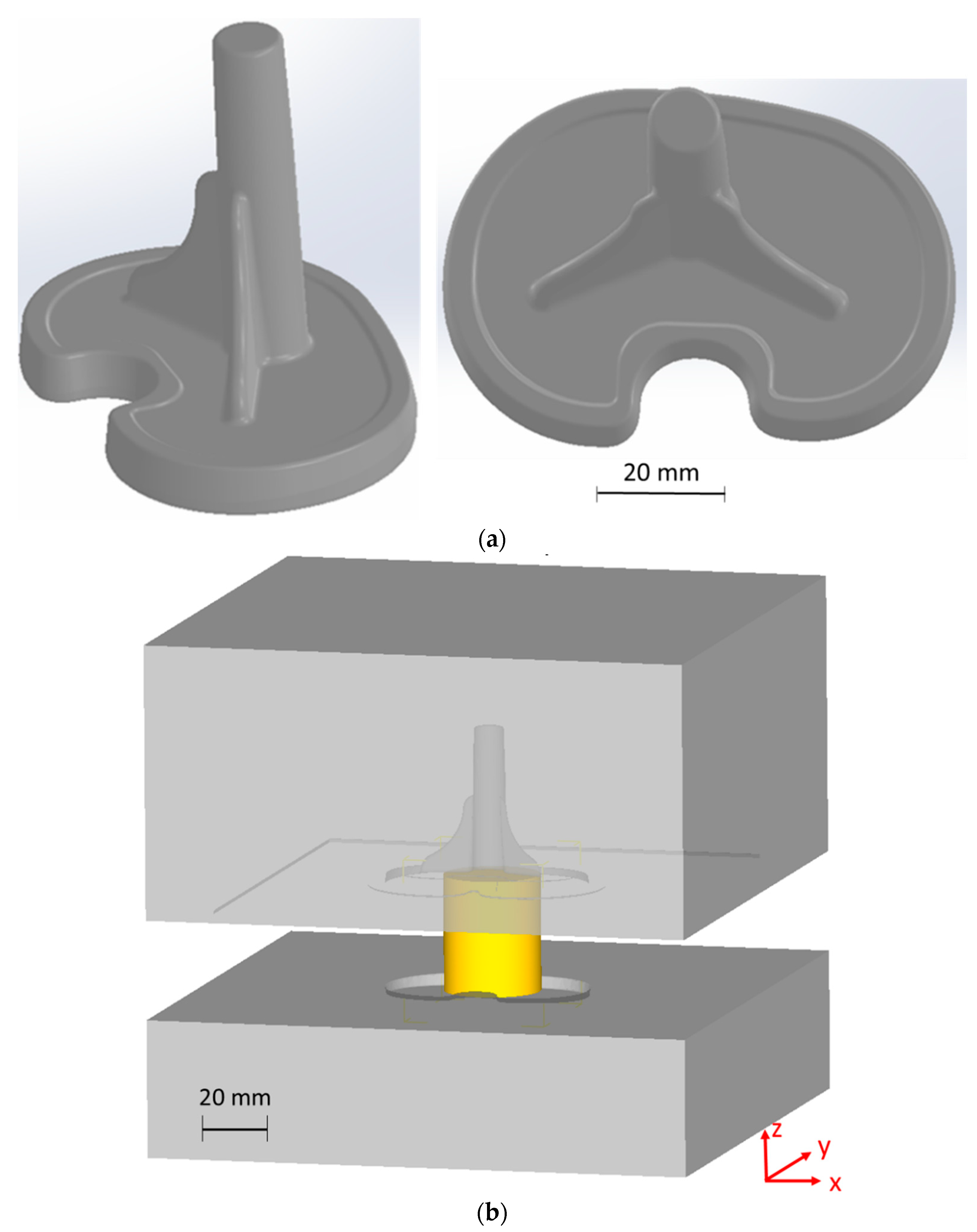
A 3D fully coupled thermal–mechanical forging process modelling framework was developed, using commercial FE forming and forging code, Deform (v11.3) [
24]. The model considered a 35 mm diameter by 42 mm height cylindrical initial billet and used a commercial forging tooling geometry for the production of a medical implant component (see
Figure 1a,b).
As illustrated in
Figure 1a, the medical implant component consists of a central column, with two supporting “wing” structures and a base. It is formed from the initial cylindrical billet as described previously. Convective heat transfer between billet and a stationary air atmosphere was set to 20 W·m
−2·K
−1 [
25], and emissivity was 0.6. Heat transfer between tooling and billet was 5000 W·m
−2·K
−1 [
26]. A friction coefficient of 0.25 was employed at the billet–steel tooling interface [
24]. The surrounding atmosphere was set at 20 °C, and the billet had a starting temperature of 970 °C, in line with suggested forging temperature from the literature [
14]. The lower tooling was set to move toward the fixed upper tooling at a forging speed of 2 mm/s.
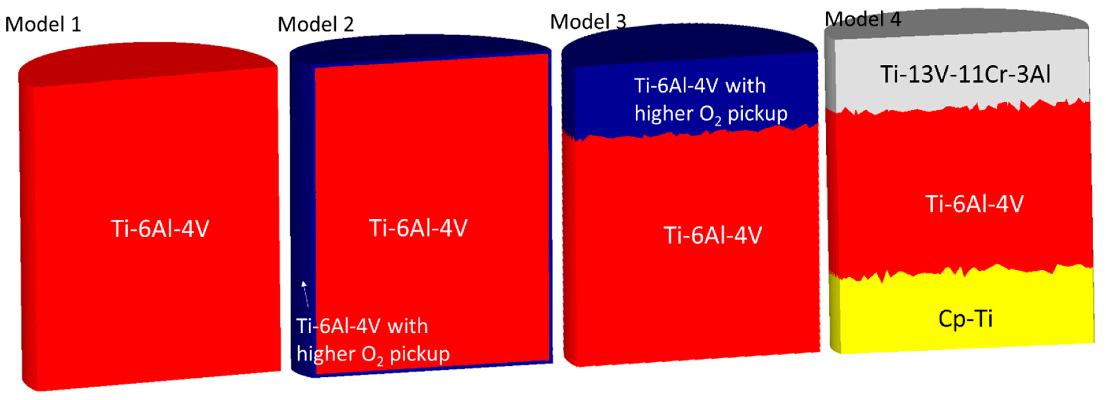
A series of models were prepared and simulated, each with differing partitioning of the initial billet, to assign slightly different material properties to different sections.
Figure 2 and
Table 1 illustrate the starting partitions and material of each billet.
Model 1 was the control case, a simple single partition cylinder, assigned the properties of Ti-6Al-4V ELI with a maximum oxygen content of 0.13 wt %. Materials modelling database JMatPro [
27] was used to predict tabulated flow stress–strain relationships, conductivity, modulus of elasticity, specific heat and Poisson ratio for each material of interest, as a function of temperature. Model 2 considered a partitioned billet with a 500 microns-thick outer shell layer, containing a tabulated material model to represent Ti-6Al-4V with much greater oxygen pick up (½ wt %), and a core of the same basic Ti-6Al-4V ELI as used prior. Model 3 used the same material combinations as Model 2, except in dual bulk layer formation in the initial billet. Whilst Model 4 used a tri-layer bulk partitioning of the initial billet, with the central layer using the standard Ti-6Al-4V JMatPro tabulated model, whilst the other layers used Deform library material files for two different Ti alloys with considerably different conductivity, specific heat and flow stresses, Ti-13V-11Cr-3Al, and CP-Ti.
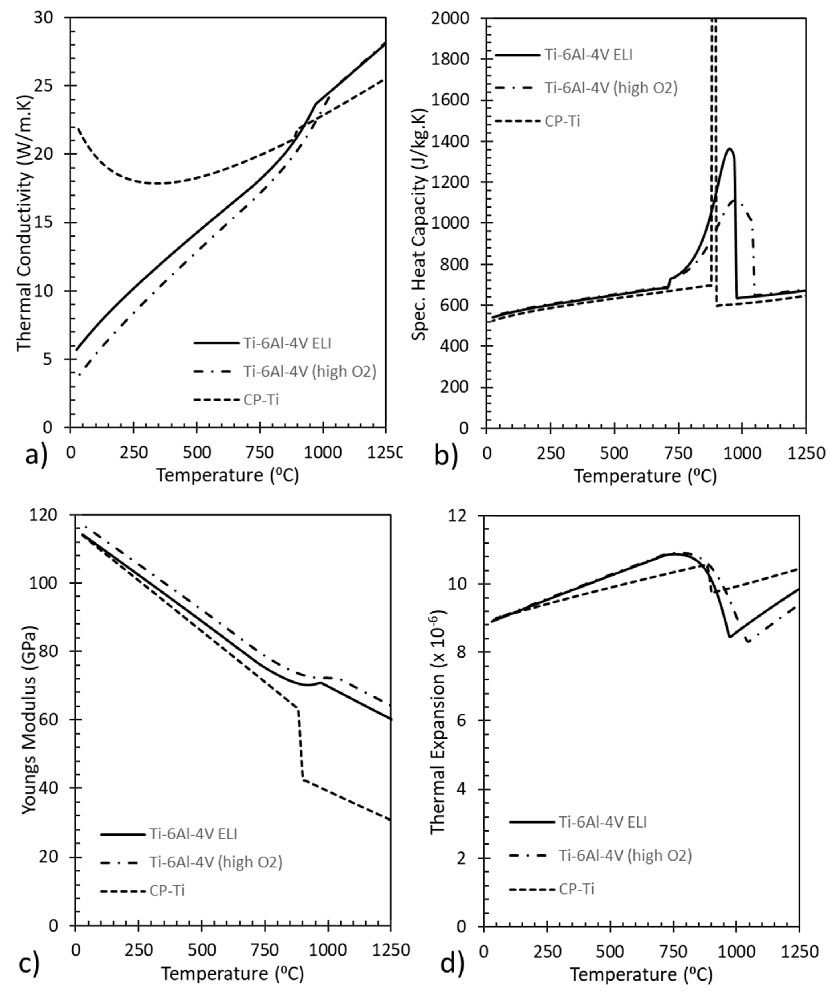
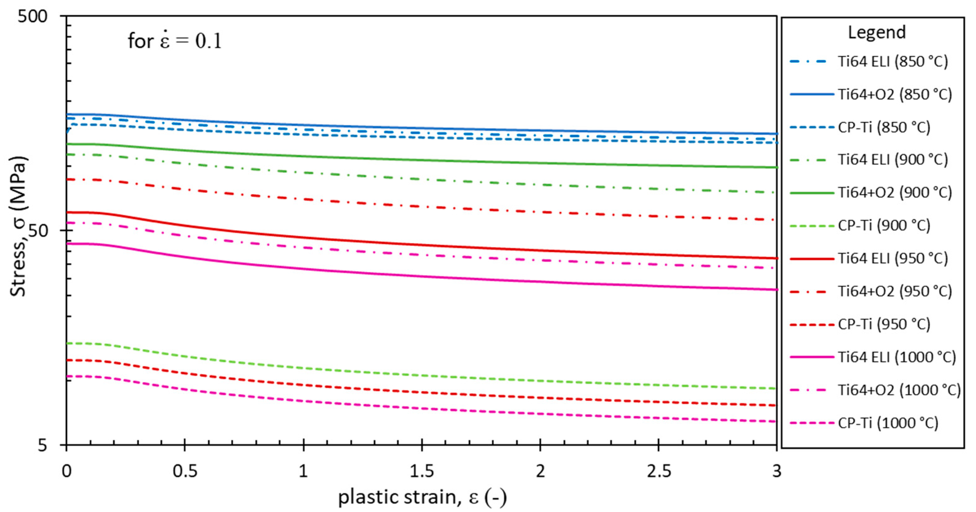
Figure 3 presents the thermo-physical properties, and
Figure 4 presents the stress–strain relationships used in the FE code for the titanium alloys.
No relative sliding at the partition interfaces was permitted. Whilst this represents a considerable assumption for the bulk interface phases, it is a sensible assumption to make for the core and shell model where an outer shell region differs through greater oxygen pick up at the surface. If relative contact between partitions were to be introduced, either a penalty method or a Lagrange multiplier method would be used [
15,
16].
Modelling parameters describe the way the FE software allows the complex thermal and mechanical calculations to be computed, by discretising the time (with a small time-step) and discretising the Cartesian spatial geometry (by breaking the domain in to discrete 3D elements of a mesh). For the process models considered in this work, a time step of 0.05 s was used, whilst the mesh contained 150,000–240,000 elements (depending upon the partitioning arrangement) and automatic re-meshing was triggered at a relative element interference of 0.25 mm.
3. Results
3.1. Thermal
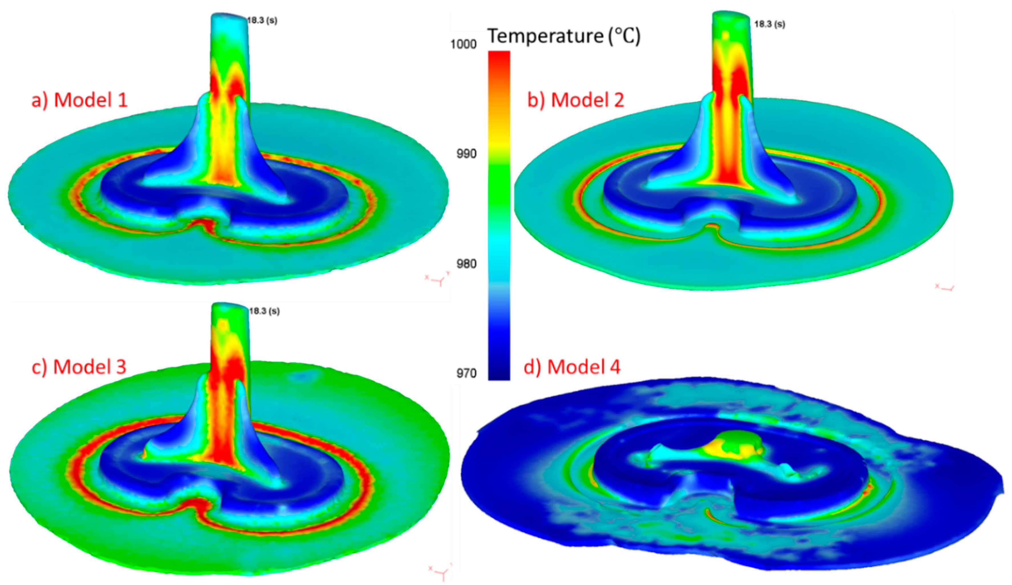
The 3D forging modelling framework was computed in a fully coupled thermal–mechanical environment, with temperature and all mechanical outputs (including stress, strain) computed by the FE software, at each time-step and each element. The thermal predictions within the workpiece after a fixed time period of applied force are presented in
Figure 5. Note that the finished forged component is only the section of the forging that matches the component in
Figure 1a, the remainder is sacrificial flash material for removal, extruded out between the forging tooling, usually as a thin sheet.
As can be observed within the predicted thermal profiles at a fixed time-frame, Models 1 to 3 have only very minor variations within their thermal field. The extruded flash material is predicted to be marginally hotter in Model 3 (with a much larger quantity of the Ti-6Al-4V with greater O2 content), and thus with marginally higher flow stress values at the elevated temperatures of the forging, although the ~1% temperature difference is smaller than the likely error associated with FE modelling, thus negligible. However, peak temperatures in Models 1 to 3 are predicted to be highest at the same locations, namely a ring of extruded flash material which is impinged by a radius within the die, and at the intersection points of the central column with supporting wings. Peak temperatures for these three models are within approximately 1000–1010 °C.
However, for Model 4, the model has predicted a drastically different forging response, which has clearly produced a highly unsuccessful forging. This is caused by the presence of a substantial layer of CP-Ti within the partitioned initial billet, which has a substantially different flow stress characteristic to the considerably more industrially used Ti-6Al-4V, when consulting the literature [
28,
29,
30], as well as interrogation of the values inputted in the material databases for FE modelling, has shown that flow stress–strain curves for CP-Ti to be roughly 10% to 35% lower than that of Ti-6Al-4V, comparing data for alike temperature and strain rate. The softer CP-Ti has deformed so much that the material has moved outside of the tooling guides to form the component, and thus in to the un-recoverable flash material, very shortly after the load was applied. Temperatures are, therefore, lower as the workpiece is not experiencing the same shear-induced heating as for other cases.
3.2. Mechanical Partitions
One benefit of FE modelling is that it is possible to perform a simulated test case of an experiment that would be difficult to set up in reality; as is the case with Model 4, where it would be difficult to experimentally observe the forging response. However, using this combination of CP-Ti and Ti-6Al-4V in a partitioned billet, the softer CP-Ti is deforms easily, therefore, providing no mechanical constraint to drive the Ti-6Al-4V part of the billet into the recessed tooling, and simply forming a larger volume of flash material than is predicted for the other conditions.
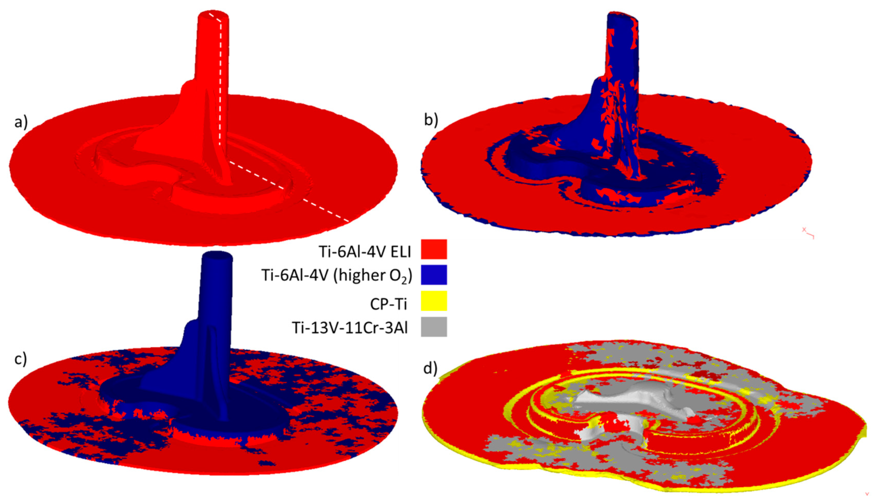
However, it is the location of the partitioned regions of the billet, once the component reaches final forging shape, which will determine whether a forging process such as this has capability to target specific locations within the final component for differing materials properties. The final forging component, with partition regions displayed, are presented to show the component from an isometric view of the surface (
Figure 6) and at a cross-sectional slice through the component (
Figure 7) for all models. Recall that Model 1 is the control model with a single material partition, thus the resulting isometric view and cross-sectional view simply illustrate the single partition and material.
The partitioning of the workpiece after forging in Model 2 (see
Figure 6b) illustrates predicted regions whereby the “core” partition breaks through the outer partition to form a fresh surface as a result of the deformation. This would be an unsatisfactory outcome if the “shell” is required for biocompatibility reasons, hence this may suggest that a thicker outer shell region than the 500 microns used here is required. Further interrogation of the cross-section (
Figure 7b) illustrates the presence of the thin outer shell partition which has thickened in places, but thinned in others. One could use this information as a methodology to target specific locations for specific properties. It is unsurprising that the thin surface partitioning is struggling to remain at the surface of the final forged component at locations with edges and corner features with fillets and radii, where forging strains are likely to be highest.
The partition regions at the surface for Model 3 (see
Figure 6c) are more clearly defined than for Model 2 in the central column, with the interface remaining predominantly a single line, albeit it with some mesh dependence indicated by the triangular protruding boundary. The model predicts that the upper-layer material has formed the entire surface section of the component, barring the bottom half of the base, strongly suggesting that a bulk layered initial billet could nicely produce a uniform surface of the final forged component with targeted properties, based upon this partition’s material composition. It is interesting that the finished component geometry, without the sacrificial flash, maintains a very structured partitioning overall, a result that does strongly imply that different sections of the final forging component shape can be targeted for specific materials with required properties.
However, the flash material, where the thickness is down to less than 2 mm, sees the two partitions mixed in a patchwork-quilt-type pattern. This is likely a realistic prediction, given the very narrow section that the material is being extruded through once it exits the actual desired component geometry, and into the sacrificial flash. Given that this flash is simply to be trimmed away, the fact that the partitions have become very mixed would not be an issue. The extruded flash material displays this very unstructured mix of partitions across all models (except the single partition Model 1), although the effect is most prominent in the two models with bulk layers of differing partitions, namely Models 3 and 4.
Model 4 (see
Figure 6d) predicts a catastrophic forging attempt, based upon the material combination selected. The remnant of the forging is predicted to contain almost entirely Ti-13V-11Cr-3Al in the small portion of the central column that has been successfully formed, and a predominantly Ti-6Al-4V ELI partition in the base of the component. Within the extruded flash there is also largely Ti-6Al-4V ELI, although significant portions of the Ti-13V-11Cr-3Al are present as a patchwork effect. The CP-Ti partition is also present, at the very edge of the flash, where it has been forced out. Model 4 (
Figure 6d and
Figure 7d) also predicts that a region of the CP-Ti partition material becomes trapped at the radii corner regions within the base of the final component. This is because it is the easiest material to deform, and as it was the base layer in the trio of material it has forged into these corner regions early in the process. The frictional condition applied between tooling and billet must then keep the CP-Ti in this location, rather than the following material forcing it to be pushed out.
Note, that the predicted location of partition boundaries does still display some sensitivity to the mesh density. As the partition boundary must not cross through elements, so at times, the triangular 2D elements can be seen protruding or yielding a non-smooth partition. The volumetric proportions of respective partitions can additionally become corrupted at re-meshing stages during the FE modelling process. In order to restrict this as much as possible, the model was forced to maintain volume through both FE calculation and re-meshing steps using the relevant command. Despite this, the predicted bulk separations of the material partitions do suggest that within this framework for the FE modelling of a forging operation, a capability to determine final component partition distributions which may yield enhanced properties based upon differing material composition, including trace element composition such as differing oxygen content, or more substantial alloying element changes, is feasible.
4. Discussion
Industrially, this potentially offers exciting manufacturing developments whereby component forging can be performed after finite element modelling with partitioned billets, to determine final component partition distributions which may allow for enhancements of the component performance in service. Whilst the medical industry is a good example that this methodology could benefit, with specifically biocompatibility in mind, there is no reason why automotive or aerospace components that can currently be forged would not also benefit from this partition distribution modelling approach, and as such, potentially allow for enhanced component properties at critical locations.
In terms of fabrication of an initial billet with “partitions” such as those presented here, further experimental trials would be required. The type of billet partitioning, such as the core and outer shell structure of Model 2, is readily feasible with a short heat treatment—whereby the atmospheric heat only has time to conduct to a certain depth from the surface to give a microstructural variation in the partitions, or with a mass transfer operation such as carburising, nitriding or carbonitriding, to give a compositional variation in partitions. These techniques would, therefore, determine a succession of compositions from the surface to the unaffected core region [
31], which may be represented with a series of discrete partition layers. Whilst these surface heat treatment and mass transfer techniques could equally be adopted post forging to generate surface modifications, they would not allow for any internal partitioning.
Fabrication of a bulk layered billet, which can give subsequent useful internal partitioning after forging, is a little more complex. Experimentally, techniques such as vapour deposition [
32] can generate thin-layered structures, although their rate of deposition may make then unsuitable for bulk-layer structures. A powder interlayer bonding method for titanium alloys [
33] may be able to join two differing alloy layers, although this method would be using powder metallurgy, which would raise the same health and safety issues concerning powder metals in medical implants as for additive manufacturing. A button melting/casting approach may potentially be able to cast and cool each layer of an initial billet on top of one another sequentially, although the wettability of the different alloys would determine the successful bonding between layers, to match the perfect partitioning of the FE model.
However, the optimal use of partitions within the initial billet for forging may be using a combination of the two partition approaches considered in this work, namely a combination of bulk-layered partitions, with an outer shell/coating partition as well. This may offer the best final partition distribution to tailor specific properties. Additionally, varying the forging processing parameters, and the impact this may have upon final forged component partitions has not been explored so far. For this methodology to provide a feasible manufacturing route for the production of components with partition distributions, and as such, targeted locations for enhanced properties, the fabrication of these layered billets would need considerable further experimental research.


