Review

A Systematic Survey of FDM Process Parameter Optimization and Their Influence on Part Characteristics

Department of Industrial and Manufacturing Engineering, North Dakota State University, Fargo, ND 58102, USA
*
Author to whom correspondence should be addressed.
J. Manuf. Mater. Process. 2019, 3(3), 64; https://doi.org/10.3390/jmmp3030064
Submission received: 27 June 2019 / Revised: 23 July 2019 / Accepted: 25 July 2019 / Published: 29 July 2019

Abstract

:
Fused deposition modeling (FDM) is an additive manufacturing (AM) process that is often used to fabricate geometrically complex shaped prototypes and parts. It is gaining popularity as it reduces cycle time for product development without the need for expensive tools. However, the commercialization of FDM technology in various industrial applications is currently limited due to several shortcomings, such as insufficient mechanical properties, poor surface quality, and low dimensional accuracy. The qualities of FDM-produced products are affected by various process parameters, for example, layer thickness, build orientation, raster width, or print speed. The setting of process parameters and their range depends on the section of FDM machines. Filament materials, nozzle dimensions, and the type of machine determine the range of various parameters. The optimum setting of parameters is deemed to improve the qualities of three-dimensional (3D) printed parts and may reduce post-production work. This paper intensively reviews state-of-the-art literature on the influence of parameters on part qualities and the existing work on process parameter optimization. Additionally, the shortcomings of existing works are identified, challenges and opportunities to work in this field are evaluated, and directions for future research in this field are suggested.

1. Introduction

Currently, fused deposition modeling (FDM) is not only used to produce visual aids, conceptual models, and prototypes, but it is also used to produce functional parts such as drilling grids in the aerospace industry [1] and edentulous mandible trays [2]. It reduces assembly cost as it is capable of manufacturing complex geometry and flexible function parts from a stereolithography (STL) file by depositing two-dimensional (2D) layers on a build platform. As of the time of writing, researchers are still working on developing new materials, as well as improving existing materials used in FDM parts in different fields such as aerospace, biomedical, and many other fields. However, the application of the FDM process in manufacturing functional parts is limited due to different drawbacks such as irregular surface, poor mechanical properties, and low accuracy. Although low accuracy is a relative term, as some applications do not require high accuracy (prototypes or display parts), in order for FDM to be more acceptable in the industry and for it to be a good candidate to mass-produce printed parts, accuracy is a basic requirement that is sought for. To produce good functional parts and increase the market share of FDM parts, it is necessary to produce parts with stable qualities to meet specific requirements. The FDM process has several parameters that have a significant impact on built parts. All these parameters affect the bonding between and within the deposited layers. A part with desired qualities can be produced by selecting an optimum combination of process parameters. An important role is also played by the use of the best thermoplastic polymer for the proposed use of the part.
A huge number of researchers analyzed various controllable parameters to achieve desirable properties of parts [3,4,5,6,7], and many also worked on optimizing process parameters [8,9]. Many of the researches optimized process parameters in order to improve a single part’s quality. Rayegani and Onwubolu worked on optimizing tensile strength with a differential evolution (DE) approach [10]. Some researchers also considered more than one part’s quality, but they were analyzed separately [11,12,13]. Additionally, a more advanced approach is to consider two or more parts’ qualities and optimize them simultaneously to obtain a set of optimum combination(s) of parameters. Akande [14], Gurrala et al. [15] and Rao et al. [16] worked on multi-objective optimization. In addition to this review paper, interested readers are encouraged to review two published review papers on FDM process parameter optimization. The first manuscript is by Mohamed et al. [17], where research works until the year 2014 were analyzed. The second manuscript is by Popescu et al. [18]; they reviewed research that considered only mechanical properties as the part characteristics. To complement the two reviewed papers, this paper aims to fill the gaps by systematically representing current and future research trends carried out by researchers on FDM process parameter optimization and their influence. Based on the authors’ knowledge, at the time of writing, the optimization information for FDM process parameters was not concisely reviewed. This paper also serves as an aid for current and future researchers, practitioners, and the general public to set up experiments for the FDM process and to do research on improving or optimizing the characteristics of FDM parts.
The rest of this paper is organized as follows: Section 2 describes process parameters, equipment, and materials. Section 3 reviews the existing papers on FDM part characteristics. In Section 4, the current works on numerical process parameter optimization for the FDM process are discussed. Section 5 defines challenges, opportunities, and future research areas in the improvement of FDM part characteristics. Section 6 provides conclusions.

2. Fused Deposition Modeling

In this section, before summarizing the contributions of existing research and the future directions of research in the field, lists of the process parameters considered for analysis, as well as lists of thermoplastics and FDM machines used for the analysis, are discussed first.

2.1. Process Parameters

The FDM process has several process parameters, and they have a significant impact on production efficiency and part characteristics. Some of the most common process parameters are air gap, build orientation, extrusion temperature, infill density, infill pattern, layer thickness, number of shells, print speed, raster orientation, raster width, and heat treatment temperature (post-processing parameter). The main process parameters are described below.
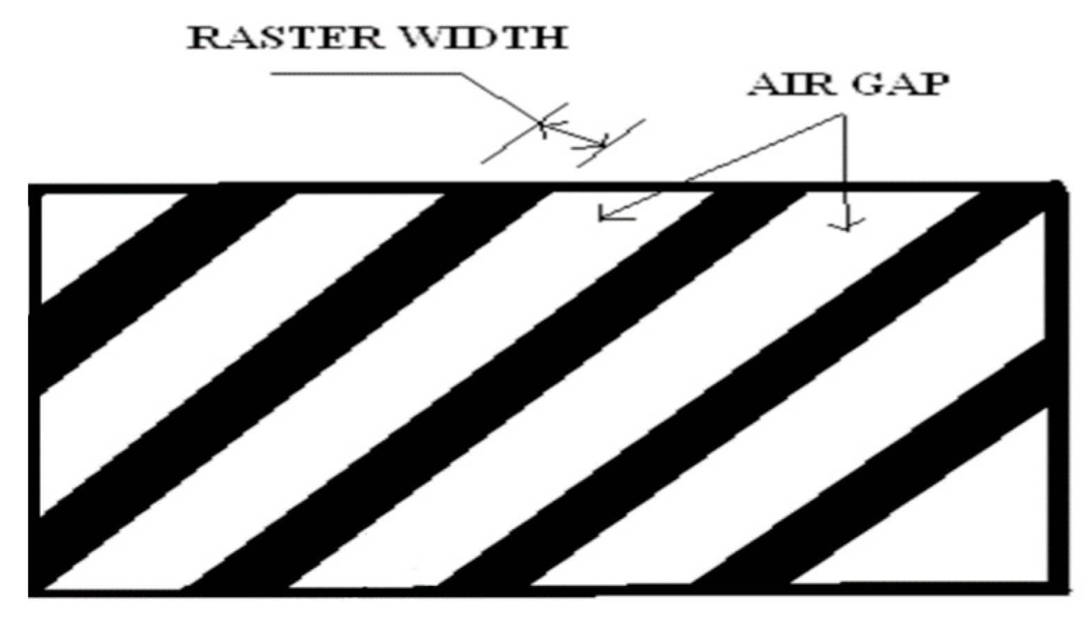
  • Air gap: The gap between two adjacent rasters on a deposited layer. The air gap is called negative when two adjacent layers are overlapped.
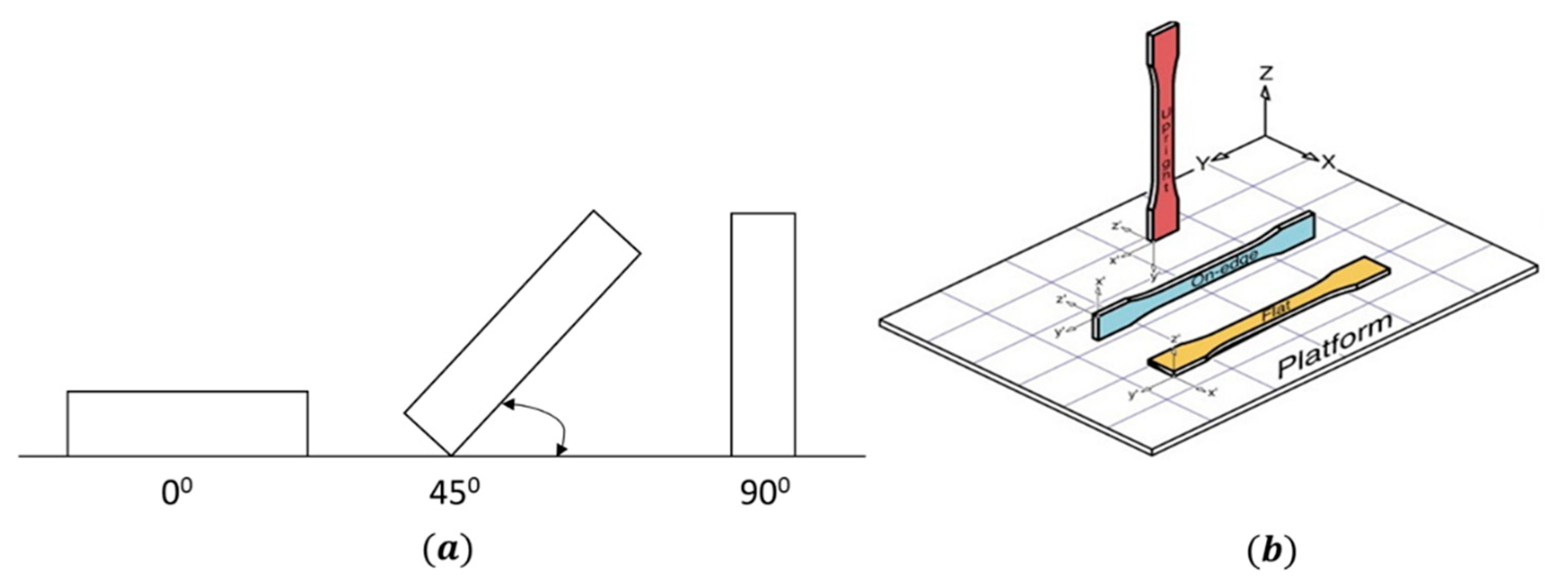
  • Build orientation: Build orientation is defined as the way to orient the part in a build platform with respect to X-, Y-, and Z-axes. In some papers, build orientation represented a quantitative parameter [13,19], but in others, it was considered a categorical parameter [11,20]. Different build orientations are given in Figure 1.
  • Extrusion temperature: The temperature at which the filament of a material is heated during the FDM process. Extrusion temperature depends on various aspects, for example, the type of material or print speed.
  • Infill density: The outer layers of a three-dimensional (3D) printer object are solid. However, the internal structure, commonly known as the infill, is an invisible inner part covered by the outer layer(s), and it has different shapes, sizes, and patterns. Infill density is the percentage of infill volume with filament material. The strength and mass of FDM build parts depend on the infill density.
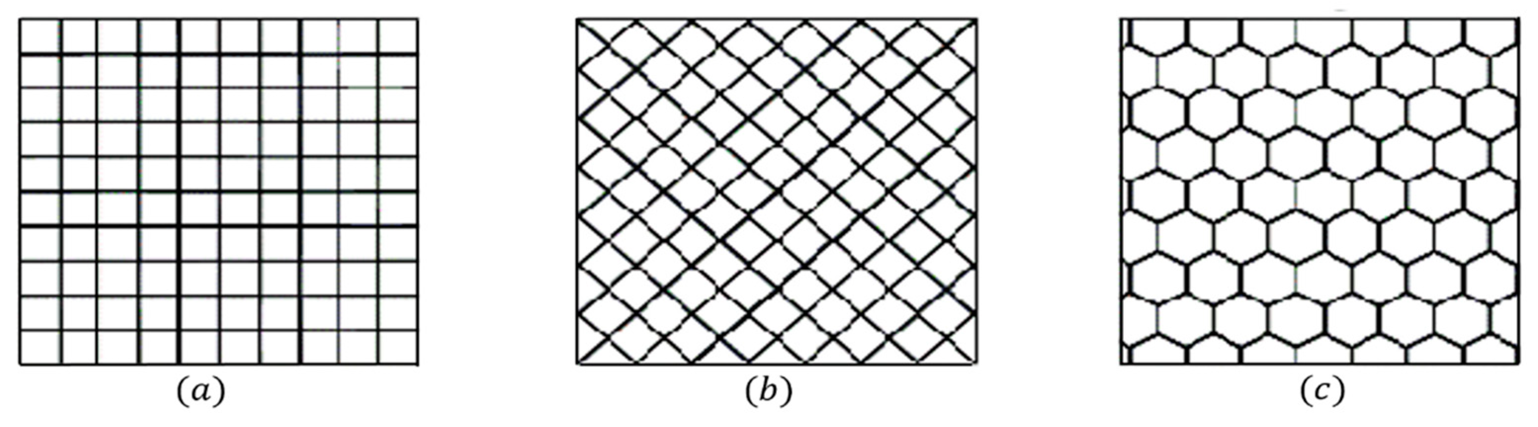
  • Infill pattern: Different infill patterns are used in parts to produce a strong and durable internal structure. Hexagonal, diamond, and linear are commonly used infill patterns (Figure 2).
  • Layer thickness: This is the height of the deposited layers along the Z-axis, which is generally the vertical axis of an FDM machine. Generally, it is less than the diameter of the extruder nozzle and depends on the diameter of the nozzle.
  • Print speed: This is the distance traveled by the extruder along the XY plane per unit time while extruding. Printing time depends on print speed, and the print speed is measured in mm/s.
  • Raster width: Raster width is defined as the width of the deposition beads (Figure 3). It depends on the extrusion nozzle diameter.
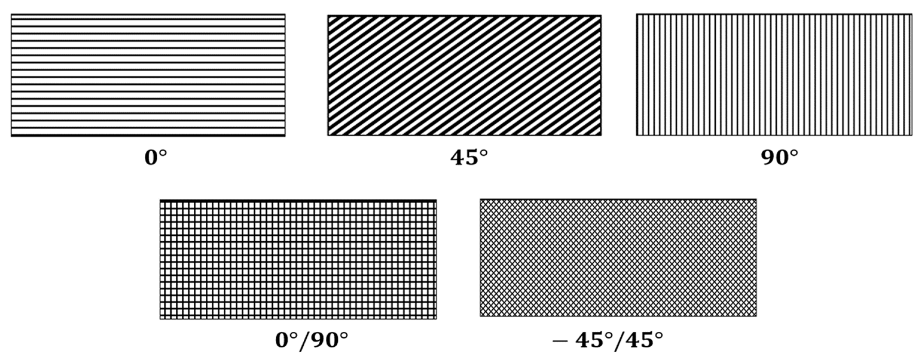
  • Raster orientation: This is the direction of the deposition bead with respect to the X-axis of the build platform of the FDM machine (Figure 4).

2.2. FDM Equipment

For research purposes, different research teams use different FDM machines. Stratasys was one of the first companies to develop the FDM process and FDM machine. The following is a list of commonly used FDM machines: Fortus FDM 400 mc machine (Stratasys, Eden Prairie, MN, USA) [10,21,22], Fortus 360 mc machine (Stratasys, Eden Prairie, MN, USA) [23], FDM 200 mc machine (Stratasys, Eden Prairie, MN, USA) [24], FDM 1650 machine (Stratasys, Eden Prairie, MN, USA) [25,26,27,28], FDM Vantage machine (Stratasys, Eden Prairie, MN, USA) [29,30], Ultimaker 2 (Ultimaker, Amsterdam, Netherlands) [23,31,32], MakerBot Replicator 2 (MakerBot, New York, NY, USA) [33,34], MEM-300 machine (Beijing Yinhua Laser Rapid Prototypes Making and Mould Technology Co., Ltd, Beijing, China) [35], Uprint SE 3D printer (Stratasys, Eden Prairie, MN, USA) [5], The FDM 3000 3D printer (Stratasys, Eden Prairie, MN, USA) [36,37], Raise3D N2plus machine (Raise3D, Irvine, CA, USA) [38], Makerbot Replicator 2X (MakerBot, New York, NY, USA) [1,3,20], Julia 3D printer (Fracktal Works, Bangalore, India) [7], FDM Maxum Machine (Stratasys, Eden Prairie, MN, USA) [39], Prodigy Plus (Stratasys, Eden Prairie, MN, USA) [6,40], WitBox desktop 3D printer (BQ, Madrid, Spain) [11], and HP Designjet 3D CQ656A (HP, Palo Alto, CA, USA) [41].
Please note that the list above is in no way exhaustive. There are also other do-it-yourself (DIY) FDM printers that are highly customizable. Each FDM machine has its advantages and disadvantages. Depending on the controllable process parameters that are offered by an FDM machine, and some other parameters that are difficult to control using a specific machine, each user may have a different view of the equipment. Thus, the advantages and disadvantages of each FDM machine are not the focus of this paper and are not discussed further in this paper.

2.3. Filament Materials

In the FDM process, a part is produced by a filament that passes through a nozzle. Different thermoplastics are used as filaments. The commonly used filament materials are described below [42,43,44].
  • Acrylonitrile butadiene styrene (ABS): ABS, a thermoplastic and amorphous polymer, is one of the commonly used materials to make 3D printed parts via the FDM process. ABS is a copolymer made of acrylonitrile, butadiene, and styrene; impact resistance and toughness are two important mechanical properties of ABS. ABS has a melting point of 230° (standard for printing, although amorphous), which is higher than polylactic acid (PLA)’s melting point [45]. While PLA is biodegradable, ABS is not, but it offers a lower risk of jamming a nozzle.
  • Polylactic acid (PLA): PLA is one of the widely used thermoplastics in FDM. The use of PLA is increasing as it is a biodegradable thermoplastic [46]. Also, it needs less energy and temperature to process prototypes and functional parts with good quality. Now, many desktop 3D printers use PLA as a filament as it does not require a heated bed, although it is prone to jamming a printer nozzle during printing. PLA has higher tensile strength, low warp, and low ductility when compared to ABS. For post-processing, PLA built parts required extra care compared to ABS. In Table 1, some important properties of PLA and ABS are summarized. The presented properties will help choose the right filament for the part to be printed.
  • Polycarbonates (PCs): PCs are a group of thermoplastics known for their good strength, durability, and toughness, and some are transparent. They are high-temperature thermoplastics with good heat resistance, good layer for layer bonding, and they provide a good-quality surface.
  • Polyether ether ketone (PEEK): PEEK is a thermoplastic with excellent heat resistance, mechanical properties, and chemical stability. It has higher mechanical properties when compared to PLA and ABS. PEEK, a biomaterial, is considered as a promising bone repair material to make prostheses for the human body.
  • Polyetherimide (PEI): PEI is widely used in the transportation industry for its high strength-to-weight ratio with low smoke evolution and low smoke toxicity. It requires a high extrusion temperature and bed temperature during printing. Its trade name is ULTEM™ 9085. Due to its low density and toxicity properties, it can be used for aircraft cabins.
  • Nylon: Nylon can be chosen as the filament if the requirement is to print more flexible and more durable parts. It has high toughness and impact resistance, but it is highly sensitive to moisture. Nylon can warp about as much as ABS. Like many other FDM filaments, nylon absorbs moisture from the air as it is hygroscopic. Moisture absorption deteriorates filament properties and results in part characteristic degradation.
  • Other materials: In addition to the commonly used materials discussed above, there are some other materials that are not commonly used or analyzed as filament materials, for instance, high-impact polystyrene (HIPS), polyphenylsulfone (PPSF), polyethylene terephthalate glycol modified (PETG), thermoplastic polyurethane (TPU), bio-composite filaments, ceramic filaments, and other composite material filaments. Most of these materials are either still in the development process or are not easily obtained on the market.
Some research efforts were carried out to compare the properties and functionality of multiple materials for the FDM process. Messimer et al. studied 10 materials to determine whether a heated aluminum–polycarbonate composite print bed was suitable for the FDM process or not [48]. In their updated work, they collected 11 materials to be used in modeling dimensional errors in the FDM process for full-density parts based on seven raster angles and three build orientations [49]. The 11 materials were ABS, PLA, high-temperature PLA, wood PLA, carbon-fiber PLA, aluminum PLA, copper PLA HIPS, PETG, polycarbonate, and nylon.

3. Research on Process Parameter Analysis

A considerable number of researches were conducted to analyze the impacts of process parameters on dimensional accuracy, surface roughness, build time, and mechanical properties. For this survey paper, different keywords were used to search for articles on scientific online databases (e.g., Google Scholar, Elsevier, Springer, etc.). These keywords were FDM, fused deposition modeling, process parameters, FDM optimization, and part characteristics of FDM build parts. Relevant published articles (journals and conference proceedings) from the year 2005 to 2019 are included in this paper, but some important papers from the year 2000 are also included. All the articles reviewed were published in English language only. During the initial search, more than 250 related articles were collected. After an initial screening by reading titles and abstracts, close to 100 papers were used as the main material for this survey paper. In addition to the published articles, manufacturers’ recommendations in the form of manuals or webpages were also used as references for filament properties or suggested printing conditions. For an initial summary of the conducted survey, a fishbone diagram is provided in Figure 5 as a visual representation to illustrate the impacts of different process parameters on various part characteristics. The fishbone diagram was developed based on the outcome of different existing studies. Please note that some process parameters overlap with part characteristics, as one process parameter can affect multiple part characteristics.
In many papers, different statistical tools such as full factorial design [10,24], fractional factorial design [22,25], and face-centered central composite design (FCCCD) [13,50] were used to gain maximum information from a smaller number of experiments. As another approach, optimum levels of parameters for analyzing part characteristics were determined based on experimental results. In some papers, such as Mohamed et al. [51] and Chacón et al. [11], various mathematical models were developed to show a relationship between process parameters and part quality. Peng et al. [35] and Rayegani et al. [10] worked on optimizing mathematical models of part characteristics to determine optimal levels of process parameters. There were also approaches that looked into characteristics of more than one part that were optimized simultaneously. For this, various heuristic optimization algorithms, for example, quantum-behaved particle swarm optimization (QPSO) [8], non-dominated sorting genetic algorithm II (NSGA-II) [15], differential evolution (DE) [10], and genetic algorithm (GA) [52], were used. In the following subsections, a systematic summary of research analyzing each FDM printed part’s quality characteristic is given.

3.1. Dimensional Accuracy

Dimensional accuracy is an important property for functional parts. Adjusting FDM process parameters has a significant impact on dimensional accuracy. Many researchers worked extensively to determine how process parameters can influence the dimensional accuracy of the printed parts.
Wang et al. [53] studied the influence of six process parameters on dimensional accuracy. The examined factors were layer thickness, deposition style, support style, deposition orientation in the Z-direction, deposition orientation in the X-direction, and build location. The authors used the Taguchi orthogonal array (L18) for experimental design, and ABS parts were produced by the Dimension BST rapid prototyping machine according to the experimental design. Their results were reviewed using analysis of variance (ANOVA), which indicated that deposition orientation in the Z-direction was the most significant parameter for dimensional accuracy. Sood et al. [54] analyzed the impacts of five process parameters (layer thickness, build orientation, raster orientation, raster width, and air gap) and their interactions on dimensional deviations along the length, width, and thickness. Their results showed that layer thickness was the most important factor for width and thickness deviations. However, build orientation was most influential for change in length. The authors also observed some shrinkages which occurred in the length and width directions. However, the thickness of the printed part was found to be higher than the computer-aided design (CAD)-defined thickness along the Z-direction. They found that the optimum setting of parameters was different for dimensional deviations and for different dimensions of a part. For this, they used the gray relational grade to convert three target part characteristics into one. We discuss this method in the optimization section of this paper.
Similar to the abovementioned two papers, Nancharaiah et al. [6] used Taguchi’s design of experiments to examine the impact of layer thickness, raster width, raster orientation, and air gap on dimensional accuracy. ANOVA was used to determine significant parameters and their interactions for dimensional accuracy. The ABS parts were produced using a Prodigy plus FDM machine for different combinations of the analyzed parameters. According to their experimental design, it was shown by ANOVA that raster width and interaction between raster width and raster orientation were two significant terms for dimensional accuracy. Other than that, their results indicated that there was a positive correlation between dimensional accuracy and layer thickness. According to their suggestion based on signal-to-noise (S/N) ratio, a smaller layer thickness is preferred for a higher dimensional accuracy.
By using the same machine, Bakar et al. [40] produced a complex shaped part (with slots, cubes, cylinders, and rings) by varying layer thickness, shell width, and internal raster width. The conclusion of their results was that the dimensional accuracy of an FDM part also depends on its shape, and a cylindrical shape has high dimensional deviation. Peng et al. [35] used the MEM-300 machine to produce ABS parts based on uniform experimental design. From their case study, the controllable parameters were line width compensation, extrusion velocity, filling velocity, and layer thickness. They also concluded from the experimental results that low layer thickness was preferable for improving dimensional accuracy. In addition, they also determined the optimum combinations of these four process parameters using response surface method (RSM), fuzzy inference system (FIS), artificial neural network (ANN), and genetic algorithm (GA) for three response variables including dimensional accuracy. All of these techniques are discussed in the upcoming sections.
Akande [14] analyzed the effect of three process parameters (layer thickness, print speed, and infill density) on dimensional accuracy. The results showed that high dimensional errors took place along the thickness (Z-direction) of a PLA part. The author recommended high layer thickness (0.5 mm), low print speed (16 mm/s), and low infill density (20%) for printing parts with high dimensional accuracy. The influence of layer thickness, raster orientation, and build orientation on dimensional accuracy was investigated by Nidagundi et al. [7], and the ABS parts were manufactured by a Julia 3D printer [7]. A Taguchi orthogonal array (L9) and S/N ratio were applied for experimental design and the determination of optimum levels of parameters, respectively. Low layer thickness, 0° raster orientation, and build orientation were found to be optimum for dimensional deviation reduction, and the most significant parameter was indicated as layer thickness.
Mohamed et al. [55] considered six process parameters, and all parameters excluding layer thickness had six levels. In their paper, I-optimal design was used for experimental set-up because the number of levels for each parameter was more than three. They also determined a quadratic equation that represented the relationship between process parameters and dimensional accuracy. Their observational results showed that low layer thickness and number of shells were optimal to decrease the dimensional deviation along the length, width, and thickness. Additionally, the other four parameters (raster orientation, raster width, air gap, and build orientation) had a different optimum combination for dimensional accuracy in different directions. Thus, the desirability function approach was used to determine the optimum combination of all parameters for three-dimensional deviations.
In 2017, Qattawi et al. [20] experimentally examined the impact of two categorical parameters (build orientation and infill pattern) and four numerical parameters (layer thickness, infill density, print speed, and extrusion temperature) on dimensional accuracy. They used PLA as the filament and Makerbot Replicator 2X as the FDM machine. They concluded that layer thickness, extrusion temperature, and build orientation were the three significant parameters among the six parameters for dimensional accuracy. In addition, a low level for both layer thickness and extrusion temperature was preferable to a high level for dimensional accuracy. Tontowi et al. [56] observed the dimensional change of PLA printed parts by a Wanhao Duplicator 5S Mini FDM machine (WANHAO, Jinhua, China) with three process parameters, namely, layer thickness, raster orientation, and extrusion temperature. Unlike other research, their experimental results concluded that raster orientation was more significant than layer thickness for dimensional accuracy. In their paper, the outcomes of the Taguchi orthogonal array and response surface method were compared, and they concluded that the response surface method gave a better prediction. On the other hand, Wu [38] showed that low layer thickness was important for high dimensional accuracy. This conclusion is more aligned with the majority of research in this area. Beniak et al. [57] analyzed the importance of layer thickness and extrusion temperature for dimensional accuracy. Among layer thickness and extrusion temperature, extrusion temperature was significant for dimensional accuracy and, again, a low level for extrusion temperature was preferable.
Short discussion and summary: According to the presented reviewed literature, the layer thickness is one of the most analyzed and influential factors for dimension accuracy. Most of the researchers concluded that high dimensional accuracy is obtained by setting a low layer thickness extrusion temperature and number of shells. In our perspective, further analysis is needed for extrusion temperature and the number of shells for validation of the conclusion. It is observed that shrinkage occurs along X- and Y-directions of build platforms and expansion is experienced along the Z-direction of the build platform. From this, we can conclude that build orientation is also an important parameter of dimensional accuracy. The effects of many process parameters including extrusion temperature, number of shells, infill pattern, and raster width on dimensional accuracy are still unknown. It is important to know the influence of those parameters to produce a part with high dimensional accuracy. Most of the existing research considered only two or three levels of parameters. There is a need to analyze more than three levels of parameters to make a more accurate decision, and to study the impact of the least known parameters on dimensional accuracy (such as extrusion temperature, infill pattern, or nozzle diameter).

3.2. Surface Roughness

Surface roughness is a widely used index of product quality. In most cases, surface roughness is often used as a technical requirement for mechanical products. Surface roughness increases the aesthetic view and is important to ensure proper function of very precise parts, for instance, sealing shafts and friction plates in the automobile sector. One of the limitations of the FDM process is poor surface quality due to the staircase effect, STL file resolution, and process parameters. The impacts of the staircase effect and STL file resolution depend on the shape complexity of a part (e.g., a curved surface is harder to obtain than a flat surface). The influence of process parameters on surface roughness not only depends on the shape of a part, but also on the setting of process parameters. The surface quality of an FDM built part can be improved by selecting an optimum combination of process parameters. Higher surface quality typically reduces post-processing cost.
Vasudevarao et al. [28] investigated the influence of build orientation, layer thickness, raster width, air gap, and model temperature on the surface roughness. For this, parts produced by the Stratasys FDM 1650 machine for different combinations of process parameters were analyzed by half factorial design. The results of the experiment showed that low layer thickness and high build orientation reduced surface roughness, but other parameters were not significant for surface quality. According to Anitha et al. [58], among layer thickness, raster width, and print speed, the layer thickness was found to be the most important parameter for surface quality. Raster width and print speed were almost equally significant for surface quality. Thrimurthulu et al. [59] also recommended a low layer thickness for high surface finishing. The impacts of three process parameters, namely, layer thickness, extrusion temperature, and visible surface, were investigated by Horvath et al. [60] to know the importance of those parameters for surface roughness, and a full factorial experimental design was used for the experiments. The results of the experimental study were aligned with the results found by Vasudevarao et al. [28], where layer thickness was the most significant parameter, and the extrusion temperature was insignificant. They also recommended a fine raster width for reducing surface roughness.
Wang et al. [53] studied the impact of six process parameters on surface roughness along with dimensional accuracy. Among the analyzed six parameters, the layer thickness was the most significant parameter for surface roughness, but build orientation in the Z-direction was the most significant parameter for dimensional accuracy. Galantucci et al. [61] experimentally investigated the impact of layer thickness, raster width, and tip size (nozzle diameter) on the roughness of the top and side surfaces. Their results indicated that layer thickness and raster width were significant for the side and top surface roughness of ABS printed parts. Other than dimensional accuracy, Nancharaiah et al. [6] also investigated the impact of four parameters (layer thickness, raster width, raster orientation, and air gap) on surface roughness. Their results showed that layer thickness and raster width had an influence on surface roughness and also recommended that the negative air gap degraded surface quality.
Bakar et al. [40] analyzed layer thickness, shell width, and internal raster to determine the significance of those parameters for improving surface finishing. The surface quality of a top surface is better than the side surface. The shape of a part is important for reducing surface roughness, and a complex curvy surface reduces surface finishing. According to their paper, a wider raster width increases surface finishing as heat and high temperature easily affect the smaller raster. Like other researchers, they also recommended that low layer thickness is preferable for good surface quality. Akande [14] used a 3D Touch FDM machine and PLA as the filament material to produce cuboid-shaped specimens based on full factorial design, and investigated the importance of layer thickness, infill density and print speed for surface roughness. The lower level of each parameter was optimum for maximizing surface finishing.
Along with many other part characteristics, Nidagundi et al. [7] analyzed surface roughness as well. In their research, the analyzed process parameters were build orientation, layer thickness, and raster orientation, and a Taguchi orthogonal array (L9) was applied to reduce the number of experiments. Based on the reduced experimental design, ABS printed parts were produced by a Julia 3D printer and the average Ra value (surface roughness) was used as a measurement for optimum surface roughness. Their results indicated that 0.1 mm (minimum) layer thickness on the top and side surfaces, 0° build orientation, and 0° raster orientation were the settings for achieving optimum surface roughness. Raju et al. [19] also showed that layer thickness and build orientation were two significant parameters for surface quality. Valerga et al. [62] analyzed various PLA filament conditions to know their impact on surface quality, along with the dimensional accuracy and tensile strength of the FDM printed part. They considered extrusion temperature, humidity, and pigmentation color as variables. They drew a conclusion that a lack of pigmentation and a low extrusion temperature were preferable for better surface quality. Unlike most of the previously mentioned research, Pérez et al. [63] used a cylindrical-shaped specimen instead of a cuboid-shaped specimen. In their study, layer thickness, print speed, extrusion temperature, and shell thickness were the analyzed parameters. Their findings showed that low layer thickness was favored for good surface finishing, but extrusion temperature and print speed were insignificant.
Short discussion and summary: High surface finishing can be achieved by selecting a low layer thickness because it helps reduce the staircase effect on the printed parts. Other than layer thickness, low extrusion temperature and print speed are preferable to achieve a higher print precision. A high extrusion temperature increases the fluidity of filament materials and further results in high dimensional deviation and surface roughness. Most results indicated that the surface finish of a top printed surface is better than the side surface for any setting of process parameters. Therefore, printing the shortest side of a part in the Z-direction is recommended for the FDM process to reduce the overall surface roughness. For an inclined part’s orientation, neither horizontal nor vertical orientations increase surface roughness. Thus, if possible, it is best to avoid printing on an inclined orientation.

3.3. Mechanical Properties

The mechanical properties of a part are important. Depending on the application areas, mechanical properties can be used as one of the guidelines to explore new applications or to determine the expected service life of a part. Due to different process parameters (e.g., extrusion temperature and layer thickness), mechanical properties of an FDM built part are not the same as the mechanical properties of the filament. There were a lot of research efforts that investigated the impact of process parameters on mechanical properties [18]. Tensile strength, compressive strength, and flexural strength were the three most widely analyzed mechanical properties of FDM parts. In this section, the current research related to tensile strength, compressive strength, and flexural strength is summarized systematically.

3.3.1. Tensile Strength

Tensile strength is one of the most analyzed mechanical properties. In most of the papers, the parts for the tensile test were produced according to the American Standard for Testing and Materials (ASTM) D638 standard. This standard is used for testing the tensile properties of thermoplastics. The test specimens were dumbbell-shaped. Some of the recent work is summarized below.
Montero et al. [25] investigated five process parameters (air gap, raster width, extrusion temperature, filament color, and raster orientation) and designed their experiment according to fractional factorial design. Their printed specimens were produced from ABS using a Stratasys FDM 1650 machine. The experimental results showed that the air gap and raster orientation were two significant parameters for tensile strength, and a negative air gap and 0° raster orientation were preferable for maximum tensile strength. Es-Said et al. [26] analyzed the tensile properties of ABS parts manufactured by the FDM process by considering raster orientation as the variable. For this, ABS parts were produced for five different raster orientations. Like other research, it was shown that a raster orientation of 0° was best to maximize the tensile strength. Along with surface roughness and dimensional accuracy, Wang et al. [53] also analyzed the impact of the six parameters on tensile strength, and showed that build orientation in the Z-direction was the most significant parameter for the tensile strength property. Layer thickness, build orientation, raster width, raster orientation, and air gap were considered as variables to examine their impact on tensile strength by Panda et al [13]. Their experiment was designed according to FCCCD, and a quadratic equation was formulated for the tensile property. They showed that all parameters (other than raster width), and the combinations of parameters were influential for tensile strength.
Bagsik et al. [64], Domingo-Espin et al. [65], and Letcher et al. [3] tested the tensile strength of Ultem 9085, PC, and ABS parts, respectively, in different build orientations. The first two groups of researchers showed that tensile strength was maximum when build orientation was 0° in the X-direction, but the outcome of the third group’s experimental study was different. In separate research, Hernandez et al. [66] showed that the influence of build orientation was not significant for the tensile strength of ABS P430 built parts. The influence of five process parameters (layer thickness, build orientation, raster orientation, raster width, and air gap) on tensile strength was studied by Sood et al. [12]. Their parts were built by an FDM machine according to FCCCD; a quadric equation for tensile strength was formulated using the response surface method, and ANOVA was used to determine the significance of different terms in the equation. It was shown that all parameters, excluding raster width, and the interactions of different parameters were significant. They also plotted response surface graphs to visualize the change of tensile strength with the interaction between two parameters. Fatimatuzahraa et al. [67] investigated the impact of raster orientation on the mechanical properties, including tensile strength, of ABS parts. Three parts, each having four different raster orientations, were produced, and parts were tested by a destructive tensile testing machine. The results concluded that tensile strength was maximum and almost the same at the cross (0°/90°) and crisscross (45°/−45°) raster orientations.
Croccolo et al. [68] analyzed the impact of the number of shells on the tensile strength, and showed that the property increases with the increase in the number of shells. Rayegani et al. [10] investigated five process parameters (layer thickness, build orientation, raster orientation, raster width, and air gap) to get an optimum combination of the process parameters that maximize the tensile strength of ABS printed parts. For this purpose, the group method of data handling (GMDH) approach was used to develop a mathematical model that related process parameters with tensile strength. In order to maximize tensile strength, a differential evolution (DE) optimization approach was applied to get levels of each parameter. The optimization results showed that tensile strength approached a maximum at the minimum setting of layer thickness, build orientation, raster width, and negative air gap. Raster orientation was found to be comparatively less significant. On the other hand, Panda et al. [69] also used DE to get an optimum combination of process parameters for tensile strength. However, the combination of process parameters (high layer thickness, raster width, and positive air gap) was different from the combination obtained by Rayegani et al. [10].
Durgun et al. [4] analyzed the impact of build orientation and raster orientation on tensile properties. Their experimental investigation results suggested that 0° raster orientation and 0° build orientation were suitable to optimize tensile strength. Build orientation was found to be more significant than raster orientation. Gorski [70] analyzed the importance of build orientation on tensile strength and the brittleness property of FDM built ABS parts. The author showed that tensile strength was maximum at 0° build orientation. However, the FDM built part became brittle when the build orientations exceeded 20° in the X-axis and 25° in the Y-axis. Wu et al. [71] showed that layer thickness and raster orientation were both significant for the tensile properties of PEEK parts. Additionally, the authors also compared PEEK with ABS, and the comparison outcome was that PEEK parts performed better under tensile loading when compared to ABS parts. However, for both materials, the mechanical properties of the FDM parts were worse than injection molded parts.
Other than dimensional accuracy and surface roughness, Nidagundi et al. [7] analyzed the impact of layer thickness, build orientation, and raster orientation on the ultimate tensile strength property. The number of experimental runs was selected by a Taguchi orthogonal array, and a low level of S/N ratio for all three parameters was recommended for tensile strength. Ziemian et al. [72] researched raster orientation as the only variable to determine the significance and the optimum level of the parameter for tensile properties. For this purpose, ABS parts were produced for different raster orientations, and tensile properties (yield strength and ultimate strength) were found to be maximum at 0° raster orientation and minimum at 90° raster orientation. Wittbrodt et al. [73] showed that the filament color of PLA was found to be significant for tensile properties. Torres et al. [74] investigated the influence of extrusion temperature, print speed, raster orientation, infill density, layer thickness, and perimeter (number of shells) on the tensile properties of PLA parts for different build orientations. Their outcome indicated that build orientation was one of the most significant parameters for tensile strength, and other tensile properties were also affected by build orientation.
Torrado et al. [75] investigated the tensile strength of FDM parts for a set of unique variables, part geometry, and raster orientation. In their research, ABS parts were built for different geometries (Type I, IV, and V) of ASTM D638 standard, as well as different raster orientations. Rankouhi et al. [76] analyzed the importance of two process parameters (layer thickness and raster orientation) for the tensile properties of FDM built ABS parts. For experimental analysis, they considered two and three levels of layer thickness and raster orientation, respectively. According to their experimental results and statistical analysis, layer thickness and raster orientation, as well as their interaction, were significant. Additionally, the ultimate tensile strength and elastic modulus were maximum at lower levels of both parameters. The microscopic inspection of the fracture area showed that a smaller air-gap-to-material ratio contributed to tensile properties.
Chacon et al. [11] investigated the importance of layer thickness, print speed, and build orientation for tensile properties. They showed that tensile strength was minimum at an upright build orientation (90°) and was almost the same at two other build orientations (on-edge and flat). Another finding was that the levels of layer thickness and print speed depended on build orientation. Uddin et al. [77] determined the impact of three process parameters on tensile properties. They showed that the mechanical properties of FDM parts, regardless of material, were lower than injection molded parts. The experimental outcomes revealed that the combination of process parameters was the same as the combination obtained by Chacon et al. [11]. Cantrell et al. [23] showed that tensile properties (yield strength and ultimate strength) were minimum at upright built orientation, and maximum at flat and on-edge build orientations for ABS and PC parts, respectively. Also, the authors showed that tensile properties were maximum at (0°/90°) and (−45°/45°) raster orientations for ABS and PC parts, respectively. Raney et al. [5] produced ABS parts using a Uprint SE 3D printer and analyzed the influence of build orientation on tensile strength. Aligned with most researchers, tensile strength was found to be maximum at on-edge build orientation.
Qattawi et al. [20] determined significant parameters for tensile properties from build orientation, infill density, infill patterns, print speed, extrusion temperatures, and layer thickness. Among the six parameters, build orientation, layer thickness, infill density, and extrusion temperature were significant for tensile properties (Young’s modulus, tensile strength, yield strength). Liu et al. [33] analyzed layer thickness, build orientation, raster orientation, raster width, and air gap and determined an optimum combination of process parameters for the tensile properties. The authors designed parts for the tensile test and the experiment according to GB/T 1040.2-2006 (Chinese Standard) and a Taguchi orthogonal array, respectively. From the five parameters, layer thickness (high), build orientation (60°), and raster orientation (−45°/45°) were significant for tensile strength. The optimum levels of significant parameters were different from most of the existing research. Tontowi et al. [56] investigated layer thickness, build orientation, and raster orientation for tensile strength, as well as dimensional accuracy, and showed that build orientation was the most significant parameter. The authors also recommended that RSM was a better approach than a Taguchi orthogonal array.
According to Mahmood et al. [78], the ultimate tensile strength of ABS parts depended on the cross-section area (width × thickness), infill density, and number of shells. The property was proportional to infill density and number of shells; however, it was inversely proportional to the cross-section area. A metamodel for tensile force was developed by Raju et al. [19], and they showed that layer thickness and build orientation were also the two most significant parameters among the four parameters for tensile properties. Aw et al. [79] determined the impacts of infill density and infill pattern (rectilinear and line) on the tensile properties of ABS/ZnO and conductive ABS/ZnO (CABS/ZnO) built parts. Their study revealed that 100% infill density and a line infill pattern maximized tensile strength. Similar to Mahmood et al. [78], Kung et al. [80] showed that the cross-section area and the number of shells were significant for tensile strength. Additionally, Kung et al. [80] showed that tensile strength was maximum at a −45°/45° raster orientation.
Vosynek et al. [81] compared PETG filaments produced by two different suppliers. They considered filament color, infill pattern, build orientation, infill density, and raster orientation as variables, showing that build orientation was the most significant parameter, and the tensile strength was maximum at a flat build orientation. Infill density and raster orientation were also significant for tensile strength. For FDM produced PEEK parts, Deng et al. [82] designed experiments according to a Taguchi orthogonal array, and showed that high print speed, low layer thickness, and high extrusion temperature were preferable for tensile strength. However, one of their contradictory outcomes was that the tensile strength was maximum at 40% infill density instead of at maximum infill density (60%). Rinanto et al. [83] applied the Taguchi orthogonal array for experimental design, and the controllable parameters were infill density, raster orientation, and extrusion temperature for PLA parts. The study revealed that a high extrusion temperature and infill density and a 45° raster orientation were optimum for tensile strength. Fernandes et al. [31] analyzed infill density, extrusion temperature, raster orientation, and layer thickness, and the optimum combination for tensile properties was high infill density and extrusion temperature, low layer thickness, and 0°/90° raster orientation. On tensile strength, the influence of layer thickness, print speed, and infill density was separately analyzed by Taiyong et al. [84]. Tensile strength was maximum at low layer thickness and high infill density; however, unlike other research, it was shown that tensile strength was maximum at low print speed. Rodríguez-Panes et al. [85] compared the tensile properties of FDM built ABS parts and PLA parts by varying layer thickness, infill density, and build orientation. The tensile properties (modulus of elasticity, nominal strain at break, yield stress, and tensile strength) of PLA were better than the case of ABS.
Short discussion and summary: Compared to any other part characteristics, tensile properties, especially tensile strength, are the most analyzed part characteristics in FDM printed parts. From existing research, the build orientation was found to be the most significant parameter, and tensile strength was maximum at 0° (or flat/on-edge) build orientation. At this build orientation, the direction of filament fiber extrusion is parallel to the direction of the applied load. Layer thickness depends on other parameters, for instance, build orientation, and is optimum at 0° build orientation. Low layer thickness is recommended for tensile properties. It is safe to conclude from the current research, as well as general knowledge, that tensile strength is maximum at high infill density and a high number of shells. At high density, interlayer bonds become strong. High extrusion temperature is preferable for tensile strength. This is because, at a high temperature, the fluidity of the filament increases, and interlayer bonds become stronger. The optimum raster orientation for tensile strength is still contradictory, but it may be concluded that a 0°/90° or −45°/45° raster orientation is optimum. Additionally, the color is also a significant factor for tensile strength, and tensile properties are maximum for natural color filaments.

3.3.2. Compressive Strength

For the functional use of FDM printed parts, mechanical properties are also important, along with dimensional accuracy and surface roughness. Compressive strength is one of the most important mechanical properties and, like other part characteristics, it is also affected by process parameters. For the compressive test, almost all papers followed the ASTM 695 standard for compression test of rigid thermoplastics, as there is no standard for testing the mechanical properties of additive manufacturing build parts. In the FDM process, the generally used test specimens for this standard are shaped as follows: (1) right cylinder with 12.7 mm diameter and 25.4 mm height, or (2) rectangular prism with 25.4 mm × 12.7 mm × 12.7 mm dimensions. The speed of the load shell for the testing of compressive properties is in the range of 1.3 ± 0.3 mm/min. In this section, the surveyed literature related to compressive strength is systematically reviewed.
Ang et al. [27] used the FDM process to produce an ABS scaffold structure for tissue engineering and analyzed the impact of different process parameters (air gap, raster width, build orientation, build layer, and build profile). Among those parameters, air gap and raster width were the two significant parameters for compressive strength, and the preferable levels for both parameters were lower and upper levels, respectively. Bagsik et al. [64] analyzed the impact of build orientation on the compressive properties of ULTEM™ 9085 built parts, and only two build directions were considered, 0° and 90°. Their experimental results showed that the compressive property was higher along 90°. Sood et al. [8] investigated the influence of five process parameters on compressive stress, but also developed a quadratic equation that showed the relationship between process parameters and compressive stress. Their outcomes indicated that a complex nonlinear relation existed, and the interaction of process parameters was also important for compressive stress. Unlike the previous research, their results also showed that low build direction, along with high layer thickness, increased compressive stress, but raster width was insignificant.
For a full factorial experiment, extrusion temperature, raster width, filament color, raster orientation, and air gap were considered as variables, and the impact of the variables on compressive strength was analyzed by Ahn et al. [86]. They recommended five build rules for producing a part by FDM based on an experimental study. Unlike most research findings, the experimental results of cylindrical-shaped ABS parts showed raster orientation was significant, but build orientation was insignificant for compressive strength. Lee et al. [36] analyzed only the influence of build orientation on compressive strength and showed that build orientation was significant, and the strength was maximum at 0°. They concluded that parts produced by additive manufacturing had a low compressive strength compared to other processes, but FDM process produced parts had a relatively good compressive strength. Wu et al. [71] showed that layer thickness was significant for compressive strength, but their outcomes indicated that the center level maximized the properties. In order to compare ABS and PEEK materials, they produced parts by both materials and tested the compressive strength and modulus. The outcome was that PEEK had higher mechanical properties, although it demonstrated an inconsistent stress–strain curve when compared to ABS. Compressive properties of ABS parts were analyzed by Baich et al. [87], and the infill pattern was their chosen variable. The summary of their work was that the compressive properties of a part increase as shape complexity increases.
Hernandez et al. [66] analyzed the importance of build orientation for maximizing compressive properties, along with other mechanical properties. For this, three levels of the process parameters were considered, and parts were produced by a uPrint SE Plus 3D printer from ABS P430 filaments. The experimental outcome was that 0° build orientation increased compressive strength, compressive yield strength, and compressive modulus. On the other hand, compressive strength was found to be minimum at 45° build orientation. Unlike other researchers, Zaman et al. [1] produced function parts for the aerospace industry to study how layer thickness, infill pattern, infill density, and number of shells were important for compressive properties. In the paper, the experimental study was designed according to a Taguchi orthogonal array (L8), and specimens were produced from PLA and PETG by a Makerbot Replicator 2X and Open Edge HDE machine, respectively. The outcome of the experiment and statistical analysis (ANOVA and S/N ratio) showed that the compressive strength of PETG built parts was slightly better than PLA built parts. Note that, in their study, different machines were used for different materials.
Short discussion and summary: Research conducted to analyze the impacts of compressive stress is still limited, and different researches used a different combination of process parameters. In most of the reported research, it was necessary to use the same values for constant parameters for valid comparisons. In our view, further investigation is needed to draw a valid conclusion about the influence of a parameter (or combination of different parameters) on compressive strength. However, from the existing research, it can be initially concluded that a high level of layer thickness increases compressive properties. In addition, part orientation is important for comprehensive strength as it changes the anisotropic properties of FDM parts. From experimental results, as well as general knowledge, it is also safe to conclude that high infill density, complex infill shape, and a high number of shells are preferable for improving the compressive properties of the printed parts. To know more about the influence of process parameters, it is important to investigate extrusion temperature, infill pattern raster width, and raster orientation. According to the state-of-art research, there is still limited research that compares the mechanical properties of parts produced from different materials. This is a research gap that needs to be filled in this field.

3.3.3. Flexural Strength

Flexural strength is an important mechanical property like tensile and compressive strength for functional parts. ASTM D790 is an international standard for testing the flexural properties of thermoplastics. A three-point loading system is typically used for flexural strength. The load is applied to the specimen, and the specimen simply acts as a supported beam. In this section, the existing research on determining the impacts of FDM process parameters on flexural properties is summarized extensively.
The impact of layer thickness, build orientation, raster width, raster orientation, and air gap on flexural strength was investigated by Panda et al. [13], along with tensile strength. The outcome of their experimental study and statistical analysis was that all parameters, as well as their combination, were significant for flexural strength. Sood et al. [12] considered the same parameters, and a response surface equation for flexural strength was developed that showed the relationship between process parameters and the obtained strength. Other than that, response surface plots were also used to describe the significance of the interactions of two parameters for flexural strength. A high level of layer thickness and raster width, and a low level of the other parameters were deemed to increased flexural strength. The optimum raster orientation for flexural strength was determined by Fatimatuzahraa et al. [67] with ABS parts produced by a Dimension SST 768 FDM machine with four different of raster orientations. They concluded that flexural strength was maximum at a 45°/−45° raster orientation.
Durgun et al. [4] investigated build orientation and raster orientation to determine the levels of both parameters that maximized the flexural strength of ABS parts. Their finding was that 0° raster orientation and 0 build orientation maximized flexural strength, as well as surface roughness. Lužanin et al. [88] produced PLA parts by a MakerBot Replicator 2 for investigating flexural strength. The analyzed process parameters were layer thickness, build orientation, and infill density. Based on the experimental results and statistical analysis (ANOVA), layer thickness and the interaction between build orientation and infill density were significant for flexural strength. Raut et al. [89] analyzed the impact of built orientation on flexural strength of ABS parts produced by a Stratasys FDM machine. For the build orientation, the outcome of the analysis was the same as the outcome by Durgun et al. [4]. Hernandez et al. [66] considered only one process parameter, which was build orientation, to analyze the impact on the flexural strength. Parts were produced according to ASTM D790 from ABS P430 filament, and the results indicated that flexural properties, like compressive properties, were maximum at 0° build orientation. Liu et al. [33] designed their experiments based on a Taguchi orthogonal array, and PLA parts were designed according to GB/T 9341 (a Chinese testing standard). According to ANOVA analysis at a 5% significance level, they concluded that build orientation, layer thickness, and raster orientation were significant for flexural strength.
Wu et al. [71] compared flexural properties along with tensile and compressive properties for PEEK and ABS. Unlike tensile and compressive properties, the experimental outcome showed that flexural properties were almost similar for both materials. Christiyan et al. [90] analyzed the impact of layer thickness and print speed on flexural strength. Unlike most research findings, the composite parts were built from ABS and hydrous magnesium silicate according to ASTM D790. The experimental investigation showed that flexural strength was maximum at a low layer thickness and print speed. The influence of two quantitative parameters (layer thickness and print speed) and one categorical variable (build orientation; flat, on-edge, and upright) on flexural strength was analyzed by Chacon et al. [11]. For flexural strength, like tensile strength, they developed a quadratic model for each build orientation. The flexural strength was found to be maximum at on-edge build orientation, and optimum layer thickness and print speed depended on build orientation. Raju et al. [19] considered layer thickness, build orientation, the support material, and the model interior as variables, and ABS parts were produced according to a Taguchi orthogonal array (L18). To demonstrate the relationship between the four process parameters and flexural strength, a linear regression model was developed, and, based on the equation, their research summary was that a high layer thickness and a low build orientation increased the flexural strength.
Short discussion and summary: Flexural strength is one of the least analyzed mechanical properties in comparison to compressive and tensile strength. Based on the analysis of the existing research, it can be concluded that the relationship between flexural strength and process parameters is more complex compared to tensile or compressive strength. This is because, during flexural strength testing, a component experiences both tensile and compressive force. Flexural strength is maximum at 0° build orientation. In this build orientation, the orientation of the filament is perpendicular to the direction of the load applied. Further research is required to know the impact of various process parameters, including layer thickness, raster orientation, print speed, and air gap on flexural strength. Based on the current literature review, the impact of some parameters such as infill pattern, extrusion temperature, and infill density on flexural properties was not widely analyzed. As one of the future research directions, it will be valuable for public information if more parameters are analyzed simultaneously to know the cumulative impact of printed parts on flexural strength.

3.4. Build Time

To be able to compete with traditional manufacturing processes, the reduction of lead time, as well as production time, is one of the main concerns for additive manufacturing processes to be employed in industrial settings. Therefore, along with part characteristics such as surface roughness, dimensional accuracy, and mechanical properties, build time reduction is an important requirement for functional part production. In addition, the control of “failures” for build time is very important, for example, blocked nozzles can significantly increase build time. Like other part characteristics of FDM parts, build time is also affected by process parameters, and it can be minimized by selecting an optimum combination of process parameters.
To know the impact of three process parameters (layer thickness, air gap, and raster orientation) on build time, Nancharaiah [9] designed an experiment according to a Taguchi orthogonal array (L9) and produced parts by an FDM machine. Along with a positive air gap, a negative air gap was also considered in their work. Their results indicated that a high layer thickness and a positive air gap reduced build time; the layer thickness was the most significant process parameter, and the raster orientation was insignificant for build time. Kumar et al. [24] investigated the impact of layer thickness, raster orientation, raster width, build orientation, and shell width on build time. They applied a full factorial experimental design to determine the required number of experimental runs for two levels of parameters and produced parts using a Stratasys FDM 200 machine. Their conclusion was similar to the conclusion by Nancharaiah [9]; the raster orientation was insignificant for build time. The impact of layer thickness, raster width, raster orientation, number of shells, air gap, STL deviation, and STL orientation on build time was studied by Ali et al. [91]. In their paper, the first-time impact of STL deviation and STL orientation was analyzed. A multilinear regression model for build time was developed at a 95% confidence level, and results showed that STL deviation and STL orientation were insignificant for build time. To determine an optimum combination of three process parameters (layer thickness, build orientation, and raster orientation) for build time, Nidagundi et al. [7] designed an experiment using a Taguchi orthogonal array. Unlike the previously mentioned papers, they showed that raster orientation, layer thickness, and build orientation were all significant for build time.
Rhee et al. [92] investigated layer thickness, shell width, air gap, raster width, raster orientation, and build orientation to know the importance of those parameters for build time. They developed a quadratic response surface equation using a central composite design (CCD) approach for different spatial orientations (rotation around different axes). The outcome of the study showed the layer thickness was the most significant parameter, and other significant parameters were raster orientation and air gap. One contradiction with other reviewed papers was that they claimed raster width was insignificant, but raster orientation was a significant parameter for build time. Other conclusions were the spatial rotation was significant, and the build time was minimum when the shortest side of an object was placed in the Z-direction. Srivastava et al. [93] designed an experiment according to CCD, and considered six controllable parameters with three levels each. Among the studied parameters, the layer thickness, shell width, air gap, and raster width were significant parameters, and the insignificant parameters were raster orientation and build orientation. Wu [38] studied the impact of layer thickness on some part qualities, and one of them was build time; for this, cylindrical PLA parts were manufactured by a Raise3D N2plus FDM machine. Their outcome was the same as other research, whereby build time decreased with an increase in layer thickness.
Short discussion and summary: From the outcomes of the reviewed papers on build time, build time was found to be minimum at a high layer thickness, 0° build orientation, and low infill density. Minimum build time means that it is faster to print a part. The impact of raster orientation and raster angle on build time is still unknown. Thus, further analyses are still needed to draw a more valid conclusion. On a separate note, build time may also be significantly affected by the FDM machine itself. A good FDM machine typically can produce a relatively good-quality part faster than a poor FDM machine. One further research direction is to study the influence of the infill pattern and extrusion temperature on build time.

3.5. Part Geometry

The part characteristics of an FDM part deteriorate as the complexity of the part’s geometry increases. For instance, the surface quality and dimensional accuracy of a flat-surfaced part are typically better than for a cylindrical or pyramid-shaped part. The staircase effect is a common problem in the FDM process. The support structures of an FDM printed part are typically required for overhanging parts, and the removal of these support structures may reduce part characteristics. The quality of an FDM part depends on process parameters, mechanical properties, and geometrical properties [94]. Bakar et al. [40] produced a test model with different shapes (slot, cube, ring cylinder). The authors showed that the impact of process parameters depended on part geometry. They concluded that the cylindrical shape had the maximum surface roughness and dimensional deviation when compared to the other shapes. It was also shown that the diameter size was important for part characteristics. The part with a smaller diameter had a higher surface roughness due to high thermal stress.
Sun et al. [95] mentioned that print speed and the tool path selection also depended on part geometry. In addition, the bonding strength of layers and part characteristics were affected by extrusion temperature, build platform temperature, and cooling rate. Gajdos et al. [96] performed an experimental study to analyze the impact of printing conditions on the part structure. They showed that structural homogeneity was affected by the shape of a part. For their study, rectangular and circular cross-section parts were produced. Their results showed that extrusion temperature and build platform temperature were more significant for the structural homogeneity of a rectangular cross-section part. Masood et al. [97] analyzed the impact of build orientation on the volumetric error of a build part. Further, a mathematical model was developed to determine the optimum build orientation that minimized the volumetric error for different part geometries. It was shown that the optimum build orientation depended on part geometry. For uniformly shaped parts (cube or cylindrical parts), a horizontal or vertical build orientation is able to minimize volumetric errors. For non-uniformly shaped parts (pyramid parts), the selection of a build orientation that can minimize volumetric error depends on the overall part geometry’s complexity.
To analyze the impact of part geometry, Kuznetsov et al. [98] produced a part that consisted of two coaxial cylinders; one was larger, and the other was smaller in diameter size. Mechanical properties of the part were tested by applying a radial load to the small-diameter cylinder. The experimental study showed that the mechanical performance of a part can be improved in different ways such as by increasing part volume, introducing cavities, and converting an interrupted shell into a continuous shell. Carneiro et al. [99] produced five wing ribs with different configurations for an aircraft structure from PLA using an FDM process. The authors compared different wing ribs by determining strength, stiffness, and mass. According to their results, printing accuracy and surface finish affect the strength and part cross-section dimension. Mercado-Colmenero et al. [100] produced a real-world complex functional part (a machine for the olive harvesting process) using the FDM process with PLA as the filament material. It was shown that the FDM process is a promising technology for low-volume industrial complex component manufacturing.
Short discussion and summary: To explore more on the capabilities of the FDM process and to expand the applications of the FDM process, it is necessary to produce functional parts for research purposes, in addition to testing samples according to international standards (e.g., ASTM). The part characteristics of a complex part can be improved by selecting proper geometrical configurations. The optimal process parameters related to geometrical configurations can be further determined to reduce printing errors and defects. Considering the complex part geometry and process parameters together for improving part characteristics is a research gap in the field of FDM part characteristic optimization.

3.6. Other Part Characteristics

Other than the above-presented works, there are other research efforts that were done in analyzing at least one different part characteristic other than dimensional accuracy, surface roughness, build time, tensile strength, compressive strength, and flexural strength. In Table 2, a list of papers is organized based on these categories. Machine/equipment, methods/tools, materials, considered process parameters, and part characteristics are presented. Since there is a lot of scattered information, interested readers are encouraged to further review the work based on their interest.

4. Process Parameter Optimization

In most of the presented research, the optimum combination of process parameters was determined from an experimental study, and the experimental outcome that generated a better solution was considered as the optimum solution. However, the combination of process parameters for the best solution may be different from the experimental combinations, and they must be within the allowable range of process parameters. To overcome this shortcoming, different optimization methods were employed by different researchers. In most optimization problems, the objective function is a mathematical model that represents the relationship between process parameters and one single part’s characteristic. In multi-objective optimization, a combination of mathematical models is used to represent the relationship between process parameters and multiple parts’ characteristics. The constraints are the allowable range of process parameters; generally, this represents the highest and lowest levels of process parameters from the FDM machine or a range of process parameters that are known to produce good part characteristics. In this section, the papers that employed optimization techniques to get the desired combination of process parameters are summarized.
Sood et al. [8] applied quantum-behaved particle swarm optimization (QPSO) to get the optimum combination of five process parameters for compressive strength. In the paper, a quadratic response surface model for compressive strength was generated by MINITAB R14, and the validity of the model was checked by the normal probability plot of residuals. Other than optimization, the compressive strength obtained by the quadratic model was compared to an ANN prediction. Rayegani et al. [10] developed a mathematical model for tensile strength using a group method for data handling (GMDH), and differential evolution (DE) was implemented to generate the optimum combination of build orientation, raster orientation, raster width, and air gap.
In some works, characteristics of more than two parts were optimized simultaneously to determine the optimum combination(s) for multiple conflicting characteristics. Sood et al. [54] determined the optimum combination of five process parameters (layer thickness, build orientation, raster orientation, raster width, and air gap) for three-directional (length, width, and height) dimensional accuracy. The authors used the Taguchi method for optimization of all dimensional accuracies, and an optimal solution that minimized three-directional dimensional accuracy was determined. In addition, the author also employed an ANN approach for prediction. Liu et al. [33] also applied the Taguchi method for evaluating the levels of process parameters (build orientation, layer thickness, raster orientation, raster width, and raster gap) for tensile strength, flexural strength, and impact strength.
Sood et al. [12] published another paper where the desirability function was applied for multi-objective optimization, instead of the gray Taguchi method. In their research, three mechanical properties (tensile, flexural, and impact strength) were optimized simultaneously. Akande [14] also applied the desirability function to transform two objectives (surface finishing and dimensional accuracy) into one objective and get an optimum combination of layer thickness, print speed, and infill density. Peng et al. [35] used RSM, fuzzy logic, and the genetic algorithm (GA) to optimize dimensional accuracy, warp deformation, and build time. In their work, the fuzzy logic method was applied to convert three objectives (dimensional accuracy, warp deformation, and build time) into a single objective. Furthermore, this single objective optimization problem was later solved using GA. Srivastava et al. [93] used RSM combined with Fuzzy logic for optimizing the build time and support material volume simultaneously. Rinanto et al. [83] used a method called process capability ratio-technique for order performance by similarity to ideal solution (PCR-TOPSIS) to get an optimum combination of extrusion temperature, infill density, and raster orientation for tensile strength, energy consumption, and build time. The above-discussed multi-objective optimization algorithms are able to generate a single optimum solution, and this is a disadvantage of single-solution multi-objective optimization. One of the reasons is that a unique solution may not be valid for multiple responses due to the different users’ requirements. Therefore, multi-objective optimization techniques which generate a set of non-dominated solutions, often known as the Pareto frontier, are more suitable for FDM process parameter optimization.
There are only limited articles that used multi-objective optimization algorithms that generated a set of optimal solutions. Pandey et al. [106] minimized surface roughness and build time simultaneously by considering build orientation as a variable. To solve the optimization problem, the non-dominated sorting genetic algorithm-II (NSGA-II), a heuristic algorithm, was used, and a set of optimum solutions was generated. Gurrala et al. [15] also applied NSGA-II for optimizing tensile strength and volumetric shrinkage simultaneously, and quadratic equations of both part characteristics were determined using Design Expert® software. Finally, a set of non-dominated optimum solutions was generated by NSGA-II. Rao et al. [16] introduced a teaching–learning-based optimization (TLBO) algorithm and non-dominated sorting TLBO (NSTLBO) algorithm in the field of FDM for single-objective optimization and multiple-objective optimization, respectively, and they showed that the algorithms worked better than many heuristic algorithms including QPSO, GA, and NSGA-II. The recent work on FDM process parameter optimization is summarized in Table 3 based on the optimization method employed, process parameters considered, and part characteristics of interest. Please note that, due to the page limitations of this paper, the optimization methods are not discussed in detail. Interested readers are encouraged to review the provided references for more information about the step-by-step optimization procedure for each optimization method.

5. Discussion and Potential Research Areas

Based on the presented research of process parameters, this section describes the major findings and shortcomings of the existing research and the future direction of research in the FDM process parameters optimization. The future direction of research may contribute to increasing FDM usage in industrial mass production, reducing the shortcomings of the FDM process to ensure process efficiency, and improving or optimizing printer part characteristics.
Limited Materials: One of the disadvantages of the FDM process to be employed in industries is that only limited materials can be used as filaments. ABS and PLA are the two most widely analyzed filament materials, and some other materials such as PC and Ultem 9085 are also considered as other good part materials. Comparing ABS and PLA, PLA is rigid and biodegradable; however, ABS is ductile and heat resistant. ABS has a high tendency to warp when compared to PLA, and the warping occurs mainly due to an uneven cooling rate. The comparison of ABS and PLA is given in Table 1. The impact of process parameters on other materials including nylon, PPSF, and TPU is still unknown. Thus, to increase the use of the FDM process and produce parts with different part characteristics, it may be helpful to consider different materials (other than ABS and PLA) as part materials for research purposes, as well as for functional parts. Research efforts aimed at studying the influence of process parameters on two or more materials are still limited. Rodríguez-Panes et al. [85] concluded that process parameters are more significant for PLA when compared to ABS. The comparison of different materials will be helpful to predict the impact of parameters on new materials, as well as the part characteristics of parts built from new materials.
From the existing research, it can be concluded that the part characteristics of FDM parts are worse than the part characteristics of traditional manufacturing processes, for instance, injection molding. To compete with traditional manufacturing processes, it is necessary to improve part quality along with the advantages of the additive manufacturing process. There is a need to explore new materials in addition to developing composite or hybrid filament materials, including bio-composite and bioplastic materials. Two or more thermoplastic blends and reinforced thermoplastics may be two good options for developing new filament materials.
Process Parameters: The FDM process consists of several parameters, but layer thickness, build orientation, raster orientation, raster width, air gap, and infill density are the most analyzed process parameters. To explore more about the FDM process, there is a need to know about the least analyzed parameters such as infill pattern, number of shells, shell width, raft thickness, nozzle diameters, build platform temperature, cooling rate, etc. Due to the wide range of different equipment used for the FDM process, some of these parameters may not be always controllable, which eventually makes the analysis rather difficult to be performed. From the existing research, the impact of some process parameters is clear. For example, 0° build orientation maximizes the mechanical properties, dimensional accuracy, and surface finishing and minimizes the build time, as the longest side of a part placed in the XY-plane reduces the number of layers, and the downward speed of the build platform (after each layer deposition) is lower than the print speed. Another parameter, infill density, maximizes the mechanical properties (tensile, compressive, flexural, and impact strength) and build time when high. The infill density is not significant for dimensional accuracy and surface roughness.
Although the FDM process has several parameters, and many of them are interdependent, in most of the existing research, only three to six parameters were considered as variables, and other parameters were considered as constants. A process parameter that is considered as a variable may be affected by the constant values of other parameters. Ideally, a more valuable piece of information can be gained by considering as many parameters as variables as possible. However, in reality, this is not something that is easily achievable. A major disadvantage of considering more variables is the number of experimental runs and the cost (time and resources), which increase exponentially.
In the existing research, dimensional accuracy, surface roughness, and several mechanical properties could be improved by optimizing the process parameters. There are many other part characteristics, such as thermal properties, environmental properties, other mechanical properties, support materials, and part shape complexity, which are equally important for functional parts. Optimizing those part characteristics is also important for producing higher-quality FDM parts. This could be a potential future research direction in this field.
Optimum Combination: In most of the existing research, the optimum combination of process parameters was determined from experimental studies instead of applying numerical optimizations. Thus, an optimum solution is one of the combinations from the experimental data. However, the actual optimal solutions might be different. In addition, there may be some combinations that are not analyzed due to the limited amount of resources, effort, time, and cost. This shortcoming can be overcome by using numerical optimization algorithms. Only a few researchers worked on the numerical optimization of process parameters, and most of them optimized only a single part’s characteristics. However, one of the drawbacks is that optimizing a single part’s characteristics may not always be a practical solution for real-world applications, as a functional part typically requires fulfilling more than one part’s requirements. For this kind of functional part, to get an optimum combination of parameters for multiple parts’ characteristics, multi-objective optimization is a useful approach. There is a need for more research efforts on multi-objective process parameter optimizations for the FDM process.
In addition to mathematically optimizing process parameters, there are some additional concerns from the practitioners’ perspective. Although optimizing process parameters can give decision-makers a full spectrum of process parameter ranges to obtain the desired part characteristics, the combinations of the best process parameters may not always be achievable in certain FDM machines. This is due to either the FDM printers not offering a certain range of parameters, or some process parameters unable to be controlled. In order to verify that the optimum process parameter combination is applicable, a validation experimental process should be carried out with the results obtained from the mathematical parameter optimization.
Process Uncertainty: Another consideration that may improve part characteristics is controlling the uncertainties in the FDM process. FDM is a complex process; a CAD design passes through several stages to an STL file before it can be used to build a physical object. Each stage has different sources of uncertainties, for example, during the printing process, extrusion temperature variability, properties of filaments, feed rate variability, the environment, or ambient conditions. Other sources of uncertainties can be found prior to printing or outside of the printing process, for example, FDM software algorithms, its assumptions, or numerical model approximations. By considering the uncertainties of the FDM process during process parameter optimization, a part with consistent quality and less variation can be produced. There are limited research efforts that considered the uncertainties in the FDM process. Hu et al. [107] worked on predicting the uncertainty quantification of material properties but not the FDM process. The uncertainty quantification of the FDM process is another good direction of research.
Multi-Disciplinary Research: Now more than ever, machine learning algorithms are widely applied to data analysis for prediction or learning purposes. These algorithms are also applicable in the field of FDM for the prediction of part qualities, especially in mass-producing FDM parts. In the FDM process, filaments are heated at a high temperature, and the deposited layers are cooled in the build platform. These heating and cooling processes have a significant impact on part characteristics. A closed-loop feedback system through image processing and machine learning algorithms is applicable to control and monitor FDM process performance. Any process parameter deviation may be adjusted based on an advanced control system with some predictive algorithms. By integrating advancements in other disciplines into the FDM process, the realization of the FDM process being employed in an Industry 4.0 setting will be more viable in the near future.

6. Conclusion

In this paper, comprehensive information on FDM process parameters and their impact on part characteristics was concisely summarized. The authors of this review article hope to provide readers with a better understanding of the FDM process and its state-of-the-art research. This article also gives general insight into the existing research carried out on process parameter optimization of the FDM process by using different tools such as the design of experiment (DoE), statistical tools, and optimization methods. Overall, FDM process parameters are deemed to be interdependent and significant for part characteristics. The quality of printed parts and the efficiency of the FDM process can be improved by optimizing a certain set of process parameters. Along with summarizing existing works, challenges and opportunities for future research directions are introduced. The key findings of this survey and future research directions are summarized below.
  • PLA and ABS are the two most widely used materials. Along with PLA and ABS, other materials such as nylon, PETG, and composite materials can be used as filament materials for research purposes, as well for producing functional parts, to get a wider range of material selections and printed part characteristics.
  • Some process parameters such as infill pattern, print speed, shell width, or extrusion temperature are less analyzed compared to layer thickness, build orientation, raster width, or raster orientation. The least known process parameters may be considered as variables for future research directions.
  • There is limited research that optimized multiple parts’ characteristics simultaneously. Further research on multi-objective process parameter optimizations can be another direction for future research.
  • The FDM process is complex. It consists of several steps, and each step has different levels of uncertainty. Consistency of printed FDM parts can be improved by considering uncertainties during design and manufacturing. Additionally, it is also essential to incorporate the uncertainty of mathematical models and algorithms during analysis.
  • Toward a multi-disciplinary research direction, various machine learning algorithms and image processing may be applied for predicting part characteristics in the FDM process.
Based on the findings of the existing works, some future directions and research gaps were identified for the FDM process. The authors of this review paper hope to encourage the general public to work together to reduce the research gaps in the FDM process, as well as simultaneously increasing FDM’s employment in a wide range of industries, and FDM parts in the market.

Author Contributions

Conceptualization, A.D. and N.Y.; methodology, A.D.; validation, A.D..; formal analysis, A.D.; investigation, A.D.; resources, N.Y.; data curation, A.D.; writing—original draft preparation, A.D.; writing—review and editing, N.Y.; visualization, A.D.; supervision, N.Y.; project administration, N.Y.; funding acquisition, N.Y.

Funding

This research was partially funded by ND-EPSCOR, grant number FAR0030453.

Conflicts of Interest

The authors declare no conflicts of interest.

References

  1. uz Zaman, U.K.; Boesch, E.; Siadat, A.; Rivette, M.; Baqai, A.A. Impact of fused deposition modeling (FDM) process parameters on strength of built parts using Taguchi’s design of experiments. Int. J. Adv. Manuf. Technol. 2019, 101, 1215–1226. [Google Scholar] [CrossRef]
  2. Chen, H.; Yang, X.; Chen, L.; Wang, Y.; Sun, Y. Application of FDM three-dimensional printing technology in the digital manufacture of custom edentulous mandible trays. Sci. Rep. 2016, 6, 19207. [Google Scholar] [CrossRef] [PubMed] [Green Version]
  3. Letcher, T.; Rankouhi, B.; Javadpour, S. Experimental study of mechanical properties of additively manufactured ABS plastic as a function of layer parameters. In Proceedings of the ASME 2015 International Mechanical Engineering Congress and Exposition (IMECE), Houston, TX, USA, 13–19 November 2015. [Google Scholar]
  4. Durgun, I.; Ertan, R. Experimental investigation of FDM process for improvement of mechanical properties and production cost. Rapid Prototyp. J. 2014, 20, 228–235. [Google Scholar] [CrossRef]
  5. Raney, K.; Lani, E.; Kalla, D.K. Experimental characterization of the tensile strength of ABS parts manufactured by fused deposition modeling process. Mater. Today Proc. 2017, 4, 7956–7961. [Google Scholar] [CrossRef]
  6. Nancharaiah, T.; Raju, D.R.; Raju, V.R. An experimental investigation on surface quality and dimensional accuracy of FDM components. Int. J. Emerg. Technol. 2010, 1, 106–111. [Google Scholar]
  7. Nidagundi, V.B.; Keshavamurthy, R.; Prakash, C. Studies on parametric optimization for fused deposition modelling process. Mater. Today Proc. 2015, 2, 1691–1699. [Google Scholar] [CrossRef]
  8. Sood, A.K.; Ohdar, R.K.; Mahapatra, S.S. Experimental investigation and empirical modelling of FDM process for compressive strength improvement. J. Adv. Res. 2012, 3, 81–90. [Google Scholar] [CrossRef] [Green Version]
  9. Nancharaiah, T. Optimization of process parameters in FDM process using design of experiments. Int. J. Emerg. Technol. 2011, 2, 100–102. [Google Scholar]
  10. Rayegani, F.; Onwubolu, G.C. Fused deposition modelling (FDM) process parameter prediction and optimization using group method for data handling (GMDH) and differential evolution (DE). Int. J. Adv. Manuf. Technol. 2014, 73, 509–519. [Google Scholar] [CrossRef]
  11. Chacón, J.; Caminero, M.; García-Plaza, E.; Núñez, P. Additive manufacturing of PLA structures using fused deposition modelling: Effect of process parameters on mechanical properties and their optimal selection. Mater. Des. 2017, 124, 143–157. [Google Scholar] [CrossRef]
  12. Sood, A.K.; Ohdar, R.K.; Mahapatra, S.S. Parametric appraisal of mechanical property of fused deposition modelling processed parts. Mater. Des. 2010, 31, 287–295. [Google Scholar] [CrossRef]
  13. Panda, S.K.; Padhee, S.; Anoop Kumar, S.; Mahapatra, S.S. Optimization of fused deposition modelling (FDM) process parameters using bacterial foraging technique. Intell. Inf. Manag. 2009, 1, 89–97. [Google Scholar] [CrossRef]
  14. Akande, S.O. Dimensional accuracy and surface finish optimization of fused deposition modelling parts using desirability function analysis. Int. J. Eng. Res. Technol 2015, 4, 196–202. [Google Scholar]
  15. Gurrala, P.K.; Regalla, S.P. Multi-objective optimisation of strength and volumetric shrinkage of FDM parts: a multi-objective optimization scheme is used to optimize the strength and volumetric shrinkage of FDM parts considering different process parameters. Virtual Phys. Prototyp. 2014, 9, 127–138. [Google Scholar] [CrossRef]
  16. Rao, R.V.; Rai, D.P. Optimization of fused deposition modeling process using teaching-learning-based optimization algorithm. Eng. Sci. Technol. Int. J. 2016, 19, 587–603. [Google Scholar] [CrossRef] [Green Version]
  17. Mohamed, O.A.; Masood, S.H.; Bhowmik, J.L. Optimization of fused deposition modeling process parameters: A review of current research and future prospects. Adv. Manuf. 2015, 3, 42–53. [Google Scholar] [CrossRef]
  18. Popescu, D.; Zapciu, A.; Amza, C.; Baciu, F.; Marinescu, R. FDM process parameters influence over the mechanical properties of polymer specimens: A review. Polym. Test. 2018, 69, 157–166. [Google Scholar] [CrossRef]
  19. Raju, M.; Gupta, M.K.; Bhanot, N.; Sharma, V.S. A hybrid PSO–BFO evolutionary algorithm for optimization of fused deposition modelling process parameters. J. Intell. Manuf. 2018, 1–16. [Google Scholar] [CrossRef]
  20. Qattawi, A.; Alrawi, B.; Guzman, A. Experimental optimization of fused deposition modelling processing parameters: a design-for-manufacturing approach. Procedia Manuf. 2017, 10, 791–803. [Google Scholar]
  21. Zaldivar, R.; Witkin, D.; McLouth, T.; Patel, D.; Schmitt, K.; Nokes, J. Influence of processing and orientation print effects on the mechanical and thermal behavior of 3D-Printed ULTEM® 9085 Material. Addit. Manuf. 2017, 13, 71–80. [Google Scholar] [CrossRef]
  22. Mohamed, O.A.; Masood, S.H.; Bhowmik, J.L.; Nikzad, M.; Azadmanjiri, J. Effect of process parameters on dynamic mechanical performance of fdm PC/ABS printed parts through design of experiment. J. Mater. Eng. Perform. 2016, 25, 2922–2935. [Google Scholar] [CrossRef]
  23. Cantrell, J.T.; Rohde, S.; Damiani, D.; Gurnani, R.; DiSandro, L.; Anton, J.; Young, A.; Jerez, A.; Steinbach, D.; Kroese, C. Experimental characterization of the mechanical properties of 3D-printed ABS and polycarbonate parts. Rapid Prototyp. J. 2017, 23, 811–824. [Google Scholar] [CrossRef]
  24. Kumar, G.P.; Regalla, S.P. Optimization of support material and build time in fused deposition modeling (FDM). Appl. Mech. Mater. 2012, 110–116, 2245–2251. [Google Scholar] [CrossRef]
  25. Montero, M.; Roundy, S.; Odell, D.; Ahn, S.-H.; Wright, P.K. Material characterization of fused deposition modeling (FDM) ABS by designed experiments. Soc. Manuf. Eng. 2001, 10, 1–21. [Google Scholar]
  26. Es-Said, O.; Foyos, J.; Noorani, R.; Mendelson, M.; Marloth, R.; Pregger, B. Effect of layer orientation on mechanical properties of rapid prototyped samples. Mater. Manuf. Process. 2000, 15, 107–122. [Google Scholar] [CrossRef]
  27. Chin Ang, K.; Fai Leong, K.; Kai Chua, C.; Chandrasekaran, M. Investigation of the mechanical properties and porosity relationships in fused deposition modelling-fabricated porous structures. Rapid Prototyp. J. 2006, 12, 100–105. [Google Scholar] [CrossRef]
  28. Vasudevarao, B.; Natarajan, D.P.; Henderson, M.; Razdan, A. Sensitivity of RP surface finish to process parameter variation. In Proceedings of the Solid Freeform Fabrication Proceedings, Austin, TX, USA, 7–9 August 2000; pp. 251–258. [Google Scholar]
  29. Arivazhagan, A.; Masood, S. Dynamic mechanical properties of ABS material processed by fused deposition modelling. Int. J. Eng. Res. Appl 2012, 2, 2009–2014. [Google Scholar]
  30. Jami, H.; Masood, S.H.; Song, W. Dynamic response of FDM made ABS parts in different part orientations. Adv. Mater. Res. 2013, 748, 291–294. [Google Scholar] [CrossRef]
  31. Fernandes, J.; Deus, A.M.; Reis, L.; Vaz, M.F.; Leite, M. Study of the influence of 3D printing parameters on the mechanical properties of PLA. In Proceedings of the 3rd International Conference on Progress in Additive Manufacturing (Pro-AM 2018), Singapore, 14–17 May 2018. [Google Scholar]
  32. Elkholy, A.; Kempers, R. Investigation into the Influence of Fused Deposition Modeling (FDM) Process Parameters on the Thermal Properties of 3D-Printed Parts. In Proceedings of the 2018 Canadian Society for Mechanical Engineering (CSME) International Congress, Toronto, ON, Canada, 27–30 May 2018. [Google Scholar]
  33. Liu, X.; Zhang, M.; Li, S.; Si, L.; Peng, J.; Hu, Y. Mechanical property parametric appraisal of fused deposition modeling parts based on the gray Taguchi method. Int. J. Adv. Manuf. Technol. 2017, 89, 2387–2397. [Google Scholar] [CrossRef]
  34. Torres, J.; Cotelo, J.; Karl, J.; Gordon, A.P. Mechanical property optimization of FDM PLA in shear with multiple objectives. JOM 2015, 67, 1183–1193. [Google Scholar] [CrossRef]
  35. Peng, A.; Xiao, X.; Yue, R. Process parameter optimization for fused deposition modeling using response surface methodology combined with fuzzy inference system. Int. J. Adv. Manuf. Technol. 2014, 73, 87–100. [Google Scholar] [CrossRef]
  36. Lee, B.H.; Abdullah, J.; Khan, Z.A. Optimization of rapid prototyping parameters for production of flexible ABS object. J. Mater. Process. Technol. 2005, 169, 54–61. [Google Scholar] [CrossRef]
  37. Laeng, J.; Khan, Z.A.; Khu, S. Optimizing flexible behaviour of bow prototype using Taguchi approach. J. Appl. Sci. 2006, 6, 622–630. [Google Scholar]
  38. Wu, J. Study on optimization of 3D printing parameters. IOP Conf. Ser. Mater. Sci. Eng. 2018, 392, 062050. [Google Scholar] [CrossRef]
  39. Ahn, D.; Kweon, J.-H.; Kwon, S.; Song, J.; Lee, S. Representation of surface roughness in fused deposition modeling. J. Mater. Process. Technol. 2009, 209, 5593–5600. [Google Scholar] [CrossRef]
  40. Bakar, N.S.A.; Alkahari, M.R.; Boejang, H. Analysis on fused deposition modelling performance. J. Zhejiang Univ.-Sci. A 2010, 11, 972–977. [Google Scholar] [CrossRef]
  41. Noriega, A.; Blanco, D.; Alvarez, B.; Garcia, A. Dimensional accuracy improvement of FDM square cross-section parts using artificial neural networks and an optimization algorithm. Int. J. Adv. Manuf. Technol. 2013, 69, 2301–2313. [Google Scholar] [CrossRef]
  42. 3D Printer Filament Comparison Guide. Available online: https://www.matterhackers.com/3d-printer-filament-compare (accessed on 17 July 2019).
  43. 3D Printer Filament Guide—All You Need to Know in 2019. Available online: https://all3dp.com/1/3d-printer-filament-types-3d-printing-3d-filament/ (accessed on 17 July 2019).
  44. FDM 3D Printing Materials Compared. Available online: https://www.3dhubs.com/knowledge-base/fdm-3d-printing-materials-compared (accessed on 17 July 2019).
  45. ABS. Available online: https://reprap.org/wiki/ABS (accessed on 13 July 2019).
  46. Sin, L.T. Polylactic Acid: PLA Biopolymer Technology and Applications; William Andrew: Boston, MA, USA, 2012. [Google Scholar]
  47. PLA vs ABS Filament: Plastic Strength, Flexibility Compared! Which Is Better For 3D Printing? Available online: https://www.allthat3d.com/pla-vs-abs/ (accessed on 21 June 2019).
  48. Messimer, S.L.; Patterson, A.E.; Muna, N.; Deshpande, A.P.; Rocha Pereira, T. Characterization and processing behavior of heated aluminum-polycarbonate composite build plates for the FDM additive manufacturing process. J. Manuf. Mater. Process. 2018, 2, 12. [Google Scholar] [CrossRef]
  49. Messimer, S.L.; Pereira, T.R.; Patterson, A.E.; Lubna, M.; Drozda, F.O. Full-Density Fused Deposition Modeling Dimensional Error as a Function of Raster Angle and Build Orientation: Large Dataset for Eleven Materials. J. Manuf. Mater. Process. 2019, 3, 6. [Google Scholar] [CrossRef]
  50. Zhang, Y.; Chou, K. A parametric study of part distortions in fused deposition modelling using three-dimensional finite element analysis. Proc. Inst. Mech. Eng. Part B J. Eng. Manuf. 2008, 222, 959–968. [Google Scholar] [CrossRef]
  51. Mohamed, O.A.; Masood, S.H.; Bhowmik, J.L. Mathematical modeling and FDM process parameters optimization using response surface methodology based on Q-optimal design. Appl. Math. Model. 2016, 40, 10052–10073. [Google Scholar] [CrossRef]
  52. Byun, H.-S.; Lee, K.H. Determination of the optimal part orientation in layered manufacturing using a genetic algorithm. Int. J. Prod. Res. 2005, 43, 2709–2724. [Google Scholar] [CrossRef]
  53. Wang, C.C.; Lin, T.-W.; Hu, S.-S. Optimizing the rapid prototyping process by integrating the Taguchi method with the Gray relational analysis. Rapid Prototyp. J. 2007, 13, 304–315. [Google Scholar] [CrossRef]
  54. Sood, A.K.; Ohdar, R.; Mahapatra, S.S. Improving dimensional accuracy of fused deposition modelling processed part using grey Taguchi method. Mater. Des. 2009, 30, 4243–4252. [Google Scholar] [CrossRef]
  55. Mohamed, O.A.; Masood, S.H.; Bhowmik, J.L. Optimization of fused deposition modeling process parameters for dimensional accuracy using I-optimality criterion. Measurement 2016, 81, 174–196. [Google Scholar] [CrossRef]
  56. Tontowi, A.; Ramdani, L.; Erdizon, R.; Baroroh, D. Optimization of 3D-printer process parameters for improving quality of polylactic acid printed part. Int. J. Eng. Technol. 2017, 9, 589–600. [Google Scholar]
  57. Beniak, J.; Križan, P.; Šooš, Ľ.; Matúš, M. Research on Shape and Dimensional Accuracy of FDM Produced Parts. IOP Conf. Ser. Mater. Sci. Eng. 2019, 501, 012030. [Google Scholar] [CrossRef]
  58. Anitha, R.; Arunachalam, S.; Radhakrishnan, P. Critical parameters influencing the quality of prototypes in fused deposition modelling. J. Mater. Process. Technol. 2001, 118, 385–388. [Google Scholar] [CrossRef]
  59. Thrimurthulu, K.; Pandey, P.M.; Reddy, N.V. Optimum part deposition orientation in fused deposition modeling. Int. J. Mach. Tools Manuf. 2004, 44, 585–594. [Google Scholar] [CrossRef]
  60. Horvath, D.; Noorani, R.; Mendelson, M. Improvement of surface roughness on ABS 400 polymer using design of experiments (DOE). Mater. Sci. Forum 2007, 561–565, 2389–2392. [Google Scholar] [CrossRef]
  61. Galantucci, L.M.; Lavecchia, F.; Percoco, G. Experimental study aiming to enhance the surface finish of fused deposition modeled parts. CIRP Ann. 2009, 58, 189–192. [Google Scholar] [CrossRef]
  62. Valerga, A.; Batista, M.; Salguero, J.; Girot, F. Influence of PLA Filament Conditions on Characteristics of FDM Parts. Materials 2018, 11, 1322. [Google Scholar] [CrossRef]
  63. Pérez, M.; Medina-Sánchez, G.; García-Collado, A.; Gupta, M.; Carou, D. Surface quality enhancement of fused deposition modeling (FDM) printed samples based on the selection of critical printing parameters. Materials 2018, 11, 1382. [Google Scholar] [CrossRef]
  64. Bagsik, A.; Schöppner, V.; Klemp, E. FDM part quality manufactured with Ultem* 9085. In Proceedings of the 14th International Scientific Conference on Polymeric Materials, Halle, Germany, 15–17 September 2010; pp. 307–315. [Google Scholar]
  65. Domingo-Espin, M.; Puigoriol-Forcada, J.M.; Garcia-Granada, A.-A.; Llumà, J.; Borros, S.; Reyes, G. Mechanical property characterization and simulation of fused deposition modeling Polycarbonate parts. Mater. Des. 2015, 83, 670–677. [Google Scholar] [CrossRef]
  66. Hernandez, R.; Slaughter, D.; Whaley, D.; Tate, J.; Asiabanpour, B. Analyzing the tensile, compressive, and flexural properties of 3D printed ABS P430 plastic based on printing orientation using fused deposition modeling. In Proceedings of the 27th Annual International Solid Freeform Fabrication Symposium, Austin, TX, USA, 12–14 August 2019; pp. 939–950. [Google Scholar]
  67. Fatimatuzahraa, A.; Farahaina, B.; Yusoff, W. The effect of employing different raster orientations on the mechanical properties and microstructure of Fused Deposition Modeling parts. In Proceedings of the 2011 IEEE Symposium on Business, Engineering and Industrial Applications (ISBEIA), Langkawi, Malaysia, 25–28 September 2011; pp. 22–27. [Google Scholar]
  68. Croccolo, D.; De Agostinis, M.; Olmi, G. Experimental characterization and analytical modelling of the mechanical behaviour of fused deposition processed parts made of ABS-M30. Comput. Mater. Sci. 2013, 79, 506–518. [Google Scholar] [CrossRef]
  69. Panda, B.N.; Bahubalendruni, M.R.; Biswal, B.B. Comparative evaluation of optimization algorithms at training of genetic programming for tensile strength prediction of FDM processed part. Procedia Mater. Sci. 2014, 5, 2250–2257. [Google Scholar] [CrossRef]
  70. Górski, F.; Wichniarek, R.; Kuczko, W.; Andrzejewski, J. Experimental determination of critical orientation of ABS parts manufactured using fused deposition modelling technology. J. Mach. Eng. 2015, 15, 121–132. [Google Scholar]
  71. Wu, W.; Geng, P.; Li, G.; Zhao, D.; Zhang, H.; Zhao, J. Influence of layer thickness and raster angle on the mechanical properties of 3D-printed PEEK and a comparative mechanical study between PEEK and ABS. Materials 2015, 8, 5834–5846. [Google Scholar] [CrossRef]
  72. Ziemian, S.; Okwara, M.; Ziemian, C.W. Tensile and fatigue behavior of layered acrylonitrile butadiene styrene. Rapid Prototyp. J. 2015, 21, 270–278. [Google Scholar] [CrossRef]
  73. Wittbrodt, B.; Pearce, J.M. The effects of PLA color on material properties of 3-D printed components. Addit. Manuf. 2015, 8, 110–116. [Google Scholar] [CrossRef] [Green Version]
  74. Torres, J.; Cole, M.; Owji, A.; DeMastry, Z.; Gordon, A.P. An approach for mechanical property optimization of fused deposition modeling with polylactic acid via design of experiments. Rapid Prototyp. J. 2016, 22, 387–404. [Google Scholar] [CrossRef]
  75. Torrado, A.R.; Roberson, D.A. Failure analysis and anisotropy evaluation of 3D-printed tensile test specimens of different geometries and print raster patterns. J. Fail. Anal. Prev. 2016, 16, 154–164. [Google Scholar] [CrossRef]
  76. Rankouhi, B.; Javadpour, S.; Delfanian, F.; Letcher, T. Failure analysis and mechanical characterization of 3D printed ABS with respect to layer thickness and orientation. J. Fail. Anal. Prev. 2016, 16, 467–481. [Google Scholar] [CrossRef]
  77. Uddin, M.; Sidek, M.; Faizal, M.; Ghomashchi, R.; Pramanik, A. Evaluating mechanical properties and failure mechanisms of fused deposition modeling acrylonitrile butadiene styrene parts. J. Manuf. Sci. Eng. 2017, 139, 081018. [Google Scholar] [CrossRef]
  78. Mahmood, S.; Qureshi, A.; Goh, K.L.; Talamona, D. Tensile strength of partially filled FFF printed parts: meta modelling. Rapid Prototyp. J. 2017, 23, 524–533. [Google Scholar] [CrossRef]
  79. Aw, Y.; Yeoh, C.; Idris, M.; Teh, P.; Hamzah, K.; Sazali, S. Effect of printing parameters on tensile, dynamic mechanical, and thermoelectric properties of FDM 3D printed CABS/ZnO composites. Materials 2018, 11, 466. [Google Scholar] [CrossRef]
  80. Kung, C.; Kuan, H.-C.; Kuan, C.-F. Evaluation of tensile strength of 3D printed objects with FDM process on RepRap platform. In Proceedings of the 2018 1st IEEE International Conference on Knowledge Innovation and Invention (ICKII), Jeju, Korea, 23–27 July 2018; pp. 369–372. [Google Scholar]
  81. Vosynek, P.; Navrat, T.; Krejbychova, A.; Palousek, D. Influence of Process Parameters of Printing on Mechanical Properties of Plastic Parts Produced by FDM 3D Printing Technology. MATEC Web Conf. 2018, 237, 02014. [Google Scholar] [CrossRef]
  82. Deng, X.; Zeng, Z.; Peng, B.; Yan, S.; Ke, W. Mechanical properties optimization of poly-ether-ether-ketone via fused deposition modeling. Materials 2018, 11, 216. [Google Scholar] [CrossRef]
  83. Rinanto, A.; Nugroho, A.; Prasetyo, H.; Pujiyanto, E. Simultaneous Optimization of TensileStrength, Energy Consumption and Processing Time on FDM Process Using Taguchi and PCR-TOPSIS. In Proceedings of the 2018 4th International Conference on Science and Technology (ICST), Yogyakarta, Indonesia, 7–8 August 2018; pp. 1–5. [Google Scholar]
  84. Li, H.; Wang, T.; Sun, J.; Yu, Z. The effect of process parameters in fused deposition modelling on bonding degree and mechanical properties. Rapid Prototyp. J. 2018, 24, 80–92. [Google Scholar] [CrossRef]
  85. Rodríguez-Panes, A.; Claver, J.; Camacho, A. The influence of manufacturing parameters on the mechanical behaviour of pla and abs pieces manufactured by fdm: a comparative analysis. Materials 2018, 11, 1333. [Google Scholar] [CrossRef]
  86. Ahn, S.-H.; Montero, M.; Odell, D.; Roundy, S.; Wright, P.K. Anisotropic material properties of fused deposition modeling ABS. Rapid Prototyp. J. 2002, 8, 248–257. [Google Scholar] [CrossRef] [Green Version]
  87. Baich, L.; Manogharan, G.; Marie, H. Study of infill print design on production cost-time of 3D printed ABS parts. Int. J. Rapid Manuf. 2015, 5, 308–319. [Google Scholar] [CrossRef]
  88. Lužanin, O.; Movrin, D.; Plančak, M. Effect of layer thickness, deposition angle, and infill on maximum flexural force in FDM-built specimens. J. Technol. Plast. 2014, 39, 49–58. [Google Scholar]
  89. Raut, S.; Jatti, V.S.; Khedkar, N.K.; Singh, T. Investigation of the effect of built orientation on mechanical properties and total cost of FDM parts. Procedia Mater. Sci. 2014, 6, 1625–1630. [Google Scholar] [CrossRef]
  90. Christiyan, K.J.; Chandrasekhar, U.; Venkateswarlu, K. A study on the influence of process parameters on the Mechanical Properties of 3D printed ABS composite. IOP Conf. Ser. Mater. Sci. Eng. 2016, 114, 012109. [Google Scholar] [CrossRef]
  91. Ali, F.; Chowdary, B.V.; Maharaj, J. Influence of some process parameters on build time, material consumption, and surface roughness of FDM processed parts: Inferences based on the Taguchi design of experiments. In Proceedings of the 2014 IACJ/ISAM Joint International Conference, Orlando, FL, USA, 25–27 September 2014. [Google Scholar]
  92. Rathee, S.; Srivastava, M.; Maheshwari, S.; Siddiquee, A.N. Effect of varying spatial orientations on build time requirements for FDM process: A case study. Def. Technol. 2017, 13, 92–100. [Google Scholar] [CrossRef]
  93. Srivastava, M.; Rathee, S.; Maheshwari, S.; Kundra, T. Multi-objective optimisation of fused deposition modelling process parameters using RSM and fuzzy logic for build time and support material. Int. J. Rapid Manuf. 2018, 7, 25–42. [Google Scholar] [CrossRef]
  94. Shahrain, M.; Didier, T.; Lim, G.K.; Qureshi, A. Fast deviation simulation for ‘fused deposition modeling’process. Procedia CIRP 2016, 43, 327–332. [Google Scholar] [CrossRef]
  95. Sun, Q.; Rizvi, G.; Bellehumeur, C.; Gu, P. Effect of processing conditions on the bonding quality of FDM polymer filaments. Rapid Prototyp. J. 2008, 14, 72–80. [Google Scholar] [CrossRef]
  96. Gajdoš, I.; Slota, J. Influence of printing conditions on structure in FDM prototypes. Teh. Vjesn. 2013, 20, 231–236. [Google Scholar]
  97. Masood, S.; Rattanawong, W.; Iovenitti, P. Part build orientations based on volumetric error in fused deposition modelling. Int. J. Adv. Manuf. Technol. 2000, 16, 162–168. [Google Scholar] [CrossRef]
  98. Kuznetsov, V.E.; Tavitov, A.G.; Urzhumtsev, O.D.; Mikhalin, M.V.; Solonin, A.N. Design and Fabrication of Strong Parts from Poly (Lactic Acid) with a Desktop 3D Printer: A Case with Interrupted Shell. Polymers 2019, 11, 760. [Google Scholar] [CrossRef]
  99. Carneiro, P.M.C.; Gamboa, P. Structural analysis of wing ribs obtained by additive manufacturing. Rapid Prototyp. J. 2019. [Google Scholar] [CrossRef]
  100. Mercado-Colmenero, J.M.; Rubio-Paramio, M.A.; la Rubia-Garcia, M.D.; Lozano-Arjona, D.; Martin-Doñate, C. A numerical and experimental study of the compression uniaxial properties of PLA manufactured with FDM technology based on product specifications. Int. J. Adv. Manuf. Technol. 2019, 103, 1893–1909. [Google Scholar] [CrossRef]
  101. Rodríguez, J.F.; Thomas, J.P.; Renaud, J.E. Design of fused-deposition ABS components for stiffness and strength. J. Mech. Des. 2003, 125, 545–551. [Google Scholar] [CrossRef]
  102. Tymrak, B.; Kreiger, M.; Pearce, J.M. Mechanical properties of components fabricated with open-source 3-D printers under realistic environmental conditions. Mater. Des. 2014, 58, 242–246. [Google Scholar] [CrossRef]
  103. Górski, F.; Kuczko, W.; Wichniarek, R. Impact strength of ABS parts manufactured using Fused Deposition Modeling technology. Arch. Mech. Technol. Autom. 2014, 31, 3–12. [Google Scholar]
  104. Srivastava, M.; Rathee, S. Optimisation of FDM process parameters by Taguchi method for imparting customised properties to components. Virtual Phys. Prototyp. 2018, 13, 203–210. [Google Scholar] [CrossRef]
  105. Dong, G.; Wijaya, G.; Tang, Y.; Zhao, Y.F. Optimizing process parameters of fused deposition modeling by Taguchi method for the fabrication of lattice structures. Addit. Manuf. 2018, 19, 62–72. [Google Scholar] [CrossRef] [Green Version]
  106. Pandey, P.M.; Thrimurthulu, K.; Reddy, N.V. Optimal part deposition orientation in FDM by using a multicriteria genetic algorithm. Int. J. Prod. Res. 2004, 42, 4069–4089. [Google Scholar] [CrossRef]
  107. Hu, Z.; Mahadevan, S. Uncertainty quantification in prediction of material properties during additive manufacturing. Scr. Mater. 2017, 135, 135–140. [Google Scholar] [CrossRef]
Figure 1. Build orientation: (a) numerical; (b) categorical [11].
Jmmp 03 00064 g001
Figure 2. Infill pattern: (a) linear; (b) diamond; (c) hexagonal [20].
Jmmp 03 00064 g002
Figure 3. Raster width and air gap.
Jmmp 03 00064 g003
Figure 4. Raster orientation.
Jmmp 03 00064 g004
Figure 5. A fishbone diagram to illustrate the impacts of process parameters on part characteristics.
Jmmp 03 00064 g005
Table 1. Properties of polylactic acid (PLA) and acrylonitrile butadiene styrene (ABS) [47].
PropertyPLAABS
Printing temperature (C)180–230210–250
Build platform temperature (C)20–6080–110
RaftOptionalMandatory
StrengthHighMedium
FlexibilityBrittleModerately flexible
Heat resistanceLowModerate
BiodegradabilityYesNo
Moisture absorptionYesYes
Table 2. Studies focusing on process parameter analysis. S/N—signal-to-noise; CCD—central composite design; RSM—response surface method; ANN—artificial neural network; GA—genetic algorithm; DoE—design of experiment; PC—polycarbonate; CABS—conductive ABS; PEEK—polyether ether ketone.
ReferenceMachine/EquipmentMaterialMethods/ToolsProcess ParametersPart Characteristics
Rodriguez et al. [101]-ABSFused deposition design
optimization tool (FDMOT)
Build orientation and raster orientationStrength
Lee et al. [36]FDM3000 machineABSTaguchi method (L9), S/N ratio, ANOVALayer thickness, raster orientation, raster width, air gapElastic performance
Laeng et al. [37]FDM3000 machineABSTaguchi method (L9), S/N ratio, ANOVALayer thickness, raster orientation, raster width, air gapThrowing distance of a bow
Zhang et al. [50]-ABSCCD, finite element analysis (FEA), ANOVA, regressionLayer thickness, print speed, raster width,Residual stress and part distortion
Es-Said et al. [26]FDM 1650 machineABS-Raster orientationUltimate tensile strength, yield strength, flexural strength, and impact strength
Panda et al. [13]FDM Vantage SE machineABSCCD, ANOVA,
bacterial foraging optimization
Layer thickness, build orientation, raster orientation, raster width, air gapTensile strength, flexural strength, and impact strength
Sood et al. [12]FDM Vantage SE machineABSCCD, ANOVA, response surface plotLayer thickness, build orientation, raster orientation, raster width, air gapTensile strength, flexural strength, and impact strength
Fatimatuzahraa et al. [67]Dimension SST 768 machineABS-Raster orientationTensile strength, flexural strength, impact strength, and deflection test
Arivazhagan et al. [29]FDM Vantage machineABS-Build style, raster orientation, raster widthViscosity and modulus
Jami et al. [30]FDM Vantage machineABS Build orientationDynamic stress–strain response
Tymark et al. [102]Open-source 3D printersABS and PLA-Raster orientation and layer thicknessTensile strength and elastic modulus
Peng et al. [35]MEM-300 machineABS RSM, Fuzzy inference system (FIS), ANN, GAWidth compensation, layer thickness, extrusion velocity and filling velocityBuild time, dimensional accuracy, warp deformation.
Letcher et al. [3]MakerBot Replicator 2xABS-Raster orientation and layer thicknessUltimate tensile strength, modulus of elasticity, elongation
Torres et al. [34]MakerBot Replicator 2PLATaguchi method, regression, ANOVALayer thickness, infill density and postprocessing heat-treatment timeUltimate shear strength, 0.2% yield strength, proportional limit,
shear modulus, and fracture strain
Baich et al. [87]Stratasys Fortus 250mcABS-Infill patternPart cost, tensile, compressive and flexural properties
Ziemian et al. [72]Stratasys Vantage-i machineABSANOVARaster orientationTensile strength and fatigue performance
Cantrell et al. [23]Fortus 360mc machine and Ultimaker 2ABS and PCdigital image correlationRaster orientation and build orientationTensile and shear properties
Qattawi et al. [20]MakerBot Replicator 2xPLAFEABuild orientation, infill density, print speed, layer thickness, infill pattern, extrusion temperatureYoung’s modulus, yield strength, tensile strength, dimensional accuracy
Zaldivar et al. [21]Stratasys Fortus 400 mcUltem 9085Digital image correlationBuild orientationTensile strength, failure strain, modulus Poisson’s ratio, thermal expansion
Liu et al. [33]MakerBot Replicator2PLA Taguchi method, S/N ratio, ANOVA, gray relational analysisBuild orientation, layer thickness, raster orientation, raster width, air gapTensile, flexural and impact strength
Raju et al. [19]-ABSTaguchi method, S/N ratio, regression, hybrid particle swarm and bacterial foraging optimization (PSO–BFO)Layer thickness, build orientation, support material, model interiorHardness, flexural modulus, tensile strength, and surface roughness
Aw et al. [79]RepRap Mendelmax 1.5ABS/ZnO and CABS/Zno-Infill pattern and infill densityTensile, dynamic and thermoelectric properties,
Deng et al. [82] PEEKTaguchi methodPrint speed, layer thickness, extrusion temperature, infill densityTensile strength, elongation, flexural strength, impact strength
Fernandes et al. [31]Ultimaker 2PLAANOVAInfill
density, extrusion temperature, raster orientation, and layer thickness
Ultimate tensile strength, yield strength, modulus of elasticity and elongation
Ang et al. [27]FDM 1650 machineABSFractional DoEAir gap, raster width, build orientation, build layer and build profileCompressive properties, porosity
Kumar et al. [24]FDM 200mcABSFull factorial design, ANOVALayer thickness, raster orientation, raster width, build orientation, shell widthBuild time, support material volume
Górski et al. [103]Dimension BST 1200 machineABS-Build orientationImpact strength
Mohamed et al. [22]Stratasys FDM Fortus 400 mcPC–ABS blendFraction factorial design, ANOVA, regressionLayer thickness, air gap, raster orientation, build orientation, road width, and number of shellsStorage modulus, loss modulus, mechanical dumping
Elkholy et al. [32]Ultimaker 2PLAEnergy equationLayer height, raster widthThermal conductivity
Es-Said et al. [26]FDM 1650 machineABS-Raster orientationTensile strength, modulus of rupture, impact resistance
Srivastava et al. [93]Fortus 250mcABSCCD, fuzzy logicLayer thickness, air gap, raster orientation, build orientation, road width, and shell widthBuild time and support volume
Srivastava et al. [104]Fortus 250mcABS ANOVA, S/N ratioLayer thickness, air gap, road width, and shell widthMaterial volume
Dong et al. [105]Ultimaker 2 Extended+ABSTaguchi design, S/N ratio, ANOVA-Lattice structure
Rinanto et al. [83]-PLATaguchi method, S/N ratio

Process Capability Ratio-Technique for Order Performance by Similarity to Ideal Solution (PCR-TOPSIS)
Extrusion temperature, raster orientation, infill densityTensile strength, energy consumption, and build time
Table 3. Research on numerical optimization. QPSO—quantum-behaved particle swam optimization; DE—differential evolution; NSGA-II—non-dominated sorting genetic algorithm II.
ReferenceOptimization MethodProcess ParametersPart Characteristics
Sood et al. [8]QPSOLayer thickness, build orientation, raster orientation, raster width, and air gapCompressive strength
Rayegani et al. [10]DEBuild orientation, raster orientation, raster width, and air gapTensile strength
Panda et al. [69]PSOLayer thickness, raster orientation, raster width, and air gapTensile strength
Panda et al. [13]Bacteria foraging optimization (BFO)Layer thickness, build orientation, raster orientation, raster width, and air gapTensile, flexural, and impact strength
Sood et al. [54]Gray Taguchi methodLayer thickness, build orientation, raster orientation, raster width, and air gapDimensional accuracy (length, width, and thickness)
Liu et al. [33]Gray Taguchi methodLayer thickness, build orientation, raster orientation, raster width, and air gapTensile, flexural, and impact strength
Sood et al. [12]Desirability functionLayer thickness, build orientation, raster orientation, raster width, and air gapTensile, flexural, and impact strength
Akande [14]Desirability functionLayer thickness, print speed, and infill densityDimensional accuracy and surface roughness
Peng et al. [35]Fuzzy logic and GALine width compensation,
extrusion velocity, filling velocity, and layer thickness
Dimensional accuracy, warp deformation, and build time
Srivastava et al. [93]Fuzzy logicLayer thickness, build orientation, shell width, raster orientation, raster width, and air gapBuild time and support material volume
Rinanto et al. [83]PCR-TOPSISExtrusion temperature, infill density, and raster orientationTensile strength, energy consumption, and build time
Raju et al. [19] PSO–BFOLayer thickness, build orientation, support material, and model interiorSurface roughness, hardness, tensile strength, and flexural modulus
Pandey et al. [106]NSGA-IIBuild orientationSurface roughness and build time
Gurrala et al. [15]NSGA-IIModel interior, horizontal direction, and vertical directionTensile strength and volumetric shrinkage

