Analysis of the Influence of Fibers on the Formability of Metal Blanks in Manufacturing Processes for Fiber Metal Laminates


Abstract
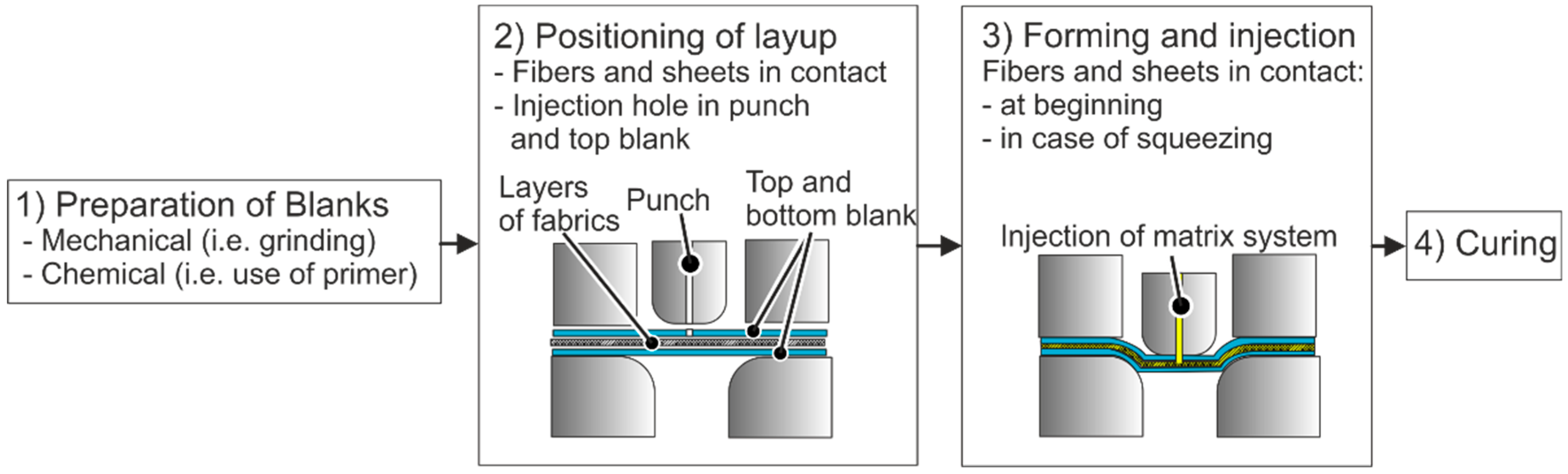
:1. Introduction
1.1. Symmetrical Layup
1.2. Unsymmetrical Layup
2. Aim and Approach
3. Materials Specifications
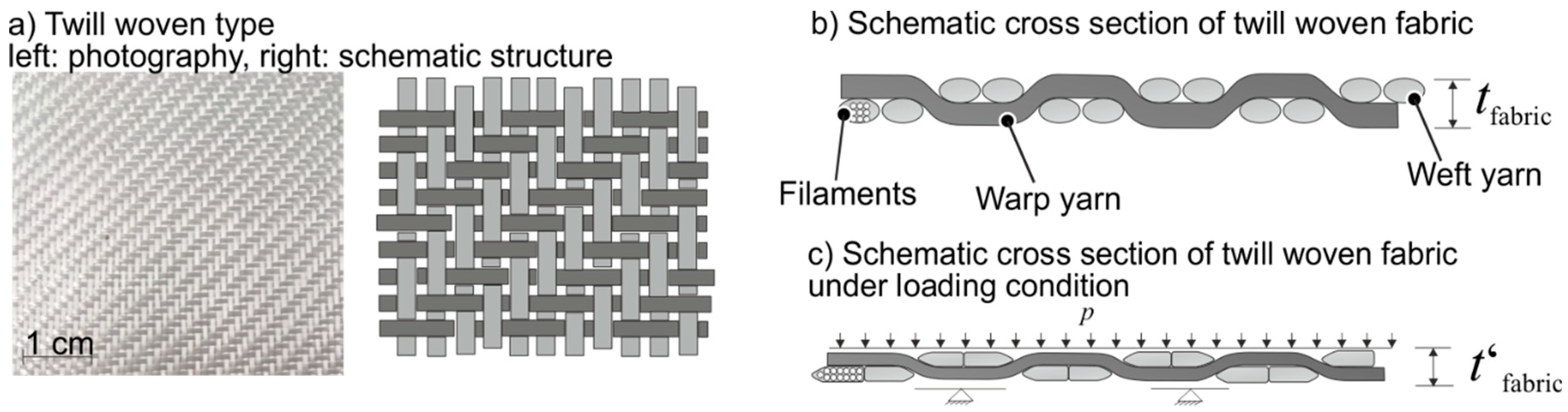
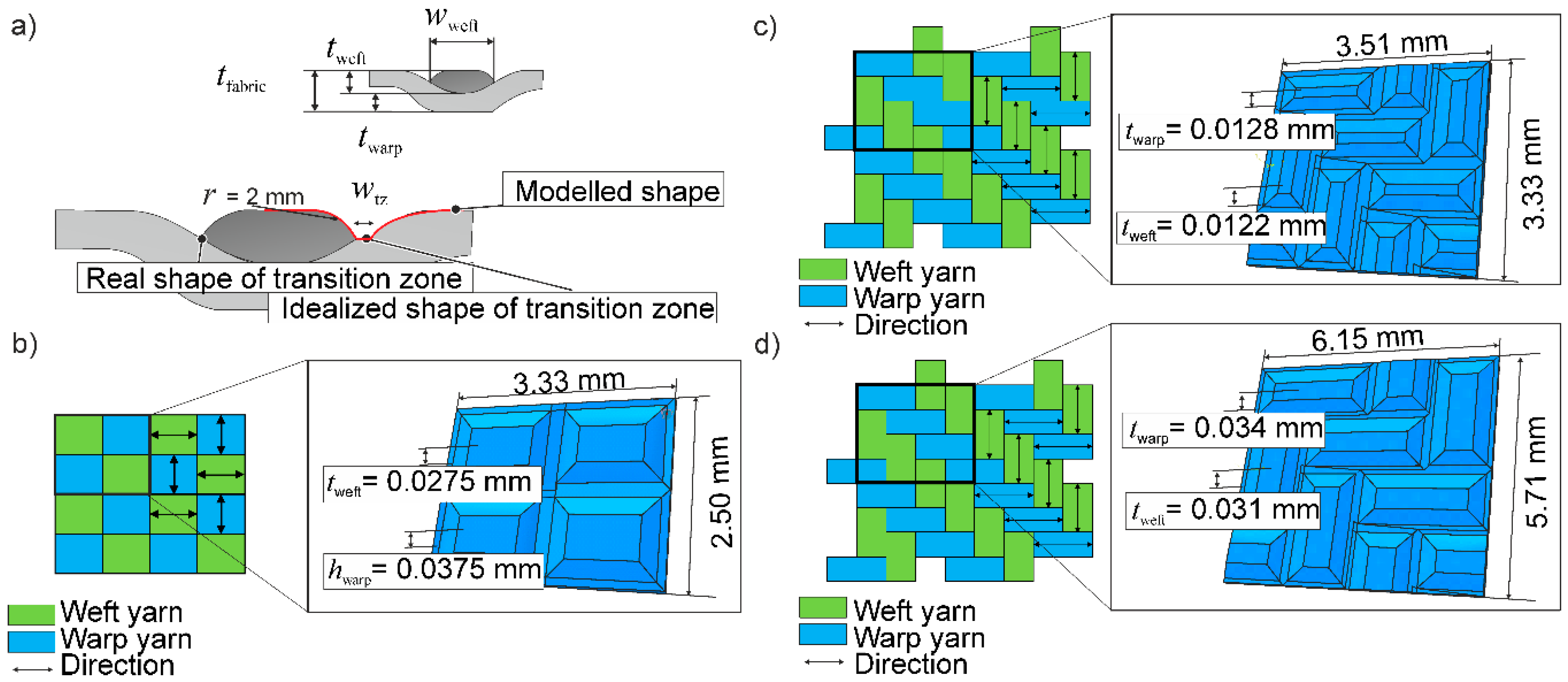
3.1. Twill Woven Fabric
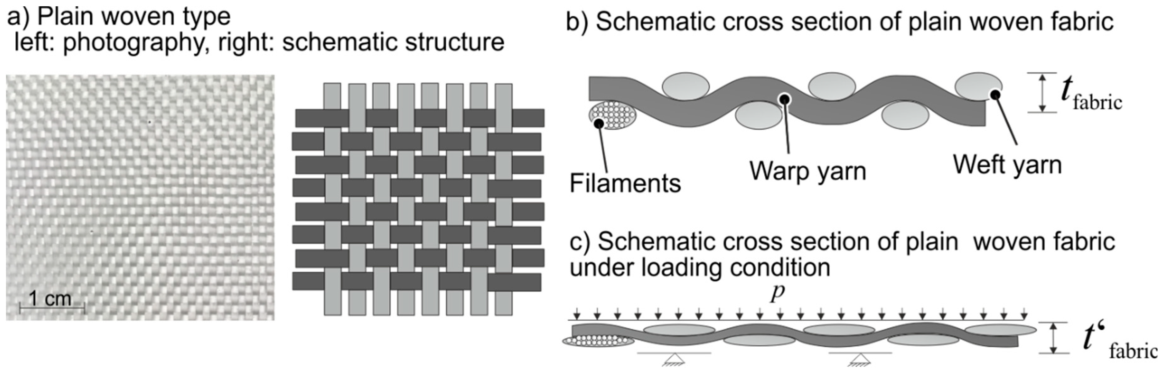
3.2. Plain Woven Fabric
4. Nakazima Tests
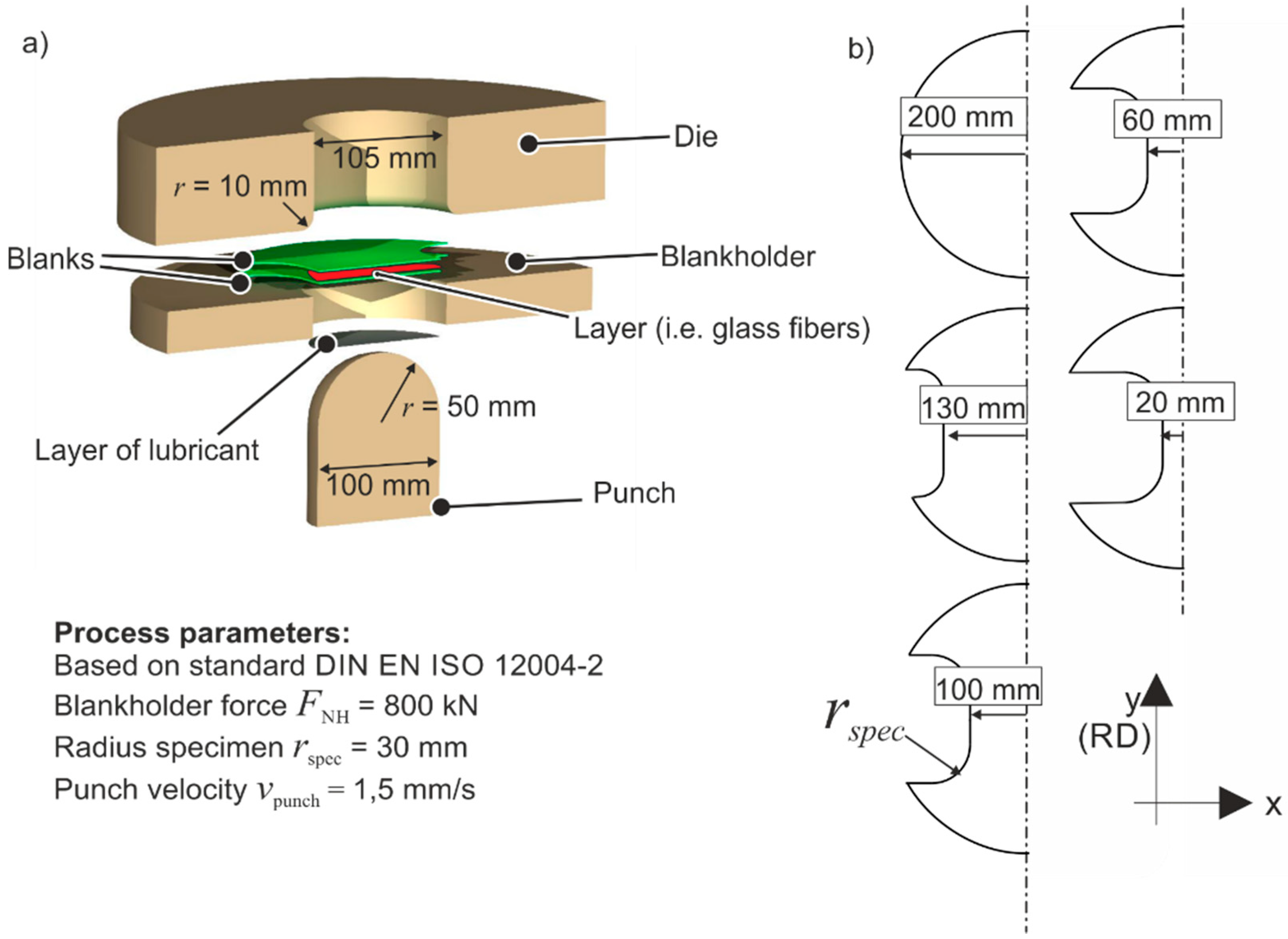
4.1. Experimental Setup
- Two sheets without layer in between
- Two sheets with lubricant in between (Grease, NLGI2 class)
- Two sheets with dry fibers in between (plain and twill woven)
- Two sheets with infiltrated (matrix system Elium 150) fibers in between (twill woven)
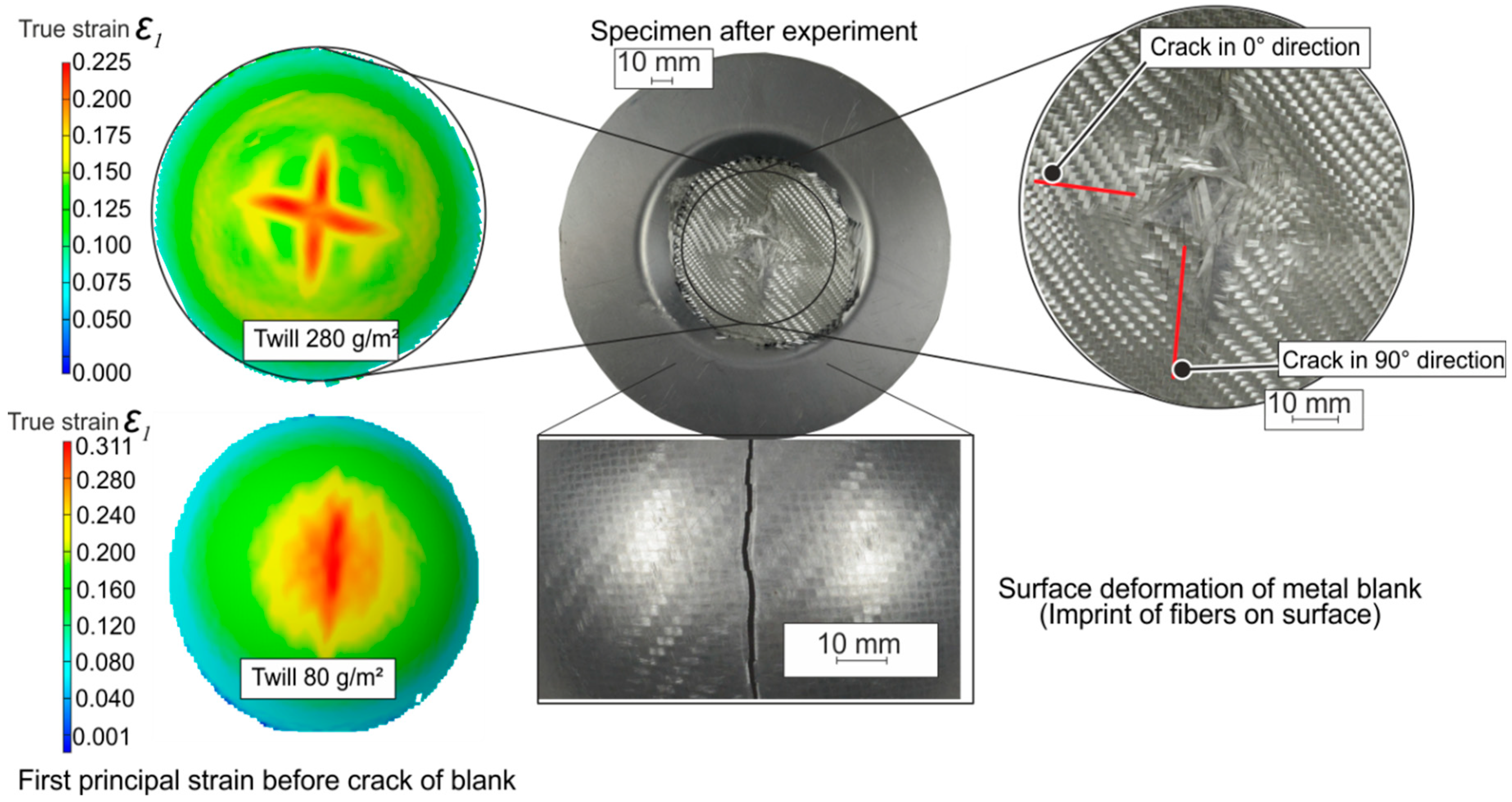
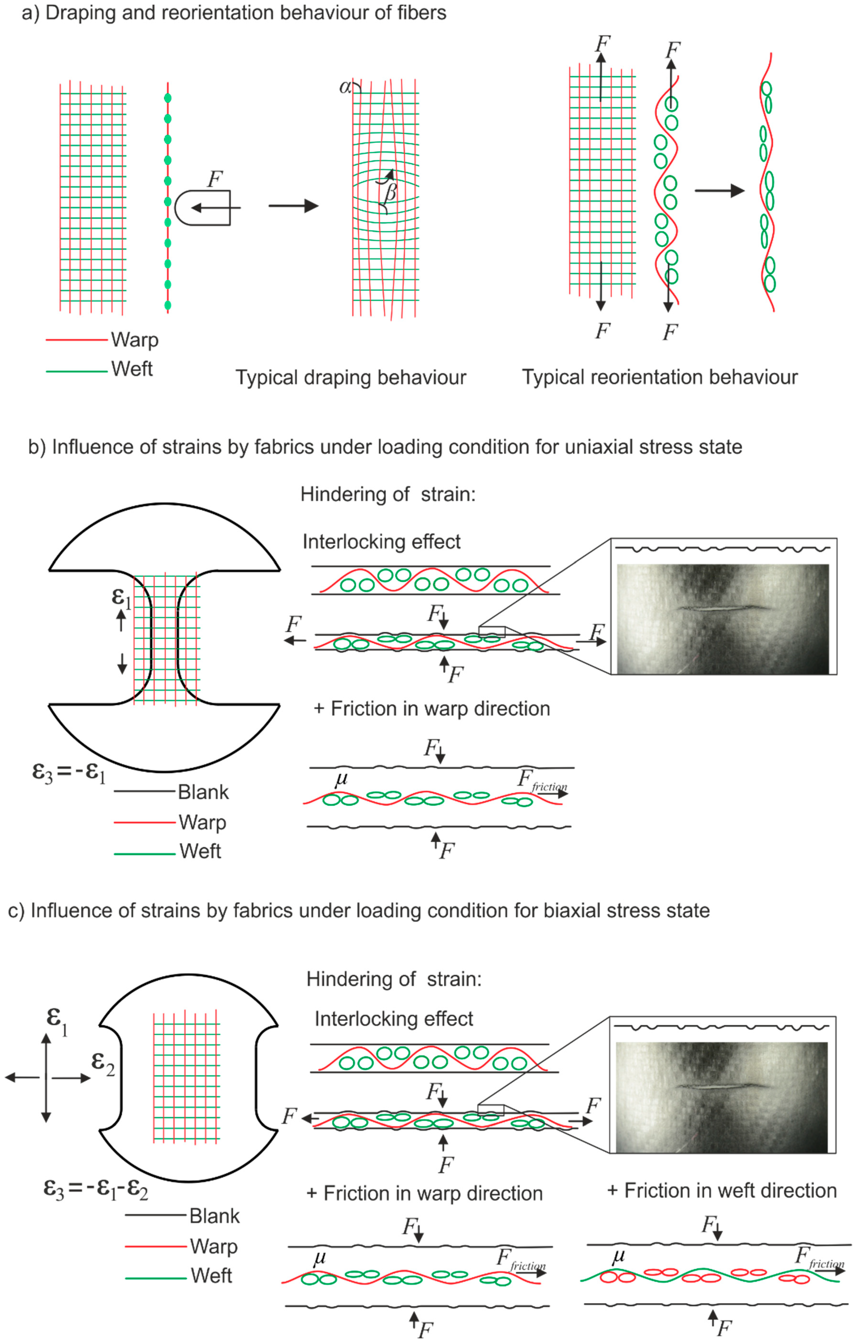
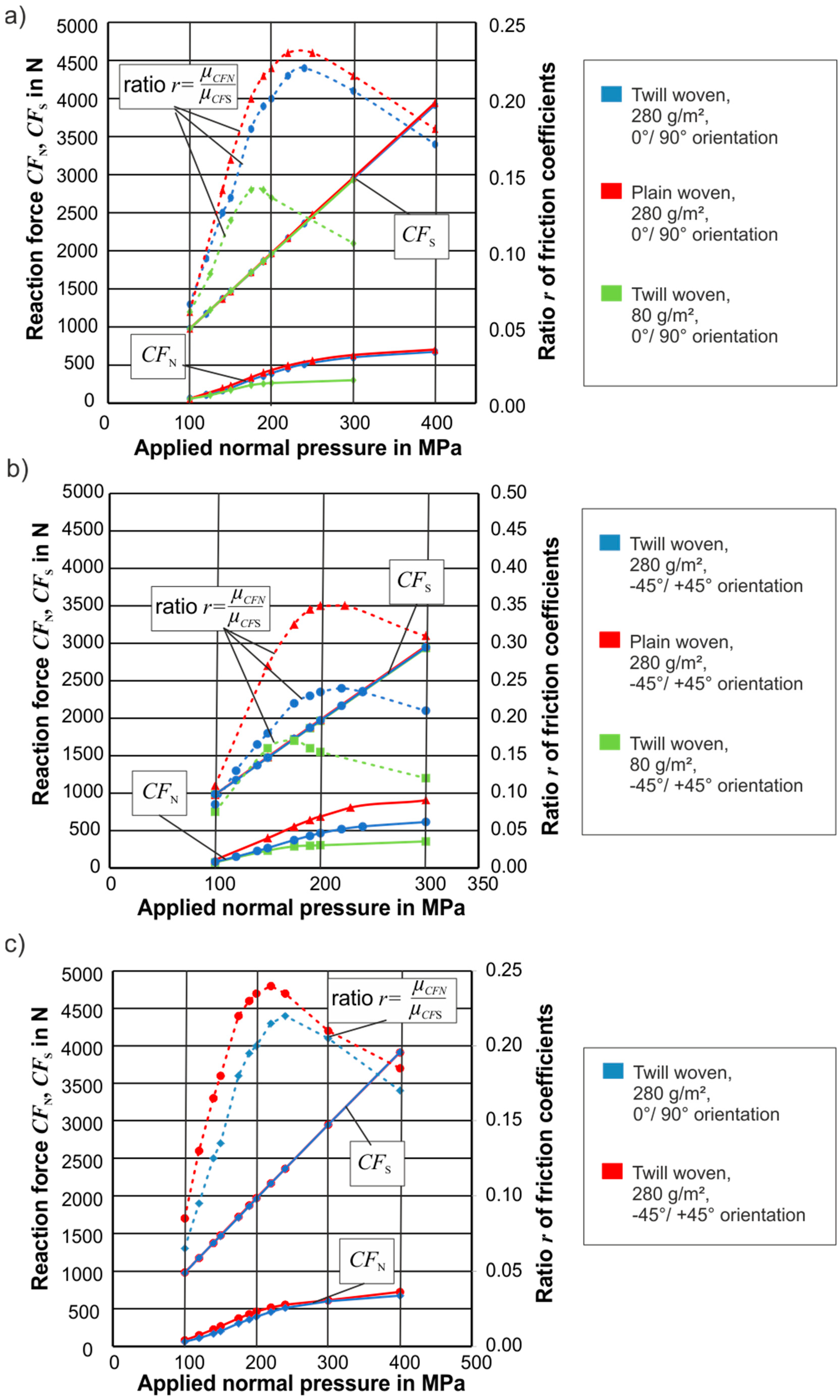
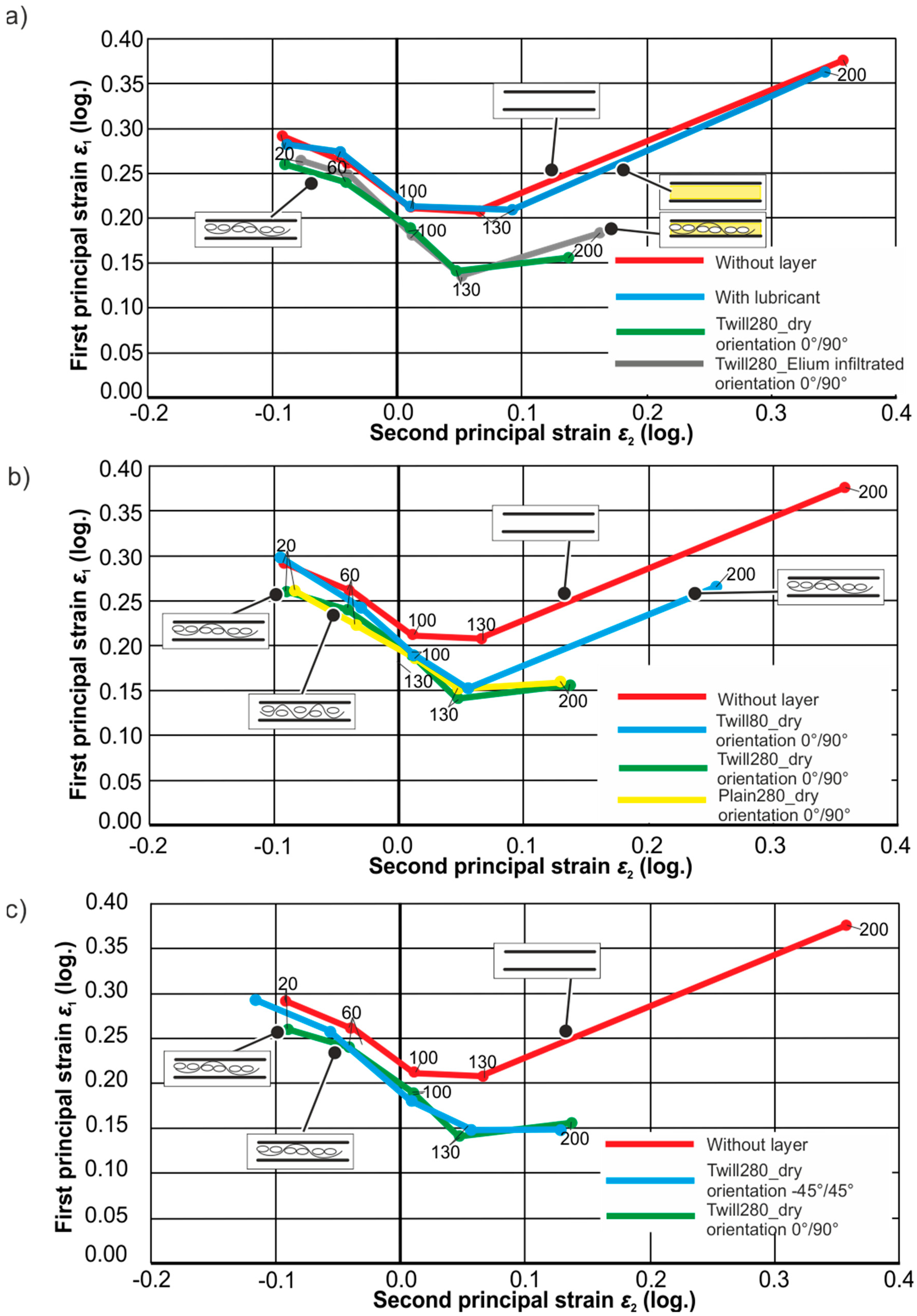
4.2. Results
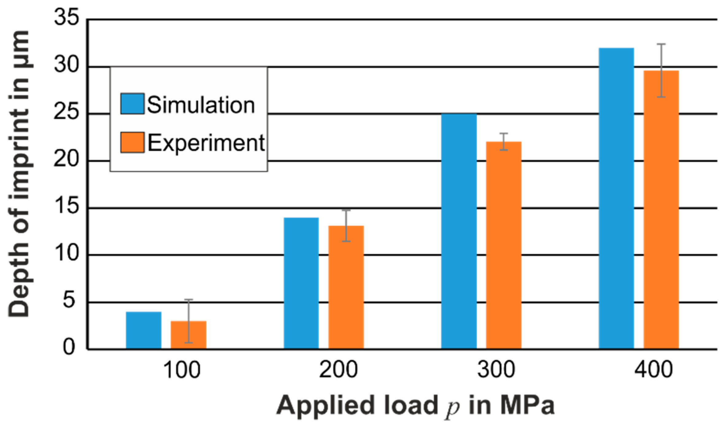
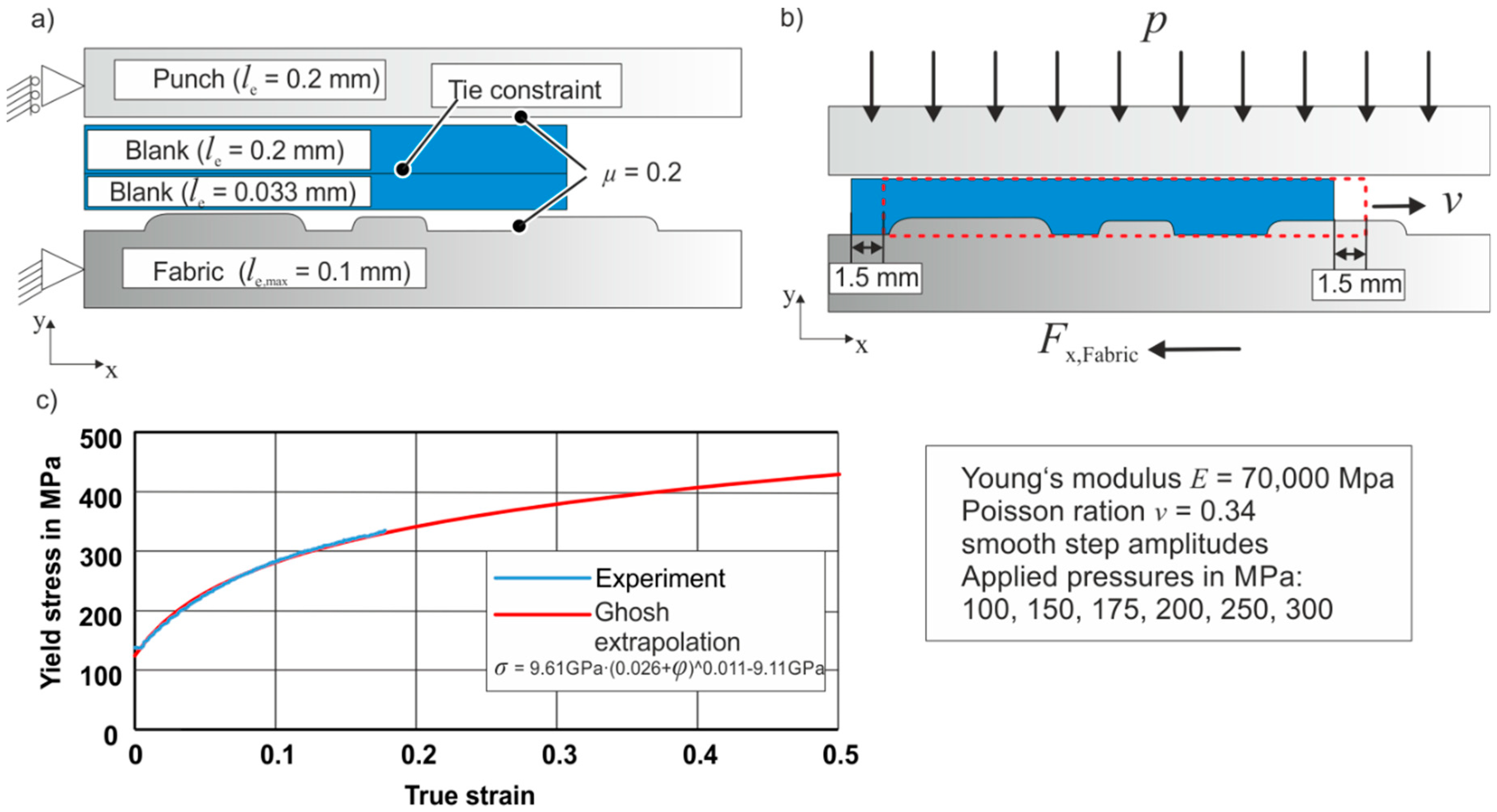
5. Numerical Investigations
6. Results
7. Conclusions
- high fiber volume fraction,
- high contact pressures, which lead to a squeezing out of the resin (polymer), and
- forming with dry fibers and postponed injection.
Author Contributions
Funding
Acknowledgments
Conflicts of Interest
References
- Vlot, A. Glare: History of the Development of a New Aircraft Material; Kluwer Academic Publishers: Dordrecht, The Netherlands, 2004; ISBN 978-1-4020-0124-6. [Google Scholar]
- Vogelesang, L.B. Development of a new hybrid material (ARALL) for aircraft structures. Ind. Eng. Chem. Prod. Res. Dev. 1983, 22, 492–496. [Google Scholar] [CrossRef]
- Vogelesang, L.B.; Gunnink, J.W. ARALL: A materials challenge for the next generation of aircraft. Mat. Des. 1986, 7, 287–300. [Google Scholar] [CrossRef]
- Miller, W.K. Metal-Plastic laminates for vehicle weight reduction. SAE Trans. 1980, 89, 481–490. [Google Scholar]
- Toshiaka, S.; Hiroyushi, N.; Hoshihiko, K.; Takenobu, S.; Hiroo, T.; Masatsuno, K. Metal-Resin-Metal Sandwich laminates Suitbale for Use in Working. Patent EP0115103A1, 24 January 1983. [Google Scholar]
- Soellart-Roelofsen, M.; Bottema, J. Metal-Polypropylene-Metal Laminate and Method of Making a Shaped Sheet Article of Such a Laminate. Patent EP0598428A1, 25 May 1994. [Google Scholar]
- Behrens, B.A.; Hübner, S.; Neumann, A. Forming Sheets of Metal and Fibre-reinforced Plastics to Hybrid Parts in One Deep Drawing Process. In Proceedings of the 11th ICTP 2014, Nagoya, Japan, 19–24 October 2014; Volume 81, pp. 1608–1613. [Google Scholar]
- Dau, J.; Lauter, C.; Damerow, U.; Homberg, W.; Tröster, T. Multi-material systems for tailored automotive structural components. In Proceedings of the 18th ICCM, Jeju Island, Korea, 21–26 August 2011. [Google Scholar]
- Wollmann, T.; Hahn, M.; Wiedemann, S.; Zeiser, A.; Jaschinski, J.; Modler, N.; Ben Khalifa, N.; Meißen, F.; Paul, C. Thermoplastic fibre metal laminates: Stiffness properties and forming behaviour by means of deep drawing. Arch. Civ. Eng. 2018, 18, 442–450. [Google Scholar] [CrossRef]
- Lee, M.S.; Kim, S.J.; Lim, O.D. The effect process parameters on epoxy flow behavior and formability with CR340/CFRP composites by different laminating in deep drawing process. J. Mater. Process. Technol. 2016, 229, 275–285. [Google Scholar] [CrossRef]
- Wang, Z.; Lauter, C.; Sanitther, C.B.; Frantz, M.; Tröster, T. Intrinsic-manufacturing of metal-FRP-hybrid structural automotive components by resin transfer moulding. In Proceedings of the 18th ICCS, Lisbon, Portugal, 15–18 June 2014. [Google Scholar]
- Mennecart, T.; Werner, H.; Ben Khalifa, N.; Weidenmann, K.A. Developments and analyzes of alternative processes for the manufacturing of fiber metal laminates. In Proceedings of the MSEC 2018, College Station, TX, USA, 18–22 June 2018. [Google Scholar] [CrossRef]


| Specific Weight in g/m2 | Yarn Description and Thread Count | Thickness tfabric of Fibers (Measured) | Compacted Thickness t′fabric of Fibers (Measured) |
|---|---|---|---|
| 280 | Warp yarn: EC 9–68 tex x3 t0; 7 yarn/cm | 0.23 mm | 0.13 mm |
| Weft yarn: EC 9–204 tex; 6.5 yarn/cm | |||
| 80 | Warp yarn: EC 9–34 tex; 12 yarn/cm | 0.07 mm | 0.05 mm |
| Weft yarn: EC 9–34 tex; 11.4 yarn/cm |
| Specific Weight in g/m2 | Yarn Description and Thread Count | Thickness tfabric of Fibers (Measured) | Compacted Thickness t′fabric of Fibers (Measured) |
|---|---|---|---|
| 280 | Warp yarn: EC 11–204 tex, 8 yarn/cm Weft yarn: EC 11–204 tex, 6 yarn/cm | 0.23 mm | 0.13 mm |
© 2019 by the authors. Licensee MDPI, Basel, Switzerland. This article is an open access article distributed under the terms and conditions of the Creative Commons Attribution (CC BY) license (http://creativecommons.org/licenses/by/4.0/).
Share and Cite
Mennecart, T.; Gies, S.; Ben Khalifa, N.; Tekkaya, A.E. Analysis of the Influence of Fibers on the Formability of Metal Blanks in Manufacturing Processes for Fiber Metal Laminates. J. Manuf. Mater. Process. 2019, 3, 2. https://doi.org/10.3390/jmmp3010002
Mennecart T, Gies S, Ben Khalifa N, Tekkaya AE. Analysis of the Influence of Fibers on the Formability of Metal Blanks in Manufacturing Processes for Fiber Metal Laminates. Journal of Manufacturing and Materials Processing. 2019; 3(1):2. https://doi.org/10.3390/jmmp3010002
Chicago/Turabian StyleMennecart, Thomas, Soeren Gies, Noomane Ben Khalifa, and A. Erman Tekkaya. 2019. "Analysis of the Influence of Fibers on the Formability of Metal Blanks in Manufacturing Processes for Fiber Metal Laminates" Journal of Manufacturing and Materials Processing 3, no. 1: 2. https://doi.org/10.3390/jmmp3010002
APA StyleMennecart, T., Gies, S., Ben Khalifa, N., & Tekkaya, A. E. (2019). Analysis of the Influence of Fibers on the Formability of Metal Blanks in Manufacturing Processes for Fiber Metal Laminates. Journal of Manufacturing and Materials Processing, 3(1), 2. https://doi.org/10.3390/jmmp3010002