1. Introduction
As an important energy conversion mechanism, centrifugal compressors play an important role in the national economy such as electricity, oil, and natural gas [
1]. The blade is a key component of the compressor, and the material and processing costs are high. For example, the material and processing cost of the nickel 718 blade with a diameter of about 400 mm is more than one hundred thousand dollars. Blades that operate in harsh service environments are prone to fatigue, wear, corrosion, and the like. If such an expensive impeller is directly scrapped due to damage, it will not only cause complete loss of remanufacturing value, but also cause huge downtime economic loss due to the new impeller manufacturing cycle. For example, the centrifugal compressor for natural gas transmission has a shutdown loss of up to 1.46 million dollars per day.
With the promotion of the sustainable development strategy, remanufacturing research on damaged and retired impellers/blades containing high additional value is getting more and more attention, which is one of the effective ways to make full use of remanufacturing resources and solving the problem of natural resource deficiency. There is some early research on blades repaired using traditional repair technologies, such as plasma transferred arc (PTA) welding [
2], gas tungsten arc welding [
3], tungsten inert gas (TIG) welding [
4], etc. However, these conventional techniques also have significant technical disadvantages, such as huge heat input to the base material, hot-cracking in the welded layers, and low bonding force between the coating and the substrate.
As a revolutionary foreword technology, additive manufacturing (AM) has received worldwide attention and rapid growth. As one of the typical technologies for AM, laser additive manufacturing (LAM), also known as laser direct deposition, has become an effective method to manufacture metal parts [
5]. Some scholars have conducted research on remanufacturing using LAM technology such as laser direct deposition, laser cladding, etc. Gao et al. [
6] and Yilmaz et al. [
7] presented an integrated adaptive repair solution for complex aerospace blades based on laser cladding repair. Gong et al. [
8] studied on the research of TC11 titanium alloy components repaired by the laser melting deposition process and pointed out that the damaged impeller blades pass the over speed test after machining and checking. Shi et al. [
9] used laser cladding with Ni based powder as cladding material to repair 45 damaged steel gears, with synchronous powder feeding and gear axial scanning method, and found the laser cladding method could repair the gear surfaces and raise the wear resistance to obtain high strength cladding layers on damaged gears’ teeth surfaces. Vedani [
10] investigated the microstructural behavior of steel tools after repairing, welding or refurbishing by a pulsed Nd-YAG precision laser and found the welded metal regions had a significantly finer structure with respect to the GTAW welded materials. Paydas et al. [
11] studied the effect of building strategy and incident energy on the metallurgical characteristics of the repairs in relation to their complex thermal history.
Reverse engineering (RE) is a design process which is relative to traditional forward engineering, from sample physical to three-dimensional digital models then to final products. Some scholars have used reverse engineering techniques to study the reverse modeling of blades and other parts. Zhang et al. [
12] presents a damage reconstruction method based on tri-dexel modeling for laser-aided repairing of metallic components. Wang [
13] applied the optical three-dimensional scanning system to obtain the point cloud data of high-strength steel sheet parts, and obtained the three-dimensional model of the parts through reverse engineering through data processing. Li et al. [
14] used Geomagic studio to perform point cloud merging, streamlining, denoising, and surface fitting on the point cloud data, and generated the surface model of motorcycle parts. Xie et al. [
15] achieved model reconstruction in the technology integration environment and completed the impeller model reconstruction based on reverse engineering software, Geomagic studio combined with Ansys, MATLAB, and UG software.
At present, a large number of studies in LAM and RE are isolated. When the two methods are combined, they become a remanufacturing technology based on LAM and RE aimed at restoring a part’s geometric size and optimizing the organization. Only a few scholars have combined the two methods to conduct research. Zhang et al. [
16,
17] reconstructed the engine blade model using reverse engineering and simulated the surface wear of the blade by the laser direct deposition technique. Wilson et al. [
18] demonstrated a successful repair of defective voids in turbine airfoils based on a new semi-automated geometric reconstruction algorithm and a laser direct deposition process.
The literature review shows that the studies on the subsequent machining of LAM forming layer are rare in existing remanufacturing based on LAM and RE. Subsequent processing to remove excess material is necessary to restore the geometric accuracy of the parts and meet the assembly requirements. Therefore, laser additive and milling subtractive composite manufacturing technology is an effective method to remanufacture metal parts. In this paper, based on the foundation studied on KMN steel laser cladding repairing [
19] and milling characteristics of the LAM forming layer [
20], a methodology for the compressor blade remanufacturing via reverse engineering, free-form surface modelling, laser direct deposition, and multi-axis machining was presented. The methodology was implemented on thin-curved centrifugal compressor blades, which is made by KMN steel. The experimental results were analyzed and are demonstrated in this paper.
2. Materials and Methods
2.1. Remanufacturing Strategy
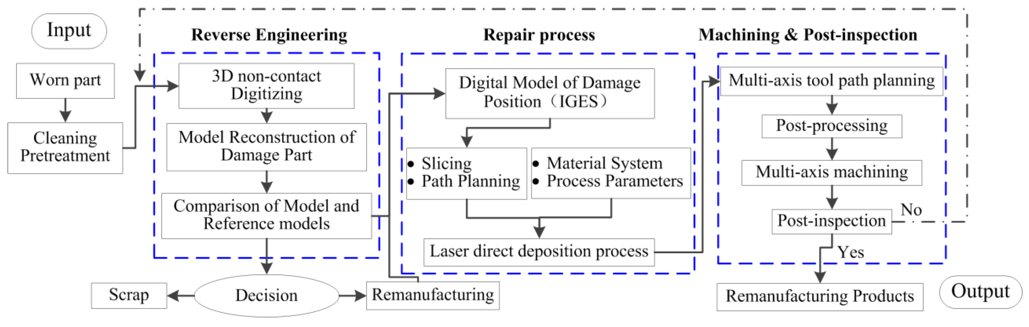
The proposed remanufacturing system consists of a chain of different processes. The general structure of the proposed remanufacturing system based on reverse engineering (RE) technology, LAM and, subsequent machining is shown in
Figure 1. Using the 3D non-contact laser scanner system, the blade geometry data of polygon mesh format is quickly obtained through multi-view alignment, data filtering, and triangulation. In addition, a high-quality polygon mesh with no defects in the polygon modeling environment is created by the scanned data. Geometry reconstruction, based on RE system, was used to generate paths for laser direct deposition and subsequent milling subtractive in a CAD/CAM system (such as UG NX software). For complex components, the three-axis machining path for laser additive forming can be created in the reverse engineering module based on additional patch. Five-axis tool paths for milling subtractive manufacturing can be created based on the subtractive patch. By post-processing the generated toolpath, a CNC code (such as a G code) can be generated to drive the machine.
2.2. 3D Digitizing System
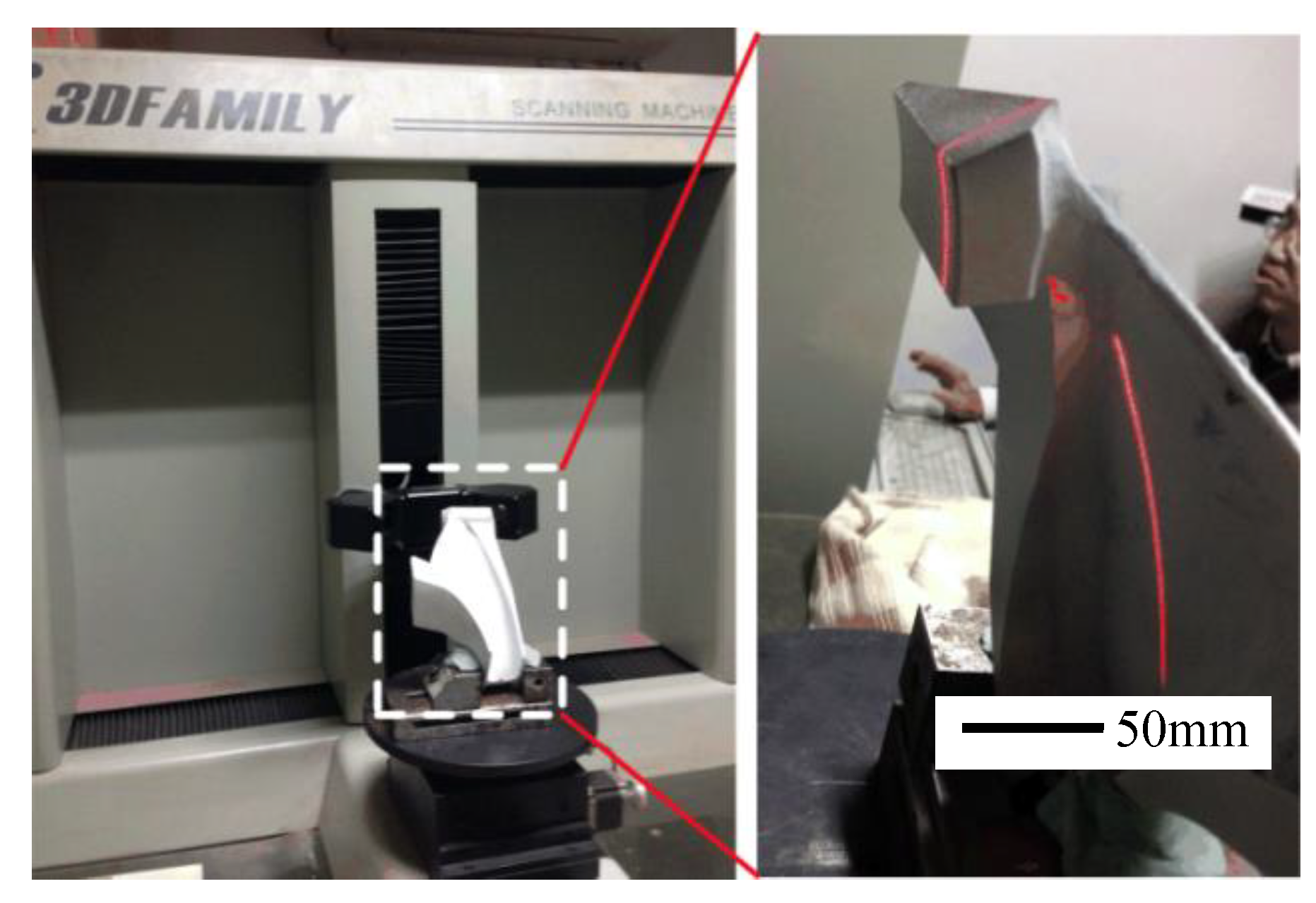
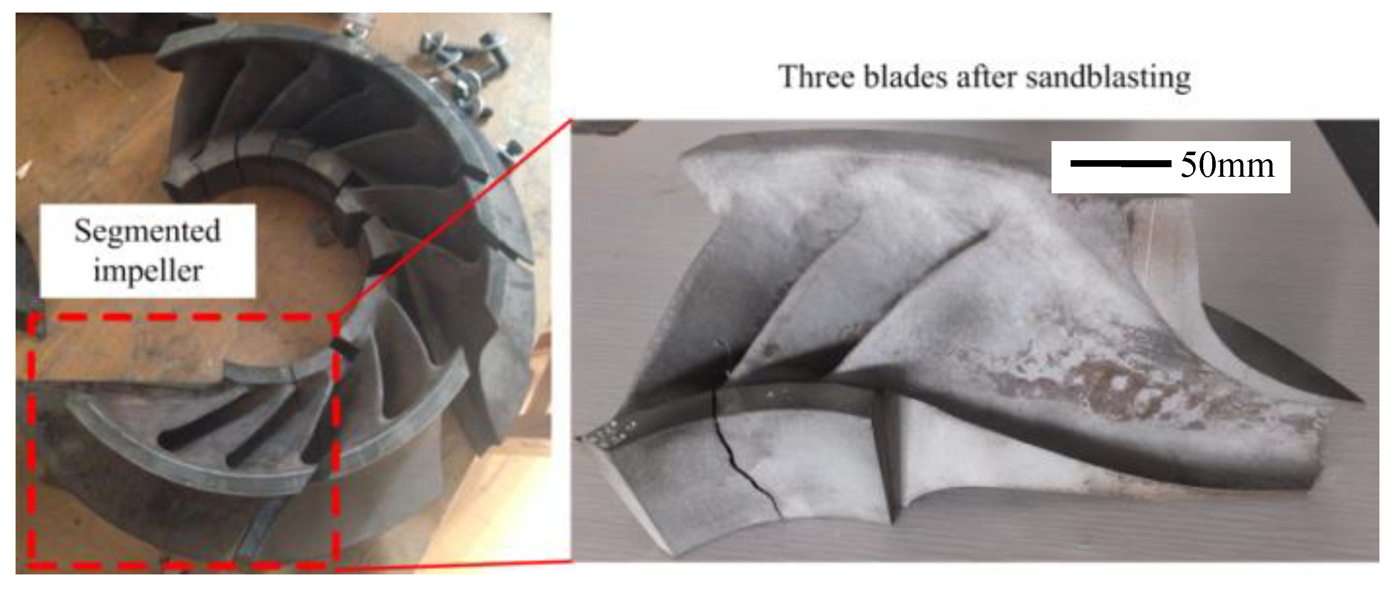
It is well known that compressors have a harsh service environment and, after long periods of operation, the blades often have deformation, tearing, and other defects. Therefore, the damage of the blade has many forms. In order to solve the difficulties caused by different forms of damage, and the part-to-part variation, the blade remanufacturing process must be able to adapt to each physically worn blade, which makes the acquisition of geometrical data an essential process. Therefore, 3D model reconstruction in blade remanufacturing requires a suitable digital system to provide sufficient and accurate data. In this work, a 3D Family laser scanner machine was chosen to scan worn blades, taking into account factors such as blade size, accuracy, scanning speed, data processing speed, and recovered blade data quality. The main parameters are shown in
Table 1. The blade scanning process is shown in
Figure 2.
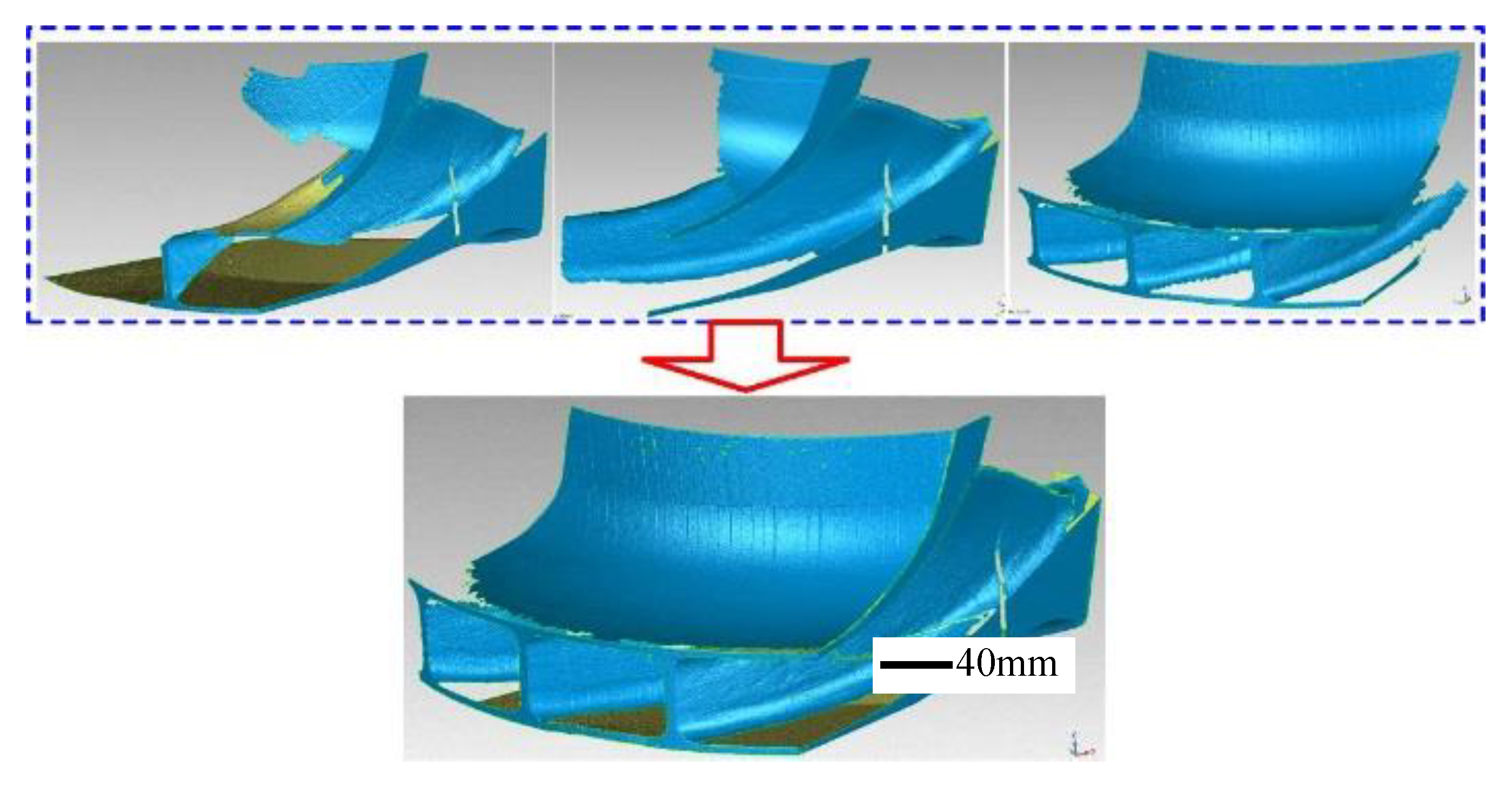
Due to the complexity of the blade structure, it is difficult to obtain enough data for model reconstruction in a single scan. Therefore, it is necessary to scan the blades in all directions and then align these scanned data sets into a complete model. Thus, the single blade and three blades’ parts were scanned and the point cloud data were obtained respectively.
Unexpected errors can occur during scanning due to unexpected light interference, sharp edges, and invisible occlusion surface areas, which can result in inaccurate scan data. In addition, the alignment process may result in anomalous triangles due to data overlap and holes or gaps between different data blocks. This will also affect the accuracy of data. Therefore, it is necessary to preprocess the data obtained by the scan, thereby deriving the corrected scan model. In fact, the editing process of this raw scan data can be implemented by commercial reverse engineering software, such as Geomagic Studio, which can usually be used to eliminate errors in the original data produced by the scanning process [
21]. The multi-angle scanning process, the original data correction process, and the blade model reconstruction process of the damaged compressor blade are as follows:
Step 1: Filtering of the point cloud data. During the scanning process, due to slight vibration of the scanning device, inaccurate scanning calibration, and the influence of background and lighting, it is possible to generate a certain amount of yawp points, which may cause large errors in the reconstruction work and should be cleared before reconstruction.
Step 2: Multi-viewed piecing-together. Since multiple scans were performed on irregular surfaces and places with large curvature during the scanning process, multiple point clouds were generated. It needs to splice multi-view data points, which will obtain the preliminary blades model.
Step 3: Delete abnormal topological triangles that appear in the model. Surface-triangular patches with poor local scan quality and particularly poor surface roughness should be partially smoothed.
Step 4: Fill holes and gaps. In this work, most of the holes and gaps have no significant effect on laser direct deposition repairing, so it is just needs a simple filling operation.
Step 5: Optimize and subdivide the model. If the point cloud data is too large, the computer will slow down when processing the point cloud data. In this case, the point cloud data needs to be sampled, as long as the necessary point cloud data is retained.
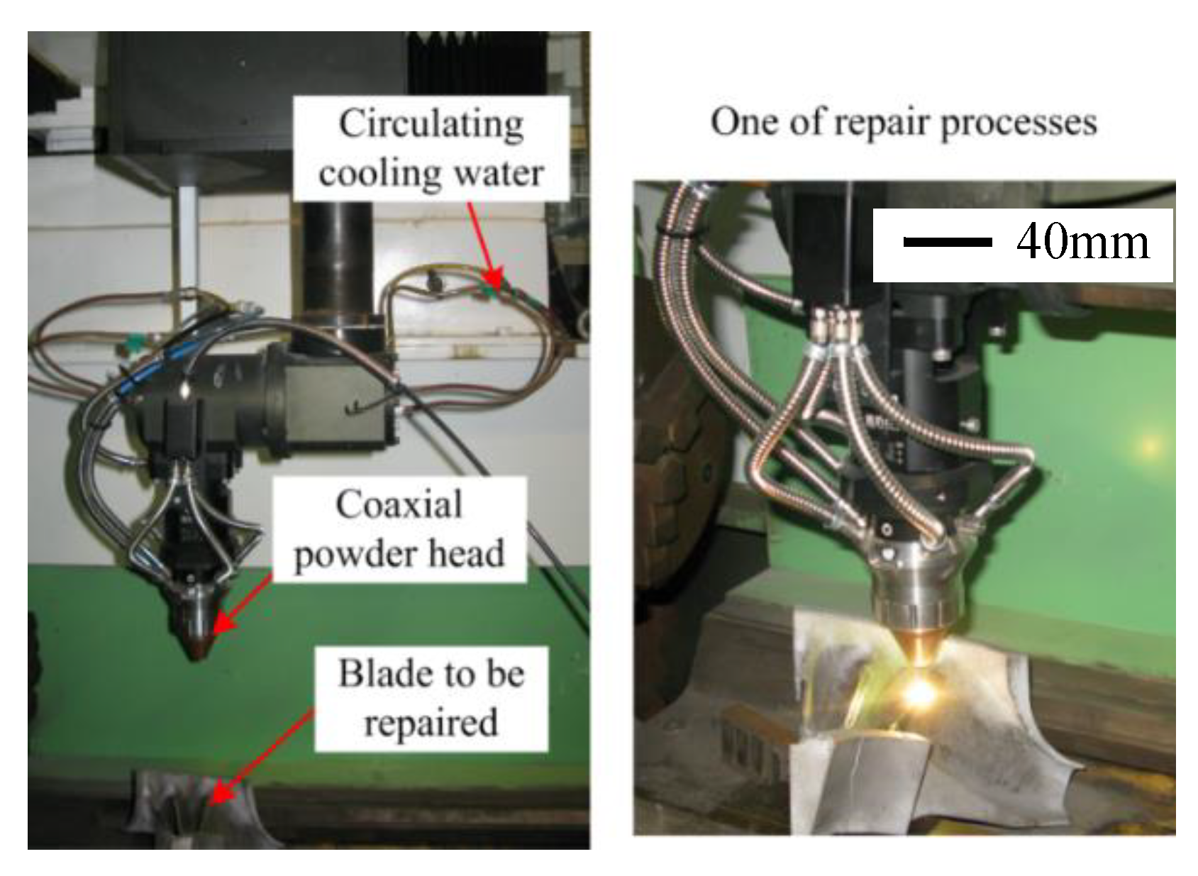
2.3. LAM Repaired Process
The LAM process was performed using a CO
2 multimode cross-flow laser operating with a coaxial powder head at output power of 4 kW with a 3-mm beam diameter. The beam scanning speed was 500 mm/min. FeCr alloy powder containing 1.5% wt La
2O
3 was used in this study. The compositions of FeCr alloy mixture and the KMN steel are indicated in
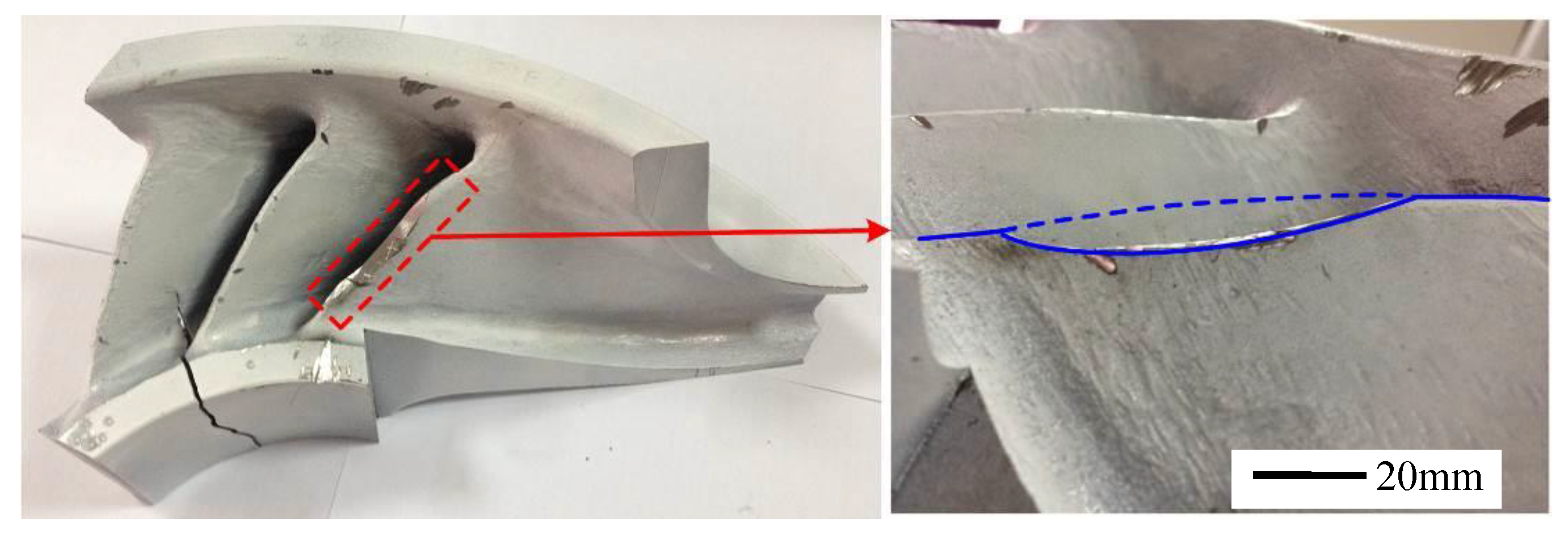
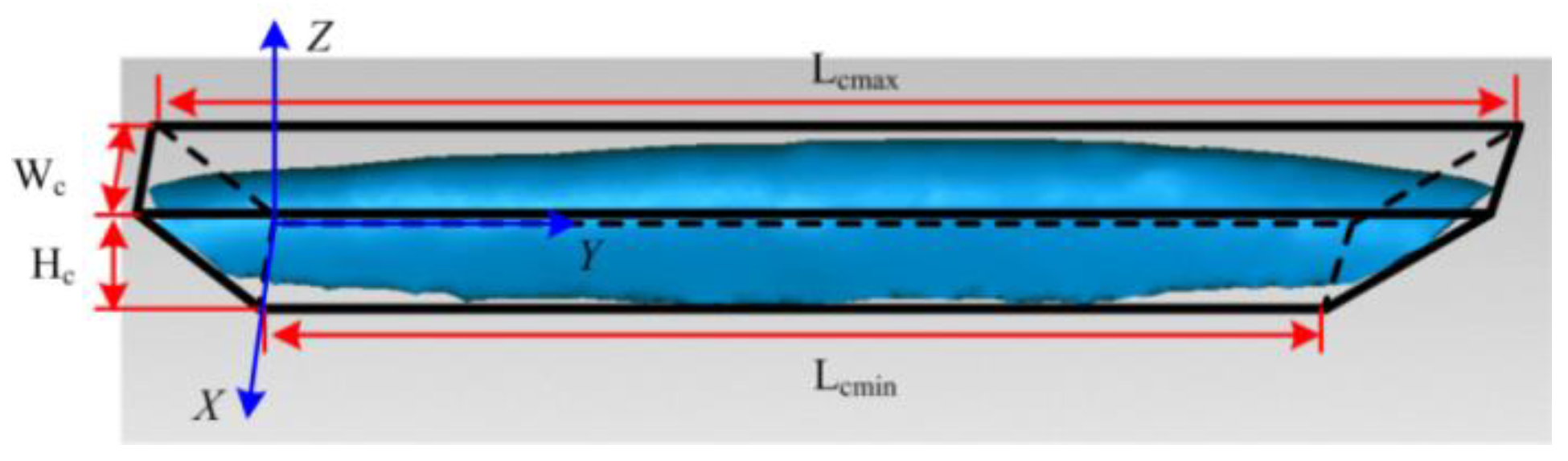
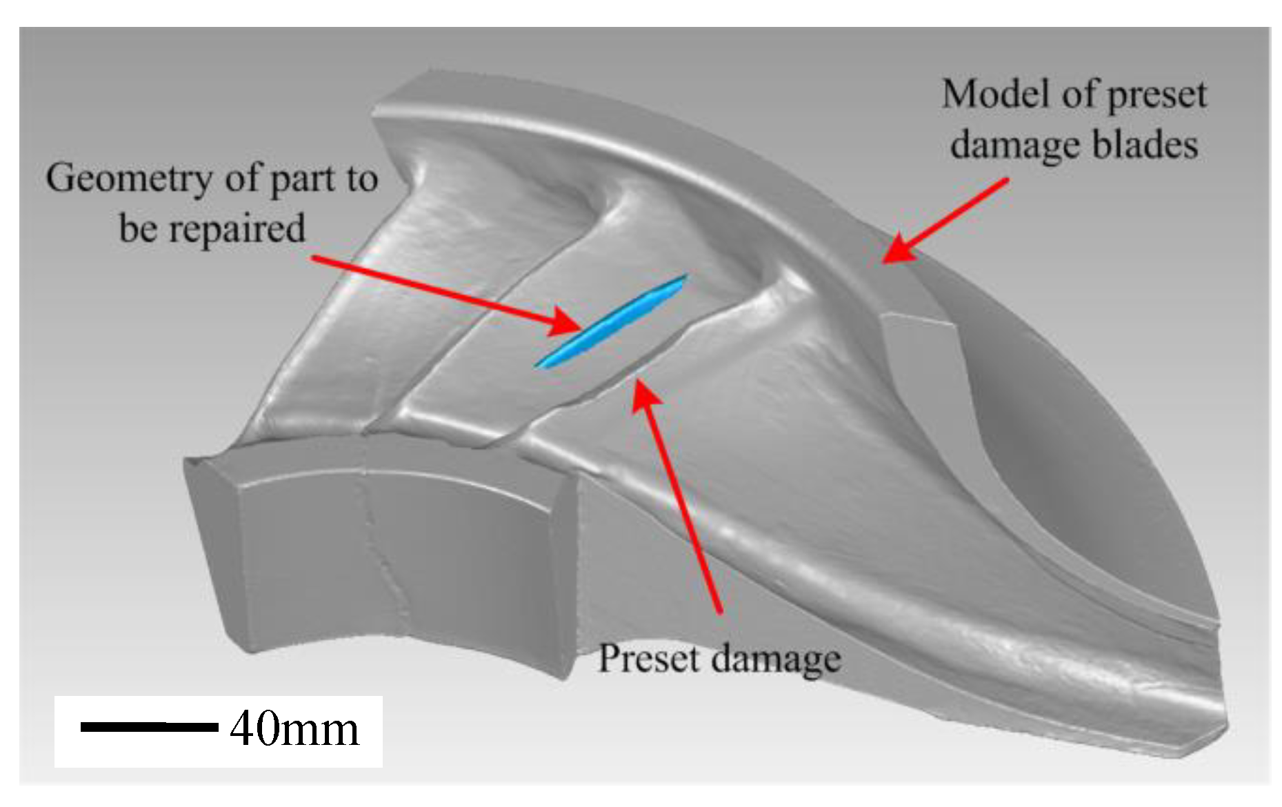
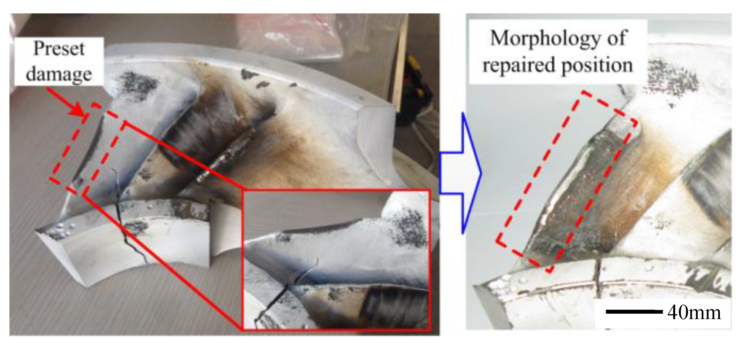
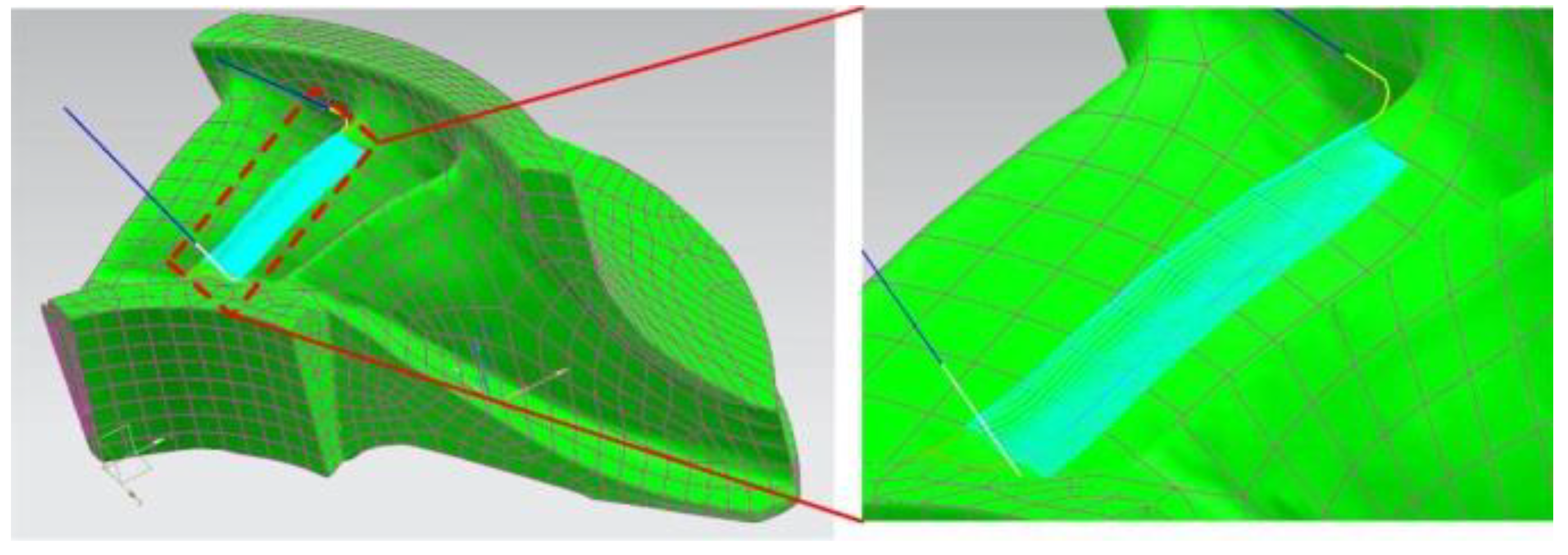
Table 2. The powder flow rate was 13.1 g/min. The geometry of the part to be repaired is shown in the blue part of
Figure 3. In order to facilitate the planning of the laser repair path, the geometry is simplified, as shown by the thick black line in
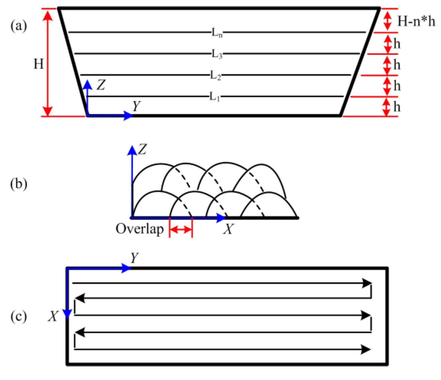
Figure 3. According to the simplified model of damage position, at the end of each layer the Z height was adjusted automatically. And the laser beam scanning was reciprocating scanning in each layer, as shown in
Figure 4. The LAM process is shown in
Figure 5.
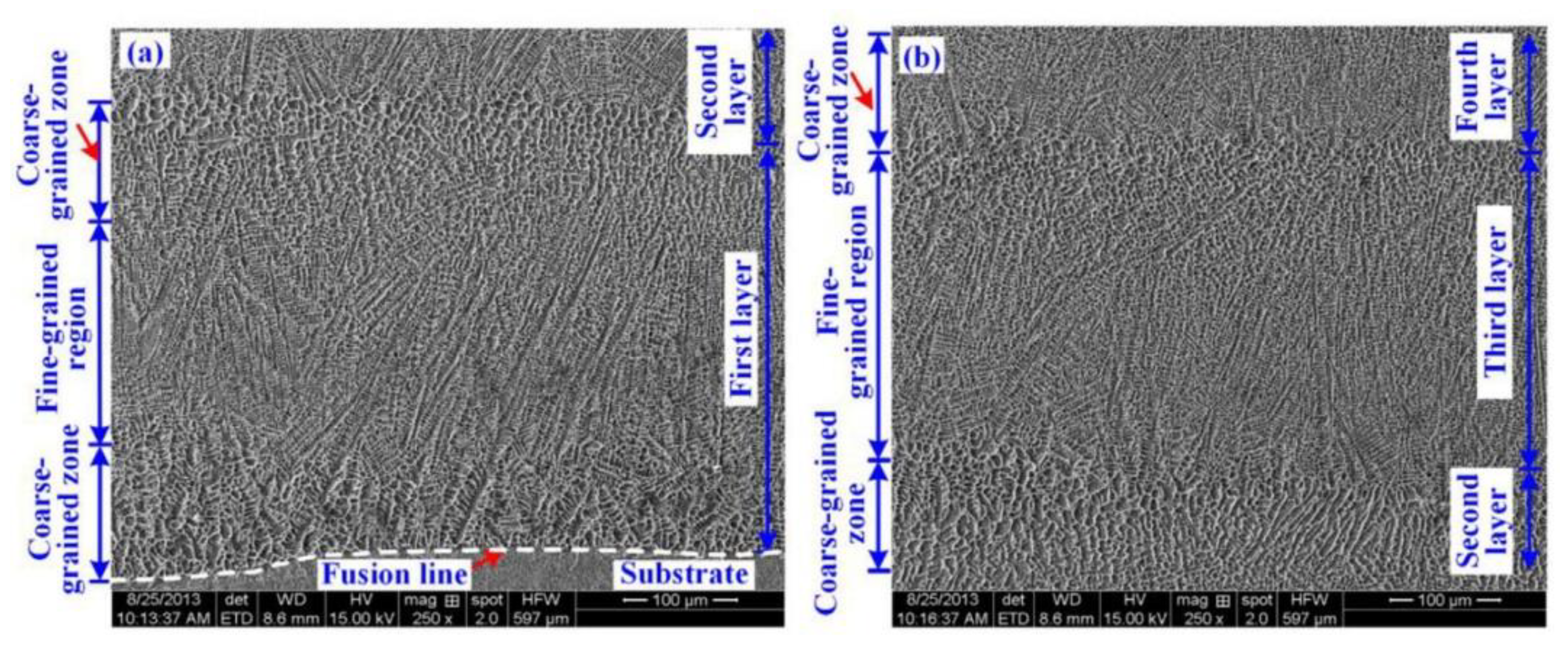
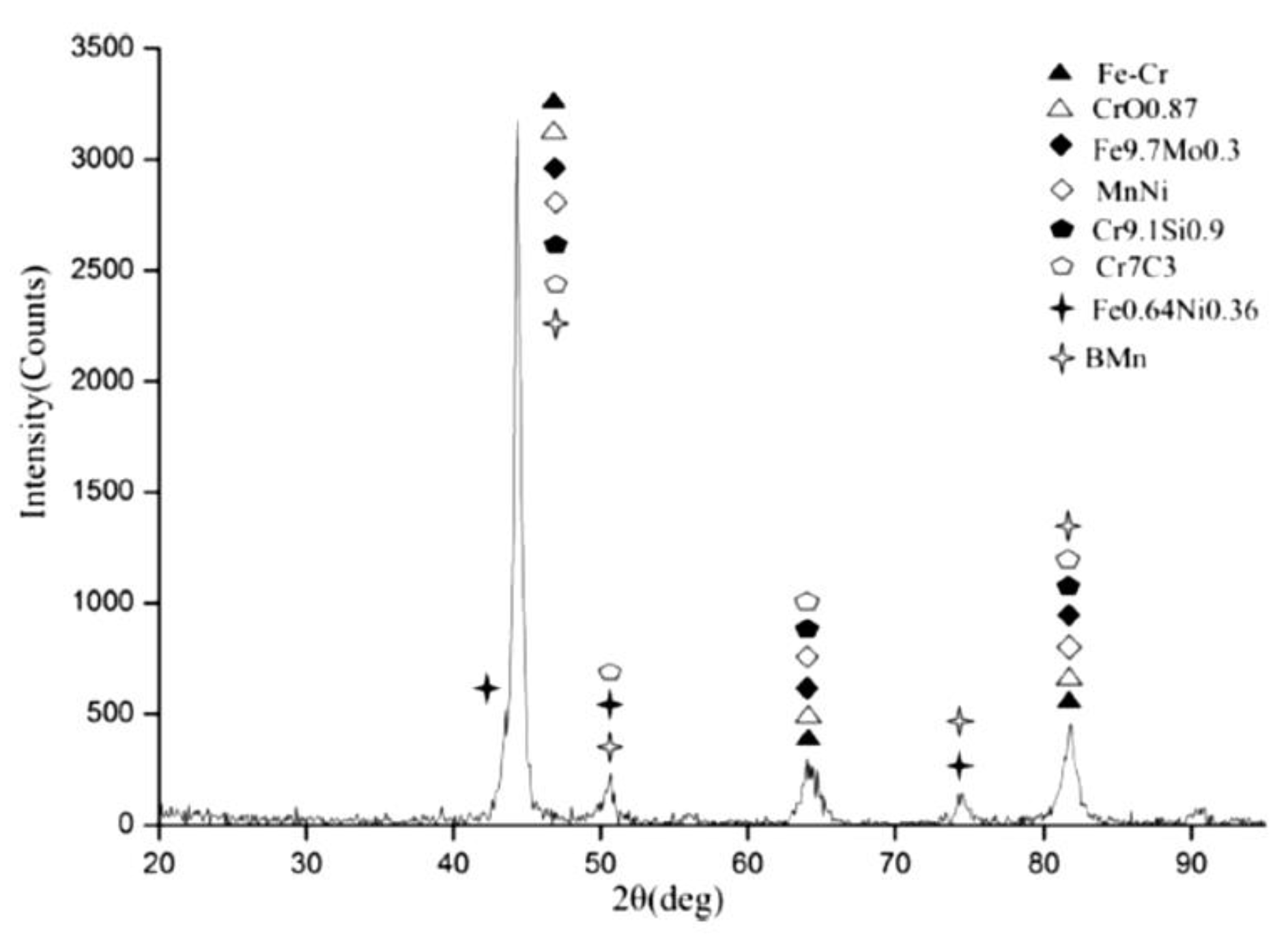
The microstructure and phase composition of the laser additive forming layer was tested and analyzed by a scanning electron microscope (SEM) and X-ray diffractometer (XRD). Based on the measured XRD pattern, phase identification was performed using MDI JADE software. The microhardness, wear resistance, and corrosion resistance had been investigated and published [
19].
4. Machining Strategy
To ensure that the parts repaired by laser cladding are restored to the accuracy requirements of the design, the LAM repaired part needs to be machined. The purpose of the research processing strategy is to remove the excess material most efficiently from the repaired part and to obtain the desired geometric properties (size requirements, surface characteristics). In addition, the problems of interference, collision, overcutting, etc., which often occur during the cutting process, are also considered and solved in the proposed processing strategy. The UG NX processing module provides the user with an identical, user-friendly graphical window environment. The user can observe the movement of the tool along the trajectory in graphical mode and can graphically modify it. Therefore, UG NX was selected to generate the tool path for milling the LAM parts. The reconstructed blade model of the IGES format was used in the process of generating the tool path.
For the side milling operation, the VARIABLE_ CONTOUR method was applied. In this case, machining features are the blade repaired position, as shown in
Figure 13. Machining tool paths generated are shown in the blue lines in
Figure 14, which are outputted as the ISO APT format and post processed as G-code for milling operation performed on a five-axis machining center.
Based on machining trials for the LAM forming layers [
20], a solid cemented carbide end mill with four cutting edges was used in this work. And the diameters (D) of the tools are 10 mm with equal overhang length. This end mill is highly precise and ensures very tight tolerances on the machined surface. The geometry of this end mill also has some benefits for the processing of LAM repaired blades. For example, a relatively short contact length will effectively reduce the deflection of the end mill. In addition, the blade tip geometry is twisted. Considering the tool-workpiece collision factor, the spherical shape end mill is the perfect choice for machining this geometry, although the overall depth of cut is not too large. Therefore, a 10 mm diameter ball-end solid carbide end mill with four cutting edges was selected for removing deposits from the LAM repair position of the blade.
The TOM five-axis machining center was selected for milling subtractive operations, which has an interchangeable palletizing system. The initial parameters used for milling and operation were obtained by taking the recommended parameters of the tool manufacturer and the machine tool builder into account. Then it was improved throughout the test based on actual processing quality. The purpose of this study was to remove redundant material from the surface of LAM repaired blade and restore the dimensional accuracy of the blade. Therefore, this study did not attempt to optimize the milling subtractive parameters. However, some parameters (machining tolerances and path spacing) have been calculated and/or selected in order to improve the quality of the machined surface of the repaired blade. The recommended cutting conditions and the calculated/selected milling operation parameters are given in
Table 3. Compared with up milling, the down milling process consumes less power, the surface quality of obtained parts is better, and the milling cutter wears less. Therefore, down milling is used in this study.
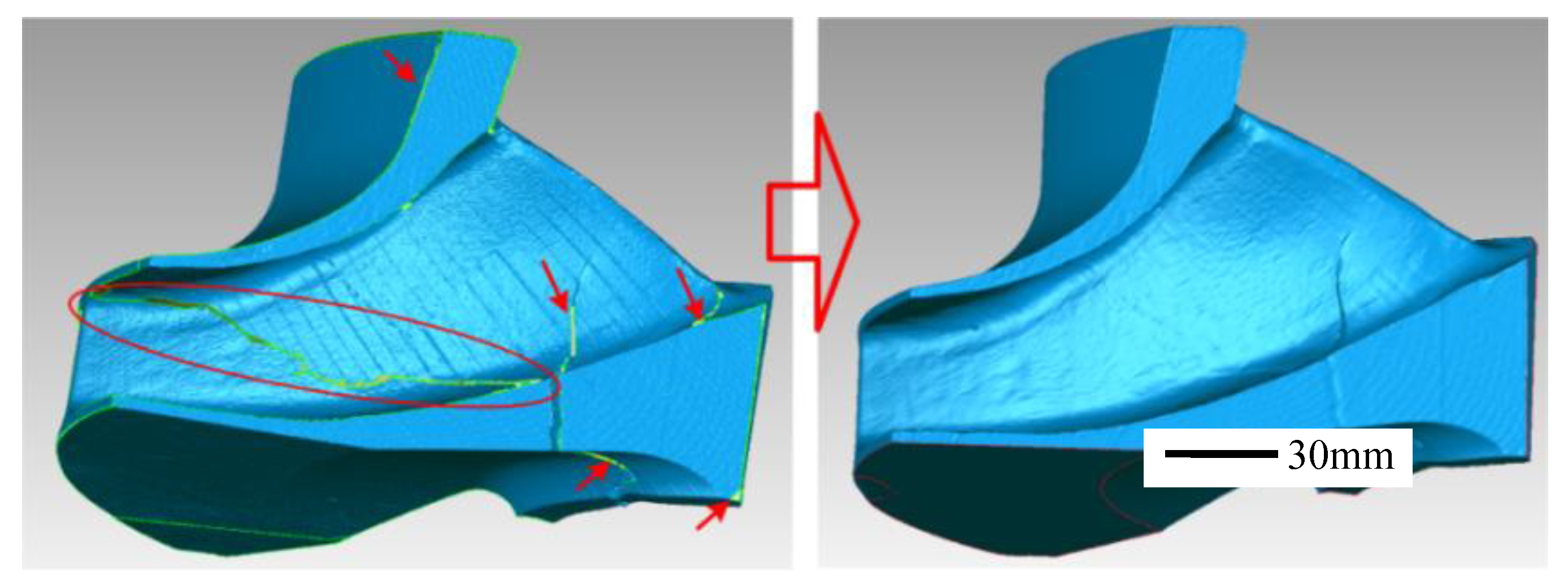
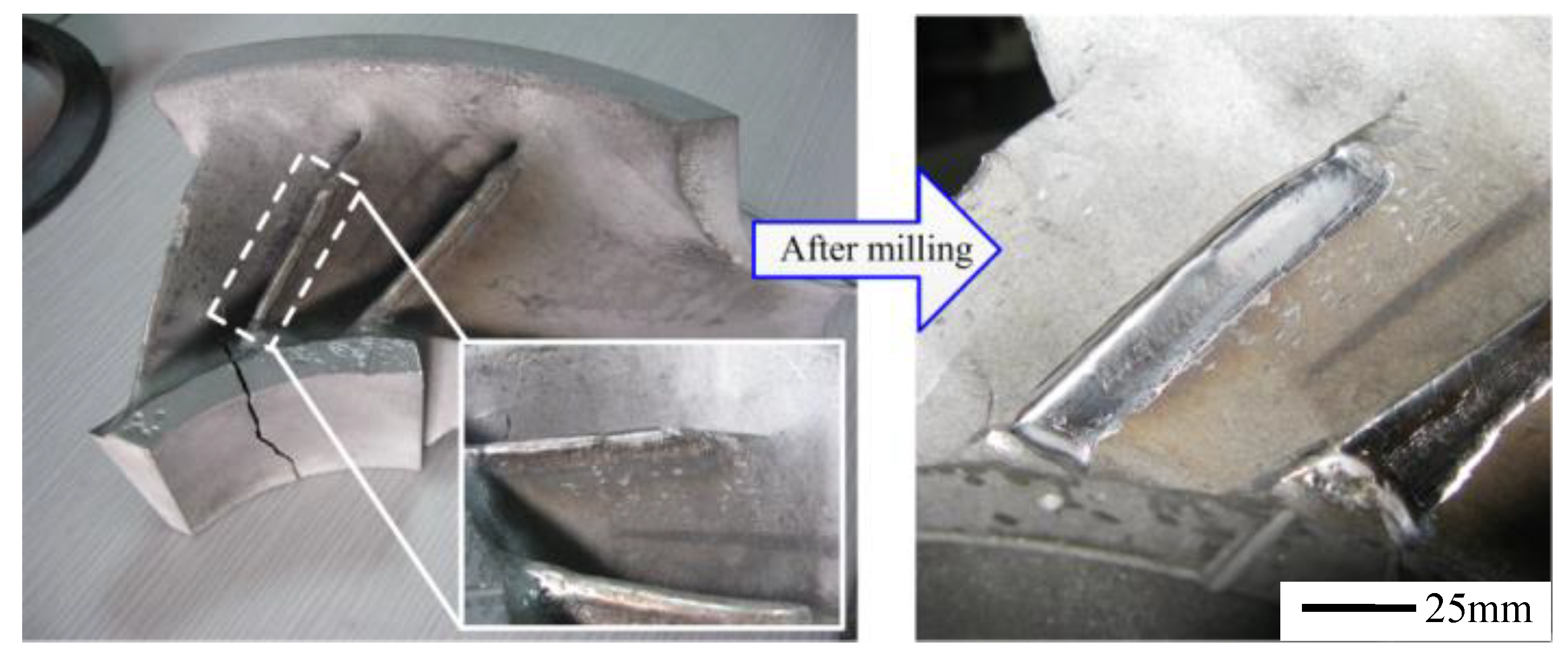
The macroscopic feature of the LAM repair blade before and after milling is shown in
Figure 15. After post inspection, the final geometric tolerance of the remanufactured blade was shown to be within 150 μm, while most of the remanufactured position was within 30 μm of the desired geometry. After an accurate and detailed analysis, the entire process of centrifugal compressor blade remanufacturing was successfully completed.


