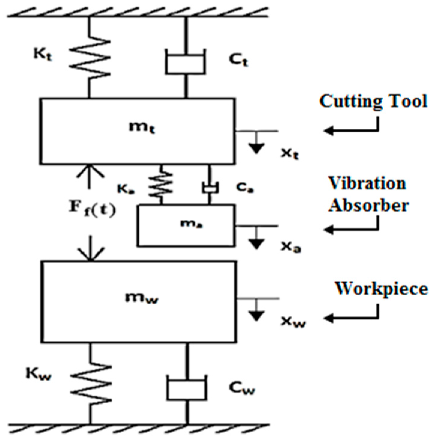
1. Introduction
Smart machining aims to enhance the efficacy, accuracy, and productivity of manufacturing processes by utilizing cutting-edge technologies and data-driven approaches consisting of machine learning (ML), data analytics, automation, the Internet of Things (IoT), and artificial intelligence (AI). To improve industrial competitiveness and propel the expansion of the machining industry, smart machining systems have grown in prominence. To evaluate real-time data and proactively modify the manufacturing process, it uses optimization algorithms and sensor-based control systems. This results in improved quality and shorter production times. In addition, smart machining involves the utilization of intelligent cutting tools that are equipped with sensors and algorithms to maximize the lifespan of the tool, minimize tool deterioration, and improve cutting efficiency. It is also utilized in CNC machining centres to optimize and simulate machining pathways according to real tool trajectories [
1,
2]. The regenerative chatter that occurs between a cutting tool and a workpiece causes an unstable machining process, a poor surface finish, and reduced productivity. Tobias [
3] and Tlusty [
4] carried out numerous studies on regenerative chatter in various machining processes and predicted that machining stability was influenced by the real part of the frequency response function of the machining system. A simplified procedure to construct stability lobes for various machining processes was explained. The chatter stability of the tool–workpiece system has been analyzed by various researchers, and some of the studies conducted in the turning process are described below. Jen et al. [
5] studied machine tool chatter using a dynamic model that consists of the workpiece, the turret, and the lathe bed. The stability of the system was analyzed in the frequency domain. Chen and Tsao [
6] analyzed the machining stability in the turning process by taking the deformation of the workpiece into account. The workpieces were categorized as rigid and flexible. It was concluded that the flexibility of the workpiece affects workpiece deflection and the critical chip width. Vela-Martineza et al. [
7] analyzed chatter in the turning process using a two-DOF model that considers the dynamics of both the workpiece and the cutting tool. The linear stability analysis was carried out in the Laplace domain, and the result showed that the variation in the stiffness and damping ratio of the cutting tool affects the stability limit. Cardi et al. [
8] studied the influence of workpiece dynamics on machine stability in the turning process. A neural network trained with particle swarm optimization was used to find the radial displacement of the workpiece. The authors also investigated the transition process from stable machining to chatter experimentally. Siddhpura et al. [
9] analyzed machining stability of the flexible tool–workpiece system of a turning process. Stability lobes were analytically obtained for cantilever and simply supported end conditions of a flexible workpiece. Lu et al. [
10,
11,
12] analyzed cutting stability during the turning of a slender workpiece and predicted a stable depth of cut for different locations of the workpiece. The effects of support and the flexibility of the workpiece on the turning process were also studied. Furthermore, it was demonstrated that increasing the workpiece’s flexibility and damping can increase the stable depth of cut. To assess the dynamic response of a machining system and its stability, Abainia et al. [
13] estimated cutting tool displacement analytically and numerically. Chatter in machining processes can be controlled by various passive and active vibration control techniques.
Passive vibration control techniques using vibration absorbers are still considered an effective way of controlling chatter, as the design and implementation of such techniques are quite simple. Rivin et al. [
14] suggested a method to enhance the dynamic stability of the boring bar using a TMD. The optimal tuning ratio and damping ratio of the TMD were found using the Routh–Hurwitz stability criterion by considering a two-DOF lumped-parameter model. Tarng et al. [
15] used a piezoelectric inertia actuator as a TMD and showed that the attachment of a TMD can reduce the magnitude of the FRF of the cutting tool in turning operations. Duncan et al. [
16] studied the dynamic absorber effect in high-speed machining to improve machining stability. Receptance coupling substructure analysis was applied to predict this effect. Sims and Yang et al. [
17,
18] proposed a new tuning methodology to design a vibration absorber to control chatter. This tuning methodology was based on maximization of the negative real part of the FRF. The author also carried out a time-domain simulation of a milling process to prove the effectiveness of the absorber. Miguelez et al. [
19] analyzed the chatter stability of a boring bar with a TMD attachment. Min–max optimization was used to find the optimum tuning parameters for the TMD. Rubio et al. [
20] found optimum tuning parameters and the position of the tuned mass damper in a boring process using the Nelder–Mead method. The boring bar and TMD were considered as continuous and lumped parameter systems, respectively. Stability lobes were plotted to prove the effectiveness of the TMD and the method adopted. Kucuk and Korkut [
21] investigated the effect of cutting vibrations on bored hole quality by optimizing conicity and circularity using the experimental design method. Van Zyl et al. [
22] incorporated an adaptive dynamic vibration absorber that was claimed to be effective at different boring bar and spindle lengths, and optimal tuning was obtained by minimizing the negative real part of FRF. The soft computing techniques were explored for machinability and chatter stability in machining processes for implementation of smart manufacturing systems [
23,
24,
25,
26,
27,
28]. In addition, Korkmaz et al. [
29] presented a comprehensive review of analytical modelling methods in machining processes, focusing on cutting forces, temperatures, tool wear, surface roughness, chip morphology, and vibration.
The study discussed the applicability, advantages, and limitations of analytical models compared with numerical and AI-based approaches, highlighting their suitability for real-time process monitoring and Industry 4.0 applications. Saravanamurugan et al. [
30] analyzed the reliability of a tool–workpiece system due to the presence of uncertainty in system parameters and predicted reliable stability lobes. Wang et al. [
31] explored a two-degree-of-freedom TMD to control chatter in the end milling process, and the end mill was treated as a continuous system. He et al. [
32] developed a TMD with an internal collision mechanism to dissipate energy during the end milling process. Yu et al. [
33] developed an adaptive vibration absorber by using a distributed mass system and applied the absorber system in the gear hobbing process. Fadlalla et al. [
34] employed a genetic algorithm and particle swarm optimization to optimize the absorber tuning ratio and damping ratio, and the results showed an increase in critical depth of cut compared with conventional tuning methodologies. Dogan et al. [
35] developed multiple tuned mass dampers for milling cutters to control chatter arising due to rotating effects. The literature review on tuned mass dampers for chatter control revealed that most existing studies either assume a rigid workpiece or neglect the coupled dynamics between the cutting tool and the workpiece. Consequently, the influence of workpiece flexibility on optimal TMD tuning remains insufficiently addressed, particularly in boring and deep-hole machining operations where workpiece dynamics can vary significantly. This limitation restricts the applicability of conventional tuning approaches, such as equal-trough methods, under realistic machining conditions. To address this gap, this paper develops a linear stability analysis of a three-DOF tool–workpiece–TMD system and proposes an optimization-based tuning strategy that explicitly accounts for workpiece dynamics. The optimal TMD parameters are determined by three representative categories of workpieces: rigid workpieces, workpieces with dynamic characteristics comparable to the tool, and flexible workpieces. Specifically, the main contribution of this work is to develop a three-degree-of-freedom analytical stability model incorporating tool, workpiece, and TMD dynamics. This paper also aims to systematically demonstrate the limitations of conventional TMD tuning methods under varying workpiece dynamic conditions. Moreover, an optimization-based strategy to obtain robust TMD parameters that yield equal stability lobe troughs is proposed. Furthermore, the proposed approach is validated using an additively manufactured tuned mass damper.
3. Stability Analysis
The stability analysis aims to determine the critical depth of cut as a function of spindle speed and to evaluate how TMD tuning parameters influence the shape and robustness of stability lobes under varying workpiece dynamics. In this paper, the stability of the dynamical system is analyzed using the Laplace transform in the frequency domain. Taking the Laplace transform of Equation (3) and assuming the zero initial condition, we get:
where
is the transfer function matrix.
Equation (4) can be rewritten as follows, which can be reduced to:
In the Laplace domain, the dynamic feed force vector
can be expanded as follows:
where the uncut chip thickness vector is
and the dynamic chip thickness matrix is
.
Substitution of Equation (5) in Equation (6) yields:
By expanding the denominator term of Equation (7), the characteristic equation of the dynamic system is obtained as follows (Equation (8)):
where
denotes the response at coordinate
i due to a unit force applied at coordinate
j. Each element
represents the displacement response at the
ith coordinate due to a unit force applied at the
jth coordinate.
Equation (8) can be solved to find its roots, which represent the poles of the dynamic system. The location of the poles in the complex plane provides information on system stability. In order to execute the stability analysis, the condition of the critical stability
is substituted in Equation (8) and the resulting real and imaginary parts are segregated. From the real and imaginary parts, the expression for the critical depth of cut and the phase angle of the transfer function for the stable machining process are obtained as:
where
etc. are the real parts of and , etc. are the imaginary parts of , where ,, , , , , , , , and .
By rewriting Equation (10) in the following manner, the phase angle of the transfer function can be related to the spindle speed:
Equation (11) can be reduced as:
As a result, for one cycle of the machining process, the phase angle of the transfer function can be related to the chatter frequency
and time period
using the following relationship:
In the turning and boring processes, the spindle speed is
. Substituting this relation into Equation (13), the detailed expression for the spindle speed is obtained:
where the
is referred to as the lobe number.
Having completed the stability analysis, the stability lobes are plotted as shown in the
Section 3 and
Section 5. These are constructed to visualize the effect of TMD on the machining stability of the tool–workpiece system. The optimum TMD parameters obtained using the two-degree-of-freedom methodology [
17], as presented in
Table 1, are used in this study.
The tool dynamics listed in
Table 2 define the reference configuration used for the theoretical parametric investigation. This reference tool is retained throughout the analytical stability analysis so that the influence of varying workpiece dynamic characteristics can be examined systematically while keeping the tool dynamics fixed. In order to construct stability lobes, the two optimum tuning parameters, namely frequency ratio and damping ratio for the corresponding mass ratio of the TMD, are required. The frequency ratio is the ratio between the natural frequency of the TMD and the tool, the damping ratio is the ratio between the damping coefficient and critical damping coefficient of the TMD, and the mass ratio is the ratio between the mass of the TMD and the tool. These parameters have been found by researchers so far with the assumption that either the workpiece or the tool is a rigid body [
17,
18,
19]. Sims and Yang et al. [
17,
18] adopted an equal trough tuning method for a two-degree-of-freedom model by optimizing the real part of the frequency response function (FRF) of either the tool or the workpiece for the design of a TMD. But this assumption may not work universally because the workpiece and the tool may exhibit flexibility based on variations in geometric and material properties. To check the suitability of the two-degree-of-freedom methodology [
17,
18] for the three-DOF models, stability lobes are constructed for this model using the corresponding TMD tuning parameters.
Table 1.
Optimum parameters of TMD selected with two-degree-of-freedom methodology [
17] for the construction of stability lobes.
Table 1.
Optimum parameters of TMD selected with two-degree-of-freedom methodology [
17] for the construction of stability lobes.
| Mass Ratio (μ) | Workpiece Damping (ξw) | Frequency Ratio | Damping Ratio (ξa) |
|---|
| 0.01 | 0.0347 | 1.0543 | 0.06572 |
| 0.05 | 0.0347 | 1.0592 | 0.1386 |
The dimensions of workpieces with fixed-free end conditions are assumed, and their dynamic characteristics are shown in
Table 2 for the construction of stability lobes. These values are considered based on the following three classifications:
Condition (i): tool–rigid workpiece system stiffness of the workpiece is far greater than that of the tool.
Condition (ii): tool–workpiece system with similar dynamics and nearly equal stiffness of the tool and the workpiece.
Condition (iii): tool–flexible workpiece system stiffness of the tool is much lower compared to that of the tool.
Table 2.
Dynamic characteristics of tool and workpieces.
Table 2.
Dynamic characteristics of tool and workpieces.
| | Parameters and Dynamic Characteristics |
|---|
| Tool-shank (Mild Steel) | Mass m (kg) | 0.1725 |
| Feed Force Coefficient Kf (N/m2) [7] | 684 × 106 |
| Density ρ (kg/m3) | 7850 |
| Diameter D (m) | 25 × 10−3 |
| Length L (m) | 19 × 10−2 |
| Natural Frequency f (Hz) | 541.73 |
| Damping Ratio ξ | 0.0347 |
Workpiece
(Mild steel) | | Condition 1 | Condition 2 | Condition 3 |
| Mass m (kg) | 0.4937 | 0.1739 | 0.1634 |
| Density ρ (kg/m3) | 7850 | 7850 | 7850 |
| Young’s Modulus E (N/m2) | 190 × 109 | 190 × 109 | 190 × 109 |
| Outer Diameter Do (m) | 70 × 10−3 | 44 × 10−3 | 47 × 10−3 |
| Inner Diameter Di (m) | 40 × 10−3 | 39 × 10−3 | 44 × 10−3 |
| Length L (m) | 0.1 | 0.28 | 0.4 |
| Natural Frequency f (Hz) | 5548.94 | 516.15 | 276.94 |
| Damping Ratio ξ | 0.0347, 0.05 | 0.0347, 0.05 | 0.0347, 0.05 |
By considering three different sizes of hollow pipes made of steel, as provided in
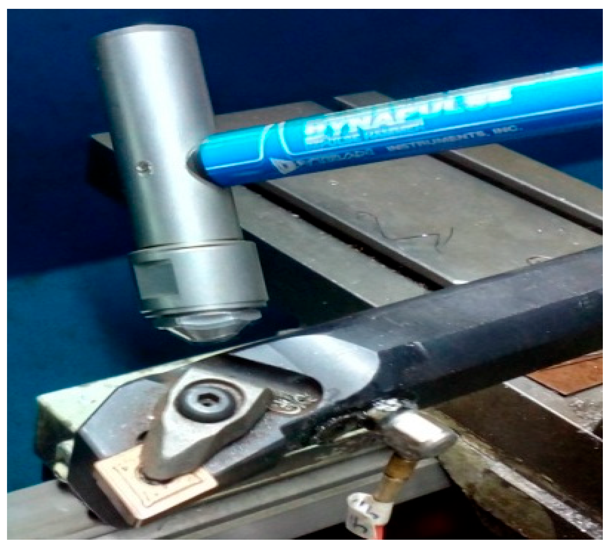
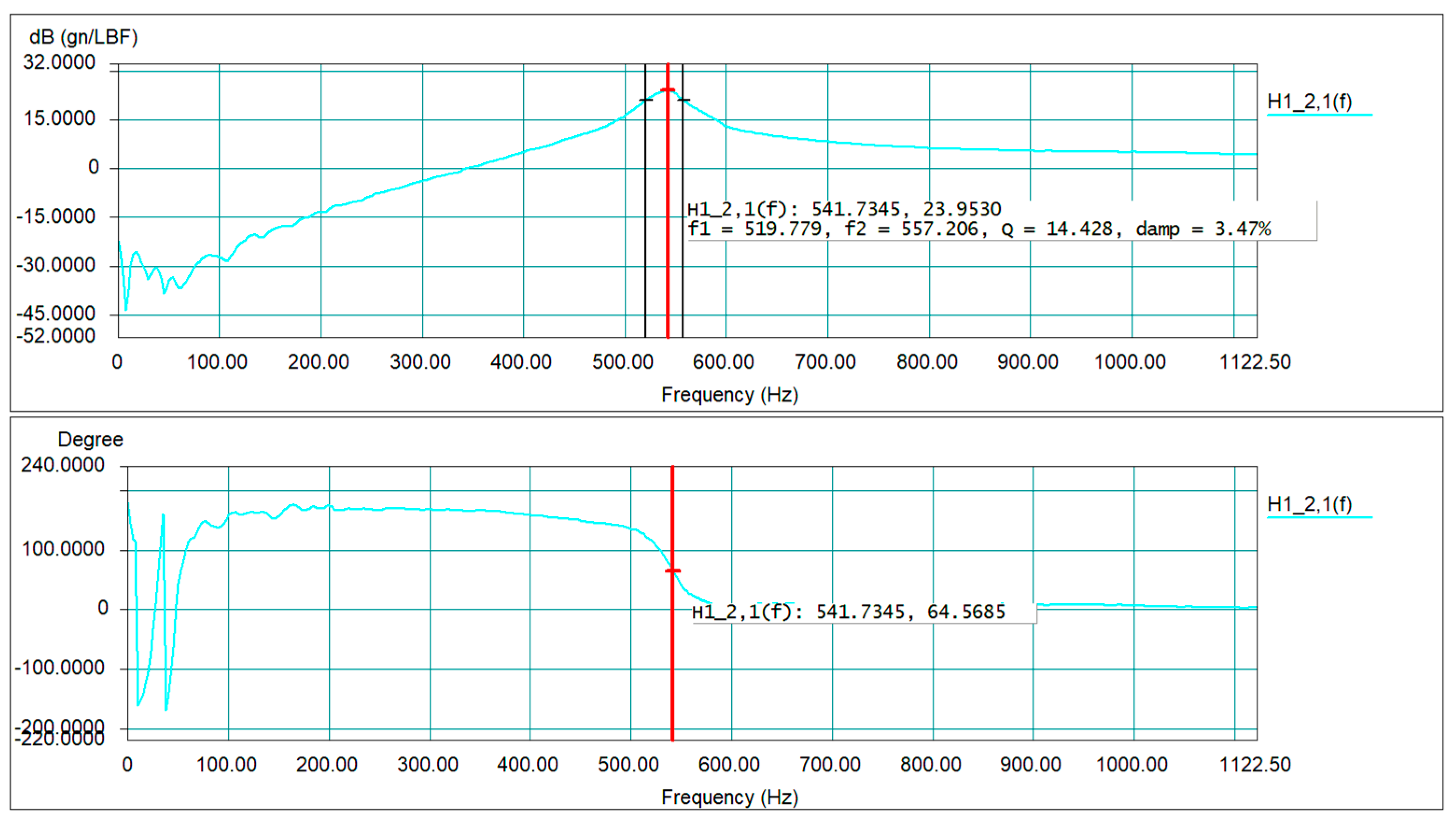
Table 2, the three different cases of the tool–workpiece system have been established theoretically. The dynamic characteristics of the cutting tool were obtained using the impact hammer test. The experimental setup and the acquired FRF are shown in
Figure 2 and
Figure 3, respectively. For the workpiece, standard analytical expressions of equivalent mass and stiffness of the fundamental mode of a fixed-free beam suggested by Rao [
36] were used.
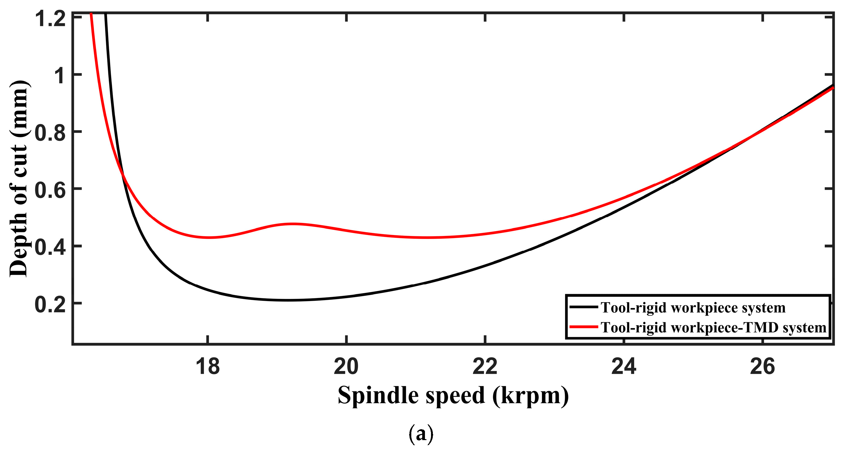
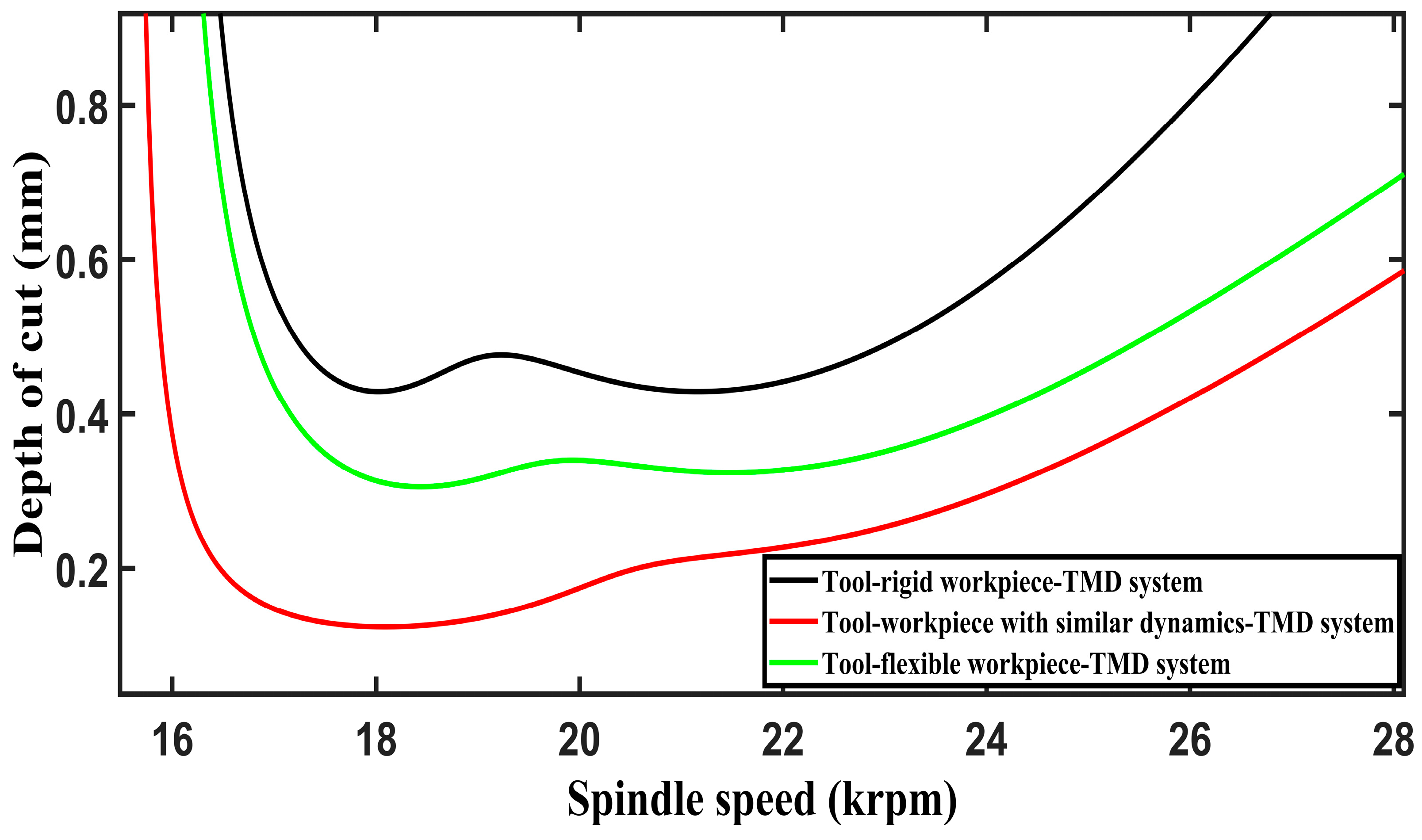
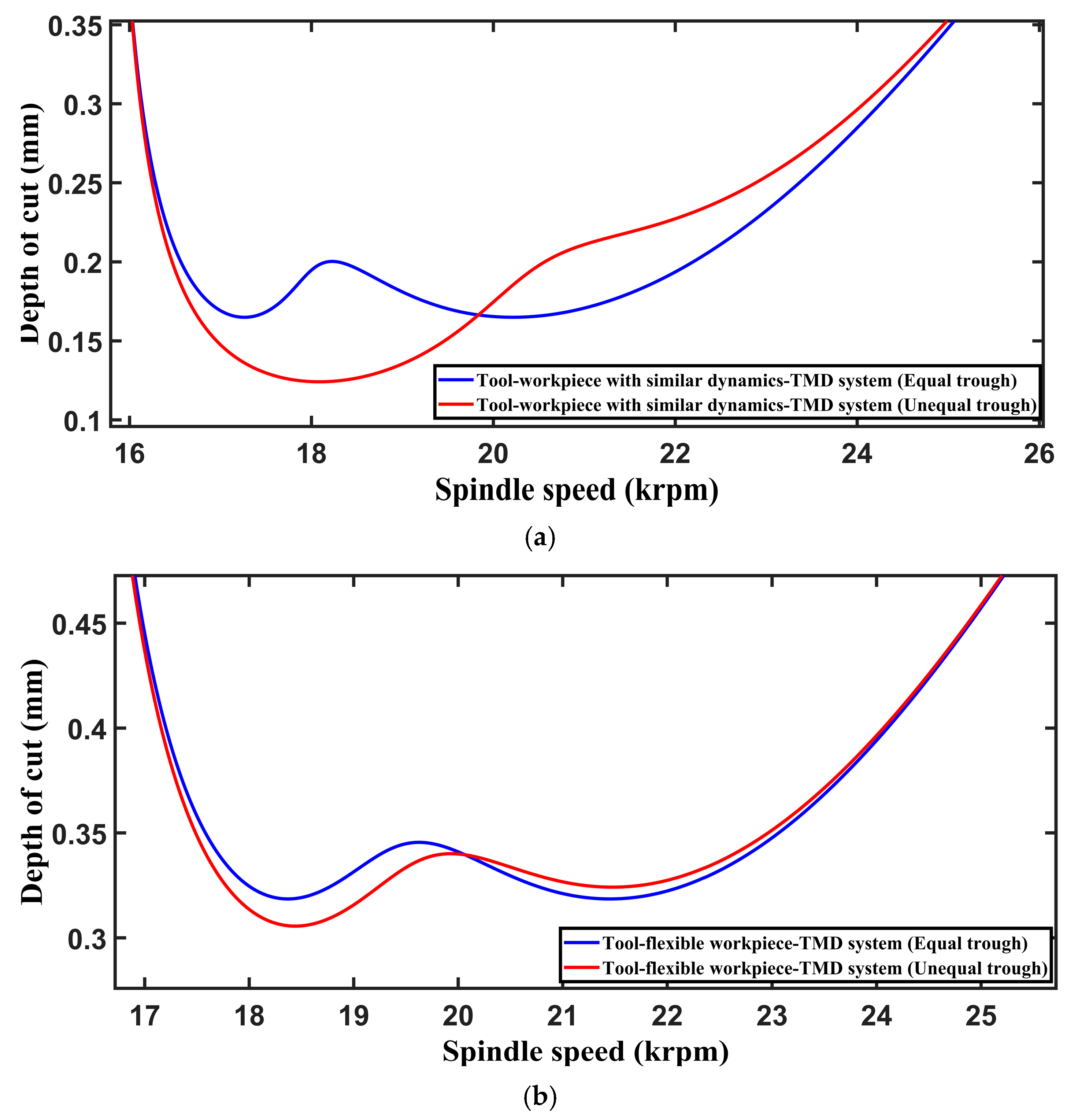
The stability lobes are constructed for the three cases of the tool–workpiece system, as shown in
Figure 4, using the algorithm adopted by Altintas [
37]. From the above stability lobes, it is observed that the tool–rigid workpiece–TMD system shows equal troughs. The equal troughs are obtained because the stiffness of the workpiece is far greater than that of the tool, thus making it a 2DOF system. However, in conditions (ii) and (iii), the equal troughs are affected, i.e., the tool–workpiece system with similar dynamics and the tool–flexible workpiece system, respectively. This confirms the hypothesis that workpiece dynamics influence the determination of optimum parameters of the TMD. When workpiece dynamics are included, the TMD–tool system no longer behaves as an isolated primary structure. The workpiece introduces additional flexibility, modal interaction, and phase changes in the regenerative transfer function. As a result, the originally balanced absorber effect can be distorted, and the troughs of the stability lobes become unequal. This means that the TMD no longer provides a uniform stabilizing influence over the operating range. Some speed regions may show substantial improvement, while others remain weak due to adverse tool–workpiece dynamic coupling. This distortion directly affects the improved stability lobe in the presence of the TMD. Although the overall envelope may still rise relative to the uncontrolled case, the improvement becomes non-uniform. The practical consequence is that the apparent enhancement in chatter resistance may be misleading if judged only by peak lobe elevation. The real benefit of the absorber should be assessed by how effectively it lifts and regularizes the troughs, because those troughs determine the minimum guaranteed stable cutting limit. If workpiece dynamics depress one or more troughs, the machining system remains vulnerable at those spindle speeds, even with the TMD.
Figure 2.
Experimental setup.
Figure 2.
Experimental setup.
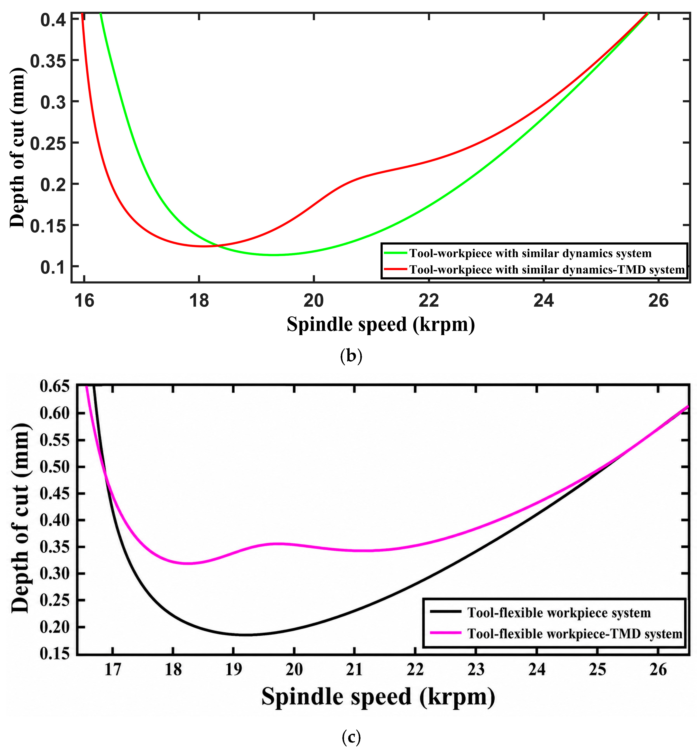
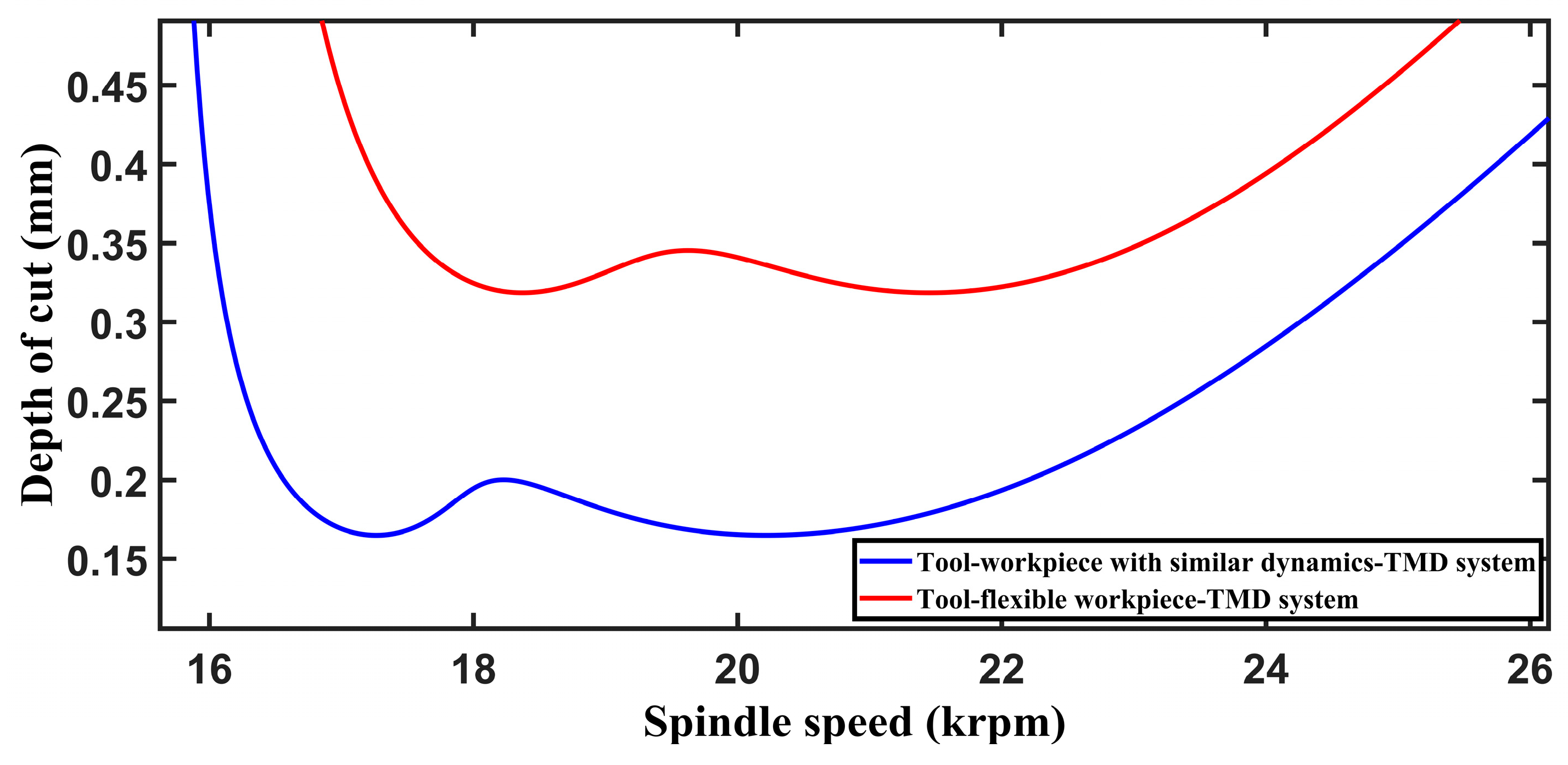
Hence, further modification of the optimum TMD parameters is needed to have equal troughs. However, the stability limit is improved significantly with the addition of TMD that is designed. This can be inferred from the stability lobes shown in
Figure 5 for all three cases of tool–workpiece systems with and without TMD. The lobes for the tool–workpiece system are plotted using equations developed by Vela-Martinez [
5].
Figure 3.
Frequency response function (FRF) of the tool.
Figure 3.
Frequency response function (FRF) of the tool.
Figure 4.
Stability lobes of tool–workpiece system with TMD designed based on two-degree-of-freedom approach [
17,
18].
Figure 4.
Stability lobes of tool–workpiece system with TMD designed based on two-degree-of-freedom approach [
17,
18].
Figure 5.
(a) Stability lobes of tool–workpiece system with and without TMD. (b) Tool–workpiece with similar dynamics. (c) Tool–flexible workpiece system.
Figure 5.
(a) Stability lobes of tool–workpiece system with and without TMD. (b) Tool–workpiece with similar dynamics. (c) Tool–flexible workpiece system.
4. Optimization of TMD for Tool–Workpiece System
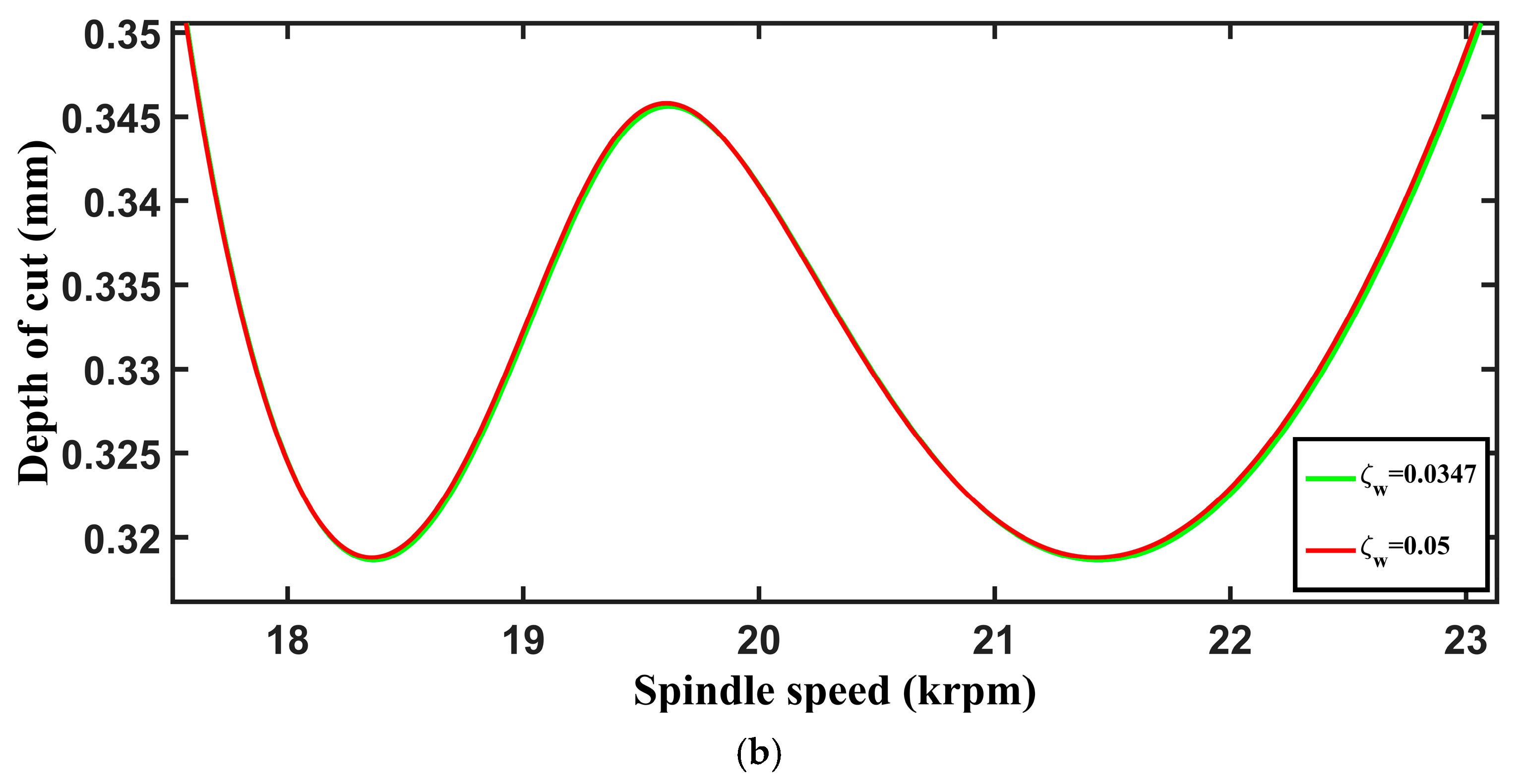
The optimization of the TMD is carried out with the intention of getting equal troughs of stability lobes for varying conditions of workpiece dynamics. This may improve the efficiency of the TMD further. Moreover, lobes with equal troughs may be easily adopted during the machining process. The objective is to maximize the minimum value of the depth of cut. By maximizing the minimum critical depth of cut, the proposed optimization ensures that the absorber tuning is governed by the weakest stability condition, resulting in robust chatter suppression across a wide range of operating conditions. The two parameters of the TMD that must be optimized are the natural frequency (ωa) and damping ratio (ξa). Therefore, the objective function of the optimization problem can be expressed as max–min (bc) subject to constraints ωa min < ωa < ωa max and ζa min < ζa < ζa max. For each candidate combination of wa and ξa, the characteristic equations were evaluated over the selected chatter frequency interval [ωmin, ωmax] using a frequency increment of Δω. We obtained the positive critical depth-of-cut values over this frequency range and identified the minimum. The optimization objective was formulated to maximize this minimum critical depth of cut, ensuring that the weakest stability condition governs TMD tuning and promoting the equal-trough condition of the stability boundary. The optimization procedure needs to search for the optimum natural frequency and damping ratio of the TMD by maximizing the minimum critical depth of cut.
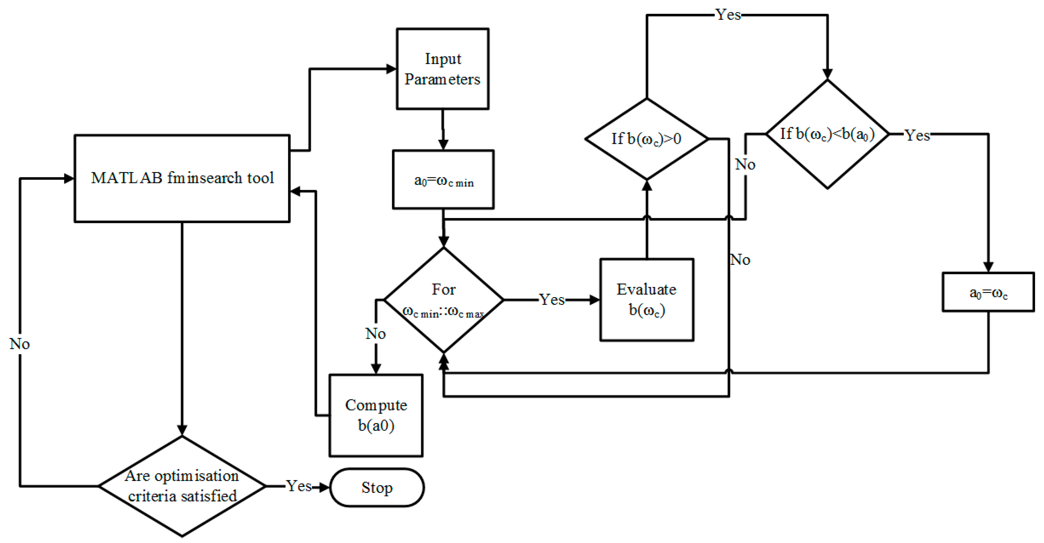
The optimization procedure is implemented as an iterative numerical algorithm consistent with the flowchart shown in
Figure 6. Initially, the absorber parameters m
a, k
a, and c
a are assigned starting values within the prescribed bounds. The chatter frequency range [ω
min, ω
max] is then defined based on the dominant structural dynamics of the system and discretized into a sufficiently fine set of frequency points to ensure accurate capture of stability variations. For a given set of absorber parameters, the limiting depth of cut b(ω) is evaluated at each discrete frequency using the derived stability formulation, which involves computation of the dynamic stiffness matrix, its inversion to obtain the transfer function matrix, and extraction of the relevant real part of the relative receptance. The minimum value of b(ω) over the entire frequency range is then identified, representing the critical stability limit (trough). This minimum value serves as the objective function for the optimization. The absorber parameters are subsequently updated using the MATLAB R2023b fminsearch algorithm [
38], which iteratively modifies the design variables to maximize the minimum stability level. After each update, convergence is assessed against prescribed tolerances for changes in the objective function and the design variables. If the convergence criteria are not satisfied, the procedure is repeated with the updated parameters. Upon convergence, the optimal set of absorber parameters corresponding to the critical stability limit is obtained, thereby ensuring improved and uniform chatter resistance across the operating range. This optimization strategy ensures that the weakest stability limit governs the tuning process, resulting in TMD parameters that remain effective over a wide range of operating conditions. Because the max–min objective is non-convex and fminsearch is a local Nelder–Mead optimiser, we used a multi-start strategy to reduce sensitivity to the initial design point. The optimization was repeated from multiple combinations of frequency ratio and absorber damping ratio distributed within the prescribed bounds. The converged candidates were compared based on the maximum value of the minimum critical depth of cut, and only physically admissible solutions with positive damping ratio were retained. We further verified the final optimum by examining the resulting stability curve for the equal-trough condition.
The optimized absorber’s natural frequency can be expressed in terms of the frequency ratio, which is the ratio between the natural frequency of the absorber and the tool.
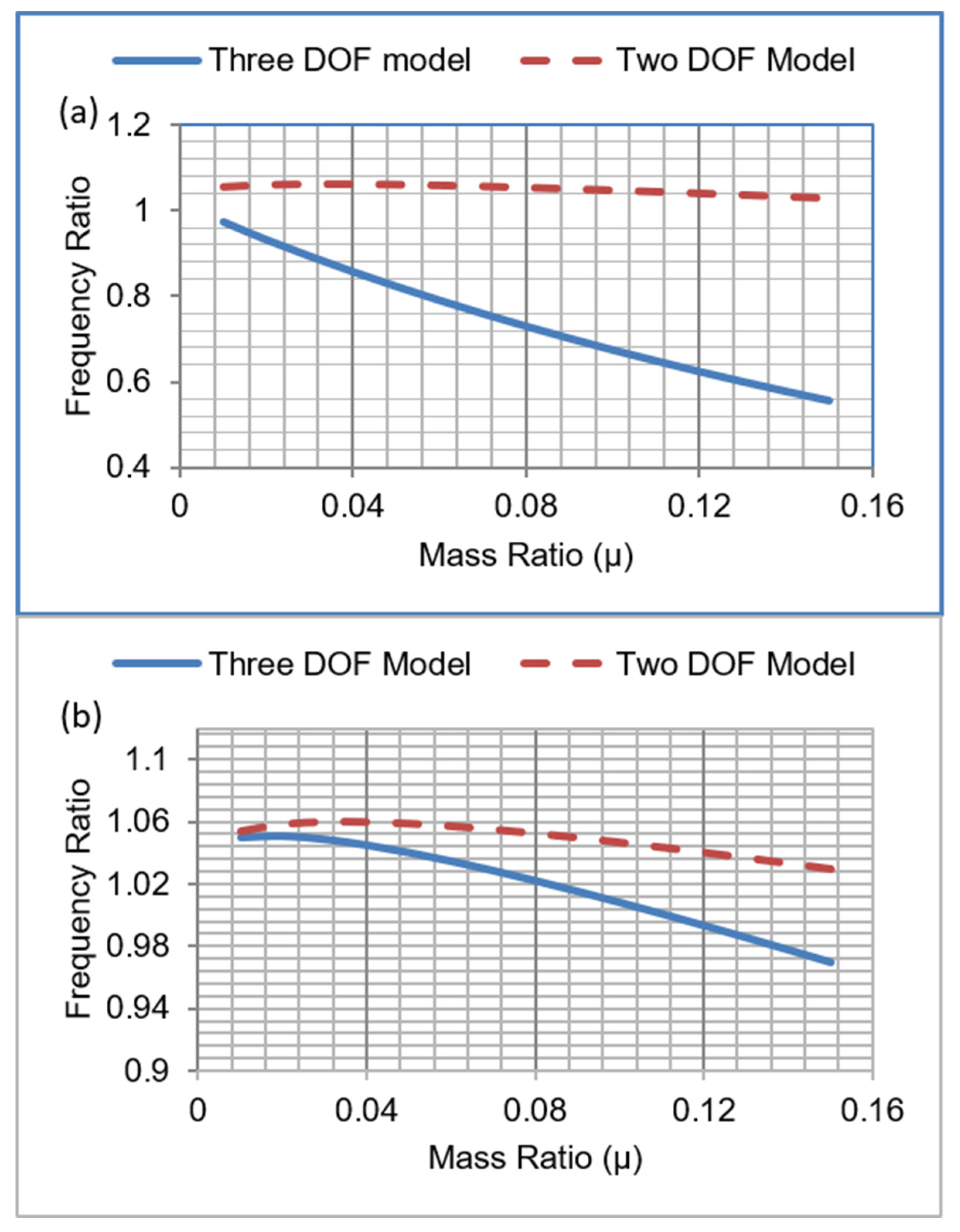
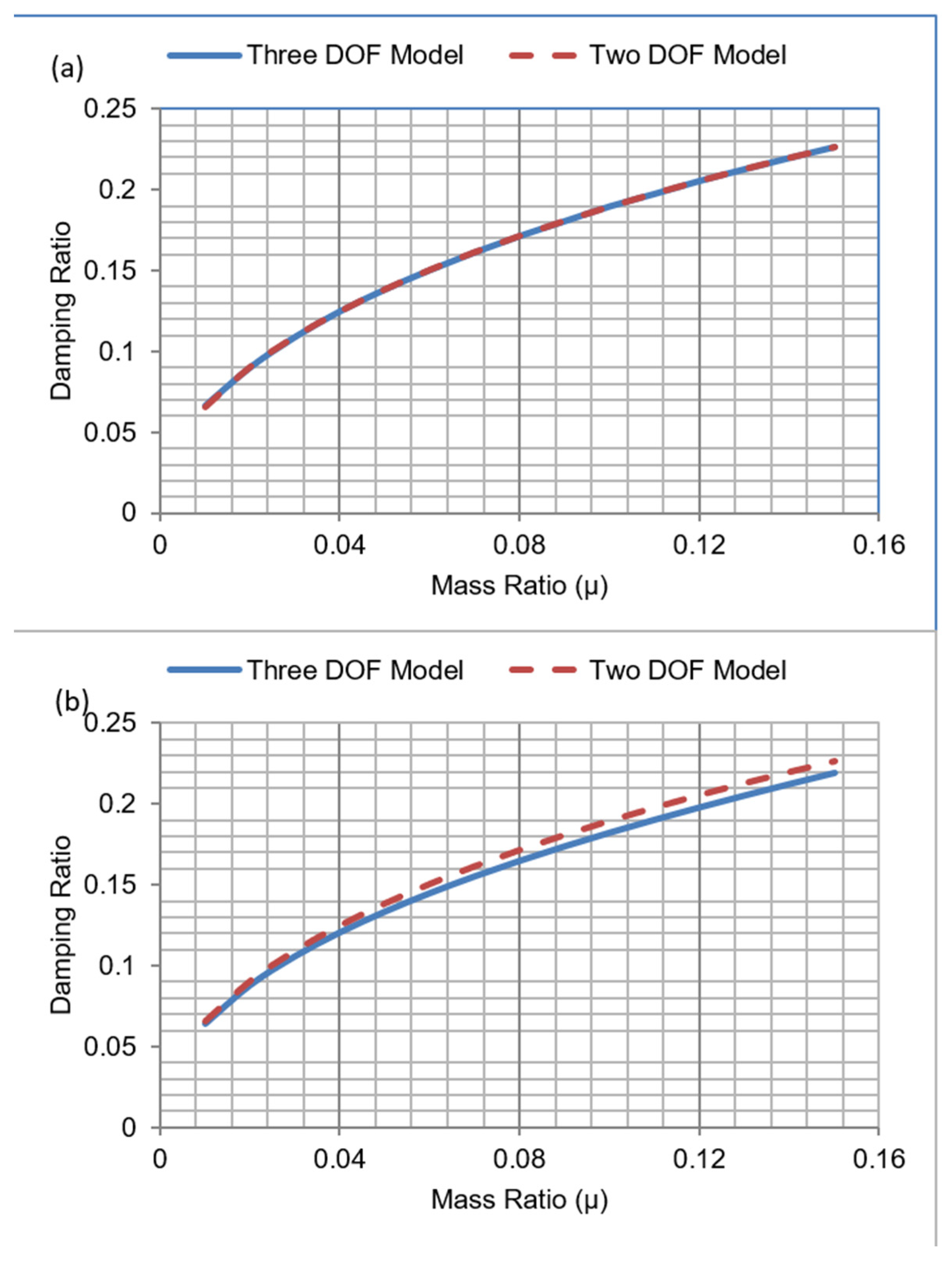
Figure 7 and
Figure 8 show the difference between the optimum TMD parameters obtained using the two-DOF approach [
17] and the proposed approach.
From
Figure 7, it can be observed that the values of the optimum frequency ratio obtained based on the two-DOF approach [
17] are greater than unity up to a mass ratio of 0.15, but for a tool–workpiece with similar dynamics–TMD system, the values of modified frequency ratios are less than unity for the complete range of mass ratio. As far as the tool–flexible workpiece–TMD system is concerned, the values of modified frequency ratios become less than unity only beyond the mass ratio of 0.12. It may be observed from
Figure 7 that there is a considerable difference between the frequency ratio obtained through the two-degree-of-freedom methodology [
17,
18] and the proposed approaches, whereas there is no significant difference in the values of damping ratios, as seen in
Figure 8. It can be reiterated here that two-DOF approaches and the proposed approaches use a two-degree-of-freedom model (two-DOF model) and a three-degree-of-freedom model (three-DOF model), respectively.
6. Experimental Validation
This section aims to validate the effectiveness of the optimized tuned mass damper parameters predicted by the proposed analytical model. The boring bar employed in the experimental proof-of-concept study differs from the reference tool used in the theoretical parametric analysis. The experimental bar had a diameter of 32 mm and a measured fundamental natural frequency of approximately 820 Hz. The experiment aimed to verify the structural dynamic effect of TMD attachment rather than directly reproduce the stability lobes calculated for the 541.73 Hz reference tool. Accordingly, the max–min optimization was repeated using the dynamic characteristics of the 820 Hz boring bar, and the corresponding optimum TMD parameters are reported in
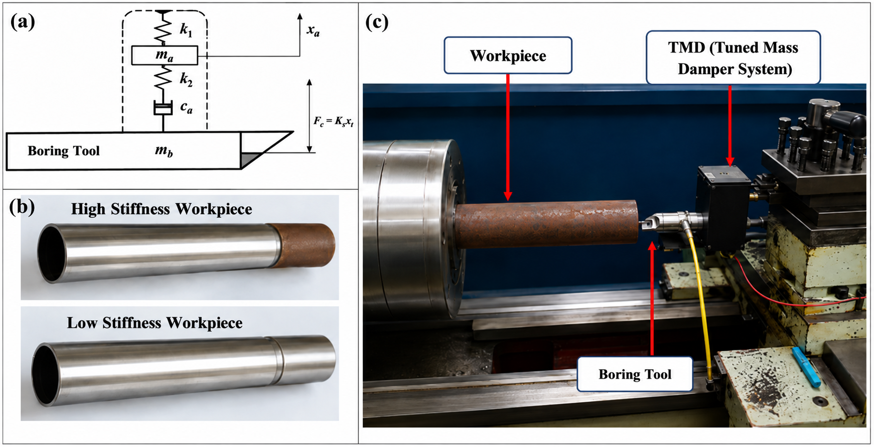
Table 4. The tuned mass damper is developed as an assembly of an additively manufactured casing, a spring, and a mass system. The absorber system is attached to the boring bar to complete the setup. The absorber assembly with the boring tool and the machining setup are shown in
Figure 12. The absorber casing was additively manufactured using the fused deposition modelling process with polylactic acid (PLA), which has moderate vibration-absorption capabilities. The PLA-based TMD used in this study was developed as a proof-of-concept prototype to investigate the structural dynamic interaction between the absorber and the tool–workpiece system. The experiments were relatively short; therefore, they did not evaluate long-term changes in absorber stiffness and damping caused by thermal exposure, viscoelastic relaxation, and cyclic loading. Because these parameter variations can lead to TMD detuning, characterization of ka and ζa as functions of temperature and accumulated loading cycles is required before the proposed PLA configuration can be considered for prolonged industrial machining applications. With the absorber attached and tested with the boring bar (fundamental natural frequency of 820 Hz), the optimum absorber parameters were obtained by rerunning the min–max optimization procedure, and the results are provided in
Table 4.
Figure 12.
(a) TMD assembly with a boring bar. (b) Workpieces with different stiffnesses. (c) Machining setup.
Figure 12.
(a) TMD assembly with a boring bar. (b) Workpieces with different stiffnesses. (c) Machining setup.
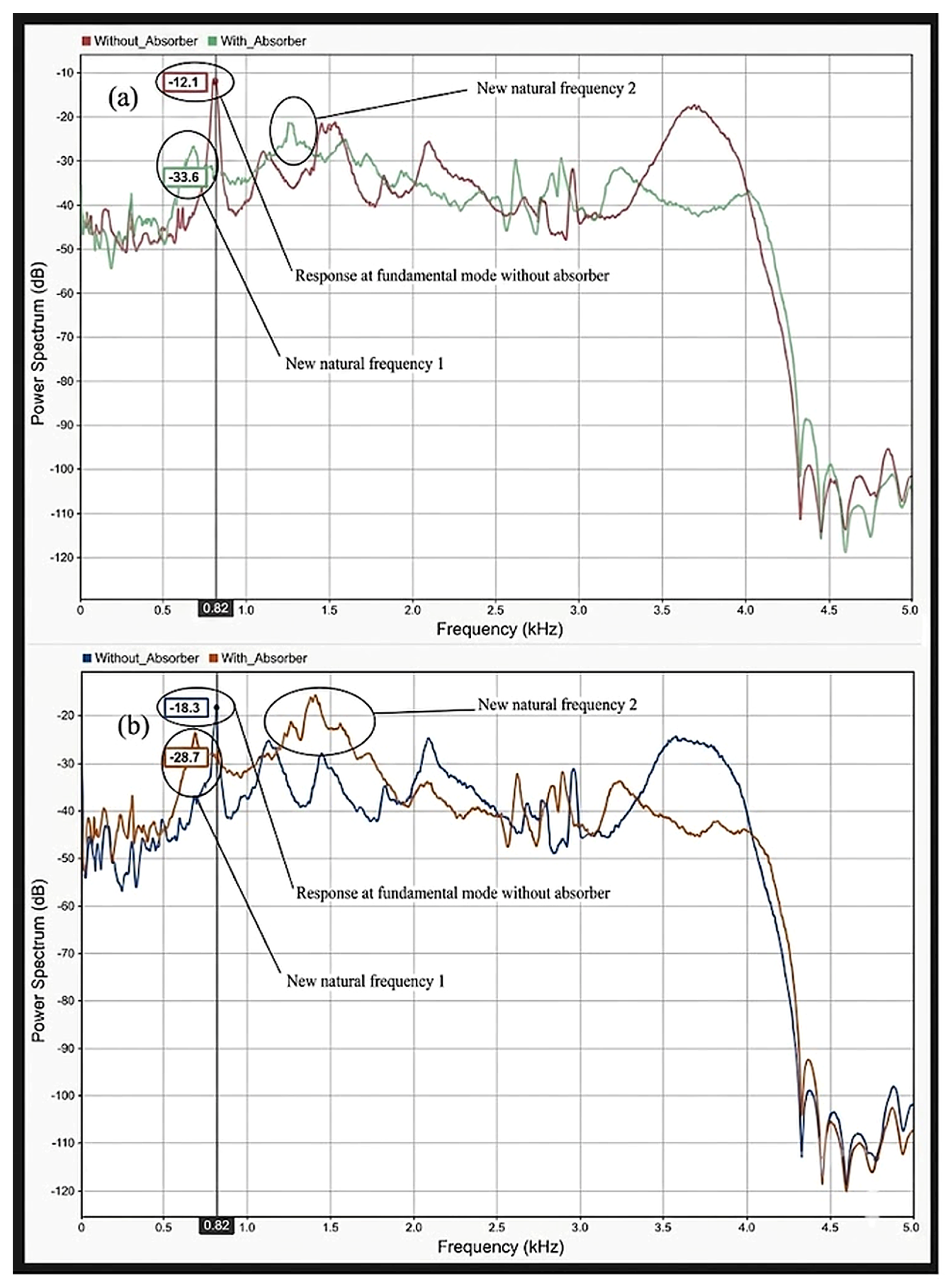
The vibration absorber at a tuning ratio of 0.6 was placed 80 mm from the tip on the 32 mm boring bar, and the accelerometer sensor was placed near the tip of the boring tool. Kisteler DAQ was used to capture the vibration data in the time domain. The experimental results were analyzed by capturing the power spectrum, shown in
Figure 13, from the time-domain vibration signals of machining with and without an absorber. The objective of implementing a tuned mass damper for the boring tool is to reduce the chatter frequency peak. The experiments in this study were proof-of-concept investigations to verify the structural dynamic effect of the TMD on the tool–workpiece system. We tested each configuration once and did not perform independent replicate experiments. Consequently, we did not apply statistical measures of experimental dispersion or inferential statistical analyses to the present dataset. The measured responses are therefore interpreted qualitatively and comparatively in terms of resonance modification and vibration attenuation rather than as statistically validated machining-performance data. The frequency response functions show that, prior to TMD attachment, the system exhibits a dominant fundamental mode around 820 Hz for both stiffness conditions. The two new peaks occur to the left and right of the natural frequency peaks of the boring tool at 700 Hz and 1300 Hz, indicating the TMD’s influence in controlling the vibrations. Upon integration of the TMD, this single resonance splits into two distinct peaks, indicating effective mode coupling between the primary system and the TMD. Though the difference in the split in the frequency is very marginal, a noticeable reduction in peak amplitude from approximately −12.1 dB to −33.6 dB in the low-stiffness case, and from −18.3 dB to −28.7 dB in the high-stiffness case, confirms that significant attenuation of chatter-prone modes is observed, demonstrating a stronger dynamic influence of the TMD. The observed mode splitting and attenuation of the dominant vibration peak are characteristic signatures of effective tuned mass damper action and are consistent with analytical predictions. This mode splitting is consistently observed across both workpiece conditions, indicating that the TMD effectively modifies the dynamic response irrespective of stiffness variation.
The baseline natural frequency is found to shift with workpiece stiffness, confirming the system’s coupled nature, while the TMD redistributes the dynamic response across two modes, thereby reducing resonance amplification. This behaviour is in direct agreement with the theoretical model, wherein the TMD alters the system transfer function and leads to a redistribution of energy across frequencies, which is the fundamental mechanism for chatter suppression. It is emphasized that the present experiments are intended as a proof-of-concept validation of the dynamic modification introduced by the TMD, rather than a full statistical validation of stability lobes. Future experimental validation will incorporate repeated trials for each configuration to quantify measurement variability and uncertainty and to enable statistical evaluation of the observed differences.
7. Conclusions and Future Directions
This study proposed a novel three-degree-of-freedom analytical framework for designing a tuned mass damper (TMD) for regenerative chatter suppression by explicitly incorporating the coupled dynamics of the cutting tool, workpiece, and TMD. Unlike conventional TMD design approaches that assume a rigid workpiece, the proposed methodology accounts for variations in workpiece stiffness and damping, enabling the development of a more robust chatter-control strategy for intelligent machining systems.
The results demonstrate that the effectiveness of a tool-mounted TMD is strongly dependent on the dynamic characteristics of the workpiece. Although the TMD improves machining stability under all investigated conditions, the greatest increase in stability limit is obtained when the workpiece behaves as a rigid body. The improvement decreases considerably when the tool and workpiece possess comparable dynamic characteristics or when the workpiece is significantly more compliant than the cutting tool, highlighting the importance of considering workpiece dynamics during TMD design.
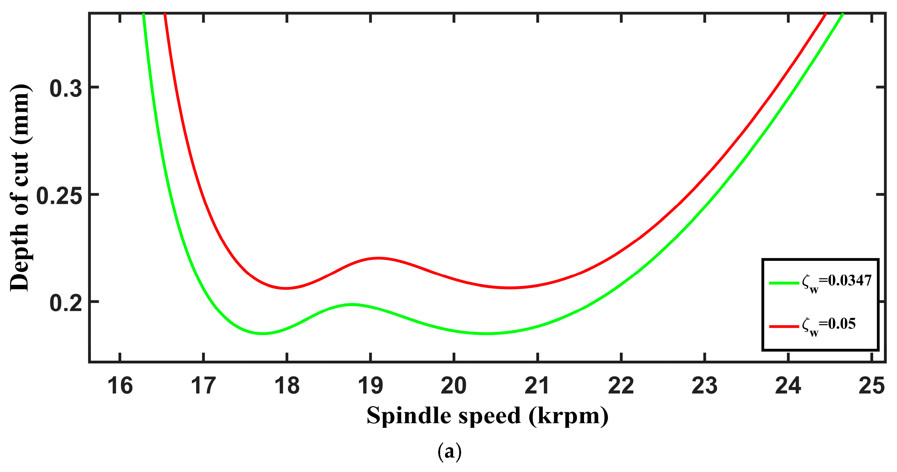
To overcome this limitation, a max–min optimization strategy was developed to determine the optimal TMD tuning parameters by achieving equal-trough stability lobes over a range of workpiece dynamic conditions. The optimized TMD substantially restores the deterioration in stability caused by variations in workpiece stiffness and damping, thereby providing a more uniform and robust stability boundary across the operating spindle-speed range. The study also demonstrates that the workpiece damping ratio has a pronounced influence on chatter stability when the tool and workpiece exhibit similar dynamic characteristics, whereas its effect is comparatively smaller for highly rigid or highly compliant workpieces.
Experimental investigations provided proof-of-concept support for the underlying structural dynamic mechanism of the proposed TMD, with the measured responses demonstrating resonance splitting and substantial attenuation of the dominant vibration response under different workpiece stiffness conditions. However, the experiments were not designed to directly validate the theoretically predicted stability–lobe boundaries through systematic cutting tests over multiple spindle speeds and depths of cut. Therefore, the reported improvements in limiting depth of cut and stability boundaries should be interpreted as predictions of the analytical model rather than as experimentally validated chatter stability limits. Furthermore, because the proof-of-concept experiments lacked independent replicates, statistical measures of variability and significance were not established. The long-term thermal and mechanical stability of the FDM-fabricated PLA absorber was also not investigated, and potential variations in its stiffness and damping due to thermal exposure, viscoelastic relaxation, and cyclic loading remain to be quantified.
Future work will therefore focus on repeated cutting experiments over a wider range of spindle speeds and depths of cut to directly compare the predicted and experimentally determined chatter–stability boundaries, together with statistical uncertainty analysis and long-term characterization of the absorber properties. The present three-degree-of-freedom model will also be extended to incorporate multiple structural modes of the cutting tool and workpiece, continuous variations in workpiece dynamics caused by material removal, and uncertainty and parameter drift in TMD stiffness and damping. Further development will investigate real-time identification of the evolving tool–workpiece dynamics and adaptive optimization of TMD parameters for potential integration into smart machining systems. These developments are expected to improve the robustness and practical applicability of the proposed optimization-based TMD design methodology for chatter suppression under varying machining conditions.




 ,
,