Article

Surface Morphology of Laser-Assisted Nanomachining of Silicon Carbide

1
Industrial Artificial Intelligence Technology Research Center, Taiyuan Institute of Technology, Taiyuan 030008, China
2
School of Mechanical Engineering, Taiyuan University of Science and Technology, Taiyuan 030024, China
3
School of Mechanical and Precision Instrument Engineering, Xi’an University of Technology, Xi’an 710048, China
*
Author to whom correspondence should be addressed.
J. Manuf. Mater. Process. 2026, 10(9), 320; https://doi.org/10.3390/jmmp10090320 (registering DOI)
Submission received: 18 July 2026 / Revised: 15 August 2026 / Accepted: 20 August 2026 / Published: 27 August 2026

Abstract

Silicon carbide is a typical hard and brittle semiconductor material that is prone to high cutting resistance, surface defects, and subsurface damage during nanomachining. To reveal the atomic-scale material removal mechanism of 3C-SiC under low-power laser heating, a molecular dynamics model of single-crystal 3C-SiC cut by a diamond tool was established, and conventional cutting was compared with laser-assisted cutting. Under low-power laser irradiation, the evolution of system potential energy was generally similar to that observed in conventional cutting, indicating limited overall thermal disturbance. The average cutting force decreased from approximately 285 nN to 275 nN, while the maximum burr height was reduced by about 0.75 Å. In contrast, the chip pile-up height increased by approximately 1.68 Å, and the temperature under laser-assisted cutting was slightly higher than that under conventional cutting. The results indicate that moderate laser-induced thermal effects enhance atomic migration in the cutting region, reduce the resistance to material removal, and improve the flatness and edge quality of the machined surface. These findings provide theoretical insight into the mechanisms of the laser-assisted nanomachining of 3C-SiC.

1. Introduction

Nanomachining technology serves as the foundation for processing micro- and nanomaterials and fabricating microstructures and devices [1] and has seen significant progress in fields such as semiconductor chip manufacturing, medical devices, flexible materials, and micro- and nanorobotics, as shown in Figure 1. Many physical mechanisms involved in nanomachining, including friction behavior and the brittle-to-ductile transition, differ markedly from those in conventional macroscopic machining. Moreover, as the processing scale decreases, size effects and micro-wear become more pronounced in nanomachining.
Silicon carbide, as an important semiconductor and ceramic material, is widely used in the manufacturing of critical equipment, such as infrared detectors, military telescopes, photolithography equipment, and optical guidance heads for aircraft; the quality of its machining is key to the performance of high-end equipment [9]. However, due to the material’s poor machinability, defects such as crack propagation are prone to occur on its surface and subsurface. Such defects can further cause scattering and diffraction of the optical path in optical components, introduce impurities such as iron, copper, and cerium, and may also alter the refractive index, scattering characteristics, and mechanical strength of the optical materials [10]. Investigating the nanometric cutting mechanisms of silicon carbide, improving the machining quality of optical components, and reducing and suppressing subsurface damage are of great significance for meeting the demands of the high-end equipment industry.
As a third-generation semiconductor material, silicon carbide has attracted extensive attention, and numerous studies have been conducted on its machining methods [11,12]. Research on the effects of laser-assisted machining on material removal behavior, surface quality, and damage evolution has gradually expanded from experimental characterization to atomistic-scale mechanism analysis. Cao et al. [13] investigated the laser-assisted machining process of silicon carbide and, based on the characterization of surface integrity, tool wear, and chip morphology, classified the machining states into brittle machining, ductile machining, and thermal damage. They also validated regression models for surface roughness and tool wear under the ductile machining regime. Regarding the mechanism of laser–material interaction, Xie et al. [14] investigated the influence of femtosecond laser irradiation on material machining behavior from the perspective of atomic structure and found that laser-induced stress waves could promote the formation of a subsurface dislocation layer, while the evolution of the subsurface dislocation structure further affected the mechanical properties of the irradiated region. For the optimization of laser machining parameters, Amsellem et al. [15] employed a fiber-based picosecond laser manufacturing technique to investigate SiC machining under various laser parameters and determined suitable values for focal position, laser power, scanning speed, wobble frequency, wobble mode, and number of passes. Huang et al. [16] used molecular dynamics simulations to study the interaction of femtosecond laser irradiation with the surface of single-crystal 4H-SiC. Their results showed that femtosecond laser irradiation could induce subsurface voids and material decomposition, thereby weakening, to some extent, the high-hardness and high-brittleness characteristics of SiC and improving its machinability. Cai et al. [17] further employed molecular dynamics simulations to investigate laser-assisted scratching of 4H-SiC and systematically analyzed the effects of laser power on material damage, scratching force, stress distribution, chip morphology, dislocation evolution, and subsurface damage. They found that, at high power density, a transformation from 4H-SiC to the more stable 3C-SiC crystal structure occurred near partial dislocation lines, revealing the underlying mechanism of laser-assisted machining of 4H-SiC and providing theoretical guidance for its application.
This study aims to establish a theoretical framework for laser-assisted cutting of silicon carbide and to reveal, from an atomic perspective, the novel evolution patterns of material during the nanometric cutting of hard and brittle materials under energy field conditions. The mechanisms underlying nanomachining with high surface quality and near-zero damage are systematically investigated, with particular emphasis on surface formation and regulation. This study also seeks to develop new methods and processes for the nanometric cutting of hard and brittle materials with controllable cutting damage. The results are expected to provide the necessary theoretical and experimental foundations for the advancement of high-end equipment manufacturing and efficient nanometric cutting technologies. Furthermore, the theoretical and process-oriented exploration in this study is anticipated to offer theoretical guidance and technical support for the machining of other difficult-to-machine materials.

2. Numerical Approach

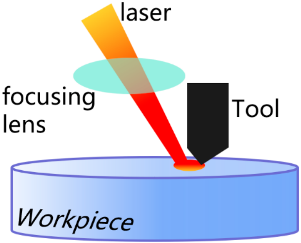
Laser-assisted machining is a manufacturing technique that employs a high-energy-density laser to soften materials, thereby significantly improving the machinability of hard and brittle materials and enabling high-efficiency, high-precision, and low-damage machining of difficult-to-cut materials [18,19]. A schematic diagram of the laser-assisted cutting principle is shown in Figure 2.
Laser-assisted machining technologies can be broadly classified into two categories, pre-laser-assisted machining and in situ laser-assisted machining. In pre-laser-assisted machining, the laser is employed to preheat the workpiece surface and soften the material; however, the relatively large heat-affected zone induced by the laser power renders the process difficult to control. In situ laser-assisted machining is a technique in which the laser beam passes through the cutting tool and acts simultaneously with the shearing and material removal action. The thermal effects of the in situ laser during machining can modify the instantaneous cutting conditions, thereby effectively eliminating surface defects caused by variations in crystal orientation [20].

3. Molecular Dynamics Model

Single-crystal SiC has more than 200 polytypes, among which the 3C, 4H, and 6H structures are the most common. In this study, the 3C-SiC polytype is adopted. 3C-SiC, also known as β-SiC, has a cubic crystal structure belonging to the F43m space group. It exhibits many outstanding properties, including high thermal conductivity, high carrier mobility, and excellent mechanical performance, and therefore holds broad application prospects in fields such as semiconductor devices, optoelectronic devices, and high-temperature applications.
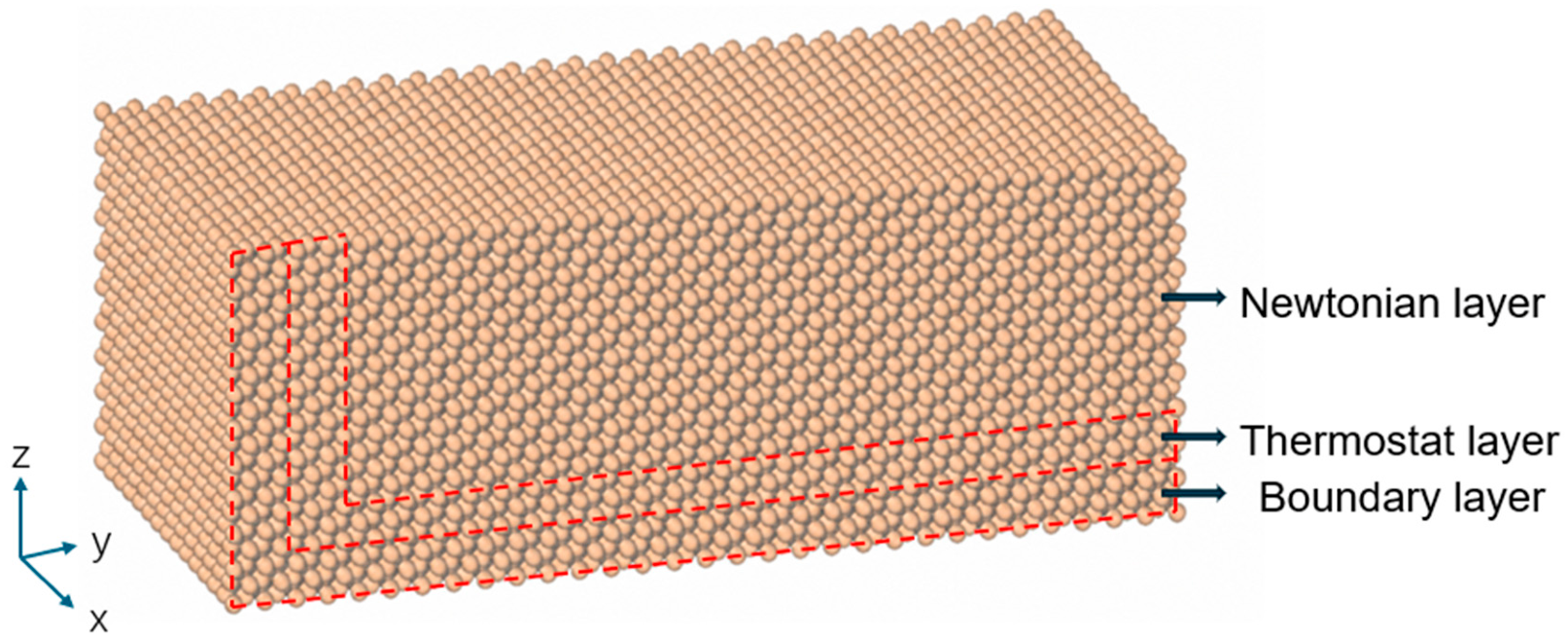
The single-unit-cell model was replicated along the x, y, and z directions to construct a workpiece with dimensions of 14 a × 30 b × 10 c, where a, b, and c denote the lattice constants along the three crystallographic directions, all of which are 4.36 Å. The resulting workpiece model is shown in Figure 3. Its dimensions along the x, y, and z directions are 61 Å × 130.8 Å × 43.6 Å, respectively, and the model contains a total of 35,375 atoms. The x-, y-, and z-axes correspond to the [100], [010], and [001] crystallographic directions, respectively. Periodic boundary conditions were applied along the x direction to reduce finite-size effects. The workpiece was divided from the interior to the exterior into three regions: the Newtonian layer, thermostat layer, and boundary layer. The boundary layer was located at the outermost region of the model, and its atoms were fixed to maintain structural stability. The thermostat layer was positioned between the Newtonian and boundary layers and was used to mimic heat transfer and dissipation from the local machining region into the bulk material of a macroscopic workpiece. The Newtonian layer constituted the primary region in which cutting, plastic deformation, bond breaking, atomic migration, and chip formation occurred, and the motion of atoms in this region followed Newton’s second law. The diamond cutting tool had a length and height of 75 Å and a width of 20 Å along the x direction. Both the rake angle and clearance angle were set to 10°, and the cutting-edge radius was 35 Å. The diamond tool was initially positioned 36 Å above the workpiece to avoid interactions between the tool and workpiece atoms at the initial stage. The detailed model parameters are summarized in Table 1.
The Tersoff potential can accurately describe the interactions associated with Si-Si, Si-C, and C-C bonds. In the present simulation, the Tersoff potential was employed to describe the interatomic interactions within the SiC workpiece, while the Morse potential was used to characterize the interactions between the C atoms of the diamond tool and the Si and C atoms of the SiC workpiece [21]. The diamond tool was treated as a rigid body, and tool wear was neglected because it was not the focus of the present study. The corresponding potential-function parameters are listed in Table 2.
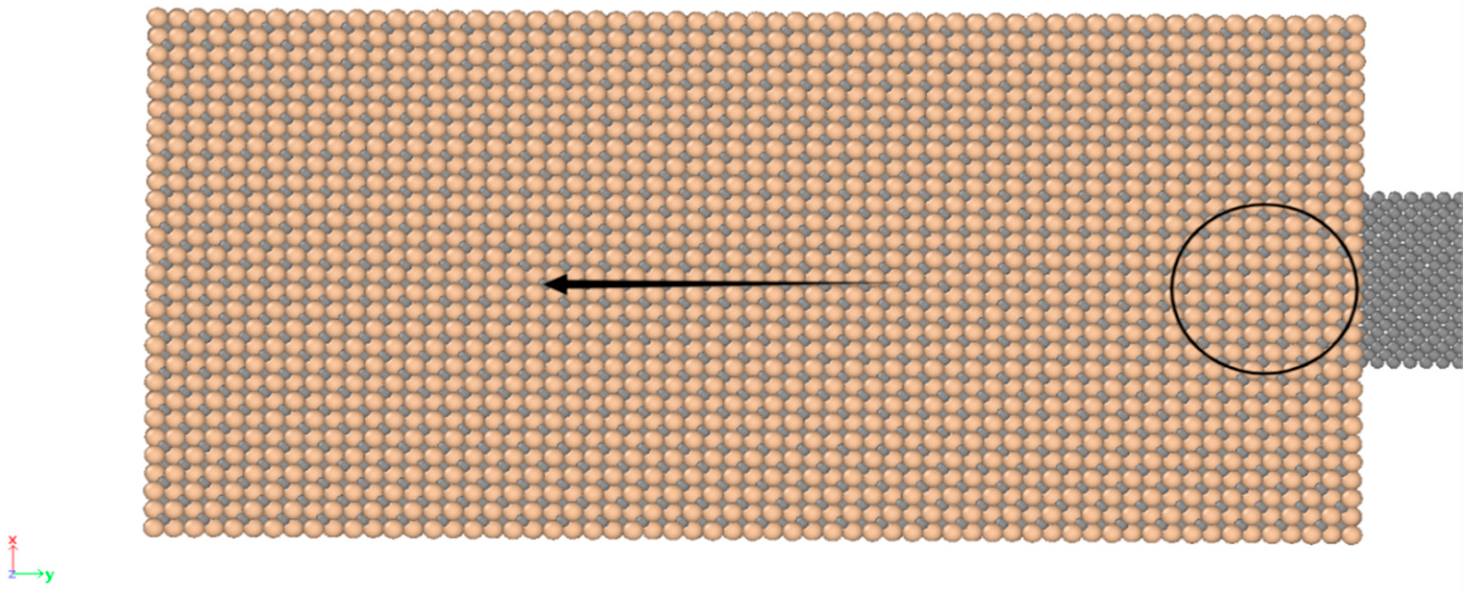
After constructing the MD model, the system energy was minimized using the conjugate gradient method. The initial temperature was set to 293 K, and the system was evolved under the NVE ensemble. Laser heating was implemented in LAMMPS using the fix heat command, in which the laser power was controlled by adjusting the amount of energy introduced per unit time. In the present model, only the thermal softening effect induced by laser irradiation was considered. The heated region was defined as a cylindrical zone with a height of 10 Å and a radius of 10 Å, corresponding to the 20 Å width of the cutting tool. The scanning speed of the laser-irradiated region was set to 1 Å/ps, equivalent to 100 m/s, which was identical to the cutting speed of the tool. The laser power density was set to 2.55 × 10⁷ W/cm2. The initial separation between the laser-irradiated region and the cutting tool along the y direction was 15 Å. During the simulation, the cylindrical laser region moved from an initial displacement of 0 Å to a final displacement of 120 Å. A schematic illustration of the laser-irradiated region is shown in Figure 4. The cutting tool moved along the negative y direction.

4. Results and Discussion

4.1. Analysis of System Potential Energy

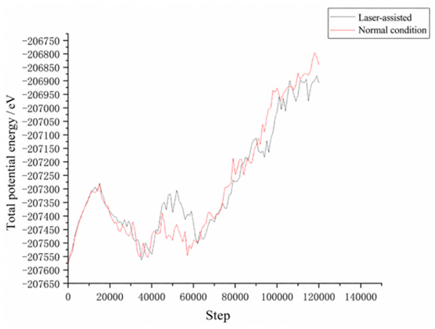
In molecular dynamics simulations, the system potential energy reflects the interatomic interaction energy and the degree of structural stability of the crystal lattice. During the cutting process, compression, shearing, and friction between the tool and the workpiece cause workpiece atoms to deviate from their equilibrium positions, leading to lattice distortion, defect formation, and localized amorphization, which in turn result in changes to the system potential energy. By analyzing the evolution of potential energy throughout the cutting process, the characteristics of internal structural damage and energy accumulation under different cutting conditions can be elucidated. Figure 5 presents the relationship between the total potential energy and the number of simulation steps for both conventional cutting and laser-assisted cutting. During the cutting process, bond breaking and formation occur, accompanied by energy release and dissipation. A comparison of the two cases reveals that after approximately 60,000 simulation steps, the atomic compression in the cutting zone intensifies, giving rise to a rapid increase in potential energy. Under the two conditions compared, the potential energy evolution in laser-assisted cutting is essentially consistent with that in conventional cutting. However, the overall system potential energy under laser-assisted cutting is slightly higher than that under conventional cutting, suggesting that the laser heating enhances the thermal activation and structural rearrangement of atoms in the cutting region, thereby increasing the degree of internal energy accumulation within the material.

4.2. Surface Morphology Analysis

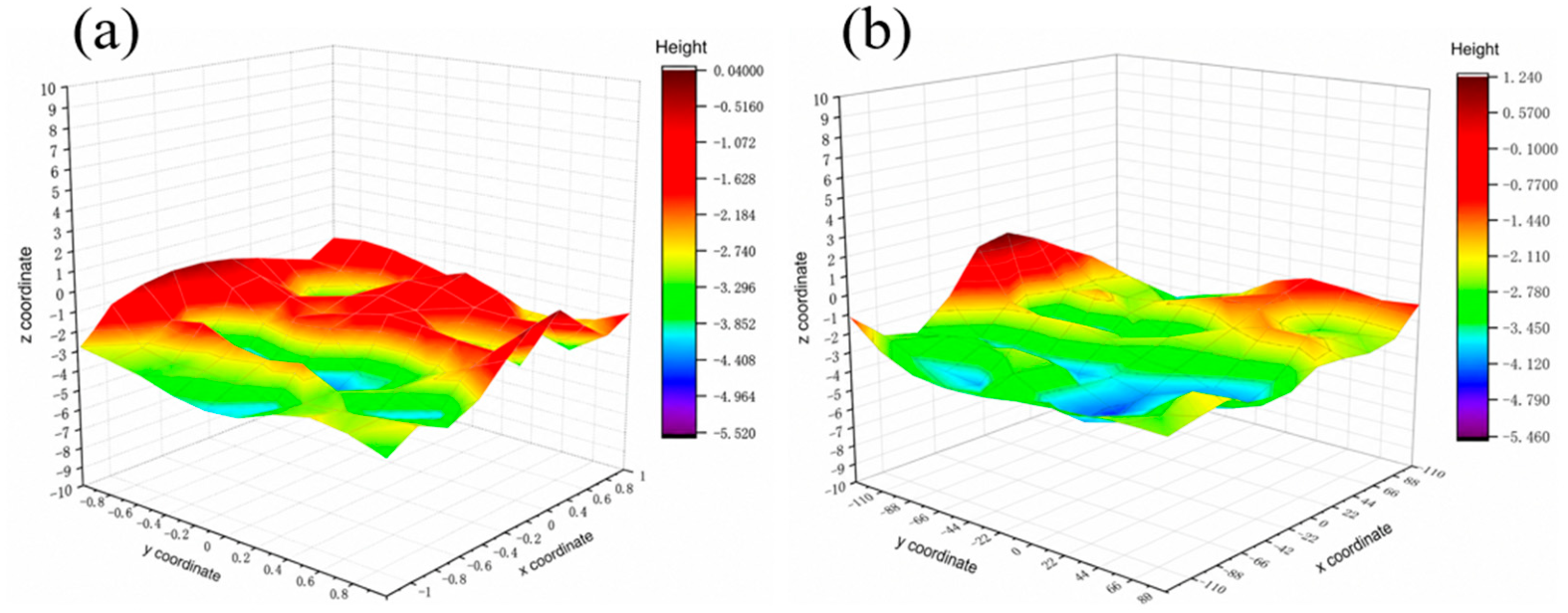
The surface morphology of the 3C-SiC workpiece after diamond-tool machining determines the resulting surface roughness. The three-dimensional surface topographies of the workpieces after conventional cutting and laser-assisted cutting are shown in Figure 6. A comparison of the two conditions indicates that the surface obtained by laser-assisted cutting is generally flatter and exhibits better surface quality than that produced by conventional cutting. To further quantify the surface roughness, the Z-coordinates of the atoms on the machined groove surface were extracted at a cutting distance of 100 Å, and the surface roughness was calculated using the following equation:
S a = 1 N i = 1 N Z i Z ¯
where Sa represents the areal arithmetic mean surface roughness, Zi is the Z-coordinate of the ith atom on the machined groove surface, Z ¯ is the mean Z-coordinate of the selected surface atoms, and N is the total number of selected surface atoms. The calculated surface roughness values for conventional cutting and laser-assisted cutting were 0.846 Å and 0.824 Å, respectively, indicating a slight reduction in surface roughness under laser assistance; this is consistent with the conclusion reported by Cao et al. that laser-assisted cutting can improve the machined surface quality [13]. This reduction is mainly attributed to the local thermal effect induced by laser irradiation, which facilitates material removal under the action of the cutting tool and thereby reduces local height fluctuations on the machined surface. Consequently, the laser-assisted cutting condition produces a relatively smoother surface than conventional cutting.

4.3. Chip Formation Analysis

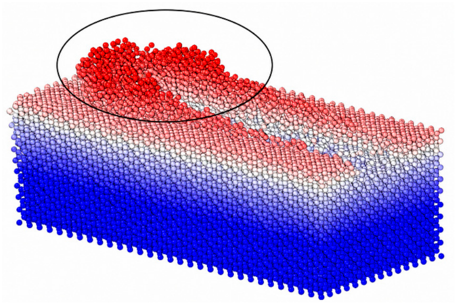
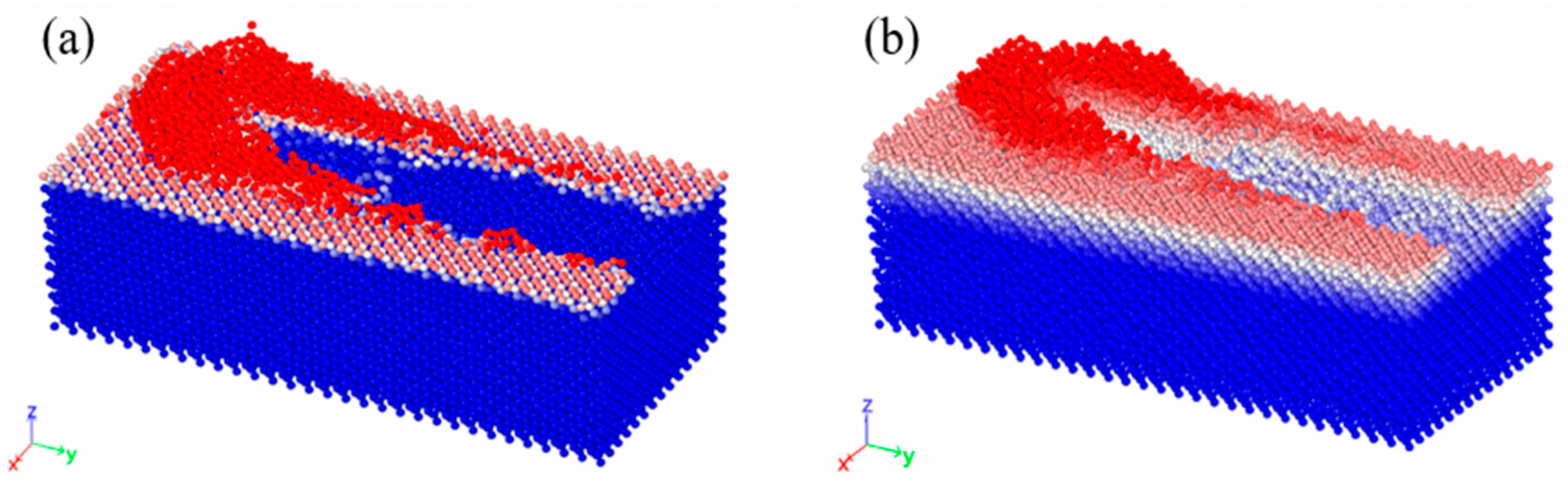
During the machining process, the workpiece material is subjected to impact and extrusion from the diamond tool, resulting in the release of energy from the lattice atoms. This energy breaks the covalent bonds between the workpiece atoms, leading to their fracture and the consequent formation of chips. Figure 7 shows the chip morphology under conventional cutting and laser-assisted cutting conditions. It can be observed that after the SiC workpiece is subjected to extrusion and shearing by the diamond tool, the chip accumulation in front of the tool forms an arc-shaped chip cluster. The regions enclosed by the circles indicate the locations of chip accumulation.
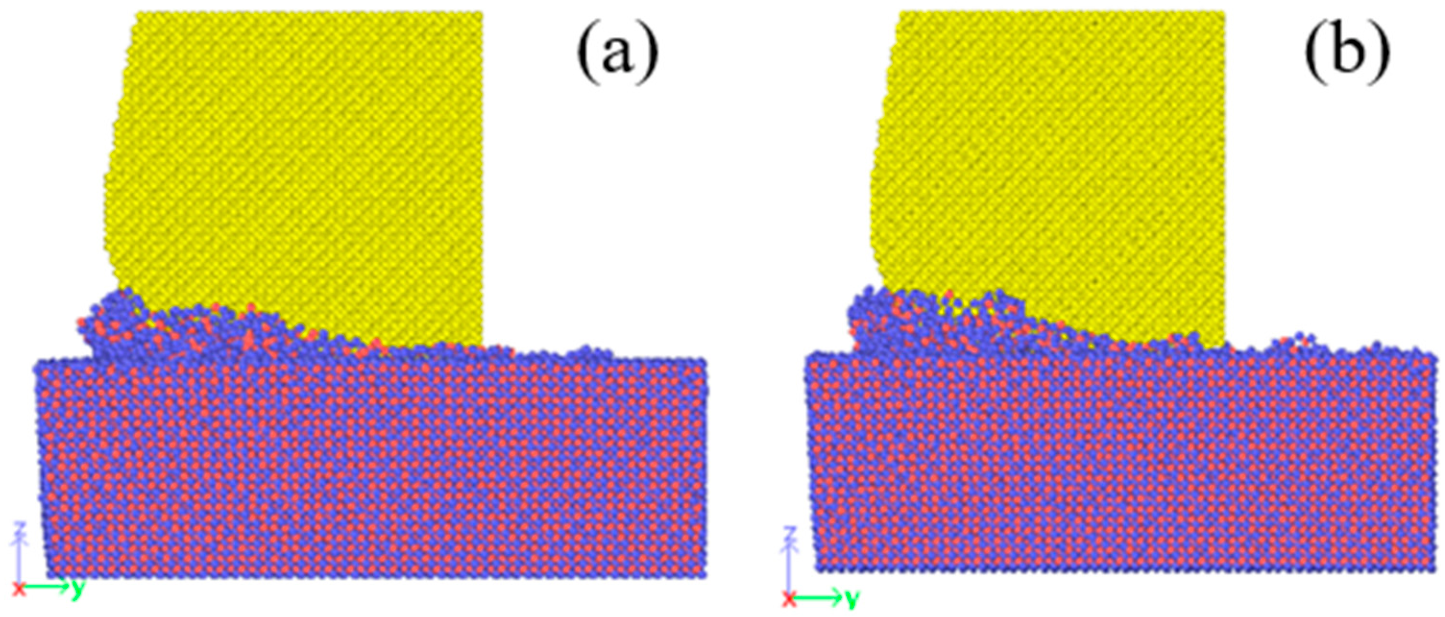
Figure 8 presents the chip heights obtained under conventional cutting and laser-assisted cutting. The chip height is defined as the vertical distance from the highest point of the chips formed after cutting the 3C-SiC workpiece to the original upper surface of the workpiece. The corresponding chip heights are 14.451 Å and 16.1277 Å, respectively. The irregular region directly in front of the diamond tool consists of residual chips generated during machining. This phenomenon arises from the continuous interaction between the diamond tool and the SiC workpiece throughout the cutting process. Because the hardness of the diamond tool is significantly higher than that of the workpiece material, the chips generated from the matrix are continuously pushed forward, while the chips on both sides of the cutting path also accumulate and move toward the front of the tool, eventually forming a pronounced chip pile-up. The results show that the chip height under laser-assisted cutting is slightly higher than that under conventional cutting. This difference may be attributed to the local thermal softening induced by laser irradiation. The input laser energy enhances the thermal motion of atoms in the cutting region and reduces the local structural stability, making the workpiece atoms more susceptible to migration under the combined extrusion and shearing actions of the cutting tool. Under the relatively low laser power employed in this study, the laser energy is insufficient to induce pronounced material ablation or direct material removal. Consequently, some atoms with enhanced mobility are continuously pushed toward the front of the tool during its advancement, resulting in a locally higher chip pile-up.

4.4. Cutting Force Analysis

In molecular dynamics simulations, the interatomic interaction forces determine the magnitude of the cutting force. Throughout the entire cutting process, the cutting force exhibits continuous fluctuations. This is attributed to the formation and annihilation of dislocations within the workpiece, which induce energy oscillations and consequently lead to force variations. The magnitude of the cutting force directly affects the surface quality of the workpiece, among other aspects.
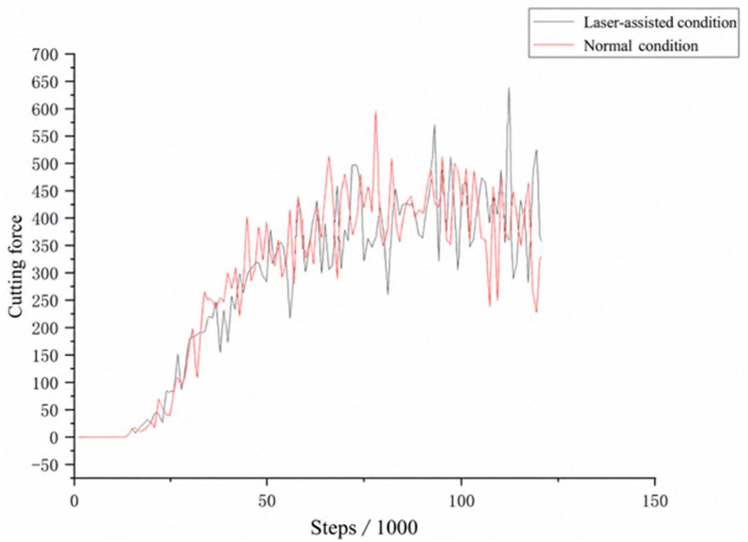
After the relaxation stage, the cutting process of the SiC workpiece was initiated. Before contact between the diamond tool and the SiC substrate, the cutting force components in the x, y, and z directions were approximately zero. For data processing, resultant forces below 0.0001 nN were treated as zero. The tool came into contact with the workpiece at approximately the 15,000th simulation step; therefore, the cutting force remained nearly zero before this point. Upon initial tool–workpiece contact, elastic and plastic deformation occurred in the workpiece, resulting in a rapid increase in the cutting force. The cutting force subsequently exhibited an approximately linear increase until around the 50,000th simulation step, after which it fluctuated around 350 nN. The average cutting forces under laser-assisted and conventional cutting were approximately 275 and 285 nN, respectively. The reduction in cutting force under laser assistance can be attributed to the local thermal effect induced by laser irradiation. The introduced laser energy enhances atomic thermal motion in the cutting region and facilitates atomic deformation and migration under the action of the tool, thereby reducing the resistance to material removal. This trend is consistent with the findings of Gao et al., who also reported a reduction in machining force under laser-assisted conditions [21]. The cutting force curves are shown in Figure 9.

4.5. Burr Morphology Analysis

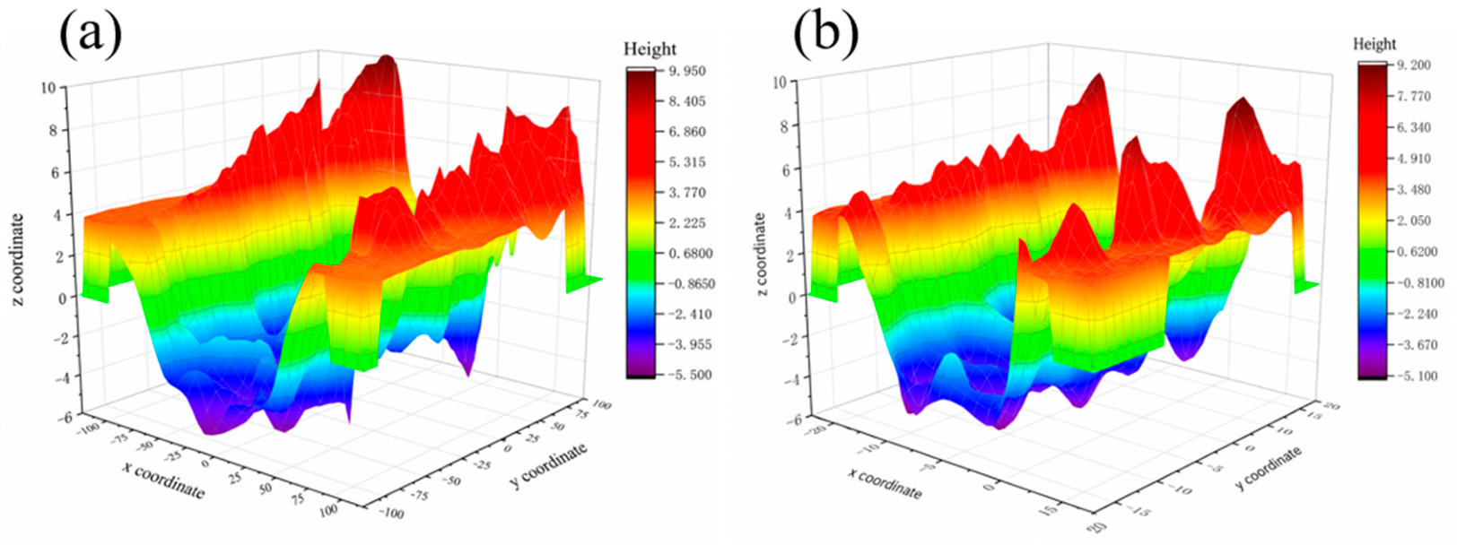
During the machining process, protrusions form on both sides of the cutting path after the tool cuts through the workpiece matrix; this phenomenon is referred to as burrs. Burrs are one of the key factors affecting the surface quality of the machined workpiece, and excessive burrs can adversely affect the final surface finish. To facilitate the observation of burrs, atomic positions were extracted and colored according to their coordinates along the z-direction, as shown in Figure 10, which presents the burr morphology. It can be observed that the burr height under laser-assisted cutting is lower than that under conventional cutting, indicating that the thermal softening effect of laser assistance is conducive to improving the cutting performance.
As shown in Figure 11, both the workpiece surfaces produced by conventional cutting and laser-assisted cutting exhibit certain undulations; however, the surface obtained under laser-assisted cutting is flatter. The maximum surface height under conventional cutting is approximately 9.95 Å, whereas that under laser-assisted cutting is approximately 9.20 Å. This indicates that laser assistance can reduce localized material accumulation and lower the peak surface height, thereby improving the surface quality of the workpiece to a certain extent.

4.6. Temperature Analysis

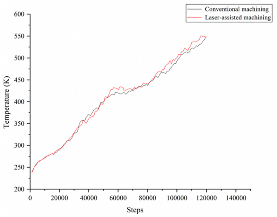
Temperature is an important parameter for characterizing the thermal state during the cutting process. As the diamond tool continuously interacts with the 3C-SiC substrate, atomic compression, shearing, and friction cause the temperatures of the tool and workpiece to gradually increase, as shown in Figure 12. Excessive cutting temperatures may adversely affect the machined surface quality. In the present study, the temperature under laser-assisted cutting is slightly higher than that under conventional cutting because additional thermal energy is introduced by laser irradiation, which enhances atomic thermal motion and leads to a temperature increase. This observation is consistent with the thermal effects reported by Huang et al. [16].

5. Conclusions

To investigate the microscopic mechanisms of the diamond tool cutting of 3C-SiC workpieces, molecular dynamics simulations were performed using LAMMPS to model both laser-assisted and conventional cutting processes. Based on the analysis and discussion from the following aspects, the main conclusions are drawn as follows:
(1)
Regarding cutting forces, both conventional and laser-assisted cutting exhibit significant fluctuations, with similar trends, growth rates, and fluctuation amplitudes. Compared with conventional cutting, the average cutting force under laser-assisted cutting is slightly lower, indicating that, under the laser-assisted conditions defined in this study, the thermal effect of the laser plays a role in reducing cutting resistance.
(2)
In terms of surface quality, analysis of the surface topography data of the machined workpiece reveals that laser-assisted cutting improves surface flatness. Compared with conventional cutting, the surface undulation under laser-assisted conditions is reduced, indicating that appropriate laser-assisted heating is beneficial for improving the surface quality after nanometric cutting of 3C-SiC.
(3)
Regarding chip accumulation behavior, pronounced material accumulation is observed in front of the diamond tool, resulting from the combined effects of continuous compression, shearing, and pushing of the workpiece atoms by the tool. The comparison shows that the chip height under laser-assisted cutting is higher than that under conventional cutting, with an increase of approximately 1.68 Å. This increase can be attributed to the local thermal softening induced by laser irradiation, which reduces the stability of the local atomic structure and facilitates atomic migration under the compression and shearing actions of the cutting tool. Consequently, more workpiece atoms are transported toward the front of the tool, resulting in a higher chip pile-up.
(4)
Regarding temperature, the temperature variation patterns of the workpiece are essentially consistent under both cutting conditions, with minimal overall temperature differences. Owing to the external heat input during laser-assisted cutting, the temperature in the cutting zone is slightly higher than that during conventional cutting.
(5)
Regarding burr formation, the burr morphology on both sides of the workpiece is improved under laser-assisted cutting. Compared with conventional cutting, the maximum burr height under laser-assisted conditions is reduced by approximately 0.75 Å, and the burr distribution becomes more uniform. These results indicate that laser-assisted heating helps suppress edge protrusions caused by localized atomic accumulation, thereby improving the quality of the machined edges.
This study investigated the effects of laser assistance on the nanocutting behavior of 3C-SiC at the atomic scale; however, several aspects remain to be further explored. Future studies will consider the effects of laser power, scanning velocity, and cutting parameters on material removal behavior, with particular emphasis on energy transfer, subsurface damage, and atomic structural evolution during the cutting process. In addition, nanocutting experiments could be conducted to validate the molecular dynamics simulation results and further elucidate the material removal mechanisms of the laser-assisted nanocutting of 3C-SiC.

Author Contributions

Conceptualization, J.R.; methodology, Z.Z.; software and simulation, Z.Z.; validation, Z.Z.; formal analysis, Z.Z.; investigation, Z.Z.; resources, J.R.; data curation, Z.Z.; writing—original draft preparation, J.R. and P.Z.; writing—review and editing, P.Z.; project administration, J.R.; funding acquisition, J.R. All authors have read and agreed to the published version of the manuscript.

Funding

This research was funded by the Fundamental Research Program of Shanxi Province, grant number 202303021212280; the Joint Fund Project of the Basic Research Program of the Shanxi Provincial Department of Science and Technology, grant number 202503011212010; and the Traditional Chinese Medicine Industry Modernization Support Project of the Shanxi Provincial Health Commission, grant number 2026zyycy14.

Data Availability Statement

The data that support the findings of this study are available on request from the corresponding author.

Acknowledgments

The authors gratefully acknowledge the support provided by the Fundamental Research Program of Shanxi Province (grant No. 202303021212280), the Jointly Funded Project of the Basic Research Program of the Shanxi Provincial Department of Science and Technology (grant No. 202503011212010), and the Traditional Chinese Medicine Industry Modernization Support Project of the Shanxi Provincial Health Commission (grant No. 2026zyycy14).

Conflicts of Interest

The authors declare no conflicts of interest.

References

  1. Herrer, L.; Martín, S.; Cea, P. Nanofabrication techniques in large-area molecular electronic devices. Appl. Sci. 2020, 10, 6064. [Google Scholar] [CrossRef] [Scilit]
  2. Mullen, E.; Morris, M.A. Green nanofabrication opportunities in the semiconductor industry: A life cycle perspective. Nanomaterials 2021, 11, 1085. [Google Scholar] [CrossRef] [Scilit]
  3. Lu, Z.; Zheng, J.; Shi, J.; Zeng, B.; Yang, Y.; Hong, W.; Tian, Z. Application of micro/nanofabrication techniques to on-chip molecular electronics. Small Methods 2021, 5, 2001034. [Google Scholar] [CrossRef] [Scilit]
  4. Kim, M.; Brown, D.K.; Brand, O. Nanofabrication for all-soft and high-density electronic devices based on liquid metal. Nat. Commun. 2020, 11, 1002. [Google Scholar] [CrossRef] [Scilit]
  5. Wang, Y.; Wang, R.; Wan, S.; Wang, Q.; Kim, M.J.; Ding, D.; Wu, W. Scalable nanomanufacturing and assembly of chiral-chain piezoelectric tellurium nanowires for wearable self-powered cardiovascular monitoring. Nano Futures 2019, 3, 011001. [Google Scholar] [CrossRef] [Scilit]
  6. Wang, C.; Harder, P.; Iyisan, N.; Li, B.; Hiendlmeier, L.; Wolfrum, B.; Özkale, B. A multiscale approach to assess thermomechanical performance and force generation in nanorobotic microgels. Nanoscale 2024, 16, 5222–5231. [Google Scholar] [CrossRef] [Scilit]
  7. Llopis-Lorente, A.; Garcia-Fernandez, A.; Lucena-Sánchez, E.; Díez, P.; Sancenón, F.; Villalonga, R.; Wilson, D.A.; Martínez-Máñez, R. Stimulus-responsive nanomotors based on gated enzyme-powered Janus Au–mesoporous silica nanoparticles for enhanced cargo delivery. Chem. Commun. 2019, 55, 13164–13167. [Google Scholar] [CrossRef] [Scilit]
  8. Leinen, P.; Esders, M.; Schütt, K.T.; Wagner, C.; Müller, K.-R.; Tautz, F.S. Autonomous robotic nanofabrication with reinforcement learning. Sci. Adv. 2020, 6, eabb6987. [Google Scholar] [CrossRef] [Scilit]
  9. Jiang, Z.D.; Li, C.S.; Sun, L.; Duan, D.Z.; Kang, C.W.; Chen, S.S.; Lin, Q.J.; Yang, S.M. Development of ultra-precision machining technology and equipment for high-end optical components. Strateg. Study CAE 2023, 25, 131–141. (In Chinese) [Google Scholar] [CrossRef] [Scilit]
  10. Guo, D.M.; Kang, R.K. Research status and development trend of ultra-precision grinding technology for semiconductor substrates. J. Mech. Eng. 2023, 59, 299–329. (In Chinese) [Google Scholar]
  11. Geng, Z.; He, Y.; Fang, F. Study on surface integrity of RS-SiC under photocatalysis/vibration-assisted finishing. J. Manuf. Process. 2025, 134, 384–393. [Google Scholar] [CrossRef] [Scilit]
  12. Zhao, X.; Tang, Y.; Chen, K.; Cai, Y.; Liang, X.; Liu, Z.; Li, D. Bauschinger effect in nano-grinding of 3C-SiC: A molecular dynamics study. Wear 2025, 571, 205847. [Google Scholar] [CrossRef] [Scilit]
  13. Cao, C.; Zhao, Y.; Zhang, G.; Li, Z.; Zhao, C.; Yu, H.; Zhao, D.; Zhang, H.; Dai, D. Experimental study of plastic cutting in laser-assisted machining of SiC ceramics. Opt. Laser Technol. 2024, 169, 110098. [Google Scholar] [CrossRef] [Scilit]
  14. Xie, J.; Yan, J.; Zhu, D.; He, G. Atomic-level insight into the formation of subsurface dislocation layer and its effect on mechanical properties during ultrafast laser micro/nano fabrication. Adv. Funct. Mater. 2021, 32, 2108802. [Google Scholar] [CrossRef] [Scilit]
  15. Amsellem, W.; Sarvestani, H.Y.; Pankov, V.; Martinez-Rubi, Y.; Gholipour, J.; Ashrafi, B. Deep precision machining of SiC ceramics by picosecond laser ablation. Ceram. Int. 2023, 49, 9592–9606. [Google Scholar] [CrossRef] [Scilit]
  16. Huang, Y.; Zhou, Y.; Li, J.; Zhu, F. Femtosecond laser surface modification of 4H-SiC improves machinability. Appl. Surf. Sci. 2023, 615, 156436. [Google Scholar] [CrossRef] [Scilit]
  17. Cai, J.; Guo, X.; Gao, D. Probing the surface/subsurface damage mechanism of laser-assisted single-grain scratching of 4H-SiC based on molecular dynamics. Appl. Surf. Sci. 2025, 689, 162421. [Google Scholar] [CrossRef] [Scilit]
  18. Javed, A.O.M.; Rashid, B.A. Laser-assisted micromachining techniques: An overview of principles, processes, and applications. Adv. Mater. Process. Technol. 2025, 11, 1583–1626. [Google Scholar] [CrossRef] [Scilit]
  19. Liu, Q.; Liu, J.; Ming, Z.; Cui, B.; Wang, J. Research progress on laser-assisted precision machining technology. Micromachines 2025, 16, 173. [Google Scholar] [CrossRef] [Scilit]
  20. Xing, Y.T.; Ye, H.S.; Du, X. Research progress on energy-field-assisted ultra-precision diamond cutting technology: Invited review. Infrared Laser Eng. 2026, 55, 11–29. (In Chinese) [Google Scholar]
  21. Gao, T.; Li, Q.; Dong, K.; Liu, G.; Yan, W.; Huang, J.; Song, H.; Zhang, Z. Molecular simulation study of the subsurface damage mechanism of silicon carbide/aluminum composites during laser-assisted grinding. Phys. B Condens. Matter 2025, 713, 417394. [Google Scholar] [CrossRef] [Scilit]
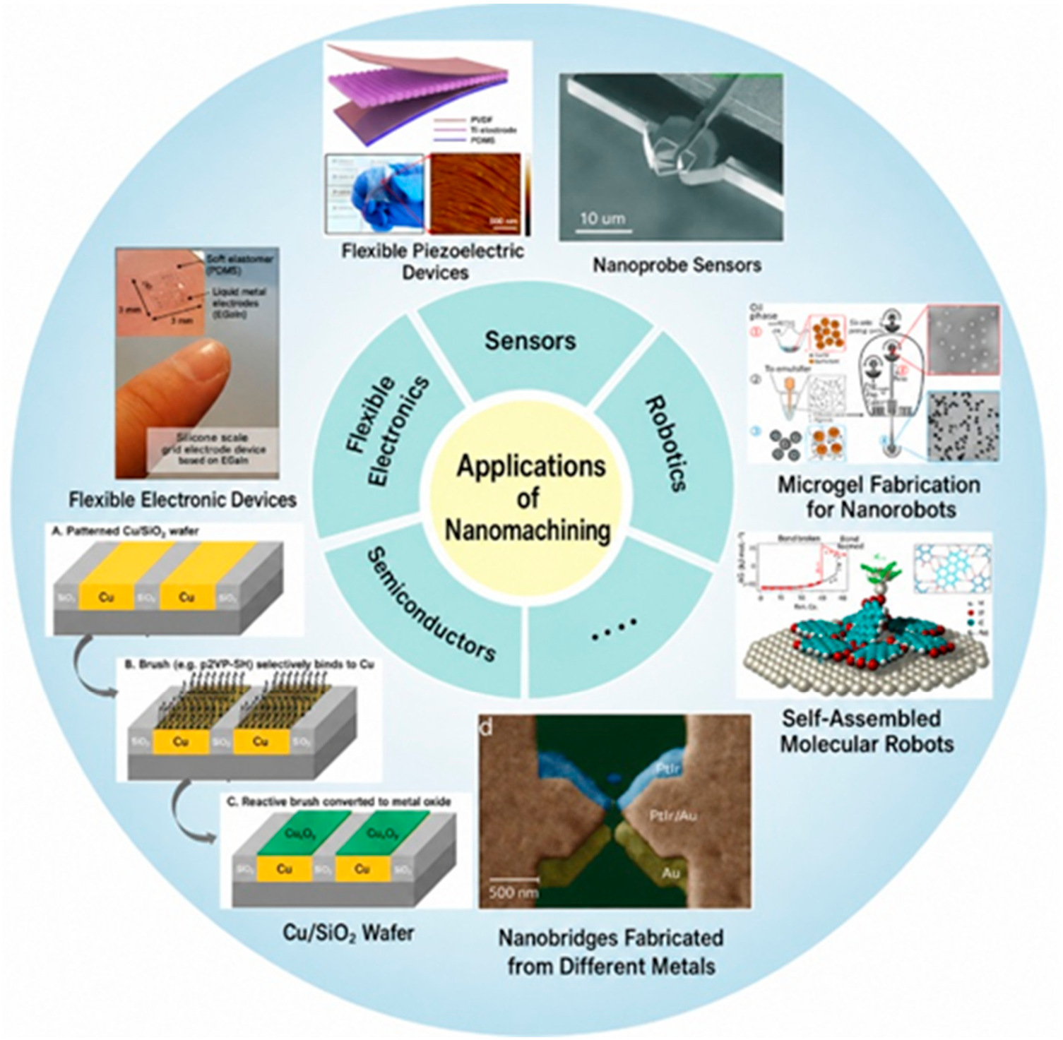
Figure 1. Applications of nanomanufacturing in various industries [2,3,4,5,6,7,8].
Jmmp 10 00320 g001
Figure 2. Schematic diagram of laser heating-assisted cutting.
Jmmp 10 00320 g002
Figure 3. 3C-SiC workpiece model.
Jmmp 10 00320 g003
Figure 4. Schematic of the laser irradiation region.
Jmmp 10 00320 g004
Figure 5. Potential energy curves under two cutting conditions.
Jmmp 10 00320 g005
Figure 6. Surface morphology of the machined workpiece: (a) conventional machining; (b) laser-assisted machining.
Jmmp 10 00320 g006
Figure 7. Schematic of the arc-shaped region during the cutting process.
Jmmp 10 00320 g007
Figure 8. Chip accumulation distribution: (a) conventional cutting; (b) laser-assisted cutting.
Jmmp 10 00320 g008
Figure 9. Comparison of cutting forces.
Jmmp 10 00320 g009
Figure 10. (a) Conventional cutting. (b) Laser-assisted cutting.
Jmmp 10 00320 g010
Figure 11. (a) Surface image under conventional cutting. (b) Surface image under laser-assisted cutting.
Jmmp 10 00320 g011
Figure 12. Variation in temperature with simulation steps.
Jmmp 10 00320 g012
Table 1. Simulation parameters used in the molecular dynamics simulation.
FactorWorkpieceTool
Material type3C-SiCJmmp 10 00320 i001
Potential usedTersoff, Morse
EnsembleNVE
Dimension14 a × 30 b × 10 c
Atom number35,37518,675
Initial temperature293 K
Timestep1 fs
Cutting speed100 m/s
Cutting depth3.1 Å
Cutting distance120 Å
Laser power density2.55 × 107 W/cm2
Tool rake angleα0 = 10°
Tool clearance angleγ0 = 10°
Tool edge radiusr = 35 Å
Table 2. Parameters of the Morse potential function.
SystemD (ev)A (1/Å)R (Å)
C-C2.4232.5552.522
Si-C0.4354.64871.9475
Disclaimer/Publisher’s Note: The statements, opinions and data contained in all publications are solely those of the individual author(s) and contributor(s) and not of MDPI and/or the editor(s). MDPI and/or the editor(s) disclaim responsibility for any injury to people or property resulting from any ideas, methods, instructions or products referred to in the content.