Article

Tool Wear and Machinability Assessment of Ti-6Al-4V with Cemented Carbide Tools During Large Overhang Milling with Varying Shank Lengths

1
State Key Laboratory of Cemented Carbide, Zhuzhou Cemented Carbide Group Corp. Ltd., Zhuzhou 412007, China
2
Zhuzhou Cemented Carbide Cutting Tools Co., Ltd., Zhuzhou 412007, China
3
School of Mechanical Engineering, Shandong University, Jinan 250061, China
4
Key Laboratory of High Efficiency and Clean Mechanical Manufacture of Ministry of Education, Jinan 250061, China
5
School of Airspace Science and Engineering, Shandong University, Weihai 264209, China
*
Authors to whom correspondence should be addressed.
These authors contributed equally to this work.
J. Manuf. Mater. Process. 2026, 10(5), 162; https://doi.org/10.3390/jmmp10050162
Submission received: 16 April 2026 / Revised: 30 April 2026 / Accepted: 2 May 2026 / Published: 5 May 2026

Abstract

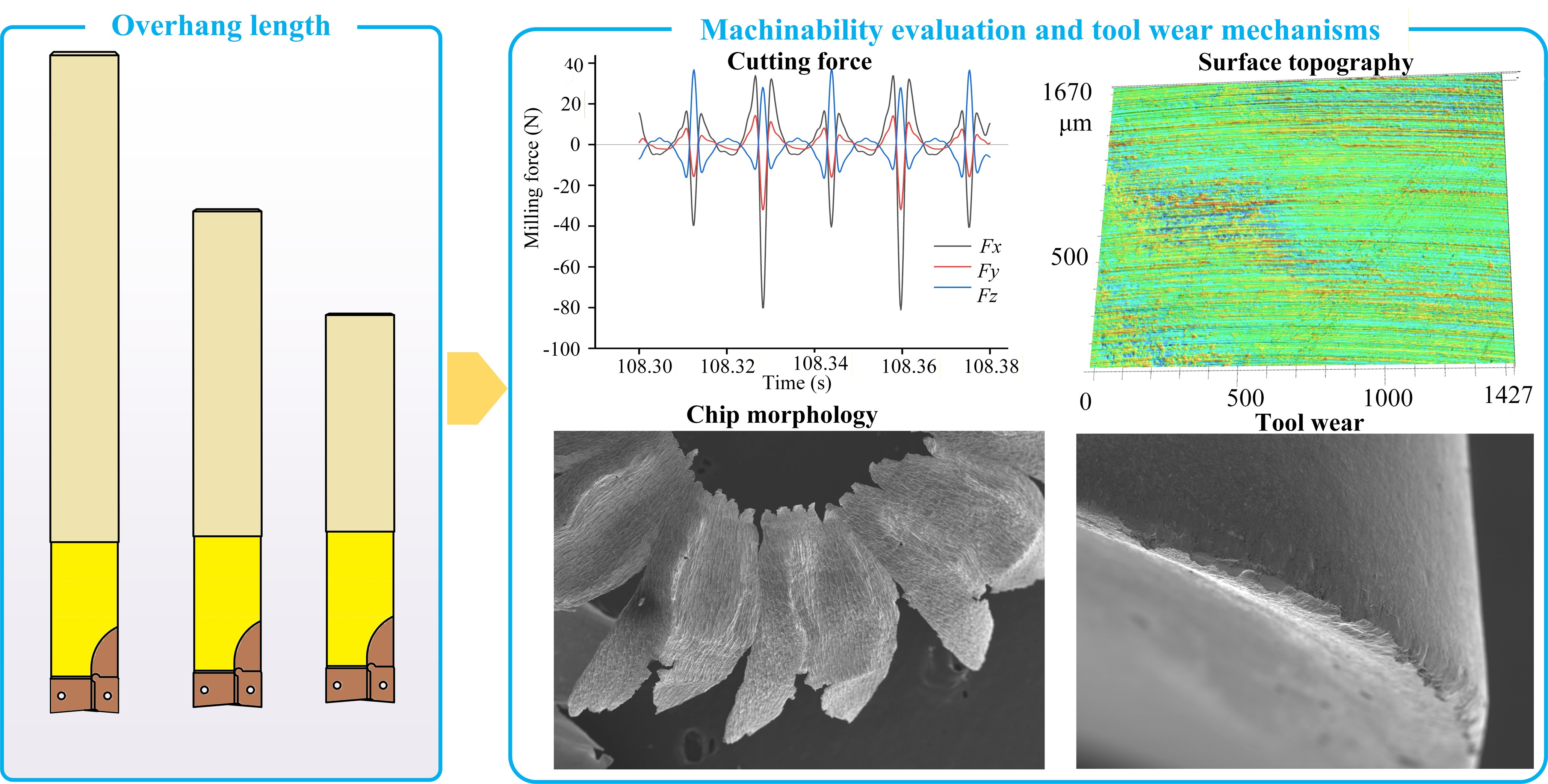
Large overhang milling cutters face challenges, including poor cutting stability and surface quality when machining deep-cavity parts in aerospace and other industries. The combined interactions between overhang and process parameters significantly influence machining performance and the tool wear mechanism. In this study, the coupled effects of tool overhang length and feed per tooth on milling force, surface topography, chip morphology, and tool wear mechanism were systematically investigated under typical large overhang conditions. The tool stiffness decreased with increasing overhangs; the feed force decreased by approximately 32.4%~49.48%; and the chip morphology changed from continuous bands to fractures. The feed force increased by approximately 25.11%~67.34% with increasing the feed per tooth, resulting in reduced surface quality and accelerated tool wear. The novelty of this work lies in quantitatively revealing the coupling mechanism between overhang length and feed rate in large overhang milling, providing a theoretical basis for process optimization. The findings are directly applicable to the optimization of machining parameters for deep-cavity components such as aero-engine casings and optical mold cavities, where tool overhang is a critical factor affecting productivity and surface integrity. This study provides a theoretical foundation and experimental reference for optimizing process parameters when milling titanium alloy with long-overhang milling cutters.

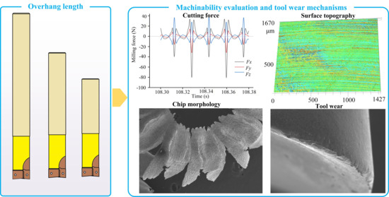
Graphical Abstract

1. Introduction

Titanium alloys serve as an important metallic material that has received close attention from engineers and industrial manufacturers. Titanium alloys are divided into α alloys, β alloys, α-β alloys, and near-α alloys based on differences in microstructure and phase composition [1,2,3]. Ti-6Al-4V (approximately 6% aluminum and 4% vanadium by weight), serving as a typical α-β dual-phase alloy, has been commonly employed in high-end manufacturing industries such as aircraft engines, biomedicine, and precision instruments for the high specific strength, superior corrosion resistance, and outstanding thermal strength [4,5,6]. However, Ti-6Al-4V is also recognized as a typical hard-to-machine material. The low thermal conductivity and high chemical reactivity readily lead to sharp increases in cutting force and temperature during machining. Such problems cause rapid tool wear, shortened tool life, and deteriorated surface quality, severely limiting its potential application in precision manufacturing [7,8,9].
Large overhang milling cutters are often used to manufacture parts with deep cavities, deep holes, and complex curved surfaces, such as aero-engine blades and optical mold cavities [10]. With increasing demands for manufacturing precision, greater challenges have been posed for the stability of the milling process and the control of surface quality. Due to the high length-to-diameter ratio and relatively low structural rigidity, long-overhang milling cutters are prone to vibration during machining, which can significantly impact surface quality. Quintana and Ciurana [11] provided a comprehensive review of chatter mechanisms in machining processes, highlighting that tool dynamics play a decisive role in stability limits. The overhang length is one of the key parameters affecting the dynamic characteristics of the milling system, and its changes significantly alter the shape of the stability envelope and the amplitude of the critical cutting depth. As the overhang of the same tool increases, the stability boundary of critical cutting depth shifts significantly downward, and the risk of chatter increases substantially [12]. Mishra et al. [13] examined the influence of overhang on workpiece surface quality and found that excessive or insufficient overhang led to a decrease in surface quality. Wojciechowski et al. [14] further revealed the mechanism of overhang on surface morphology. They found that when machining with short overhang tools, surface morphology was mainly controlled by the motion-geometric model. Meanwhile, dynamic tool deflection became the primary factor affecting surface morphology when machining with long overhang tools.
Surface integrity is one of the core indicators for evaluating the final machining quality of parts [15]. The surface quality and tool wear are closely related to milling process parameters [16,17]. Zhang et al. [18] studied the correlation between process parameters and cutting forces in nickel-based superalloy machining. They found that increasing cutting depth and feed rate led to higher cutting forces, while raising cutting speed resulted in a decreasing trend of cutting forces. Wu et al. [19] explored the effects of process parameters on surface roughness in micro-milling of additively manufactured Ti6Al4V. They revealed that surface roughness decreased with increasing spindle speed, while it increased with increasing milling depth. Zhu et al. [20] found that when milling 6061 aluminum alloy, a larger feed per tooth resulted in higher surface roughness and poorer surface quality. Güven et al. [21] investigated the influences of parameters on tool wear when milling high-temperature alloy Inconel 625. They found that feed rate was the main factor leading to tool wear. Tool wear is also a key factor affecting surface integrity, and increased wear leads to a decrease in surface quality [22]. Current research mainly focuses on the effects of process parameters such as spindle speed, feed rate, and depth of cut, while systematic exploration of tool overhang effects remains insufficient.
Tool overhang, as a key process parameter reflecting the machining process, has attracted attention from some scholars. Kuram et al. [23] explored the influence of tool overhang length on machining performance during micro-milling of Inconel 718. They found that a longer overhang length exacerbated tool wear and increased cutting forces. Neto et al. [24] systematically explored the effect of cutter overhang on the surface quality of curved workpieces under different parameter combinations. They found that within the experimental parameter range, increasing the cutter overhang had no significant effect on surface roughness. Kiyak et al. [25] found that an increase in tool overhang significantly amplifies tool deflection and exacerbates system vibration during turning, thereby increasing surface roughness. Another study established mathematical relationships between tool overhang, surface roughness, and fatigue life [26]. It proposed a high-cycle fatigue life prediction model based on tool overhang, showing a prediction error of less than 4%. Meng et al. [27] constructed a dynamic model of a single-sided constraint for large overhanging milling cutters. They explored the influence of such constraint conditions on the surface topography of the workpiece. The results showed that constraints affect machining stability and surface topography by changing the tool modal parameters.
Despite these valuable contributions, several critical limitations remain in the existing literature. First, most studies on tool overhang have been conducted under short or moderate overhang conditions, while large overhang scenarios commonly encountered in deep-cavity machining have received limited attention. Second, existing investigations typically examine the isolated effects of overhang or feed rate, with little consideration of their coupled influence on machining performance. Third, systematic characterization of the combined effects of overhang and feed per tooth on tool wear mechanisms, chip morphology, and surface integrity in Ti-6Al-4V milling remains scarce. Therefore, this study focuses on the milling of Ti-6Al-4V material, investigating the influence of tool overhang and feed per tooth on milling force, workpiece surface quality, and tool wear. The aim is to determine the optimal combination of process parameters, thereby improving machining efficiency and reducing production costs caused by tool wear.

2. Experimental Setup

2.1. Materials and Equipment

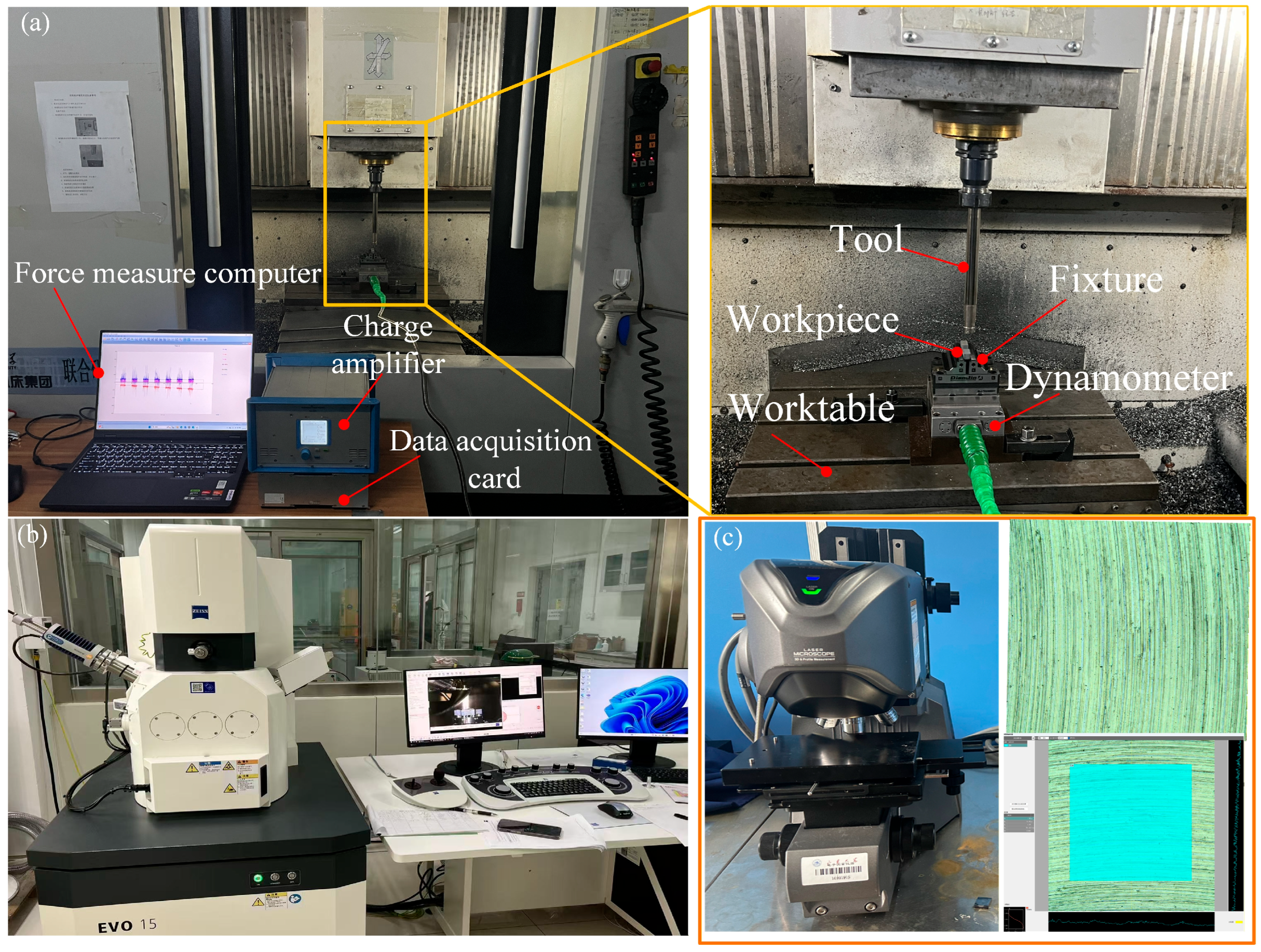
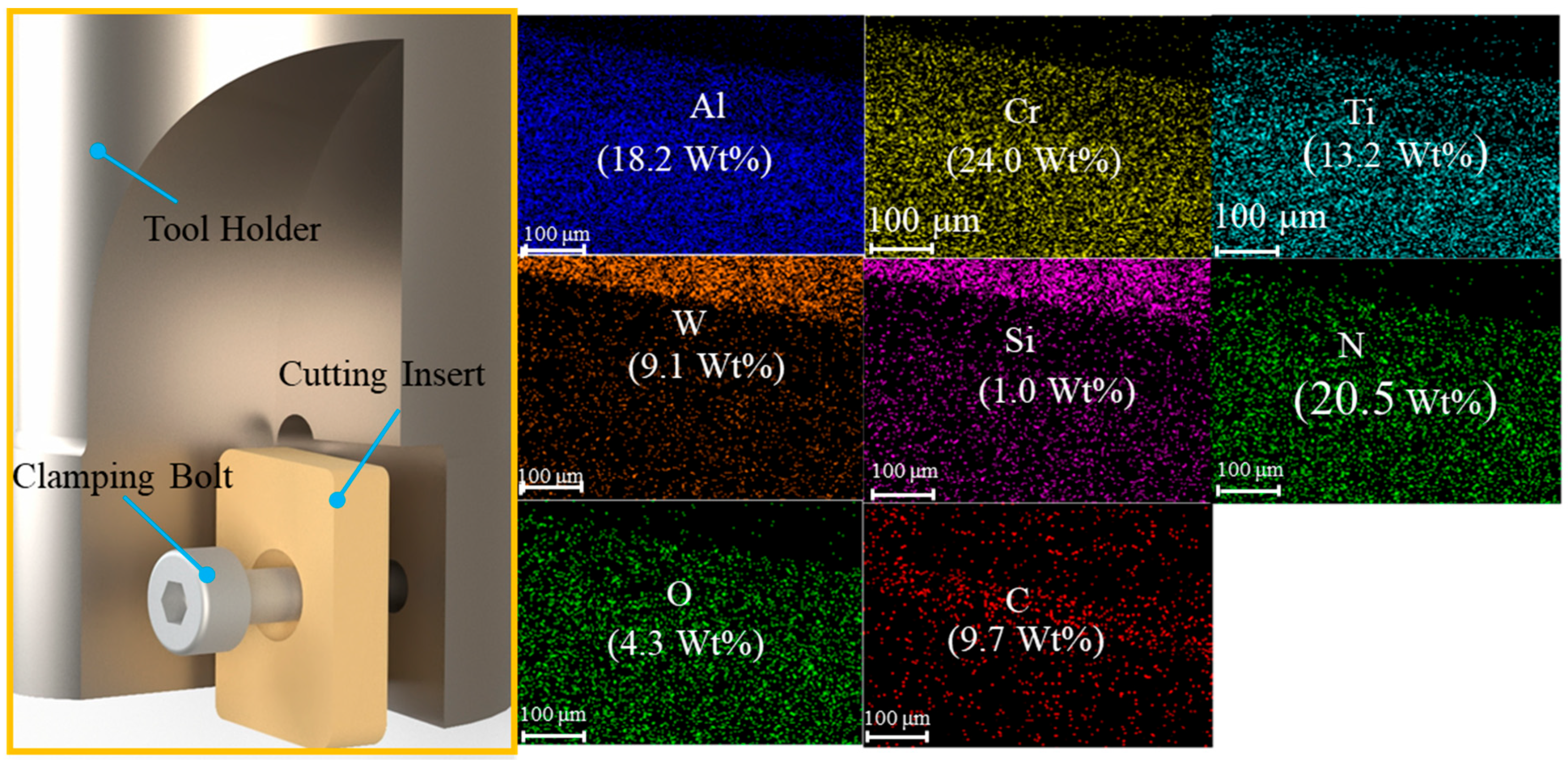
As shown in Figure 1a, the milling experiments were conducted on the Shenyang machine tool (VMC0540d, Shenyang Machine Tool Co., Ltd., Shenyang, China). The workpiece was mounted on the dynamometer (Kistler 9129AA, Kistler Group, Winterthur, Switzerland) using a dedicated fixture, enabling simultaneous acquisition of cutting force signals. A two-flute large overhang cutter with a 20 mm diameter and varying shank lengths was used for milling, with a new tool replaced for each test. This diameter was selected because it represents a commonly used tool size in large overhang milling operations for deep-cavity aerospace components, where the length-to-diameter ratio typically ranges from 3 to 5 [27]. This tool diameter also ensures consistency with our previous studies and ongoing industry collaborations, providing practical relevance to real-world machining scenarios. The physical and mechanical properties of the workpiece material (Ti-6Al-4V) are summarized in Table 1. The chemical compositions of Ti-6Al-4V are listed in Table 2. Figure 2 shows the energy dispersive spectroscopy (EDS) of the cutting insert.

2.2. Experimental Design

A full factorial experimental design was selected to investigate the influences of tool overhang L and feed per tooth fz on the machining performance. The cutting speed vc, axial depth of cut ap, and radial width of cut ae were kept constant, with only the tool overhang L and feed per tooth fz adjusted as variables. The cutting speed of 120 m/min was selected as it falls within the typical recommended range for cemented carbide tools when machining Ti-6Al-4V [7,8]. The three feed per tooth levels (0.03, 0.06, and 0.09 mm/z) were chosen to cover low, medium, and high values, enabling the identification of monotonic trends in machining responses [28]. The overhang lengths (10, 15, and 20 mm) correspond to length-to-diameter ratios of 2, 3, and 4, respectively [4,27], spanning from relatively stable to vibration-prone conditions commonly encountered in deep-cavity machining. The specific milling parameter settings are listed in Table 3. Three repeated experiments were conducted for each combination of process parameters. After milling, the scanning electron microscopy (ZEISS EVO15, Carl Zeiss AG, Oberkochen, Germany) was used to characterize the workpiece surface topography and tool wear area zones, as shown in Figure 1b. Surface roughness values were obtained using a 3D laser confocal microscope (KEYENCE VK-X250), as depicted in Figure 1c. All experiments were carried out under dry machining conditions to clarify the mechanism by which process parameters influence machining performance.

3. Results

3.1. Milling Force Analysis

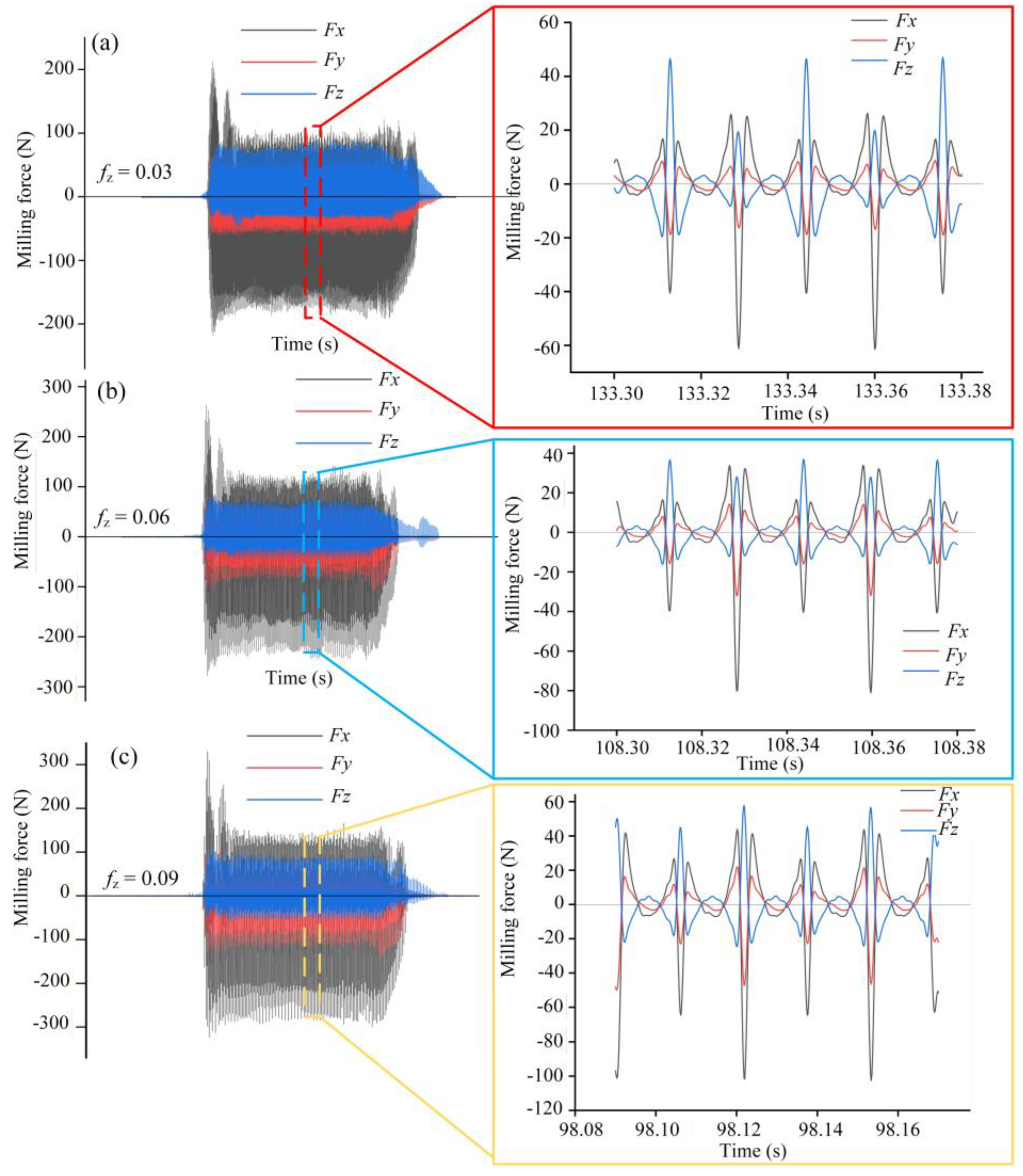
Figure 3 shows the milling force (Fx, Fy, and Fz) measured in three directions at an overhang of 10 mm. The milling force exhibits periodic variations during milling. The cutting force signal displays two distinct peaks within one spindle rotation cycle, consistent with the number of inserts in the milling cutter. Each pulse comprises three processes: cutting-in, steady cutting, and cutting-out, which show the nature of intermittent cutting. The cutting force components in the X, Y, and Z directions show a significant ascending trend as the feed per tooth increases. This trend is theoretically expected because increasing feed per tooth results in a larger uncut chip thickness, which, in turn, increases the material removal rate and the mechanical load on the cutting edge [28]. Consequently, the observed trend aligns well with existing theoretical results, confirming the consistency of the experimental data with fundamental cutting mechanics. The feed force (Fx) and normal force (Fy) show a strong correlation, indicating significant coupling between Fx and Fy during the milling process.
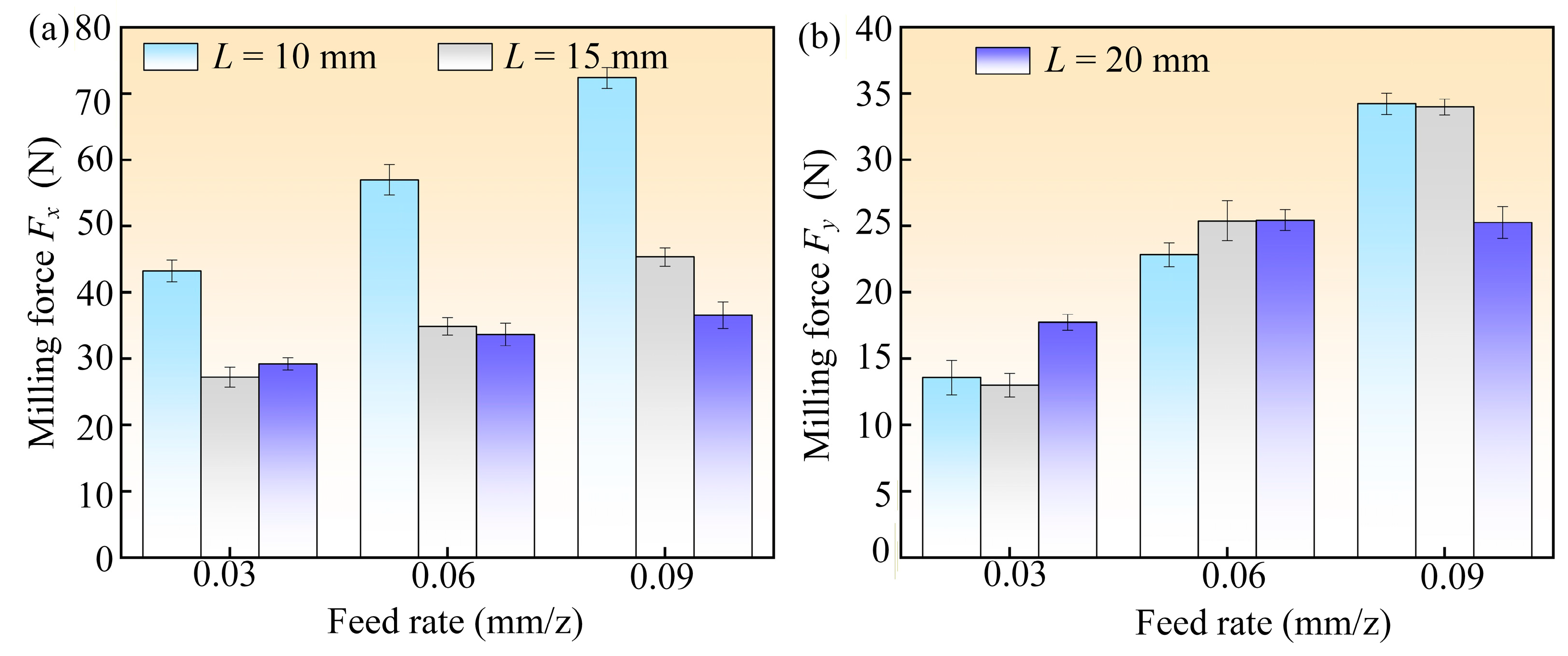
The variations in milling force under various milling parameter conditions are illustrated in Figure 4. The feed force (Fx) is greater than the normal force (Fy) under all experimental conditions. The results are consistent with other milling studies [29]. This phenomenon can be attributed to multiple factors. First, the resistance to material removal and the load on the cutting edge are generally higher in the feed direction than in the normal direction, as the chip thickness variation and the primary cutting action occur predominantly in the feed direction. Second, tool geometry parameters such as helix angle and edge radius contribute to an asymmetric distribution of cutting forces, with a larger component directed along the feed direction. Third, the friction forces on the rake face and flank face are not uniformly distributed, and their resultant effect tends to increase the feed force component. Additionally, the chip flow direction, which is influenced by the tool geometry and cutting conditions, also affects the force distribution among the three directional components. Therefore, the combined effect of these mechanisms results in a consistently higher feed force compared to the normal force in the present milling configuration. The error bars in Figure 4 represent ±1 standard deviation from the mean of three repeated experiments per condition, showing good repeatability of the force measurements across all conditions. The coefficient of variation for the feed force Fx ranged from 3.2% to 8.7% across all parameter combinations.
This attenuated force growth can be explained by a combination of static and dynamic effects. As the nominal feed per tooth increases, the resulting higher cutting force amplifies tool deflection, which, in turn, partially relieves the engagement and limits effective chip thickness growth. This self-limiting mechanism reduces the force sensitivity to feed variations. These momentary losses of cutting action reduce the average material removal rate and further constrain the net increase in mean cutting force with feed. A similar phenomenon was observed by Kuram [23], who reported that longer tool overhangs led to disproportionately smaller force increments due to amplified tool deflection.
The amount of material removed per unit time rises as the feed rate increases, leading to a greater load on the cutting edge and an increase in milling force. Specifically, when the feed per tooth increased from 0.03 mm/z to 0.09 mm/z, the feed force (Fx) increased by approximately 67.34%, 66.74%, and 25.11% for tool overhangs of 10 mm, 15 mm, and 20 mm, respectively. The normal force (Fy) also increased several times. The higher feed rate leads to increased uncut chip thickness, which in turn increases the cutting deformation zone and cutting resistance. Simultaneously, the intensified cutting heat and friction further contribute to the rise in cutting force. It should also be noted that the thermal softening of Ti-6Al-4V at elevated cutting temperatures partially offsets the force increase caused by higher feed rates. Meanwhile, at the largest overhang (L = 20 mm), chatter-induced intermittent cutting reduces the time-averaged heat input, further contributing to the attenuated force growth observed in Figure 4.
Increasing the tool overhang reduces the overall stiffness of the tool holder-tool system, leading to greater elastic deformation and vibration during milling. The vibration not only affects cutting stability but also causes the actual depth of cut to be less than the nominal set values. This phenomenon can cause intermittent contact between the tool and the workpiece, thereby weakening the effective cutting action and resulting in a downward trend in the milling force. When the overhang rises from 10 mm to 20 mm, the feed force (Fx) decreases by approximately 32.4%, 40.91%, and 49.48% at feed rates of 0.03 mm/z, 0.06 mm/z, and 0.09 mm/z, respectively. Reduced system stiffness exacerbates vibration and deformation during cutting, thereby decreasing the actual material removal rate and cutting force.

3.2. Surface Topography

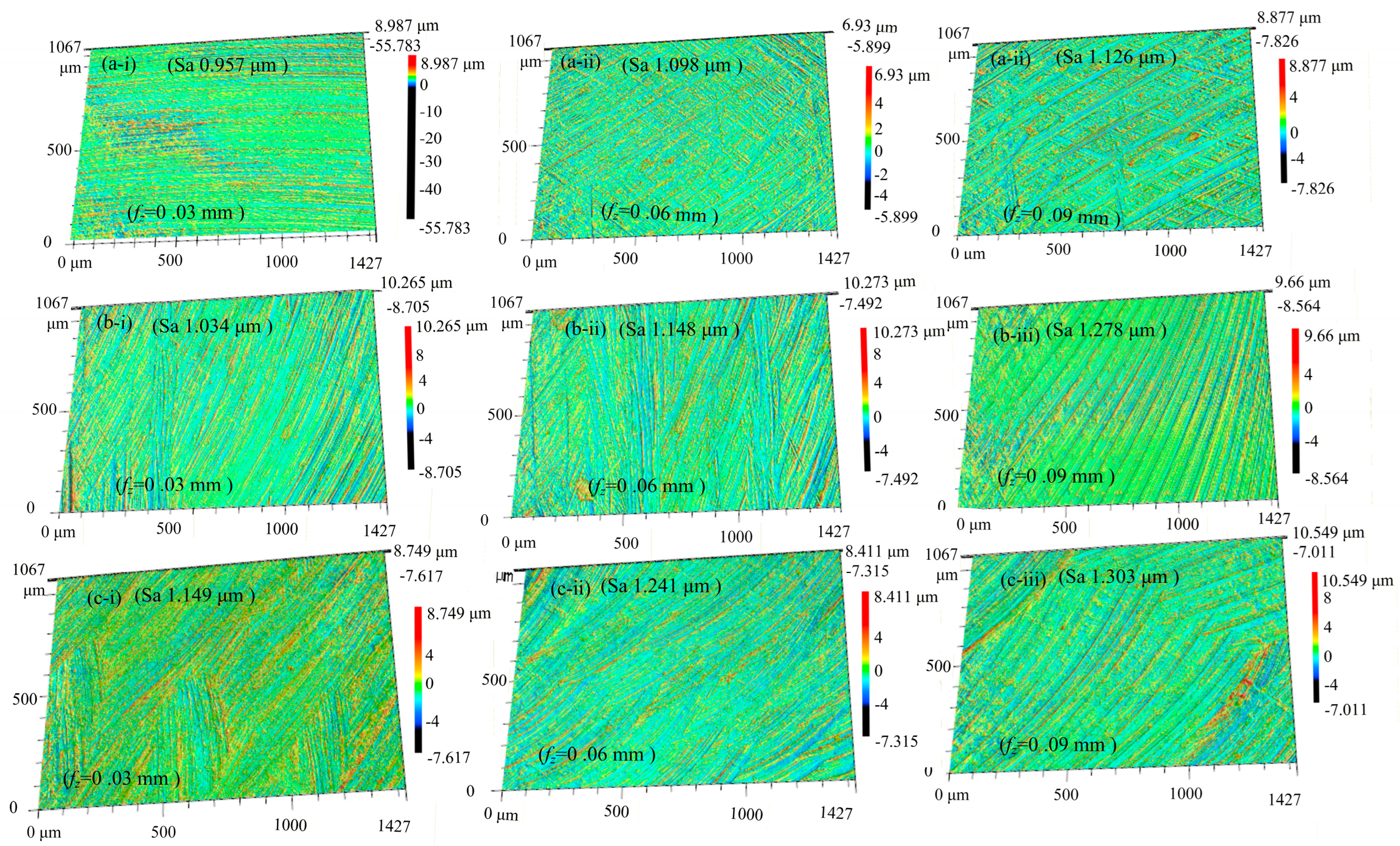
The 3D surface topographies of milling Ti-6Al-4V under different combinations of tool overhang length and feed per tooth are depicted in Figure 5. Although clear tool marks and other micro-defects can be seen in local areas, the surfaces remain intact within the studied parameter range. The overall surface quality is maintained at an acceptable level, indicating that the two-flute flat-end mill used in the experiments can achieve effective machining performance on Ti-6Al-4V under the given conditions. As the tool overhang length increased, the surface quality showed a significant declining trend, characterized by disordered tool marks, intensified vibration marks, and deteriorating surface quality. The trend is primarily attributed to a decrease in tool-system stiffness caused by longer overhang, which leads to more pronounced cutting vibration [30]. The influence of cutting load on surface topography deserves more detailed discussion. As the feed per tooth increases, the cutting load per tooth rises accordingly, leading to multiple effects on the machined surface. First, higher cutting loads intensify plastic side flow of the workpiece material, resulting in smeared surfaces and flattened tool marks in SEM observations. Second, increased cutting loads amplify the dynamic response of the tool system under vibration, resulting in deeper, more irregular vibration-induced marks on the surface. Third, the elevated cutting loads are accompanied by higher cutting temperatures, which promote material adhesion and increase the tendency for surface tearing. These combined effects explain why more severe surface damage, including pronounced tool marks, adhered materials, and tearing defects, is observed under higher feed per tooth conditions in Figure 5. Furthermore, the coupling between overhang and feed per tooth is evident: longer overhang reduces system stiffness, making the cutting process more sensitive to increased cutting loads, thereby further exacerbating surface topography deterioration.
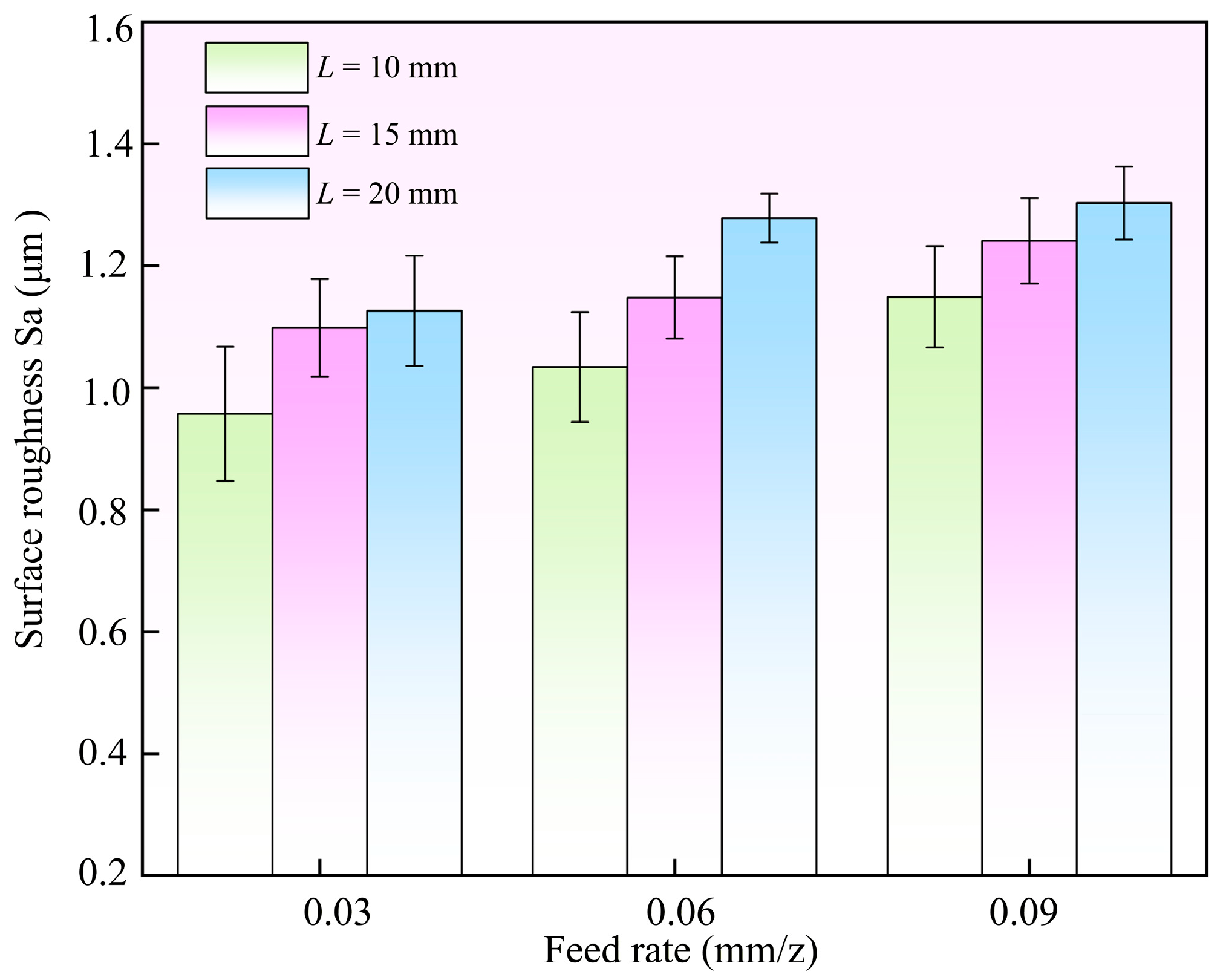
The average surface height (Sa) is a key roughness parameter for evaluating surface quality. Unlike the two-dimensional roughness parameter Ra, which only captures profile variations along a single line, Sa is a three-dimensional areal parameter that provides a more comprehensive description of surface topography by considering the entire measured surface area [15,16]. This is particularly important for large overhang milling, where surface features such as vibration marks, scratches, adhered materials, and plastic side flow are often non-uniformly distributed across the surface. As illustrated in Figure 6, the surface roughness exhibits a regular evolution across various parameter combinations. Both the overhang length and the feed per tooth significantly affect surface roughness. At lower feed per tooth conditions (e.g., 0.03 mm/z), the surface roughness increases with longer overhang length. When the overhang length increases from 10 mm to 20 mm at the feed per tooth of 0.03 mm/z, the surface roughness of the Ti-6Al-4V workpiece increases by approximately 36%. This is mainly attributed to reduced tool system stiffness caused by the increased overhang; vibration occurs more easily under identical cutting parameters, which deteriorates surface quality. The error bars in Figure 6 represent ± one standard deviation from the mean of three repeated measurements per condition, indicating acceptable repeatability of the surface roughness measurements. The coefficient of variation for Sa ranged from 1.8% to 5.4% across all parameter combinations.
The surface roughness also increases with increasing overhang length at a feed per tooth of 0.09 mm/z. This phenomenon may be related to changes in the dynamic characteristics of the cutting process. The shorter overhang lengths are beneficial for maintaining system rigidity and suppressing vibration at low feed rates. Longer cutting tools intensify vibration and increase surface tool marks.
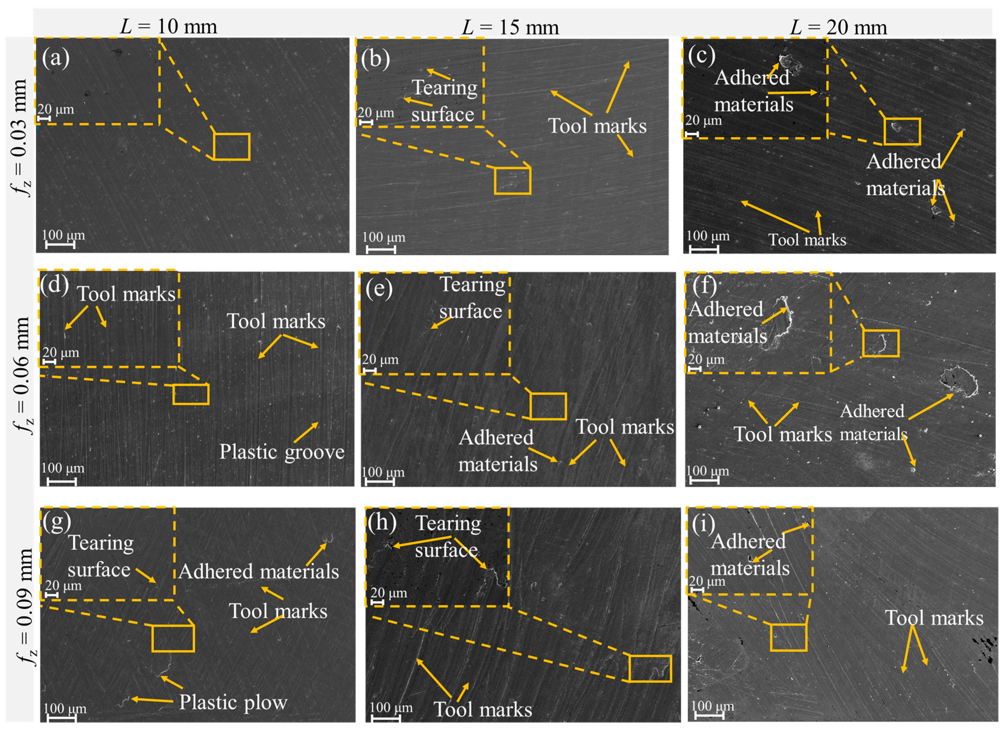
Figure 7 illustrates the surface topography of Ti-6Al-4V milled under different parameters. The SEM analysis reveals that the surface defects mainly consist of cutting marks, tearing surfaces, adhesive materials, and plastic grooves. During normal milling, the primary surface defects on the workpiece are uniformly distributed cutting marks, which result from the kinematic interaction of the cutting edge movement and the feed per tooth. With the same tool overhang, a larger feed per tooth leads to more pronounced tool marks. With the fixed feed per tooth, a larger overhang diminishes system stiffness, thereby amplifying the visibility of the cutting marks. The formation of adhesive layers and surface tearing defects is fundamentally driven by the thermal conditions at the tool–workpiece interface: the low thermal conductivity of Ti-6Al-4V leads to heat accumulation, which promotes atomic diffusion and chemical reactivity, thereby facilitating material adhesion [31]. Therefore, surface deterioration arises from a coupled thermo-mechanical mechanism in which thermal softening and chemical activation drive adhesion and tearing, while dynamic vibration deepens the resulting surface irregularities.
In addition, the workpiece surface exhibits different degrees of adhesive materials under different process parameters. The formation of these adhesive layers is primarily attributed to the thermomechanical conditions during machining. Ti-6Al-4V has high chemical reactivity and low thermal conductivity, leading to elevated temperatures at the tool-chip interface and promoting diffusion and adhesion between the workpiece material and the cutting tool [7,8]. As the feed per tooth increases, the cutting temperature rises due to higher material removal rates and friction, intensifying the adhesion tendency. Similarly, a longer tool overhang reduces system stiffness and exacerbates vibration, causing intermittent contact that can locally increase temperature and pressure, further promoting adhesion. The adhered material is predominantly composed of titanium and aluminum compounds, as confirmed by the EDS analysis shown in the following sections, where elemental transfer from the workpiece to the tool surface is evident. This is mainly because the chips generated during the machining process tend to adhere to the machined surface under high temperature and pressure. If the chips are not removed in time under the tool’s squeezing and friction, an adhesive layer will form on the workpiece surface, significantly reducing surface quality. Due to the physical properties of Ti-6Al-4V, plastic flow is easily generated on the workpiece surface.
Furthermore, surface tearing is a common surface defect when milling Ti-6Al-4V, and its occurrence is closely related to the selection of process parameters. As depicted in Figure 7b,h, the surface tearing area gradually expands as the feed per tooth increases. The tendency for tearing rather than smooth shear separation must be understood in the context of the specific material properties of Ti-6Al-4V. This titanium alloy has a low thermal conductivity (approximately 7.3 W/m·K), leading to significant heat accumulation at the shear zone during machining. The resulting thermal softening reduces the material’s ability to sustain uniform plastic deformation, promoting localized deformation and increasing the likelihood of tear-type failure. Furthermore, Ti-6Al-4V exhibits high chemical reactivity, which promotes adhesion at the tool–chip interface; this adhesion generates fluctuating friction forces that can trigger unstable chip formation and contribute to surface tearing. Increasing the feed per tooth increases the uncut chip thickness, raises the cutting force, and intensifies the associated thermomechanical loads. Under these aggravated conditions, the combination of thermal softening and unstable chip flow makes the material more susceptible to tearing than to clean shear separation. In addition, at low feed rates (fz = 0.03 mm/z), as tool overhang increases, system rigidity decreases, tool marks on the workpiece surface increase, surface quality decreases, and defects such as adhesive material are also present, as shown in Figure 7a–c.

3.3. Chip Morphology

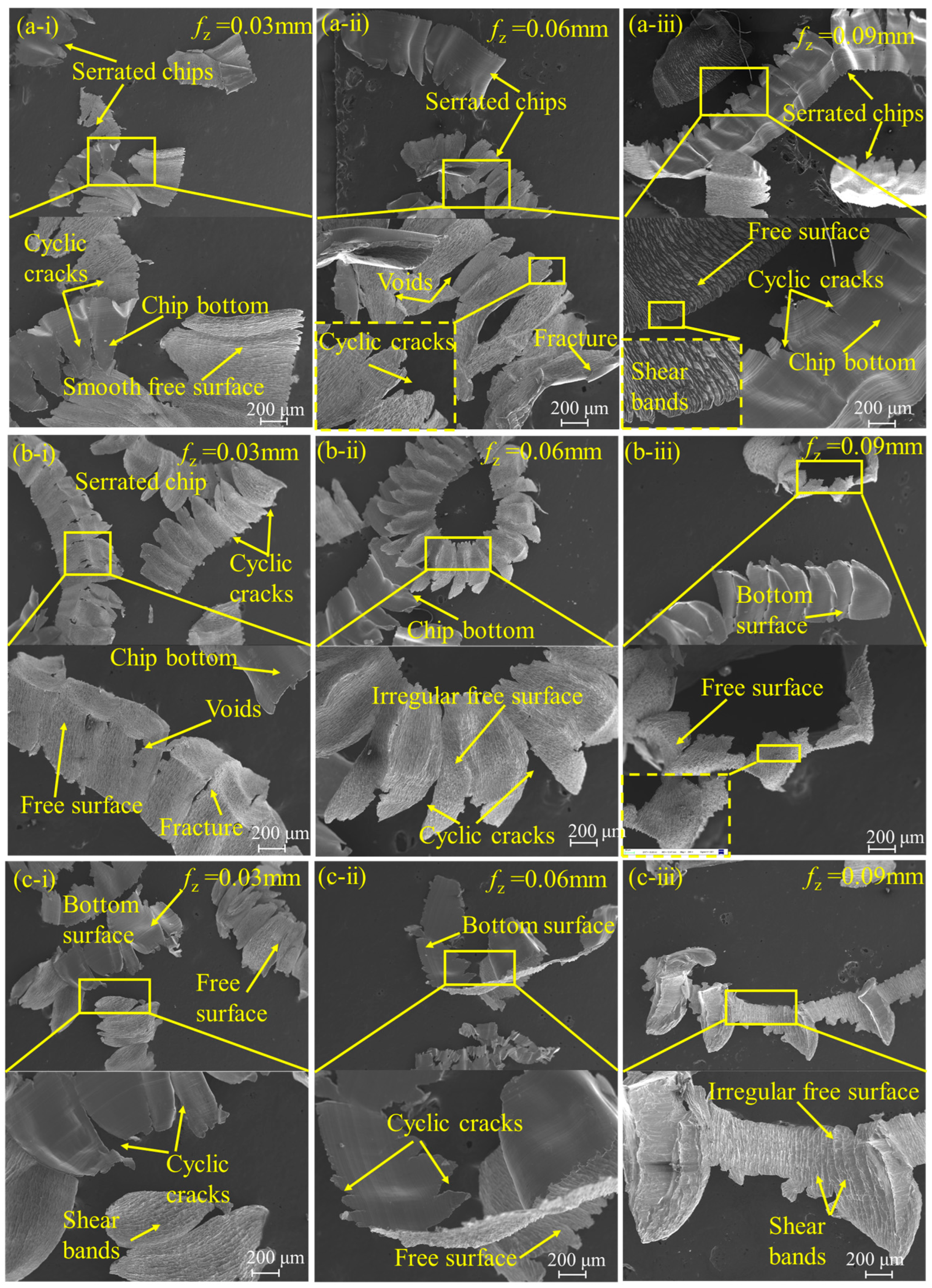
The chip morphology serves as a key indicator of the material-removal process in Ti-6Al-4V alloys. The effective energy consumed in the plowing-dominated and shear-dominated zones significantly impacts chip formation during milling [32]. The chip morphology of Ti-6Al-4V under different milling process parameters is illustrated in Figure 8. The chips exhibit a pronounced serrated structure, with distinct morphological features between the contact surface and the free surface. Indentations left by the cutting edge are visible on the bottom surface, while the free surface exhibits a layered morphology. Under short overhang conditions, the chip-free surface is relatively smooth with a regular contour, as shown in Figure 8(a-i). As the overhang increases, the voids and fractures appear on the free surface (see Figure 8(b-i)). In addition, severe vibration of the long tool holder can cause secondary fractures in the serrated chips, as shown in Figure 8(c-i). The increased overhang reduces the spindle system’s stiffness, leading to chip surface damage.
The degree of segmentation Gs, defined as the ratio of the difference between maximum and minimum chip thickness to the maximum chip thickness, ranged from 0.25 ± 0.02 (L = 20 mm, fz = 0.03 mm/z) to 0.58 ± 0.04 (L = 10 mm, fz = 0.09 mm/z). The segment spacing Ps varied from 34.6 μm to 68.4 μm across all conditions. These values fall within the ranges of Gs = 0.20–0.65 and Ps = 30–80 μm reported in the literature for serrated chip formation in Ti-6Al-4V [33,34]. Quantitatively, Gs increased with feed per tooth across all overhang conditions, from approximately 0.25–0.32 at fz = 0.03 mm/z to approximately 0.51–0.58 at fz = 0.09 mm/z, consistent with the intensified thermo-mechanical loading at larger uncut chip thicknesses. Conversely, increasing the overhang length led to a slight decrease in both Gs and Ps, attributed to reduced effective chip thickness due to tool deflection. Meanwhile, the segmentation frequency increased with overhang, likely driven by the higher vibration frequency under these conditions [35].
Under fixed overhang conditions, lower feed rates result in increasingly unstable chip morphology, indicating that the material-removal mechanism is dominated by plowing. The shear force is insufficient to support sufficient plastic deformation, and the chips are mostly short and thin flakes (see Figure 8(c-i)). However, the chip morphology more closely resembles a shear-dominated process at high feed rates, exhibiting long and stable periodic serrations. The shear band becomes increasingly distinct, especially near the free surface, as shown in Figure 8(a-iii,c-iii). Increasing the feed rate increases cutting force and cutting heat, elevating the strain rate and leading to more pronounced chip serration and clearer shear bands.

3.4. Tool Wear Mechanisms

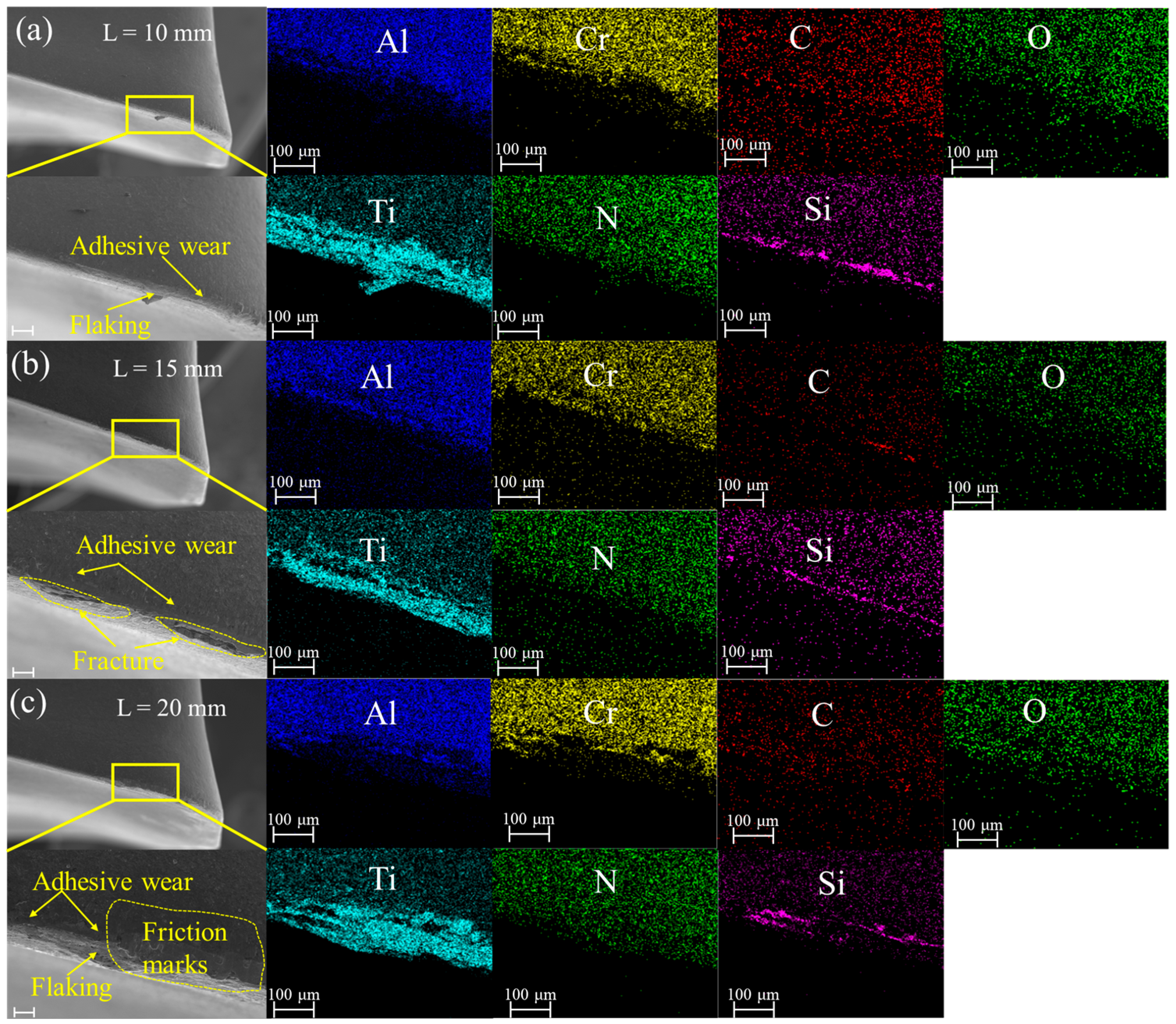
The tool wear is one of the key factors affecting surface quality. To provide additional insight into tool wear development, the VB was measured at three intervals during the cutting process. The final VB value increased from 105.6 µm at the mildest condition (L = 10 mm, fz = 0.03 mm/z) to 292.6 µm at the most aggressive condition (L = 20 mm, fz = 0.09 mm/z), representing an increase of approximately 177%. Figure 9 shows the wear topography and corresponding elemental analysis of the tool flank face at a feed per tooth (fz) of 0.03 mm. Adhesive and abrasive wear can be observed on the flank face. When the tool coating flakes off, the substrate is exposed to the milling environment, forming adhesion layers on its surface, thereby causing wear and element transfer. As shown in Figure 9a, the tool wear area was relatively narrow at an overhang of 10 mm, accompanied by flaking. However, when the overhang increased to 20 mm, the flank wear area expanded significantly, and clear friction marks were visible on the tool surface, exhibiting typical abrasive and adhesive wear, as depicted in Figure 9c. The greater overhang intensified tool vibration, accelerating tool wear. The underlying mechanism by which greater overhang accelerates tool wear deserves further elaboration. Increasing the overhang length reduces the stiffness of the tool-holder system and lowers its natural frequencies, as the effective cantilever length increases. Under the same cutting excitation, a system with reduced stiffness exhibits larger vibration amplitudes, which in turn intensifies the relative motion between the tool and the workpiece. This amplified dynamic interaction leads to several consequences for tool wear. First, alternating contact conditions promote more severe abrasive wear, as fluctuating contact pressure increases the scratching and plowing action on the tool surface. Second, the intensified vibration disrupts the stability of the built-up edge or adhesion layer, causing repeated formation and detachment of the adhered material, which accelerates adhesive wear. Third, increased dynamic loads can promote micro-chipping at the cutting edge, particularly at higher feed rates. Therefore, the observed expansion of the flank wear area and the presence of pronounced friction marks under longer overhang conditions are direct manifestations of the vibration-accelerated wear mechanism. Semi-quantitative EDS analysis of the adhesion layer on the flank face revealed that the Ti content was approximately 48.2 wt% at an overhang of 10 mm, and reached 54.6 wt% at 20 mm. In contrast, the unworn reference area showed no detectable Ti, Al, or V. It consisted predominantly of W (72.5 wt%) and Co (7.8 wt%), confirming that the adhesion layer originates solely from workpiece material transfer.
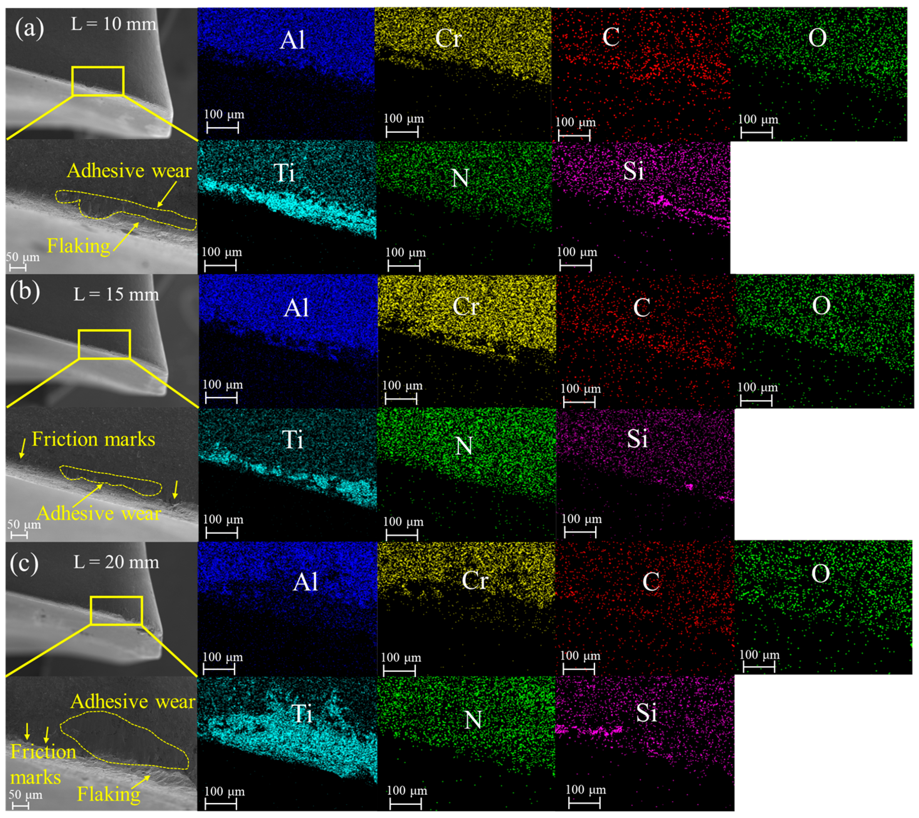
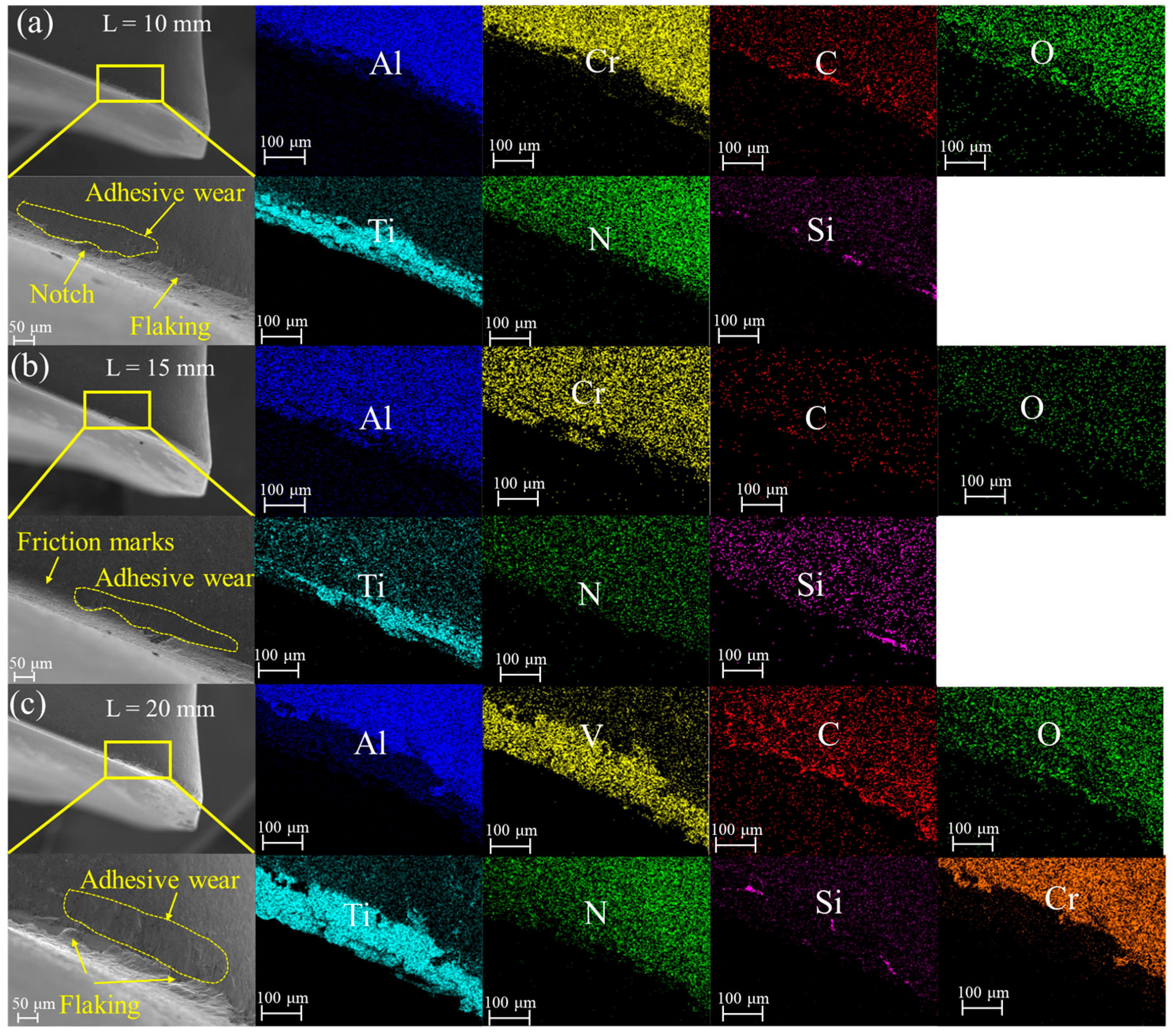
The tool topography and elemental analysis of the tool rake face under the feed per tooth fz of 0.06 mm are illustrated in Figure 10. The wear area on the tool rake face expands as the feed per tooth rises. As shown in Figure 10a, at a tool overhang of 10 mm, the rake face primarily exhibits adhesive wear. When the overhang increases to 20 mm, the rake face wear includes not only adhesive wear but also flaking and friction marks caused by intensified vibration, as depicted in Figure 10c. Figure 11 shows the tool topography and elemental analysis of the tool rake face under the feed per tooth fz of 0.09 mm. The wear area of the cutting tool increases, with both abrasive wear and adhesive wear intensifying. As the feed per tooth increases, the force-heat coupled load on the tool intensifies, significantly accelerating tool wear. Further quantitative EDS data showed that the Ti content in the rake-face adhesion layer increased from 45.8 wt% (L = 10 mm, fz = 0.06 mm/z) to 59.7 wt% (L = 20 mm, fz = 0.09 mm/z), representing a rise of approximately 30%. These trends are consistent with the literature, which shows that cemented carbide tools machining Ti-6Al-4V exhibit Ti-rich adhesion layers as a signature of adhesive wear [36,37].
In addition to dynamic effects, thermal effects play an equally critical role in tool wear: elevated cutting temperatures (up to 800–1000 °C) accelerate atomic diffusion and promote adhesion, which have been identified as the dominant wear mechanisms in cemented carbide tools during Ti-6Al-4V machining [8,36]. The combined thermal and dynamic effects thus create a synergistic wear mechanism, where high temperature drives diffusion and adhesion, while chatter-induced fluctuating stresses cause micro-chipping and coating delamination.

3.5. Dynamic Behavior and Chatter Analysis

To address the dynamic characteristics of the machining system, two complementary approaches were employed: stability lobe diagram (SLD) prediction based on a classic milling dynamics model, and cutting force signal analysis in both time and frequency domains.
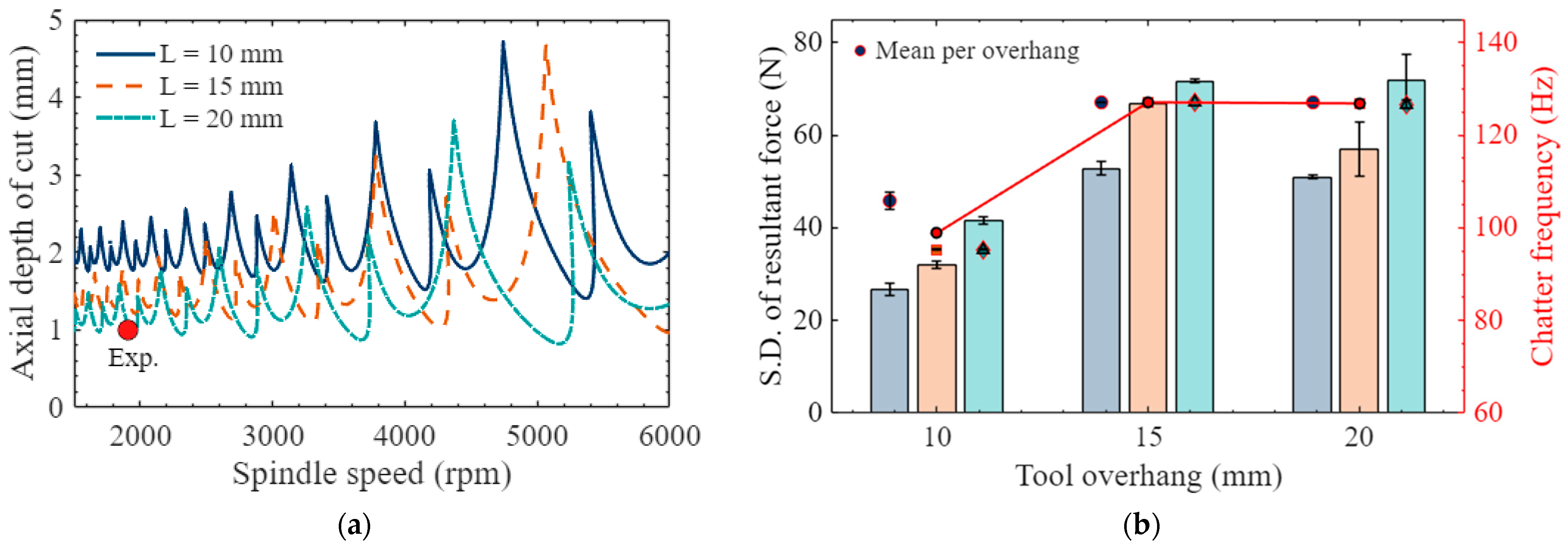
Figure 12a presents the stability lobe diagrams for overhang lengths of 10 mm, 15 mm, and 20 mm milling conditions. The diagrams were calculated using the zero-order frequency domain method [38] with typical cutting force coefficients for Ti-6Al-4V (Kt = 1800 N/mm2, Kr = 600 N/mm2) [39] and estimated tool tip modal parameters (natural frequencies 850, 680, and 520 Hz; damping ratios 0.05, 0.048, and 0.045, respectively) [27,30]. As the overhang increases, the stability lobes shift downward, indicating a marked reduction in the critical axial depth of cut. The experimental point (n = 1910 rpm, ap = 1 mm) lies in the stable region but close to the stability boundary for the 20 mm overhang, confirming that the selected parameters are prone to regenerative chatter. This finding is qualitatively consistent with the conclusion of Kull et al. [40], i.e., a decrease in the static stiffness of the tool system leads to an increase in surface roughness. Meanwhile, Wang et al. [41] also demonstrated that variations in tool overhang alter the tool-point frequency response function (FRF) and, consequently, affect the shape of the SLD. Moreover, chatter instability is known to accelerate tool wear through fluctuating contact stresses that promote adhesive and diffusive mechanisms in coated carbide tools during Ti-6Al-4V machining [36,40,41]. The serrated chip morphology observed in our experiments also aligns with studies showing that dynamic instability modulates segmentation frequency and degree of segmentation [33,34]. Meanwhile, the underlying adiabatic shear band formation is fundamentally linked to the thermal properties of Ti-6Al-4V and further influenced by vibration [35].
It should be noted that the modal parameters used in the SLD calculation (natural frequencies of 850, 680, and 520 Hz and damping ratios of 0.05, 0.048, and 0.045 for overhang lengths of 10, 15, and 20 mm, respectively) were estimated based on typical values reported in the literature for similar tool-holder-spindle configurations [27,30], rather than experimentally measured via impact hammer testing. As such, the stability lobe diagrams presented in Figure 12a should be interpreted as qualitative indicators of the stability trends under varying overhang conditions, rather than exact quantitative predictions of the critical depth of cut. The observed downward shift of the stability lobes with increasing overhang is consistent with the expected reduction in dynamic stiffness. It qualitatively supports the experimental finding that the 20 mm overhang condition is more prone to chatter.
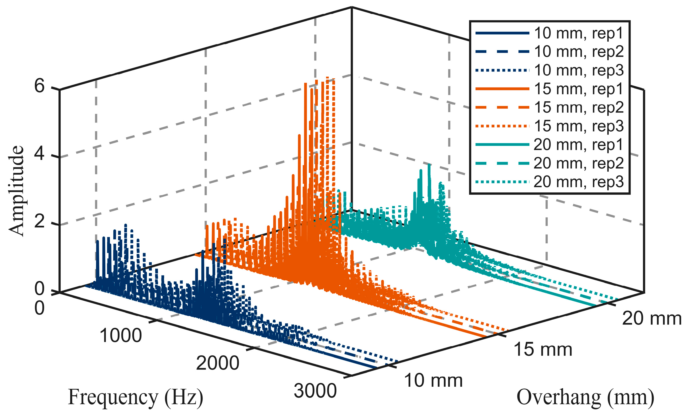
Figure 12b shows the power spectra of the Fx for overhang lengths of 10 mm and 20 mm at a cutting speed of 120 m/min by fast Fourier transform (FFT). The spindle rotation frequency (approximately 31.8 Hz for 1910 rpm) and its harmonics are indicated, with the chatter frequency at approximately 127 Hz marked for the 20 mm overhang condition. A detailed comparison of stability lobes and force-frequency spectra for different overhang lengths is provided in Figure A1 (Appendix A). For the 10 mm overhang, the spectrum is dominated by the spindle rotation frequency (31.8 Hz) and its harmonics, with no significant non-rotational components. In contrast, the 20 mm overhang exhibits a prominent peak at approximately 127 Hz, which is not an integer multiple of the rotation frequency. This frequency is attributed to the first bending mode of the tool-holder-spindle system. Its emergence coincides with the increased vibration intensity and deteriorated surface quality observed in the longer overhang condition. To quantify vibration intensity, the RMS values of the fluctuating force components were calculated. The RMS value in the X-direction increased from 18.5 N at L = 10 mm to 48.5 N at L = 20 mm (both at fz = 0.09 mm/z), consistent with the emergence of a strong chatter peak at approximately 127 Hz in the FFT spectrum (Figure 12b).
Table 4 qualitatively compares key machining indicators between short (10 mm) and long (20 mm) overhangs. The feed force decreases with overhang due to the tool deflection effect, while chip morphology changes from continuous bands to fractured pieces, and surface topography develops from regular tool marks to severe tearing and waviness. These observations are fully consistent with reduced dynamic stiffness and the onset of chatter at approximately 127 Hz, confirming that the degradation of surface quality and accelerated tool wear are primarily caused by the unstable dynamic behavior of the system under large overhang conditions.

3.6. Empirical Prediction Models

To enable quantitative prediction of the feed force Fx and surface roughness Sa within the investigated parameter range, two types of empirical models were developed based on the experimental data: a conventional power-law model and a second-order response surface model (RSM). The empirical models developed in this section use the tool overhang length L (input variable with levels 10, 15, and 20 mm) and the feed per tooth fz (input variable with levels 0.03, 0.06, and 0.09 mm/z) as predictors. All other cutting parameters were kept constant at the values listed in Table 3. Therefore, Table 3 itself serves as the summary of the modeling scope and experimental conditions.

3.6.1. Power Law Model

The power-law model follows the general form:
Y = k · L a · f z b
where Y is either Fx or Sa. The coefficients were determined by logarithmic transformation and linear regression. The resulting equations are as follows:
F x = 882.30 · L 0.8137 · f z 0.3238 S a = 0.8632 · L 0.2583 · f z 0.1454
The negative exponent of L in the Fx model reflects the reduction in cutting force with increasing overhang due to decreased system stiffness. The positive exponents in the Sa model indicate that both a longer overhang and a larger feed per tooth deteriorate surface quality.

3.6.2. Response Surface Models

To improve predictive accuracy, second-order polynomial response surface models were constructed, including linear terms, interaction, and quadratic terms:
Y = β 0 + β 1 L + β 2 f z + β 3 L · f z + β 4 L 2 + β 5 f z 2
The coefficients obtained by multiple linear regression are listed in Table 5.

3.6.3. Model Performance Comparison

The predictive capability of the two models was evaluated using the coefficient of determination R2, the mean absolute percentage error (MAPE), and the maximum absolute percentage error (Max APE). The results are summarized in Table 6.
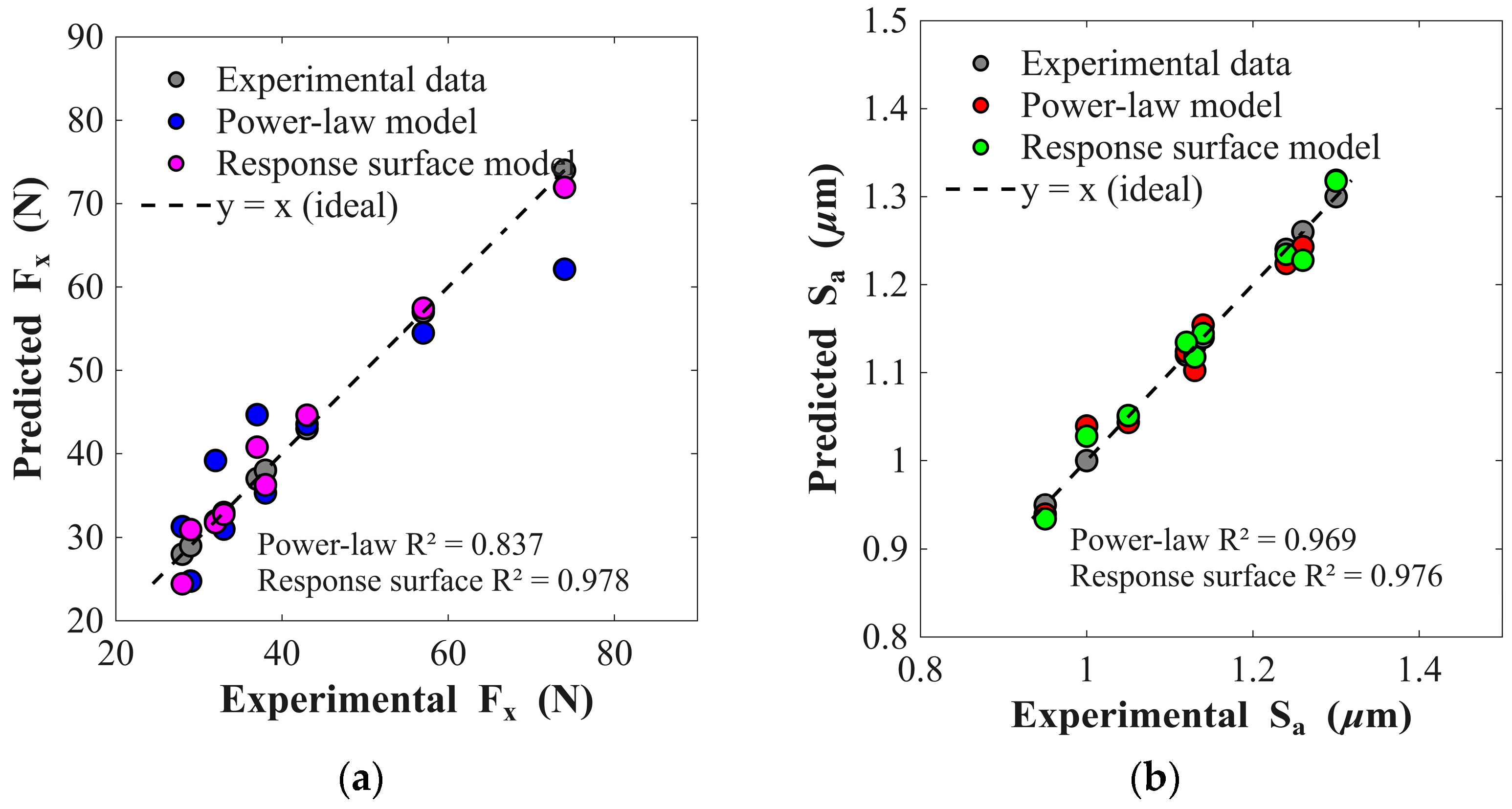
The response surface model significantly outperforms the power-law model for Fx, raising R2 from 0.84 to 0.98 and reducing the MAPE from 11.6% to 4.8%. For Sa, both models are highly accurate, with the RSM giving a marginal improvement.
Figure 13 shows the scatter plots of experimental values against the predictions of the two models, together with the ideal diagonal line y = x. The points of the response surface model lie closer to the diagonal than those of the power-law model, especially for the feed force. The R2 values are also displayed in the figure. These results demonstrate that the response surface model provides a simple yet reliable tool for predicting cutting force and surface quality in large-overhang milling of Ti-6Al-4V under the investigated conditions.
It should be noted that the empirical models established above are strictly valid only within the investigated parameter range, i.e., overhang length L from 10 to 20 mm and feed per tooth fz from 0.03 to 0.09 mm/z.

4. Conclusions

In this study, the mechanisms of tool wear and machinability were investigated during large overhang milling with different tool shank lengths. The key conclusions are as follows:
(1)
The milling forces exhibited significant variations under different overhang lengths and feed rates. Cutting forces increase significantly with higher feed rates and decrease as the overhang length increases. When the feed per tooth increases from 0.03 mm/z to 0.09 mm/z, the feed force (Fx) rises by approximately 67.34%, 66.74%, and 25.11%, respectively. When the overhang increases from 10 mm to 20 mm, the Fx decreases by approximately 32.4%, 40.91%, and 49.48%, respectively.
(2)
The surface quality indicators are closely related to tool overhang and feed per tooth. Increasing the feed rate leads to a deterioration in surface roughness, manifested as obvious feed marks, plastic plow, and localized tearing. Increasing the overhang reduces tool stiffness and increases vibration, exacerbating tool marks on the workpiece surface.
(3)
The chip morphology during milling of Ti-6Al-4V primarily exhibits serrated chips, involving porosity, cyclic cracking, and fracture. At low feed rates, serration is less pronounced, and chips remain relatively continuous. The shear bands appear on the surface as the feed rate increases. The large overhangs increase the vibration, exacerbating chip fracture.
(4)
Tool wear analysis indicates that the primary forms of tool wear include adhesive wear and abrasive wear after milling, manifested as flaking, adhesive materials, and friction marks. As the feed rate increases, tool wear intensifies. Increased overhang exacerbates surface friction on the tool.
(5)
Based on the stability lobe diagram and the cutting force frequency spectrum analysis, it was found that when the overhang is ≥15 mm, the system exhibits chatter at about 127 Hz, which is the main reason for the decline in surface quality.
(6)
Within the investigated parameter range, the combination of L = 10 mm and fz = 0.06 mm/z offers the best balance between machining efficiency and surface quality. Meanwhile, for longer overhangs, a reduced feed of fz = 0.03 mm/z is recommended.
Based on the findings of this study, several directions for future work are proposed. First, real-time monitoring of vibration signals should be integrated to establish a direct quantitative correlation between tool overhang, dynamic stability, and resulting surface quality. Second, quantitative modeling of tool wear evolution under varying overhang and feed conditions is needed to enable predictive tool life management in industrial applications. Third, the performance of advanced coated tools, such as those with AlTiN or multilayer coatings, should be evaluated under large overhang milling conditions to assess their potential for improving wear resistance.

Author Contributions

Conceptualization, F.G., S.Z. and H.Y.; methodology, F.G., A.J., H.Y., X.L. and Z.L.; validation, A.J. and T.W.; data curation, Y.W.; investigation, Y.W. and T.W.; writing—original draft, F.G. and A.J.; writing—review and editing, S.Z.; supervision, F.G., X.L. and Z.L.; funding acquisition, X.L. and Z.L. All authors have read and agreed to the published version of the manuscript.

Funding

This research was funded by National Natural Science Foundation of China (No. 52405499), Shandong Provincial Natural Science Foundation (ZR2024QE177), Shandong Provincial Natural Science Foundation for Excellent Young Scientists Fund Program (Overseas) (No. 2025HWYQ-004), Young Taishan Scholars Program of Shandong Province (No. tsqn202312073), Tribology Science Fund of the State Key Laboratory of Tribology in Advanced Equipment (SKLTKF24B01), Shandong Postdoctoral Science Foundation (SDZZ-ZR-202501282), and the financial support from Outstanding Young and Middle-aged Scholars of Shandong University.

Data Availability Statement

Data will be made available on request.

Conflicts of Interest

Aisheng Jiang and Yuzhong Wang were employed by the company Zhuzhou Cemented Carbide Group Corp. Ltd., and the company Zhuzhou Cemented Carbide Cutting Tools Co., Ltd. The remaining authors declare that the research was conducted in the absence of any commercial or financial relationships that could be construed as a potential conflict of interest.

Appendix A

Figure A1 presents stability lobe diagrams for three overhang lengths (10, 15, and 20 mm) and the corresponding Fx force spectra at 120 m/min.
Figure A1. Three-dimensional waterfall plot of Fx cutting force spectra at a cutting speed of 120 m/min for overhang lengths of 10 mm, 15 mm, and 20 mm. Each overhang condition includes three repeated experiments (solid, dashed, and dotted lines).
Jmmp 10 00162 g0a1

References

  1. Aslantas, K.; Hasçelik, A.; Erçetin, A.; Danish, M.; Alatrushi, L.K.H.; Rubaiee, S.; Mahfouz, A.B. Effect of cutting conditions on tool wear and wear mechanism in micro-milling of additively manufactured titanium alloy. Tribol. Int. 2024, 193, 109340. [Google Scholar] [CrossRef]
  2. Mavros, N.; Larimian, T.; Esqivel, J.; Gupta, R.K.; Contieri, R.; Borkar, T. Spark plasma sintering of low modulus titanium-niobium-tantalum-zirconium (TNTZ) alloy for biomedical applications. Mater. Des. 2019, 183, 108163. [Google Scholar] [CrossRef]
  3. Rajhi, W.; Boujelbene, M.; Said, L.B.; El Aoud, B.; Alshammrei, S. Modeling the surface alterations effect on EDM efficiency of Ti6Al4V alloy. Int. J. Refract. Met. Hard Mat. 2025, 132, 107292. [Google Scholar] [CrossRef]
  4. Lindvall, R.; Gayubo, J.C.; Gutnichenko, O.; Auzenat, F.O.; M’Saoubi, R.; Bushlya, V. Performance and wear mechanisms of TiAlN-NbN coated cemented carbide in milling Ti6Al4V with different cooling and lubrication approaches. Wear 2025, 571, 205846. [Google Scholar] [CrossRef]
  5. De Rojas Candela, C.S.; Riquelme, A.; Rams, J.; Torres, B.; Rodrigo, P. Effect of laser-directed energy deposition additive manufacturing parameters on the wear behavior of Ti6Al4V/SiCp composites. Int. J. Refract. Met. Hard Mat. 2026, 136, 107577. [Google Scholar] [CrossRef]
  6. Terlicka, S.; Janus, K.; Sobczak, N.; Sobczak, J.J. Comparative study of high-temperature interaction of Nb, TiNb, and Ti substrates with liquid Mg. Int. J. Refract. Met. Hard Mat. 2025, 132, 107245. [Google Scholar] [CrossRef]
  7. Sharma, P.; Mishra, S.K.; Ramkumar, J. Damage mechanisms and wear progression of advanced AlTiSiN coatings deposited on WC/Co cemented carbide cutting tools for machining under cryogenic conditions. Ceram. Int. 2025, 51, 54530–54548. [Google Scholar] [CrossRef]
  8. Hu, W.; Du, P.; Qiu, X.; Zhao, X.; Hu, Z.; Zhang, J.; Liu, Y. Enhanced dry machinability of TC4 titanium alloy by longitudinal bending hybrid ultrasonic vibration-assisted milling. J. Clean. Prod. 2022, 379, 134866. [Google Scholar] [CrossRef]
  9. Zha, X.; Qin, H.; Yuan, Z.; Xi, L.; Zhang, T.; Jiang, F. Effect of cutting feed rate on machining performance and surface integrity in cutting process of Ti-6Al-4V alloy. Int. J. Adv. Manuf. Technol. 2024, 131, 2791–2809. [Google Scholar] [CrossRef]
  10. Xia, Y.; Wan, Y.; Luo, X.; Wang, H.; Gong, N.; Cao, J.; Song, Q.; Liu, Z. Chatter suppression in large overhang face milling using a toolholder with high dynamic performance. Int. J. Adv. Manuf. Technol. 2020, 108, 1713–1724. [Google Scholar] [CrossRef]
  11. Quintana, G.; Ciurana, J. Chatter in machining processes: A review. Int. J. Mach. Tools Manuf. 2011, 51, 363–376. [Google Scholar] [CrossRef]
  12. Deng, C.; Ding, H.; Miao, J.; Tan, F. Co-Kriging model-based multi-fidelity regression for refining milling stability pre-dictions of variable tool overhang length using limited experimental data. Int. J. Prod. Res. 2025, 63, 2577–2598. [Google Scholar] [CrossRef]
  13. Mishra, V.; Khan, G.S.; Chattopadhyay, K.D.; Nand, K.; Sarepaka, R.V. Effects of tool overhang on selection of machining parameters and surface finish during diamond turning. Measurement 2014, 55, 353–361. [Google Scholar] [CrossRef]
  14. Wojciechowski, S.; Wiackiewicz, M.; Krolczyk, G.M. Study on metrological relations between instant tool displacements and surface roughness during precise ball end milling. Measurement 2018, 129, 686–694. [Google Scholar] [CrossRef]
  15. Jamil, M.; He, N.; Zhao, W.; Khan, A.M.; Xiang, H.; Gupta, M.K.; Iqbal, A. A novel low-pressure hybrid dry ice blasting system for improving the tribological and machining characteristics of AISI-52100 tool steel. J. Manuf. Process. 2022, 80, 152–160. [Google Scholar] [CrossRef]
  16. Voss, R.; Seeholzer, L.; Kuster, F.; Wegener, K. Influence of fiber orientation, tool geometry and process parameters on surface quality in milling of CFRP. CIRP J. Manuf. Sci. Technol. 2017, 18, 75–91. [Google Scholar] [CrossRef]
  17. Liu, D.; Li, C.; Dong, L.; Qin, A.; Zhang, Y.; Yang, M.; Gao, T.; Wang, X.; Liu, M.; Cui, X.; et al. Kinematics and improved surface roughness model in milling. Int. J. Adv. Manuf. Technol. 2024, 131, 2087–2108. [Google Scholar] [CrossRef]
  18. Zhang, P.; Wang, S.; Zhang, J.; Sun, Y.; Zhou, H.; Yue, X. Research on high speed machining mechanism and tool wear mechanism of nickel-based superalloy 718. Vacuum 2024, 229, 113538. [Google Scholar] [CrossRef]
  19. Wu, X.; Chen, Z.; Ke, W.; Jiang, F.; Zhao, M.; Li, L.; Shen, J.; Zhu, L. Investigation on surface quality in micro milling of additive manufactured Ti6Al4V titanium alloy. J. Manuf. Process. 2023, 101, 446–457. [Google Scholar] [CrossRef]
  20. Zhu, S.; Fu, G.; Zheng, Y.; Lu, C.; Wang, X.; Wang, T.; Fu, J. Free-form surface texture morphology modeling in five-axis ball-end milling considering effective cutting edge. Thin-Walled Struct. 2025, 215, 113506. [Google Scholar] [CrossRef]
  21. Güven, S.; Gökkaya, H.; Sur, G.K.; Motorcu, A.R. Effects of cutting parameters on tool wear in milling Inconel 625 superalloys with a SiAlON ceramic and the prediction of tool life. Ceram. Int. 2025, 51, 5646–5658. [Google Scholar] [CrossRef]
  22. Gao, G.; Xia, Z.; Su, T.; Xiang, D.; Zhao, B. Cutting force model of longitudinal-torsional ultrasonic-assisted milling Ti-6Al-4V based on tool flank wear. J. Mater. Process. Technol. 2021, 291, 117042. [Google Scholar] [CrossRef]
  23. Kuram, E. Overhang length effect during micro-milling of Inconel 718 superalloy. J. Braz. Soc. Mech. Sci. Eng. 2019, 41, 166. [Google Scholar] [CrossRef]
  24. Neto, H.K.; Diniz, A.E.; Pederiva, R. Influence of tooth passing frequency, feed direction, and tool overhang on the surface roughness of curved surfaces of hardened steel. Int. J. Adv. Manuf. Technol. 2015, 82, 753–764. [Google Scholar] [CrossRef]
  25. Kiyak, M.; Kaner, B.; Sahin, I.; Aldemir, B.; Cakir, O. The dependence of tool overhang on surface quality and tool wear in the turning process. Int. J. Adv. Manuf. Technol. 2010, 51, 431–438. [Google Scholar] [CrossRef]
  26. Allenov, D.G.; Borisovna, K.D.; Ghorbani, S.; Kashyzadeh, K.R. Simultaneous effects of cutting depth and tool overhang on the vibration behavior of cutting tool and high-cycle fatigue behavior of product: Experimental re-search on the turning machine. Int. J. Adv. Manuf. Technol. 2022, 122, 2361–2378. [Google Scholar] [CrossRef]
  27. Meng, F.; Song, Q.; Peng, Y.; Liu, Z. Influence of unilateral constraint on machining dynamics of large overhang milling cutter. Int. J. Adv. Manuf. Technol. 2023, 125, 3577–3591. [Google Scholar] [CrossRef]
  28. Lin, Y.C.; Wu, K.D.; Shih, W.C.; Hung, J.P. Evaluation of the Optimum Machining Stability of a Milling Tool with Different Flutes and Overhangs. Adv. Sci. Technol. Res. J. 2019, 13, 56–64. [Google Scholar] [CrossRef]
  29. Liang, X.; Wang, C.; Zhang, C.; Cheung, C.F. Physical-metallurgical properties and micro-milling machinability evaluation of high entropy alloy FeCoNiCrAlx. J. Mater. Res. Technol. 2022, 21, 3285–3300. [Google Scholar] [CrossRef]
  30. Ji, Y.; Liu, R. Research on the influence of cutter overhang length on robotic milling chatter stability. Sci. Rep. 2024, 14, 24838. [Google Scholar] [CrossRef]
  31. Nouari, M.; Makich, H. Experimental study on tool wear when machining super titanium alloys: Ti6Al4V and Ti-555. Int. J. Adv. Manuf. Technol. 2017, 92, 3557–3568. [Google Scholar] [CrossRef]
  32. Bolar, G.; Adhikari, R.; Nayak, S.N.; Joshi, S.N. Assessment of ignition risk in dry helical hole milling of AZ31 magnesium alloy considering the machining temperature and chip morphology. J. Manuf. Process. 2022, 77, 260–271. [Google Scholar] [CrossRef]
  33. Zhu, L.; Wu, J.; Li, Z.; Liu, C. Investigating chip morphology and its characteristics in the high-speed milling of a Ti-6Al-4V thin plate. J. Mech. Sci. Technol. 2015, 29, 4359–4366. [Google Scholar] [CrossRef]
  34. Yang, Q.; Wu, Y.; Liu, D.; Chen, L.; Lou, D.; Zhai, Z.; Liu, Z. Characteristics of serrated chip formation in high-speed machining of metallic materials. Int. J. Adv. Manuf. Technol. 2016, 86, 1201–1206. [Google Scholar] [CrossRef]
  35. Zang, J.; Zhao, J.; Li, A.; Pang, J. Serrated chip formation mechanism analysis for machining of titanium alloy Ti-6Al-4V based on thermal property. Int. J. Adv. Manuf. Technol. 2018, 98, 119–130. [Google Scholar] [CrossRef]
  36. Lindvall, R.; Bermejo, J.M.B.; Bjerke, A.; Andersson, J.M.; Vikenadler, E.; M’Saoubi, R.; Bushlya, V. On the wear mechanisms of uncoated and coated carbide tools in milling titanium alloys. Int. J. Refract. Met. Hard Mat. 2024, 124, 106846. [Google Scholar] [CrossRef]
  37. Hrechuk, A.; Bushlya, V.; Ståhl, J.E. Performance and wear mechanisms of uncoated cemented carbide cutting tools in Ti6Al4V machining. Wear 2021, 477, 203884. [Google Scholar]
  38. Altintas, Y.; Budak, E. Analytical prediction of stability lobes in milling. CIRP Ann.—Manuf. Technol. 1995, 44, 357–362. [Google Scholar] [CrossRef]
  39. Dang, J.; Zhang, H.; Ming, W.; An, Q. An efficient method for determining the cutting force coefficients in milling a titanium alloy. Int. J. Adv. Manuf. Technol. 2023, 126, 1633–1643. [Google Scholar]
  40. Kull, H.N.; Diniz, A.E.; Pederiva, R. Correlating tool life and workpiece surface roughness with tool stiffness in the milling of Ti-6Al-4V alloy with toroidal tool. Int. J. Adv. Manuf. Technol. 2014, 75, 139–152. [Google Scholar] [CrossRef]
  41. Wang, D.; Wang, X.; Liu, Z.; Gao, P.; Ji, Y.; Löser, M.; Ihlenfeldt, S. Surface location error prediction and stability analysis of micro-milling with variation of tool overhang length. Int. J. Adv. Manuf. Technol. 2018, 99, 919–936. [Google Scholar] [CrossRef]
Figure 1. Experimental setup. (a) Milling Ti-6Al-4V. (b) Surface topography Characterization. (c) Surface roughness measurement.
Jmmp 10 00162 g001
Figure 2. EDS analysis of the cutting insert (type: APMT1135PDTR; substrate: CY3350) performed by the authors prior to the milling experiments to characterize the elemental composition of the tool used in this work. This figure represents an original characterization result.
Jmmp 10 00162 g002
Figure 3. Cutting force in three directions with an overhang of 10 mm. (a) Feed per tooth fz (mm/z) = 0.03 (b) Feed per tooth fz (mm/z) = 0.06 (c) Feed per tooth fz (mm/z) = 0.09.
Jmmp 10 00162 g003
Figure 4. Cutting force under different feed-per-tooth conditions. (a) Milling force Fx. (b) Milling force Fy. The error bars on each bar chart represent ± one standard deviation from the mean of three repeated experiments per condition.
Jmmp 10 00162 g004
Figure 5. Surface morphology under different conditions. (a) Overhang lengths of 10 mm. (b) Overhang lengths of 15 mm. (c) Overhang lengths of 20 mm.
Jmmp 10 00162 g005
Figure 6. Surface roughness under different conditions. The error bars on each bar chart represent ± one standard deviation from the mean of three repeated measurements per condition.
Jmmp 10 00162 g006
Figure 7. Machined surface after the milling process under different parameters. Subfigures (ai) correspond to fz (mm/z)/L (mm): (a) 0.03/10; (b) 0.03/15; (c) 0.03/20; (d) 0.06/10; (e) 0.06/15; (f) 0.06/20; (g) 0.09/10; (h) 0.09/15; (i) 0.09/20.
Jmmp 10 00162 g007
Figure 8. Chip morphology under different conditions. (a) Overhang lengths of 10 mm. (b) Overhang lengths of 15 mm. (c) Overhang lengths of 20 mm.
Jmmp 10 00162 g008
Figure 9. Tool wear under the fz of 0.03 mm. (a) Overhang lengths of 10 mm. (b) Overhang lengths of 15 mm. (c) Overhang lengths of 20 mm.
Jmmp 10 00162 g009
Figure 10. Tool wear under the fz of 0.06 mm. (a) Overhang lengths of 10 mm. (b) Overhang lengths of 15 mm. (c) Overhang lengths of 20 mm.
Jmmp 10 00162 g010
Figure 11. Tool wear under the fz of 0.09 mm. (a) Overhang lengths of 10 mm. (b) Overhang lengths of 15 mm. (c) Overhang lengths of 20 mm.
Jmmp 10 00162 g011
Figure 12. Dynamic behavior and chatter analysis. (a) Stability lobe diagrams for overhang lengths of 10 mm, 15 mm, and 20 mm. The diagrams were calculated using the zero-order frequency domain method [38] with typical cutting force coefficients for Ti-6Al-4V (Kt = 1800 N/mm2, Kr = 600 N/mm2) [39] and estimated tool tip modal parameters (natural frequencies 850, 680, and 520 Hz; damping ratios 0.05, 0.048, and 0.045, respectively) [27,30]. (b) Power spectra of Fx for overhang lengths of 10 mm and 20 mm at a cutting speed of 120 m/min (chatter frequency ~127 Hz marked).
Jmmp 10 00162 g012
Figure 13. Experimental vs. predicted scatter plots for (a) feed force Fx and (b) surface roughness Sa.
Jmmp 10 00162 g013
Table 1. Physical and Mechanical Properties of Ti-6Al-4V.
Density
(kg/m3)
Thermal Conductivity
(W/m·K)
Tensile Strength
(MPa)
Yield Strength
(MPa)
Elastic Modulus
(GPa)
Poisson’s
Ratio
44307.31000 ± 30910 ± 301030.3
Table 2. Chemical compositions of Ti-6Al-4V.
ElementsAlVFeCONHTi
Weight%5.2~6.83.5~4.5<0.1<0.1<0.07<0.05<0.01Base
Table 3. Various parameters for milling Ti-6Al-4V.
TypeLevelParameters
Cutting speed vc (m/min)1120
Feed rate per tool fz (mm/z)30.03, 0.06, 0.09
Axial depth of cut ap (mm)11
Radial depth of cut ae (mm)10.5
Overhang length L (mm)310, 15, 20
Lubricant/Dry cutting
Table 4. Indirect evidential chain of dynamic behavior analysis.
Observation IndicatorOverhangExplanation
10 mm20 mm
Feed forceHigherLowerOverhang ↑ → tool effect → dp
Chip morphologyContinuousFracture Vibration ↑ → subjects chips to alternating loads
Surface topographyKnife marksTearingDeterioration of System stability deterioration
Table 5. Coefficients of the response surface models.
CoefficientFx ModelSa Model
β0142.780.504
β1 (L)−16.26670.0401
β2 (fz)711.11113.2778
β3 (L·fz)−36.66670.0063
β4 (L2)0.5333−0.0007
β5 (fz2)925.9259−1.8519
Table 6. Model performance comparison.
OutputModelR2MAPE (%)Max APE (%)
FxPower-law0.837511.5822.42
RSM0.97774.7612.70
SaPower-law0.96881.523.93
RSM0.97561.302.78
Disclaimer/Publisher’s Note: The statements, opinions and data contained in all publications are solely those of the individual author(s) and contributor(s) and not of MDPI and/or the editor(s). MDPI and/or the editor(s) disclaim responsibility for any injury to people or property resulting from any ideas, methods, instructions or products referred to in the content.