Abstract
The need to manufacture a copy of a mechanical part typically arises when a single replacement part is necessary and is out of stock or out of production altogether. For parts with intricate details and associated accuracy requirements, investment casting may be preferred to machining, for size and detail reasons, or 3D printing, for material reasons. This work applies the digital manufacturing paradigm to one-off vacuum-aided rapid investment casting focusing on the process chain rather than on engineering issues. 3D laser scanning, digital model construction by surface fitting, casting model making by exploiting additive manufacturing, material investigation using scanning electron microscopy, casting simulation exploring process parameter scenarios, as well as the corresponding implementation on a vacuum casting machine are the pertinent interlinked steps and techniques. The added value of this work is that for each process link the important steps and the potential pitfalls are analyzed in detail using as an example a cylinder liner from a model car engine. Quality of the result was quite acceptable, the main benefit of the streamlined approach being that “right-first-time” parts can be achieved.
1. Introduction
Manufacturing copies of small mechanical parts with intricate details and associated accuracy requirements may be easier to make by casting compared to machining or other methods. This is due to the fact that once a suitable casting mold is made, cast metal may flow into the cavity in a straightforward manner compared to the complexity induced by a multitude of cutting tools, tool paths and machining operations that might be required.
Rapid casting as opposed to conventional casting involves a variety of techniques, starting with additive manufacturing to make patterns or molds, possibly extending to 3D shape scanning techniques to create digital models of existing physical prototypes to be copied and sometimes utilizing casting simulation techniques in order to ensure that the feeding system designed and the process parameters selected are appropriate.
From the advent of rapid prototyping and then rapid manufacturing, up to today’s additive manufacturing (AM) technologies [1] the casting industry found it very tempting to exploit the relevant possibilities offered. Initially, casting patterns were made by AM and they were then used to prepare casting molds, typically from Room-Temperature-Vulcanization (RTV) silicone [2]. However, a casting pattern may also be made by high-speed milling. A more sophisticated implementation is to construct the mold itself including any cores necessary (or just the latter in some cases). This is usually feasible for very small batch manufacturing, bearing in mind the nature of materials used in these so-called Rapid Tooling (RT) processes and the inherent low speed of AM processes [3]. These approaches are also known as Rapid Casting [4,5].
Today, a number of direct routes using AM processes, as well as indirect routes using AM/RT coupled with secondary processes, are available for rapid fabrication of tooling for sand and investment casting processes. Variety of solutions reached the point that specialist software advice is needed as to the suitability of each one depending on product characteristics [6].
Investment casting, in particular, seems to have benefited from AM [3] mainly applied to manufacture wax patterns, which are subsequently invested in ceramic slurry to form a shell or in plaster to form a full solid cylinder surrounding the mold cavity. However, pertinent issues arose, namely:
- The desired thickness of the layer used to build up the full tool may not be achieved by available machines and their positioning may not be accurate enough, leading to a gross approximation of the desired shape [5]. In addition, even if the layer thickness is small enough, the resulting fabrication time may be prohibitively large, especially for large parts [7].
- The material processed by AM machines may not always by appropriate for casting patterns. Initially this was some kind of wax, thereafter some resin with appropriate melting point, developments in this field being significant in optimizing casting quality [8].
- Shrinkage characteristics of the wax pattern [9] or generally the material used in AM is were often unknown and needs to be determined [10].
AM needs a digital representation of the pattern to be made, usually in stl format. Thus, CAD systems are employed and the resulting model is translated into stl. An alternative was made available with the advent of 3D scanning technologies, allowing physical parts to be digitized into a point cloud and then processed on a CAD system in order to create a surface and, then, a solid model [11] or even just polynomial curves describing slices to be fed to AM machines ultimately as G-code [12]. In this way, the Reverse Engineering paradigm was substantially supported, i.e., a part could be copied from a physical instance of it circumventing the need for drawings, but pertinent issues arose in this context, too, namely:
- Initially contact scanners and then laser scanners were available but they were tedious in planning the different setups to use and also too slow when scanning usually along line patterns. White light and image based approaches followed and were orders of magnitude faster, but they were less accurate than the former. In addition, for intricate shapes several viewing angles should be tried in order to fully cover the part and their determination was a matter of trial and error [13,14], since blind areas and occlusions are inherent pitfalls of all optical methods [15].
- Accuracy of fitting surfaces to points has always been a pitfall of the pertinent CAD software, although this is usually not admitted in applications reported in literature [16]. Typically, increased desired accuracy results in discontinuities in the surfaces with associated dimensional tolerance issues. This is especially the case when just one sample is available, but even if there were enough samples, time and cost are restrictive. In addition, various techniques have been used to suppress noise present in optical scanning to varying degrees of success [17].
- The material and microstructure of the part would need to be determined by suitable techniques, totally different to shape digitizing. Thus, low expertise would usually keep the relevant activities to a minimum resulting in manufacturing to incomplete or wrong specifications [18].
- Shrinkage allowance for the casting would normally be universally applied although this is known to not hold true, leading to accuracy issues in large parts. Thus, dimensional discrepancies between the scanned sample and the casting would be encountered unless compensated [17].
In order to construct a complete system for making affordable castings copying sample parts current state-of-the-art in casting simulation enables try out of different scenarios concerning the design of the feeding system and process parameters to be employed. When small batches are required and time for experimentation is limited, simulation has proved very useful [11,19]. However, a number of pertinent issues are associated with this domain, too, namely:
- Constructing a correct finite element mesh for the casting to be studied is often time-consuming, requiring manual correction at several locations and intricate knit-picking work [20].
- An experienced caster should make decisions for the digital try outs due to their complexity and interplay, or sophisticated optimization software may be used. However, such software is still in the research realm [21,22].
- The so-called heat transfer coefficient (HTC) for the particular casting and mold materials used, as well as for the particular geometry viz. combination of casting moduli characterizing the different sections of the casting, is generally not known, but may be determined by emerging sophisticated software [23].
AM technique has been proved useful in manufacturing alternative tooling for experimentally determining casting parameters such as shell thickness [24]. AM and 3D scanning techniques have been used in enhanced rapid casting to manufacture custom prostheses [25], or clutch replacement parts [26]. AM, 3D scanning and casting simulation techniques have been reported in relation to one-off part manufacturing, such as EDM electrodes [16], replacement spare parts [27] prototype parts [28] for cars and machine elements [29], compressing the lead-time for developing a casting from weeks to days [29].
This work reports on the implementation of AM, 3D scanning and casting simulation as links of a rapid casting process chain targeting small parts of high precision, see Figure 1. In literature, the focus so far has been on engineering results, i.e., chiefly on dimensional accuracy of copy-casting. However, neither the steps adopted to make each process link feasible and robust, nor integration of the relevant techniques has been documented in any detail. Thus, this is the main aim of the paper. A cylinder liner from the engine of a model car served as a characteristic representative of the kind of parts targeted. In Section 2 scanning of this part on a high precision laser scanner is presented. In Section 3, construction of the solid model of this part based on the scanning point cloud is outlined. In Section 4, the procedures followed to investigate material aspects are briefly presented. In Section 5, investment-casting simulation is described with an aim to design the casting tool and process. Section 6 provides a condensed description of the actual implementation of the casting process according to simulation findings. A discussion and conclusions are presented in Section 7.
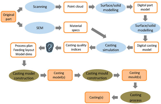
Figure 1.
Processes and their outputs in one-off copy-casting.
2. Scanning
2.1. The Part
The original part to be copied is a cylinder liner from a two-stroke model engine of a car. It has 8 ports, 6 of which are pairwise symmetrical, see Figure 2. Ports play a vital role in engine timing and performance in terms of the power-rotation speed diagram. It is common practice in the model car world to further machine the ports by adding grove-like extensions using a hand tool, typically a dremelTM (Robert Bosch Tool Corporation located in Mount Prospect, IL, USA), so that the fuel is directed to the combustion point and the exhaust gas downwards. These extensions serve a dual role, namely increasing the area of the port and enhancing the swirling flow of the fuel mix into the combustion chamber yielding a more even distribution of the fuel in the chamber. Swirling aids exhaust gas outflow in a way that prevents a significant loss of fuel mix through the exhaust ports. The particular example to be copied proved to have performance much superior to its factory-made counterpart, thus it was desirable to replicate it.
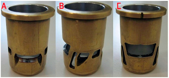
Figure 2.
Model engine liner part: inlet port (A); auxiliary ports (Β) and main outlet port (C).
The part measures 30,400 mm in height and has an external diameter of 9750 mm and a mean wall thickness of 0.750 mm. Thus, the dimensions of groove extensions of its ports are of the order of a few mm. The radial allowance between piston and liner is typically 20–35 μm, whereas the allowance between cylinder and liner is negative. These figures indicate that the outer diameter may need a light finish-turning pass after casting, whereas the inner diameter achieved by casting may be acceptable. As far as port shape accuracy is concerned deviations of the order of 100 μm are considered acceptable as revealed by discussions with model car engineers.
2.2. The Process
Scanning of the liner was performed on a HawkTM (NEXTEC Technologies 2001 Ltd., Tirat Hacarmel, Israel) laser scanner with a NextecTM (NEXTEC Technologies 2001 Ltd., Tirat Hacarmel, Israel) laser head. If the part needs to be scanned in different orientations, it is mounted on a reference frame that can be moved in space using an articulated arm. The frame possesses three spheres of known diameter that define the local X-Y coordinate system. In this way position and orientation of the part with respect to the machine global coordinate system is known at any setup, see Figure 3.
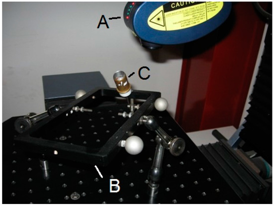
Figure 3.
Laser scanning: head (A); reference frame (B) and part mounted on cantilever arm (C).
There are 5 primitives used in defining scanning paths depending on the geometry of the part, especially curvature variation as well as on its size. These are: Rectangle, Arc, Polyline, Wideline and Polygon. The sensor will automatically move away from the part if the original distance is too small or will move closer to the part, if the original distance were too large. The latter movement may reduce the number of points in the scanning cloud and increase noise as well as collision risk.
Required resolution is determined in two directions, on a scale 0.01 and 0.3 mm (longitudinal or scan direction) and 0.03 to 1 mm (lateral direction), and determines number of points in the cloud and scanning time. Indicatively, an area of 10 mm × 10 mm is scanned in about 50 min at the best resolution 0.03 × 0.03 mm. It is set differently depending on the features to be scanned. A simple feature, for instance, i.e., one whose shape does not change much across its extent, does not need high resolution, whereas a feature with intricate geometry may need not only high resolution but also more than one scanning orientations.
A few test scans were performed initially to conclude that the frame covered excessively large space around the part occluding some of its port features. Therefore, a special arm was constructed and added to the reference frame to hold the part as a cantilever at an angle to the frame plane. This enabled full access of the laser beam to the part being scanned, at different complementary orientations, of course. The only pitfall was a higher risk of collision between the out-of-frame part with the laser head.
Difficulties were encountered due to intricate geometry of the part and high reflectivity of the metallic surface, resulting in much higher scanning time compared to the number of cloud points for the regions concerned. Note that for features of known shape only a section large enough to deduce the characteristic dimensions was scanned. A typical example is the cylindrical outer and inner surface of the liner. The complete point cloud obtained is shown in Figure 4, obviously not covering the full part.
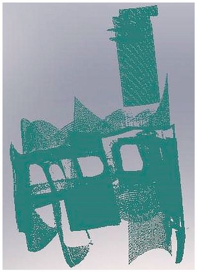
Figure 4.
Point cloud.
3. Digital Part Model
The point cloud resulting from the scanning process as coordinate triplets can be imported by various CAD programs. In this work, SolidWorksTM (Dassault Systèmes S.A., Vélizy, France) was employed including its Scan to 3D plugin. The aim is to convert the point cloud to a surface and ultimately to a solid model of acceptable quality, in order to study possible feeding alternatives in digital simulation as well as to manufacture casting models. No noise reduction was applied, since the number of cloud points were already few in some regions, due to reflectivity etc. problems, see Section 2, and they would have disappeared altogether. Thus, points that were considered to constitute “noise” were removed manually using group selection tools such as lassoing.
An initial mesh is automatically fitted to the point cloud; see Figure 5a. Voids in the point mesh were subsequently repaired manually using the respective software tools. Automatic recognition and fitting of surface splines might be a good choice, if a complete mesh of the whole part is available, since it does not usually allow any editing, surface extensions, repairs etc., but this was obviously impossible in the present case; therefore the manual process was employed. First, the parts of the mesh that seemingly belong to the same surface are automatically identified and painted with a different color for visualization. Sensitivity of recognition is manually adjustable, resulting in larger or smaller groups of surfaces. Selecting the right level of sensitivity is relatively easy when the part is known and understood correctly, as in this case, see Figure 5b. Each registered surfaces has to be assigned a surface type based on the selections available, e.g., plane, cylinder, cone, B-spline etc. During the whole process, handling of the whole of the point cloud at the same time proved computationally heavy, hindering task execution flow. In addition, some flexibility would be necessary regarding intermediate progress or piecewise storage of surfaces fitted and accepted.

Figure 5.
(a) Mesh construction (b) Registration of surfaces through painting (c) Spline surface fitting.
Ports, in particular, posed several problems. Each side of the port could only be identified as a separate spline surface with a need for extension, trimming and knitting, see Figure 6a. The process is tedious and error-prone, e.g., surface patches could not always be extended as much as the user desired, or extension resulted in wrinkling or intersection with neighboring surfaces was not achieved at expected regions obliging to patching up the voids. The net result after tedious manual repairs was not acceptable; see Figure 6b.

Figure 6.
Port surface fitting (a) extension and trimming of separate surfaces; (b) discontinuities.
Thus, a different approach was adopted involving selection of the points defining the outer port profile and from there defining profile splines. This is tedious again, due to the cognitive lack of depth of the selected points but the result is fully controllable. The outer and the inner profile of the port were defined in this way and, where required, intermediate profiles were added. In order to avoid unrealistic wrinkles that emerged when extending the surface radially inward the cylinder, see Figure 7a, guiding (rail) lines were defined; see Figure 7b. Surface lofting operation produced the final surface; see Figure 7c. Symmetrical ports were created about a plane of symmetry.
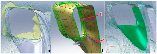
Figure 7.
Port modeling (a) Extension of port entering the void volume; (b) Profile (1) controlling surface shape and guiding lines (2); (c) Part of point cloud with spline profiles, spline guides and lofted spline surface.
The main wall of the part was modeled by first constructing the outer surface mesh corresponding to a cylinder of radius 9.75 mm and the inner surface mesh corresponding to a cone of radius 8.096 mm–8.223 mm and height 25.31 mm. The regions between the cone and the cylinder were filled and all surfaces were knitted to construct a solid. The surfaces of revolution at both ends of the part (cone and rectangular shaped flange) were constructed by first fitting a spline curve to cloud points as a generatrix, see Figure 8. The final part model is shown in Figure 9 and was stored as a binary stl file with Deviation tolerance 0.013 mm and Angle tolerance 5 deg.
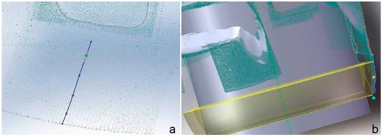
Figure 8.
Modeling the lower conical area of the part (a) Generatrix spline construction; (b) Surface generation.
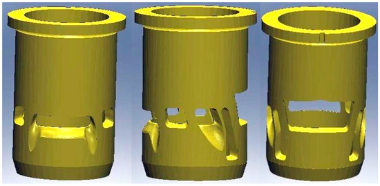
Figure 9.
Part model.
4. Material Investigation
The material of the sample part had to be investigated in order to acquire specifications for casting. The part was examined in a Scanning Electron Microscope (JEOL 6390, JEOL Ltd, Tokyo, Japan) with Energy Dispersive X-ray Analysis (EDX) and a number of measurements were taken at different points in the bulk and in the thin layer of coating in the inner cylindrical surface to ensure credibility, see Figure 10a,b respectively. The results are shown in Table 1.
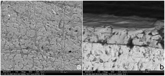
Figure 10.
SEM micrographs (a) main material; (b) internal coating (upper layer).

Table 1.
Scanning Electron Microscopy results.
It was established that the liner consists mainly of copper and zinc, i.e., a brass alloy. A low percentage of carbon found is considered to be due to combustion residuals.
The coating consists of chromium and is usually applied for reasons of resistance primarily to wear and secondarily to corrosion. According to the scale depicted in Figure 10b coating thickness is 44 μm.
5. Casting Simulation
Casting simulation is performed on specialized software with an aim to trying out different vacuum casting parameters and feeding alternatives before physically implementing the process. In this case, ProcastTM (ESI Group, Paris, France) was employed [30], a long-established platform that can solve the thermal, fluid flow (mold cavity filling) and mechanical stress problem at the same time.
5.1. Simulation Setup
It was straightforward to scale up the digital model derived in Section 3 to account for shrinkage allowance. In the case of brass shrinkage is 1.5% [31].
Automatic generation of the finite element tetrahedral mesh was restricted by the user-defined aspect ratio between the largest and the smallest dimension of the three-dimensional elements, conventionally called “delta value”. The delta values determines the size of elements and, as a result, their number, too. Delta values in the range 0.8–0.9 yielded an acceptable match between continuous and discrete domain geometry in the liner case, whereas for values exceeding 1.0 ports start missing important shape details.
The mold can be “virtual” or normal. In the first case mold the software performs design and meshing automatically, whereas in the second case the user designs the mold, specifies element size and creates a surface mesh first and a volume mesh subsequently. Mesh density should be lower at regions of the mold where temperature is not expected to vary intensely, since this is crucial in lowering simulation time. Indicatively, 1.5 million elements correspond to a model size of 700 MB and simulation time of 11 h, whereas 0.5 million elements slash file size to 250 MB and execution time to 2 h. The mesh is checked with the available tools for unacceptable triangles. The latter occur when mismatches between mesh size at neighboring domains occur, e.g., the mold and the casting domains.
In the case of unacceptable triangles, manual correction is necessary, essentially isolating problematic mesh areas and commanding an automatic regeneration of nodes so as to equalize internode distances as much as possible, see Figure 11a. An annoying problem is that fixing triangles in one region may render triangles in another region unacceptable. Thus, surface mesh correction is a tedious process, if too many unacceptable triangles occur. In that case, a new delta value has to be set and the meshing process repeated in the hope of improved quality triangles. The mesh achieved is shown in Figure 11b.
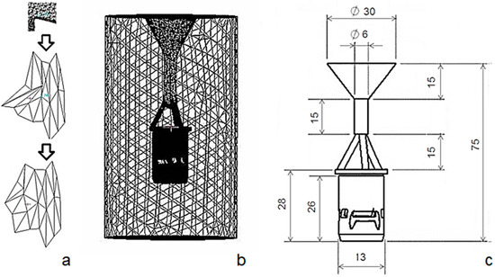
Figure 11.
(a) Mesh correction: unacceptable triangles clipping to desired nodes and smoothing; (b) the two volumetric meshes for mold and casting, respectively; (c) Dimensioned casting with feeding system (units in mm).
Mesh sensitivity analysis in this case was not performed in the traditional way, which is “to get the coarser mesh that produces the mesh-insensitive results”. In our case, a coarse mesh would not converge at all, while a very dense mesh would exceed the system memory limits and the simulation would not run with the resources available. Thus, a relatively dense mesh was used from the start, such that it would allow the analysis to run without failure and in realistic times. The final mesh was very dense in the region of the casting part, and was getting coarser towards the external surface of the mold. Criterion for the mesh sensitivity was solidification time, cooling rate and porosity at two nodes, i.e., one near the port and a second one on the cylinder surface. Acceptability of the mesh is tied to invariability of performance according to the three criteria mentioned above.
After meshing is completed materials need to be assigned, in this case plaster for the mold and brass CuZn33 for the casting. Their properties are retrieved from the database available in ProcastTM. As described in Section 4, two different alloys are present: a copper alloy for the main material, and a chromium alloy for the coating. To model the casting of the copper alloy, temperature dependent material properties are required. This information is not available in the literature. ProCAST features a database of certain materials, including pure copper (Cu), pure zinc (Zn) etc. Based on the chemical composition of Table 1, rule of mixtures is applied to result in the “calculated material properties” of this particular copper alloy. The calculated material properties presented in Figure 12 include temperature-dependent density, thermal conductivity, specific heat, viscosity, as well as the characteristic temperatures (Liquidus–Solidus). The Liquidus temperature used was 931 °C and Solidus was 886 °C (see Figure 12, solid fraction curve), and the latent heat was 205 KJ/kg. In brief, the SEM/EDX information is fed into the model.
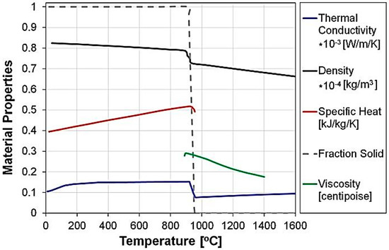
Figure 12.
Temperature-dependent material properties used for the casting simulation.
Next, their interface characteristics need to be assigned, in this case according to experimental investigation of the heat transfer coefficient (HTC) between plaster and brass, see Figure 13. The value of HTC peaks at a high value for the first 2.5 s (stage I), representing the intense heat flow when the molten metal is in very good contact with the mold. Very quickly the HTC reduces to smaller numbers of about 45 W/mm2K (stage II), that correspond to a reduced heat flow due to the air gap formation during solidification. Finally, HTC slightly increasing (stage III) since good solid-to-solid contact is occurring under the prevailing vacuum conditions and for this particular geometry. This time-dependent, 3-stage form is common in the literature [31] and is a function of the materials involved, the casting conditions, the geometry, etc. Since it is a key parameter, and dependent on various factors, it should be estimated for each casting case separately. The value used in this study was calculated based on the methodology described in [23].
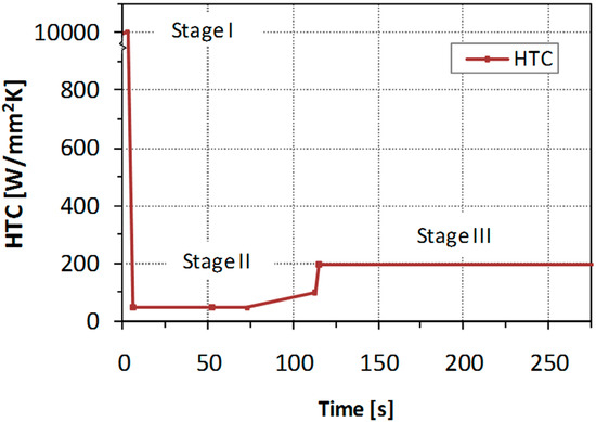
Figure 13.
Plaster-Brass Heat Transfer Coefficient as a function of time, according to [20,23].
Boundary conditions include setting temperature at specific nodes or node groups, i.e., on the mold external surface, as well as melt pouring velocity or mass flow rate (approximated using Bernoulli equation at 1.10672 Kg/s) and pressure at the mold-casting interface (0.03 bar for vacuum casting) and on the outer surface of the mold (1 bar). Initial conditions concern mainly initial temperature of the mold and the melt.
Furthermore, computational process parameters referring to numerical solution procedure were set according to the software guide rules [30].
5.2. Results
Three sets of digital experiments were performed, namely (i) a set with fixed mold temperature in which three different feeding system designs and two different mold temperatures were tried (ii) a set with a fixed feeding system and a melt temperature selected from the previous set, in which three mold temperatures were tried (iii) a fixed case selected from the second set of experiments in order to simulate in detail shrinkage and dimensional accuracy of the casting. The full set of conditions examined is presented in Table 2.

Table 2.
The full set of digital experiments performed.
5.2.1. Different Feeding System and Melt Temperatures
For a fixed mold temperature at 730 °C two melt temperatures, i.e., 970 °C and 1000 °C, were tried each on a different feeding system consisting of 3, 4 and 5 runners. The results concerning porosity are shown in Figure 14. Porosity is reduced as the number of runners increases. At the melt temperature of 1000 °C porosity is generally lower but the number of local defects (voids and porosity) near ports increases. The five-runner case is obviously better than the other two.

Figure 14.
Porosity for melt temperatures (a) 970 °C and (b) 1000 °C and three feeding alternatives.
Based on previous experience, casting conditions outside the temperature range presented in this paper, were usually resulting in incomplete filling (e.g., Tmelt ~950 °C) of the cavity or significant levels of surface oxidation (e.g., Tmelt > 1000 °C). Therefore, the temperatures of 970 °C and 1000 °C were selected as possibly viable conditions to try. Note that it is the temperature difference between the melt and the mold that matters. To sum up, for the purposes of this study, the requirements of the trials were: to identify casting parameters that would produce a faithful reproduction of casting shape, not extreme oxidation/burn-outs, acceptable levels of porosity and reasonably low solidification time.
5.2.2. Different Mold Temperatures
Taking the five-runner case at a melt temperature of 1000 °C three mold temperatures were tried at 660 °C, 730 °C and 800 °C. Figure 15 depicts the results in terms of solidification time and porosity.

Figure 15.
Best feeding alternative for three mold temperatures (a) Solidification time; (b) Porosity.
The criteria for the selection of the best mold temperature are:
- The porosity levels to be within an “acceptable” limit, which in this case, was set to 0.01 in line with the simulation software user guide, in order to avoid macroporosity [30]),
- Uniformity of porosity levels within the cast part (excluding the feeding system),
- Uniformity of solidification time throughout the cast part volume,
- Avoidance of gaps (voids), especially in the regions around the “ports”.
It is clearly shown that at 730 °C mold temperature best results are achieved. At 800 °C the melt cools down slowly, solidification starting from the runner outlet. The inner part remains at high temperatures, i.e., in the intermediate liquid-solid phase for a relatively long time, resulting in intense macroporosity. At 660 °C the problem is not so pronounced, but it still exists. In general, porosity is increased at the top of the part just after the runner outlet.
Concerning the porosity levels, it is true that the values are rather low. Porosity values might range from 0 to 1, anything larger than 0.01 being considered as macroporosity. The appearing micro-porosity is actually an indication of acceptable quality in both casting cases. Despite the low values, the effect of the casting parameters on the formation of porosity is prominent. The tendency of preferable formation of porosity in certain locations is shown. Uniformity in the casting was the criterion used to select the one casting scenario over the other.
5.2.3. Stress and Distortion for the Best Casting Case
For a 5-runner system, melt temperature 970 °C and mold temperature 730 °C which appeared to be a good combination, shrinkage distortion of the part was simulated during the whole process down to room temperature. In particular, two different boundary conditions were applied, i.e., standard vacuum conditions for the first 511 s and then full atmospheric condition with cooling in water at 15 °C. The latter corresponded to removal of the flask from the vacuum casting machine and immersion in water, constituting standard practice in investment casting processes. Total displacement of the part is shown in Figure 16a, while the gap formed between mold and casting owing to shrinkage is shown in Figure 16b.
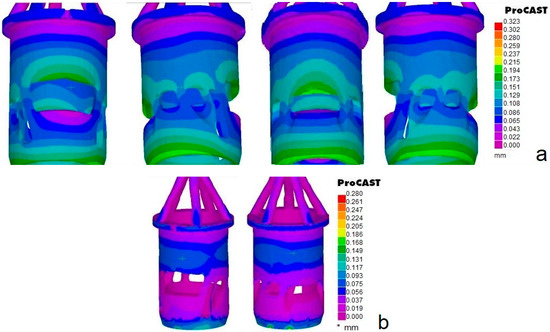
Figure 16.
Casting distortion for the best casting case (a) Total displacement; (b) Gap prediction.
Maximum displacement of 0.323 mm is manifested in the feeding system, but in the part itself maximum shrinkage is 0.022 mm. However, displacement is not homogenous, see Figure 16a. At regions where most material is concentrated, e.g., when ports are small, displacement is largest, whereas underneath larger ports it is reduced. In addition, taking into account the gap formed, see Figure 16b it is easy to note the differences between the mold and the casting. The largest gap is observed at the lowest part conical ending, whereas in the inner part of the cylinder and underneath the ports gap is minimal.
6. Casting Implementation
A standard investment casting procedure of the lost-wax type was implemented [31] as briefly described next. Note that the best of the alternatives tried using casting simulation was implemented, i.e., a 5-runner system, 970 °C melt temperature and 730 °C mold temperature, see Section 5.
6.1. Procedure
If just one casting needs to be made, then a 3D printer can be used to make the casting model directly without use of dies. Due to the fine resolution required fabrication time is high and special 3D printers are employed, in this case Solidscape R66TM (Solidscape, Inc., Merrimack, NH, USA) dedicated to casting of jewelry and dental restorations. Wax-like resins are used as pattern material with zero shrinkage and enhanced strength. The wax model produced is shown in Figure 17. Note that some remains of support structure are visible as darker blobs.
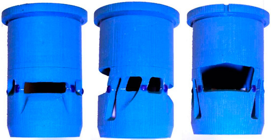
Figure 17.
Wax model resulting from 3DP.
The feeding system consisting of the sprue basin, the sprue and the feeding runners is made up of standard wax parts assembled together by hand using a soldering iron, which is a delicate process. The same technique is used to assemble the feeding system to the wax model, thus making up the wax tree.
As soon as the wax tree (in this case with just one part) is prepared, it is put on the rubber base, see Figure 18a and surrounded by the metal flask. Plaster (R&R Argentum InvestmentTM, Ransom and Randolph, Maumee, OH, USA) is gradually mixed with de-ionized water (mixing proportion 100:39 by weight) and de-aired for about 1.5 min, see Figure 18b, then it is filled into the flask trying to avoid direct feeding onto the wax tree and this is de-aired again for 2 min, Figure 18c. De-airing takes place on a special machine whose table can vibrate at the same time, see Figure 18d. After about 1hr the plastered flask has acceptable hardness to be removed together with the rubber base and be placed into the dewaxing oven for 3.5 h, see Figure 18e. This is followed by heating the plaster mold in a separate oven, see Figure 18f, at 350 °C for 2 h and then at 730 °C for another 3.5 h, see Section 5.2. The plaster material used has a shrinkage of less than 1.6% in the temperature range 20–900 °C. However, above 600 °C shrinkage is practically zero, thus dimensional accuracy of the casting is not expected to be affected.
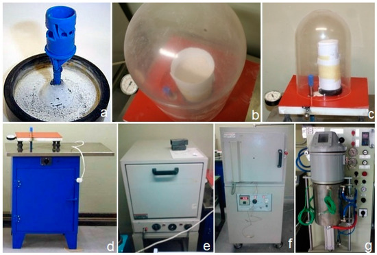
Figure 18.
(a) Wax pattern with runners on rubber base before placement in the flask; (b) plaster de-airing; (c) flask de-airing; (d) degasser; (e) dewaxing oven; (f) plaster baking oven; (g) vacuum casting machine.
Casting is performed by placing the mold into the vacuum casting machine, see Figure 18g, melting the appropriate quantity of brass in the inbuilt crucible and allowing it to fill the mold cavity with vacuum assistance. After 8.5 min the mold is removed from the machine and immersed in water, which causes its shattering to reveal the casting, see Figure 19a.

Figure 19.
Casting (a) uncleaned tree (b) cleaned part.
6.2. Casting Quality
The casting after cutting of the feeding system and cleaning is shown in Figure 18b. Part accuracy was measured using the same equipment and procedures employed to scan the original. In particular, three types of measurements were made on the HawkTM laser scanner and were used to fit surfaces and obtain the main dimensions of the part. The measurement areas were: a narrow stripe covering the full height of the part, two areas on the external cylindrical surface and a restricted area of the inner surface of the part, to the extent allowed by the available opening. The main dimensions of the original, the wax model and the cast copy obtained are shown in Table 3. The relative error of the copy with respect to the original is generally low, especially concerning the height dimension. Mean surface finish of the part was measured using a Taylor Hobson Surtronic 3TM (AMETEK Inc., Berwyn, PA, USA) instrument as Ra = 3.2 μm, higher than the original’s 1.2 μm, which indicates the need for some finishing.

Table 3.
Main dimensions of the parts constructed.
7. Discussion
This work aimed at investigating the details and decisions involved in the individual links of the process chain concerning production of one (or very few) castings based on a prototype to be replicated. It is assumed that the techniques involved are mature enough to warrant acceptable results in terms of quality, as explained in the “Introduction”, provided that these techniques are applied appropriately, the issue being how the latter is ensured.
A general note on methodology is that in many reverse engineering studies reported in literature a 3D printed part is scanned and compared with the part model, typically employing color plots of deviations. The casting is also scanned and similarly compared with the original part when applying copy-casting. This is followed, if the emphasis is put on engineering analysis in order to prove that the 3D printing technique and the casting method are accurate enough. However, this was not the aim of this study, since the scanning technique, the 3D printing technique (including material shrinkage) and the casting technique (including material shrinkage. too) are all mature enough to be have an associated guaranteed maximum error as provided by the pertinent manufacturers. In addition, in a production environment the laser scanning and reconstruction technique employed is too time-consuming to be applied twice after scanning the original part, i.e., once for the 3D printed part and once for the casting. Thus, it is neither practical nor necessary to plot pairwise deviations of complete models. Instead, a good indication of the overall accuracy achieved was obtained by measuring the main dimensions of the part, of the wax model and of the casting by conventional means or by scanning selected areas of the objects.
7.1. Part Digitising
Besides laser scanning, CMM and optical scanning are used to record point clouds from which a 3D mesh and ultimately a solid model are created. Industrial computer tomography can also be used, but its accuracy is relatively low [13]. Laser scanning and CMM possess high accuracy, of the order of a few μm down to 1 μm and can yield structured point clouds along programmed scanning paths. However, CMM is too slow for scanning, though good for digitizing, whereas laser scanning is faster by an order of magnitude. Optical scanning using CCD cameras, often with structured light, records potentially thousands of points and very quickly, too, i.e., orders of magnitude quicker than its laser counterpart. However, accuracy is worse, typically around 8–10 μm and there may be problems in ensuring complete coverage of the object, e.g., in the case of deep recesses and blind spots due to occlusion [28]. In the case of small intricate parts, such as in the case study, laser scanning seems to offer the best compromise between accuracy, time and coverage. In addition, in order to reduce scanning time the type of surface being scanned should be exploited, e.g., just the generatrix of a cylinder may be scanned instead of its full surface.
7.2. Part Modelling
Fitting sculptured surfaces to cloud points may be extremely time-consuming, if the wrong strategy is adopted. The fitting strategy depends on experience, since it is connected to available coverage of the region by cloud points and to the shape details as such. In particular, if a large number of points were available to define a surface, then the only perceivable obstacle would be the uniformity of digitizing accuracy in order to avoid local deformations. On the contrary, if parts of the point cloud are absent, patching or generally repair work is needed using appropriate software, which normally requires also knowledge of nature of the missing area, its continuity constraints etc. As far as surfaces of known type are concerned the fitting process proved to be straightforward, as expected.
7.3. Material Identification
Material identification has been pinpointed as an issue often overlooked in reverse engineering projects [18]. Determining the part’s material follows a standard procedure; however, if multiple materials are combined, this typically being the case with coatings, measurements on part sections need to be made and appropriate techniques for measuring thickness of different layers must be adopted. The difficulty in this case lies in the destructive nature of most of these techniques.
7.4. Virtual Casting
Casting simulation is a novel link that was introduced in the digital manufacturing chain in this work. It was found to be very useful in that it enables elimination of feeding system designs that are obviously useless as well as focus on promising values of casting parameters. Among all papers, mainly case studies, that were found in literature dealing with rapid casting of parts based on an original to be replicated [1,2,5,6,7,11,13,16,17,19,25,26,29], all but three tacitly admit that a right-first-time casting can be achieved, obviously by selecting casting feeding and process parameters according to experience. The three exceptions [16,19,29] used simulation to check that the single envisaged casting system design was suitable, i.e., without trying out alternatives. By contrast, in this work it is advocated that casting simulation needs to be used to streamline feeding system design of the casting.
In addition, note that this paper does not concentrate on validating casting simulation. Thus, one has to accept simulation models as validated elsewhere, e.g., [20,23]. It is worth noting that simulation does not suggest good solutions, but rather assesses solutions suggested by the human. In addition, the HTC to be used which depends on the materials of the mold and the casting as well on their shape is a potential pitfall. HTC needs to be adopted from similar cases found in technical literature, or otherwise it needs to be determined numerically by reference to experiments, see for instance [23], which is time consuming.
7.5. Casting Tool Construction
The casting implementation used is typically employed in jewelry casting, especially for larger items, i.e., for relatively few wax models on the same tree, and it is not considered specific to either materials or shapes. In cases where just one or a few small parts need to be cast, 3D printing of the relevant patterns followed by mold construction as adopted in this work is perfectly acceptable, since the extra time devoted to mold construction is a few hours. This delay could obviously be eliminated if the mold were directly constructed using appropriate AM technology. Many advanced rapid casting systems in use today follow this route but the cost of making a wax model is by no means comparable to the cost of making the corresponding ceramic mold using AM [4].
Besides, making the wax tree by AM for one or a few parts may take time comparable to the time that it would have taken for the corresponding metal parts to be directly manufactured on similar equipment following the Selective Laser Sintering/Melting paradigm. However, in the latter case surface quality would have been worse than that obtained by precision casting [1]. In addition, there are large differences in wax-based prototyping in terms of time, which are attributed to the printers’ fundamental technology employed, e.g., spraying mode, droplet size etc. [4].
On the other hand, if a larger number of castings were needed, 3D printing would probably be too expensive and would need to be replaced by a process where a metal pattern is manufactured and used to make a die from silicon rubber, which, in turn, would be used to make wax models as many times as necessary. Alternatively, direct wax injection into a die may be preferable [4].
8. Conclusions
Precision casting is an interesting alternative to machining for small and intricate parts such as the cylinder liner tackled in this work. The digital manufacturing process chain involves point-digitizing the original with an accurate enough scanner, constructing a digital model on a CAD system, determining the material of which the original part consists, simulating the casting process with different alternatives concerning feeding system and casting parameters, constructing the wax model using AM, manually constructing the mold, and finally performing the casting on a precision casting machine. Each individual step of this chain was found to involve a number of intricacies.
The following “recipe” is advisable when just one part is to be replicated: digitize the part using an accurate enough scanner. When accuracy required is below 10 μm a laser scanner is necessary, in which case smart selective scanning of specific areas as opposed to a point cloud covering the whole part slashes scanning duration. As a result, similarly smart surface fitting and object reconstruction is necessary on a geometric modeling system afterwards. Material investigation using SEM or analogous techniques, depending on whether part destruction (locally or not at all) is allowed, is also necessary to complete part design specifications. Casting simulation on specific software using validated input data, esp. heat transfer coefficient for the materials and shapes employed, is strongly advised in order to save a lot of experimentation with molds and casting parameters. The main parameters to be investigated by simulation refer to the feeding system design, starting with the number of runners and their dimensions, and the casting parameters, starting with melt and mold temperature. The main criteria on which casting quality is judged should be shape fidelity, porosity, solidification time and shrinkage distribution. The best alternative identified by simulation should be implemented. Wax or wax-like models are worth making on a 3D printer of casting caliber. Casting implementation does involve the human, mainly in making the mold using plaster or similar materials and apparatus, whereas automated vacuum casting machines remove most ambiguities associated with manual handling.
All in all in this chain, mold making in the casting process is the crucial link in terms of assuring part quality. Still, interlinked digital tools were shown to contribute a great deal towards ensuring acceptable quality and time in making one-off copies of precision parts.
Author Contributions
G.-C. Vosniakos supervised the research and wrote up the paper, S. Mihail performed all experimental work and A. Vasileiou directed casting simulations.
Conflicts of Interest
The authors declare no conflicts of interest.
References
- Karunakaran, K.P.; Bernard, A.; Suryakumar, S.; Dembinski, L.; Taillandier, G. Rapid manufacturing of metallic objects. Rapid Prototyp. J. 2012, 18, 264–280. [Google Scholar] [CrossRef]
- Ramos, A.M.; Simões, J.A. CAD-CAM-RTV–lost-wax casting technology for medical implants. Rapid Prototyp. J. 2009, 15, 211–215. [Google Scholar] [CrossRef]
- Cheah, C.M.; Chua, C.K.; Lee, C.W.; Feng, C.; Totong, K. Rapid prototyping and tooling techniques: A review of applications for rapid investment casting. Int. J. Adv. Manuf. Technol. 2004, 25, 308–320. [Google Scholar] [CrossRef]
- Chhabra, M.; Singh, R. Rapid casting solutions: A review. Rapid Prototyp. J. 2011, 17, 328–350. [Google Scholar] [CrossRef]
- Bassoli, E.; Gatto, A.; Iuliano, L.; Violante, M.G. 3D printing technique applied to rapid casting. Rapid Prototyp. J. 2007, 13, 148–155. [Google Scholar] [CrossRef]
- Pal, D.; Ravi, B. Rapid tooling route selection and evaluation for sand and investment casting. Virtual Phys. Prototyp. 2007, 2, 197–207. [Google Scholar] [CrossRef]
- Chua, C.K.; Feng, C.; Lee, C.W.; Ang, G.Q. Rapid investment casting: Direct and indirect approaches via model maker II. Int. J. Adv. Manuf. Technol. 2004, 25, 26–32. [Google Scholar] [CrossRef]
- Pattnaik, S.; Karunakar, D.B.; Jha, P.K. Developments in investment casting process—A review. J. Mater. Process. Technol. 2012, 212, 2332–2348. [Google Scholar] [CrossRef]
- Yarlagadda, P.K.D.V.; Hock, T.S. Statistical analysis on accuracy of wax patterns used in investment casting process. J. Mater. Process. Technol. 2003, 138, 75–81. [Google Scholar] [CrossRef]
- Sabau, A.S.; Viswanathan, S. Material properties for predicting wax pattern dimensions in investment casting. Mater. Sci. Eng. A 2003, 362, 125–134. [Google Scholar] [CrossRef]
- Ferreira, J.C.; Alves, N.F. Integration of reverse engineering and rapid tooling in foundry technology. J. Mater. Process. Technol. 2003, 142, 374–382. [Google Scholar] [CrossRef]
- Liu, G.H.; Wong, Y.S.; Zhang, Y.F.; Loh, H.T. Modelling cloud data for prototype manufacturing. J. Mater. Process. Technol. 2003, 138, 53–57. [Google Scholar] [CrossRef]
- Cheng, Y.; Wang, L.; Zhu, Z.; Zhang, D. Geometric analysis of investment casting turbine blades based on digital measurement data. China Foundry 2014, 11, 20–27. [Google Scholar]
- Li, L.; Schemenauer, N.; Peng, X.; Zeng, Y.; Gu, P. A reverse engineering system for rapid manufacturing of complex objects. Robot. Comput. Integr. Manuf. 2002, 18, 53–67. [Google Scholar] [CrossRef]
- Salvi, J.; Matabosch, C.; Fofi, D.; Forest, J. A review of recent range image registration methods with accuracy evaluation. Image Vis. Comput. 2007, 25, 578–596. [Google Scholar] [CrossRef]
- Ferreira, J.C.; Mateus, A.S.; Alves, N.F. Rapid tooling aided by reverse engineering to manufacture EDM electrodes. Int. J. Adv. Manuf. Technol. 2006, 34, 1133–1143. [Google Scholar] [CrossRef]
- Zhang, D.H.; Jiang, R.S.; Li, J.L.; Wang, W.H.; Bu, K. Cavity optimization for investment casting die of turbine blade based on reverse engineering. Int. J. Adv. Manuf. Technol. 2009, 48, 839–846. [Google Scholar] [CrossRef]
- McEvily, A.J. Reverse engineering gone wrong: A case study. Eng. Fail. Anal. 2005, 12, 834–838. [Google Scholar] [CrossRef]
- Bernard, A.; Delplace, J.; Perry, N.; Gabriel, S. Integration of CAD and rapid manufacturing for sand casting optimisation. Rapid Prototyp. J. 2003, 9, 327–333. [Google Scholar] [CrossRef]
- Vassiliou, A.N.; Pantelis, D.I.; Vosniakos, G. Investigation of centrifugal casting conditions influence on part quality. In Proceedings of the International Conference on Manufacturing Engineering, Halkidiki, Greece, 1–3 October 2008; pp. 347–356. [Google Scholar]
- Gramegna, N.; della Corte, E.; Poles, S. Manufacturing process simulation for product design chain optimization. Mater. Manuf. Process. 2011, 26, 527–533. [Google Scholar] [CrossRef]
- Iqbal, H.; Sheikh, A.K.; Al-Yousef, A.; Younas, M. Mold design optimization for sand casting of complex geometries using advance simulation tools. Mater. Manuf. Process. 2012, 27, 775–785. [Google Scholar] [CrossRef]
- Vasileiou, A.; Vosniakos, G.; Pantelis, D. Determination of local heat transfer coefficients in precision castings by genetic optimisation aided by numerical simulation. Proc. Inst. Mech. Eng. Part C J. Mech. Eng. Sci. 2014, 16. [Google Scholar] [CrossRef]
- Singh, J.P.; Singh, R. Investigations for a statistically controlled rapid casting solution of lead alloys using three-dimensional printing. Proc. Inst. Mech. Eng. Part C J. Mech. Eng. Sci. 2009, 223, 2125–2134. [Google Scholar] [CrossRef]
- He, J.; Li, D.; Lu, B.; Wang, Z.; Zhang, T. Custom fabrication of a composite hemi-knee joint based on rapid prototyping. Rapid Prototyp. J. 2006, 12, 198–205. [Google Scholar] [CrossRef]
- Zhang, Y.; Liu, H. Application of rapid prototyping technology in die making of diesel engine. Tsinghua Sci. Technol. 2009, 14, 127–131. [Google Scholar] [CrossRef]
- Wang, L.; Li, H.; Gui, Y.; Zhao, G. A rapid design and manufacturing system for product development applications. Rapid Prototyp. J. 2004, 10, 200–206. [Google Scholar]
- Sokovic, M.; Kopac, J. RE (reverse engineering) as necessary phase by rapid product development. J. Mater. Process. Technol. 2006, 175, 398–403. [Google Scholar] [CrossRef]
- Pal, D.; Ravi, B.; Bhargava, L.; Chandrasekhar, U. Rapid casting development using reverse engineering, rapid prototyping and process simulation. Indian Foundry J. 2005, 51, 23–34. [Google Scholar]
- ESI Group. PROCAST v2004.1; ESI Group: Paris, France, 2004. [Google Scholar]
- Campbell, J. Castings-The New Metallurgy of Cast Metals; Butterworth Heinemann: Oxford, UK, 2003. [Google Scholar]
© 2017 by the authors. Licensee MDPI, Basel, Switzerland. This article is an open access article distributed under the terms and conditions of the Creative Commons Attribution (CC BY) license (http://creativecommons.org/licenses/by/4.0/).