1. Introduction
Dieless single-point incremental sheet metal forming (SPIF) by a tool having a single point of contact is a highly adaptable process whereby the part is formed by the movement of a hemispherical tool along a characterized path. SPIF technology is different from other sheet metal forming methods, such as spinning, piercing, deep drawing, and bending. The mechanism of SPIF is plastic deformation caused by directing a forming tool via a path on the sheet metal using a computer numerical control (CNC) machine [
1].
Since SPIF is a dieless process, it is suitable to form complicated prototype profiles within a short period at low cost. The most popular parts that were made by SPIF have been used in aerospace or medical applications [
2]. Due to the feasibility shown by SPIF, new applications were presented, such as applying heat in forming hard-to-form, high-strength sheet metals.
A new generation in SPIF has started to apply the heat in different ways during forming to form high-strength sheet metals. Laser heating was investigated by [
3] where two moving systems were used: one was a robot to move the tool and the other was a 3D coordinator to guide the laser on the sheet. Furthermore, conduction heating was suggested by [
4] to heat the sheet metal by electric heaters for forming a 5083 aluminum magnesium alloy.
Another heating method was presented that involved exerting hot oil to increase the sheet metal temperature as described in [
5]. In other investigations, an electrical current was applied that passed through the tool to heat up the sheet, which was studied by [
6] to form a titanium alloy TiAl
2Mn
1.5. A hot air medium was tested in [
7] as the temperature of AZ31 alloy was increased to 250 °C and formed it into complicated shapes. Resistance heating was suggested by [
8], using two tools held by robots: one to form and the other to support and heat the sheet metal to 600 °C.
It can be concluded from the literature review that there is no heating method accompanied with SPIF that can increase the sheet metal temperature over 750 °C other than with a laser. However, the laser method was specialized by its complexity.
SPIF has still not been implemented widely in industry for numerous reasons, including:
Lack of geometrical accuracy in high-strength produced parts [
9,
10];
Limited applications, especially for high-strength metals;
Lack of suitability for difficult-to-manufacture parts with a perpendicular wall angle, such as deep drawing;
Suitable only for prototype manufacturing because of the time consumed during tool travel along its designed path; and
Different component properties in comparison to the conventional sheet metal forming technologies.
This paper proposes a method to increase the importance of SPIF by demonstrating induction heating synchronized with SPIF, or induction-assisted SPIF (IASPIF). The availability of a viable induction heating method with SPIF would increase the interest in it. An advantage of our approach is that high-strength sheet metals can be simply formed into complex geometries by adopting a simplified mechanism.
2. Materials and Methods
The sheet metal blanks and their specific parameters for our dieless SPIF investigation were tested by many devices to improve the efficacy of the suggested process. It became clear that the process parameters have a very large influence on the experimental results.
HCT980C dual-phase steel is well known as an advanced high-strength steel (AHSS) and was investigated using a sheet with a thickness of 1.2 mm. The steel alloy was supplied by ThyssenKrupp Stahl-Service-Centre (Radebeul, Germany). The full specifications and properties of the mentioned steel alloy can be found in [
11].
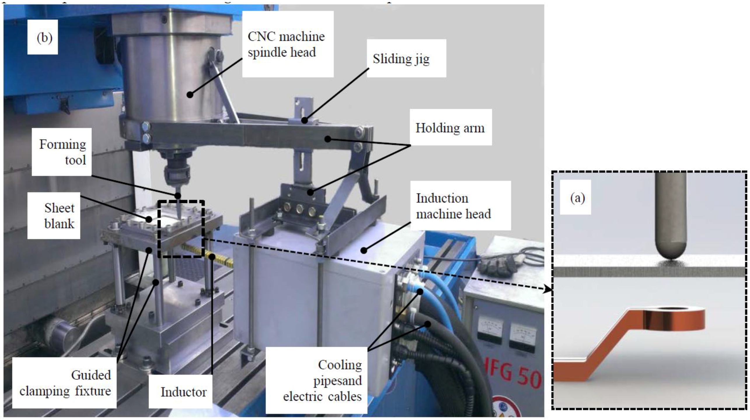
The experimental setup of the dieless single-point incremental forming process assisted by induction heating was the same as that used in [
12] and is illustrated in
Figure 1. The forming tool material was made from hot-worked tool steel X210Cr12 (1.2080) with a diameter of 12 mm. The tool is fully quenched and hardened to 64 HRC and forming tips with diameters of 6 and 12 mm were used. A high frequency induction generator was used with a maximum power capacity of 50 kW and the magnetic radiation frequency was 325 kHz.
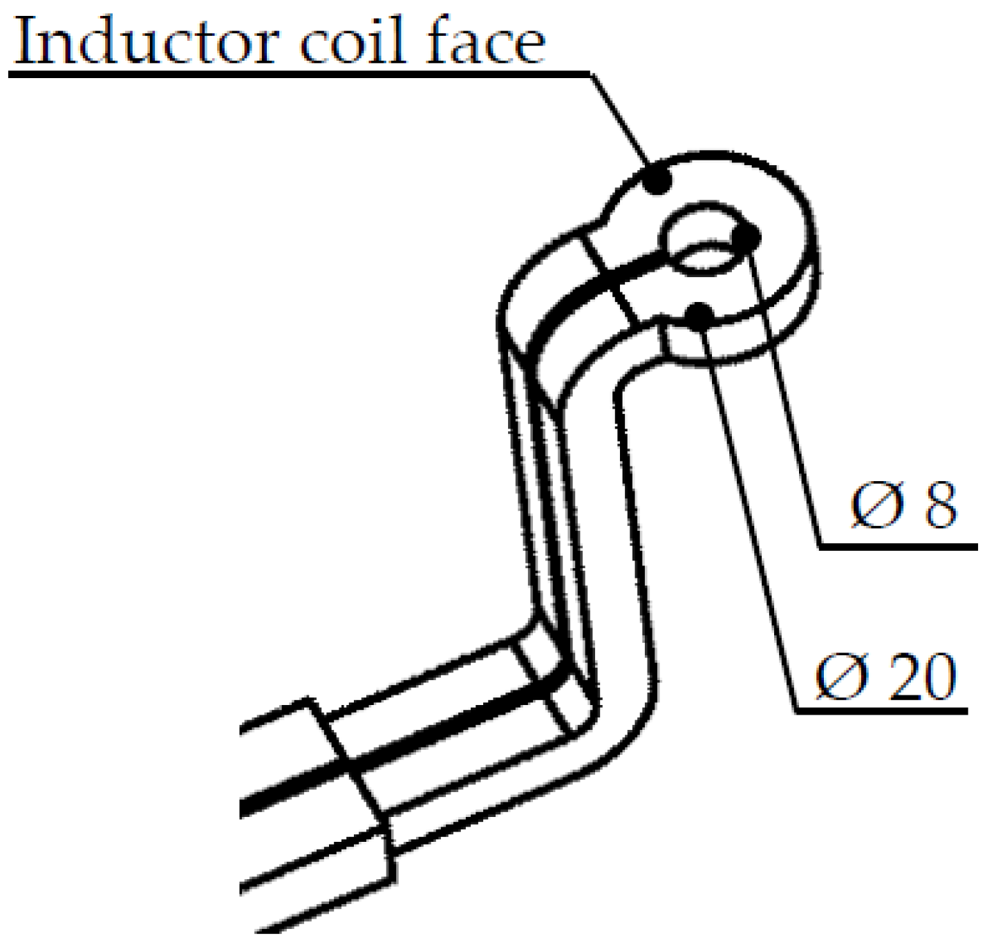
An induction coil was connected to the induction generator head which moved simultaneously with the forming tool. A one-turn induction coil utilized in the experiments had outer and inner diameters of 20 and 8 mm, respectively. The coil was made from a rectangular profile with a width of 6 mm shaping the coil face. It also had a depth of 4 mm, as shown in
Figure 2.
The suggested profile geometry was designed by the SOLIDWORKS software and then exported into a step file to obtain the tool path code that is used by the CNC milling machine. The tool path code program was made by a CAM-software named ESPRIT. A Kistler dynamometer (type 9255Asp) made by Kistler Instrumente AG (CH-8408 Winterthur, Switzerland) was utilized to enhance the resulting forming forces.
There were difficulties measuring the generated heat in the assembled system. The thermocouple could not be used because of the continuous movement of both the forming tool on the upper portion and the induction coil in the lower portion of the sheet. Therefore, the induction heating temperature was measured by an infrared (IR) camera (InfraTec type VarioCAM
®) produced by ESW GmbH (Wedel, Germany), which has a measuring range from −40 to 1700 °C. The measuring frequency was 2 Hz (2 pictures/sec). The IR camera was adopted to measure the lower portion of the sheet temperature, as in [
13].
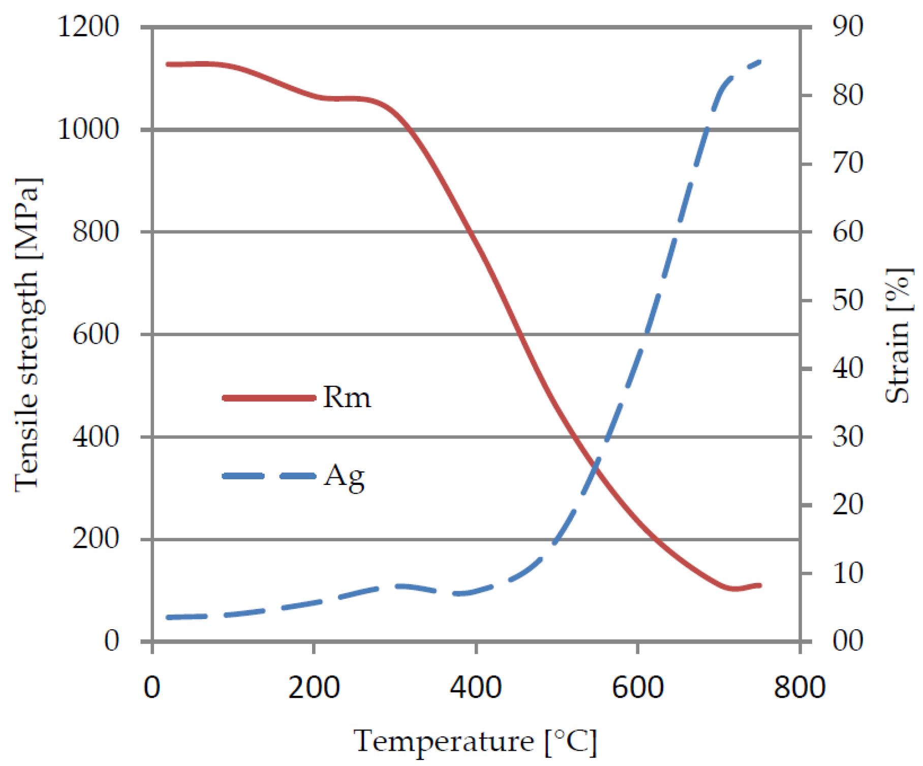
2.1. Effect of Heat on the Formability of the HCT980C Steel
As indicated in
Figure 3, the increase in temperature caused a reduction in tensile strength and an increase in ductility due to the transformation of the martensitic phase into pearlite and ferrite. These results were obtained by heating up the material to the desired temperature, soaking up to 20 min and then performing the tensile test. The heating oven was attached to the tensile test machine and the temperature was applied during the tensile test. The tensile tests were carried out according to standard DIN EN 10002-5 by a universal tensile testing machine manufactured by Hegewald and Peschke, GmbH (Nossen, Germany).
2.2. Experimental Conditions
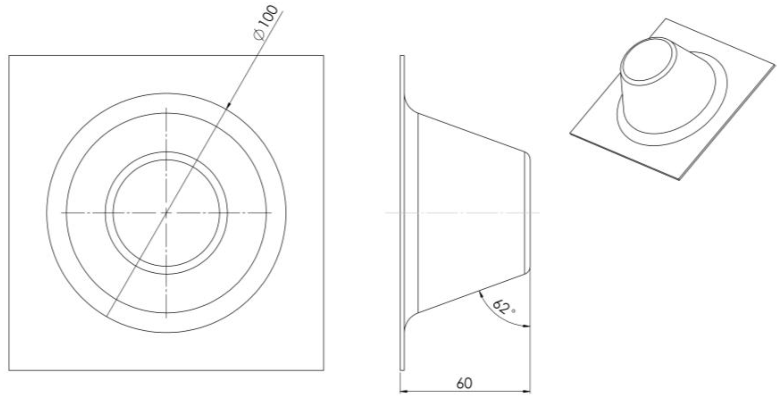
The experimental method consisted of producing a conical shape 100 mm in diameter from the previously stated steel alloy at both room and elevated temperature. The forming parameters used were as follows:
The incremental step depth in the z-direction for the milling machine was chosen to be ΔD = 0.5 mm.
The starting cone wall angle was 60° then it was increased until failure. The cone depths were then 50 and 70 mm.
A graphite powder was sprayed onto the sheet face as a dry lubricating medium because it is not possible to use a liquid lubricant at high temperatures.
The original dimensions of the tested sheet blank were 190 mm × 190 mm.
No supporting plate was applied in the experiments due to the movement of induction coil in the lower side of the sheet.
Tensile test samples were cut by a water jet cutting machine from profiles that were formed from a 150 × 150 mm pyramid. Additionally, these samples were utilized to investigate the resulting strength for the HCT980C steel after induction heating.
2.3. Additional Tests to Improve the Feasability of the Suggested Study on the HCT980C Steel
The formed profiles were scanned by an Atos Core 200 measuring system manufactured by GOM-Gesellschaft für Optische Messtechnik mbH (Braunschweig, Germany). The microhardness tests were conducted on an M1C automated hardness testing system manufactured by EMCO-TEST Prüfmaschinen GmbH (Kuchl, Austria).
3. Results and Discussion
The results contained useful information about HCT980C steel behaviour during dieless hot SPIF. The formability was increased by forming cone wall angles of 62° for HCT980C steel. A new forming technique was developed by forming with variable feed rates during the operation. Initial investigations were done without applying induction heating, forming at room temperature to compare to the parts that were formed by applying induction heating later at elevated temperatures.
3.1. The Effect of Induction Power on the Geometrical Accuracy
The accuracy of the conical parts that were formed from HCT980C steel was measured by a GOMATOS scanning system as the cone profile was clamped by a fixture to guarantee the exact measuring position, as stated in [
14]. The scanned profiles represent the formed parts produced during the experiment. The scanned profiles were merged and compared with those designed by the CAD program SOLIDWORKS. The rapprochement between the scanned and the CAD models was done by applying the GOM inspect program. The actual model was placed over the CAD model for the comparison.
Figure 4 shows the CAD model of the cone shapes used in this study. Each point on the CAD model was compared with the respective points in the actual model and the combined deviations of the two models appeared as color-scaled deviations.
The most striking results came from the comparison of the scanned profiles and CAD models as indicated in
Figure 5. The higher the induction power, the lower the difference between the CAD and scanned profiles. These results correlate satisfactorily with Magnus [
15] (p. 118) which stated that a more accurate geometry was formed by a higher laser power that generated higher temperatures.
The negative deviations presented in
Figure 5 mean that the scanned part level is lower than the CAD profile level. However, the positive deviations express that the scanned part level is higher than the CAD profile level.
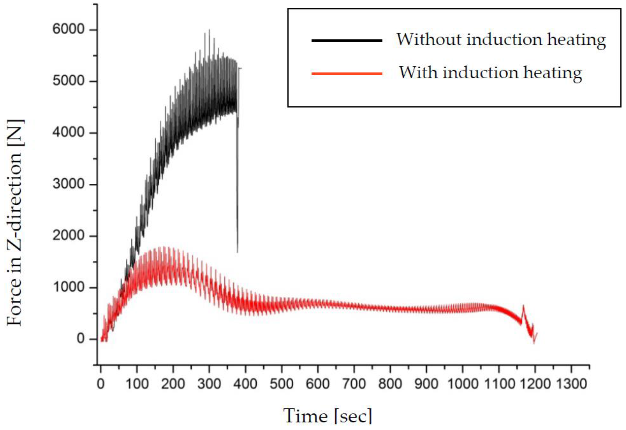
3.2. The Effect of Induction Heating on the Forming Forces
The measured forming forces are shown in
Figure 6 for HCT980C steel.
The forces in the z-direction without induction heating (room temperature) exceed 5500 N. The forces during induction heating were limited to 1850 N. It is, therefore, not possible to form the HCT980C steel at room temperature.
The high fluctuation in the forming forces was also discovered by [
16]. The pulsing phenomenon in the forming forces was caused by continuous movement of the forming tool on the sheet blank. A calibration process was performed to validate the measured forces in the z-axis direction equal to ± 5 N.
3.3. Influence of Induction Heating on the Microhardness and Mechanical Properties
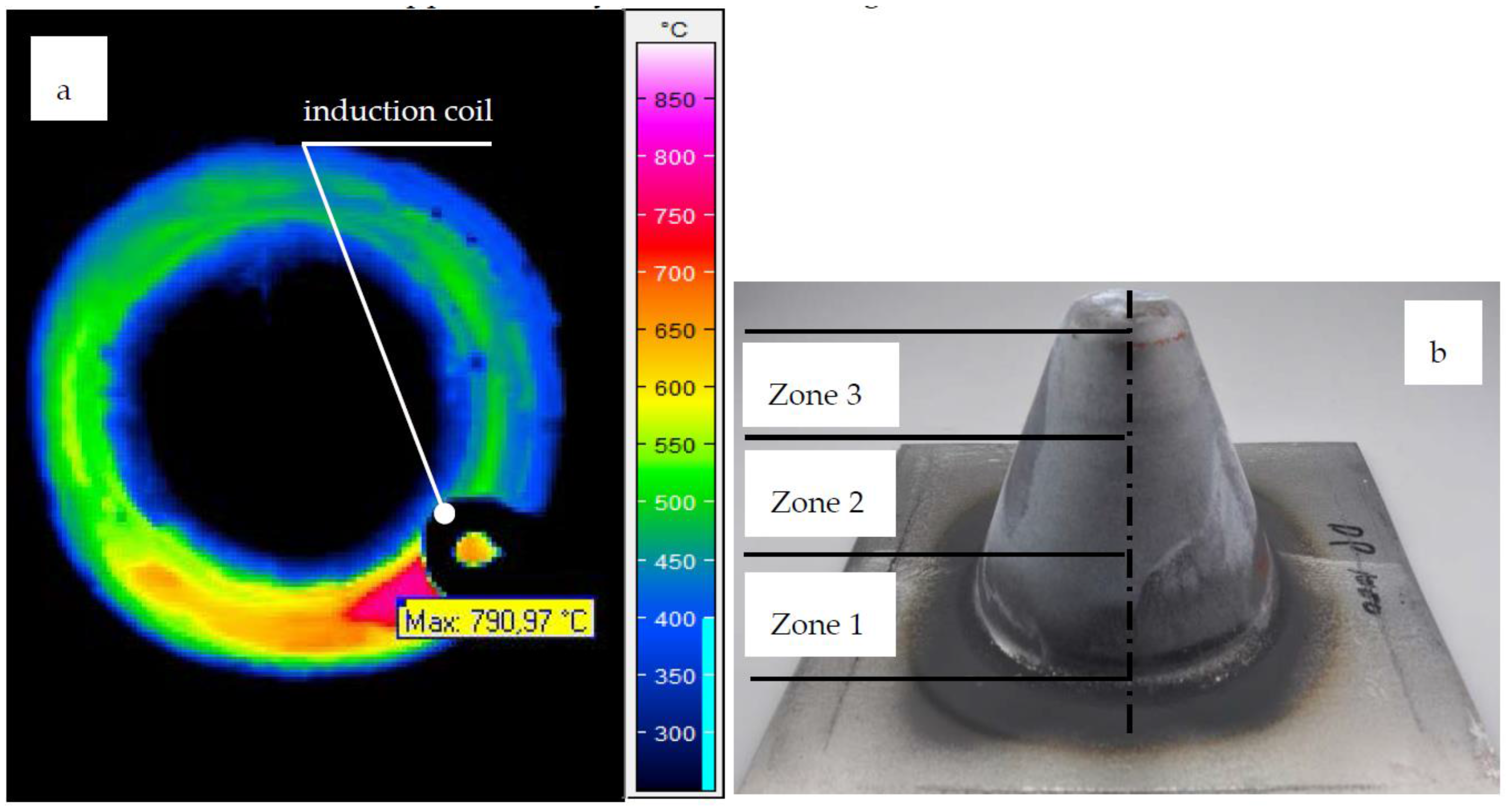
The maximum tensile strength of HCT980C steel as delivered was 1000 MPa, but after forming at a feed rate of 1.5 m/min and using an induction power of 12.5 kW, the resulting tensile strength decreased to approximately 540 MPa. The obtained tensile strength after forming was extracted from a tensile test sample that was described in
Section 2.2.
The HCT980C tensile strength was significantly influenced when heated to more than 750 °C as investigated by [
17]. The sample temperature reached 790 °C when formed at a feed rate of 1.5 m/min and using an induction power of 12.5 kW as shown in
Figure 7a. At the same time, the formed cone was divided into 3 equal zones as shown in
Figure 7b, and the microhardness values of each zone were found different from the neighbouring zone. Furthermore, the total cone height was 70 mm, therefore, each zone was approximately 23.33 mm in length.
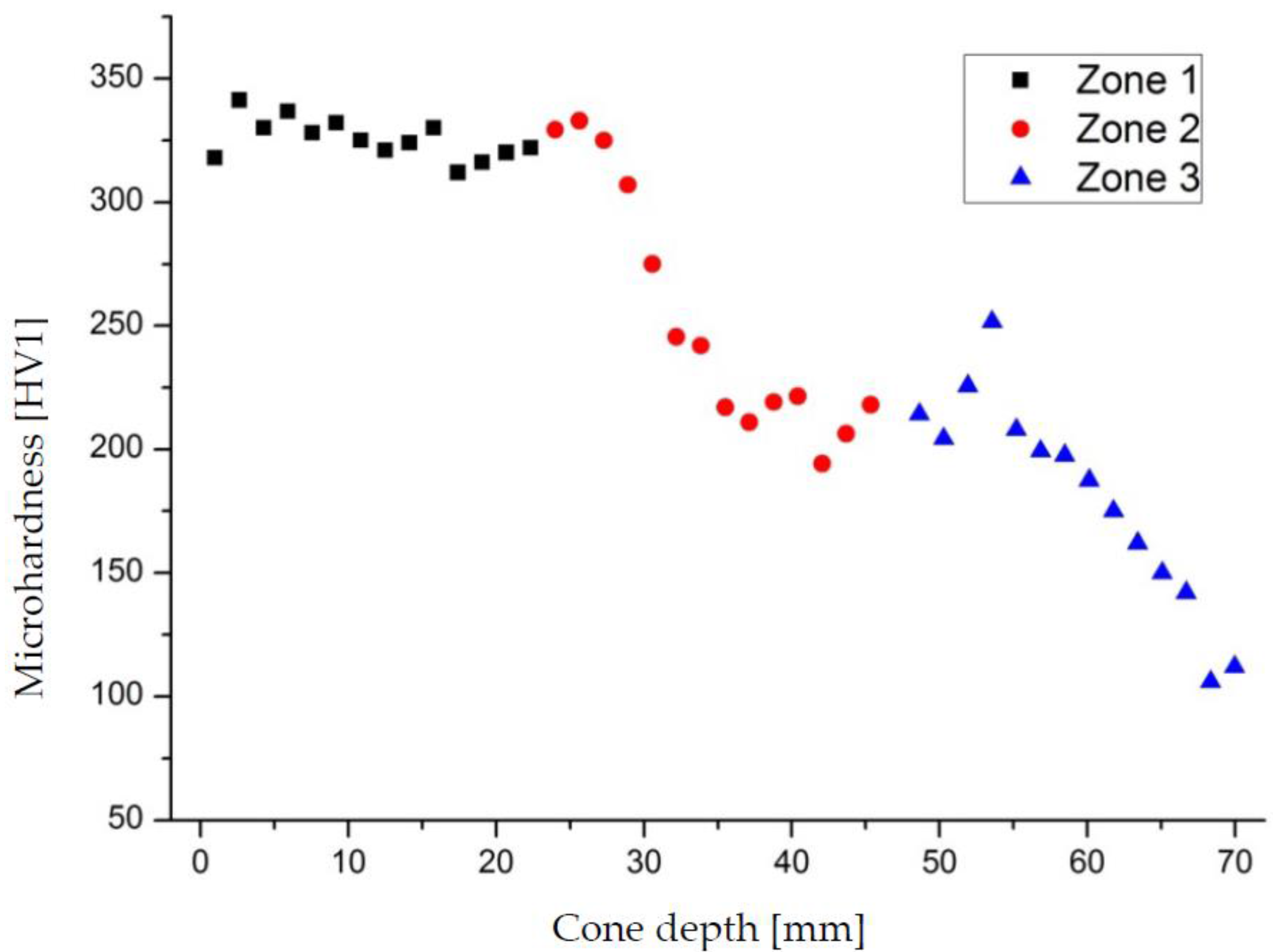
As indicated in
Figure 8, the minimum microhardness was observed in the third zone due to the reduction of the cone diameter during forming. It appears that heat dissipated more so in the large cone area and was generated more so in the smaller cone area.
Figure 8 indicates that the minimum microhardness values were located in the upper end of the smaller cone area. In addition, in the smaller cone area the microhardness reached 106 HV1. The as-delivered microhardness of HCT980C steel is 340 HV1, which corresponds to the area that is located in the first zone.
A very large difference in mechanical properties between the as-delivered and the hot-formed metal has been observed. This phenomenon was also reported in [
18] (p. 218), where the author stated that the microhardness of the DC01 steel decreased after hot forming.
3.4. Applying a New Forming Technique
Most researchers who studied hot incremental forming have suggested a constant feed rate during forming and controlled the increase in heat by methods, such as those in [
19], which require large and expensive components.
In this work, the effect of induction heating during forming of HCT980C steel was observed to reduce the tensile strength and microhardness of the formed part. Therefore, it is necessary to find a new technique to improve the tensile strength and microhardness for the produced part.
3.4.1. New Forming Technique
The new forming technique is done by forming at a varied feed rate instead of forming at a constant feed rate. In our experiment, the depth of the formed cone was 50 mm and it was divided into eight sections. The feed rate changed from 1.5 to 4.125 m/min as demonstrated in
Table 1 below.
The feed rate was changed in the CNC milling machine code program by writing the suitable feed rate for each depth in the z-direction. A large number of feed rates were investigated during initial experiments. This technique depends on changing the feed rate with cone depth during on-line forming operations, which also serves to control the heat distribution in the formed part shape. The optimum feed rates as stated in
Table 1 were selected carefully according to the resulting mechanical properties of the formed part as described in the next section.
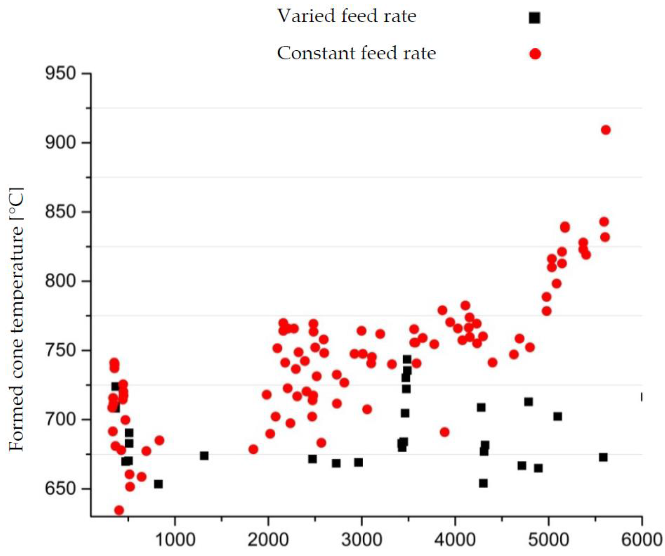
3.4.2. Effect of the New Technique on Heating Temperature
Using the feed rates in
Table 1, the heat distribution over the entire cone profile was shown to be homogenous. The measured temperature for the new technique that uses a variable feed rate is compared to the temperature for the constant feed rate in
Figure 9.
We also observed that when forming with a constant feed rate, the heating temperature increased from 625 °C to more than 900 °C from the beginning to the end of the process. When applying the new technique, the temperature was between 650 °C to 750 °C during the entire forming operation. The mechanical properties obtained from the tensile samples after 20 min of soaking as stated in
Section 2.1 were not like those obtained from the instantaneous sheet heating by induction synchronized with SPIF.
3.4.3. Influence of the New Technique on Formed Part Properties
The tensile strength of the produced parts when forming with the new technique was between 880 to 690 MPa, which is much better than those listed previously in
Section 3.3. At the same time, the obtained microhardness was increased in a homogenous distribution between 270 to 330 HV1 for all zones in the cone depth.
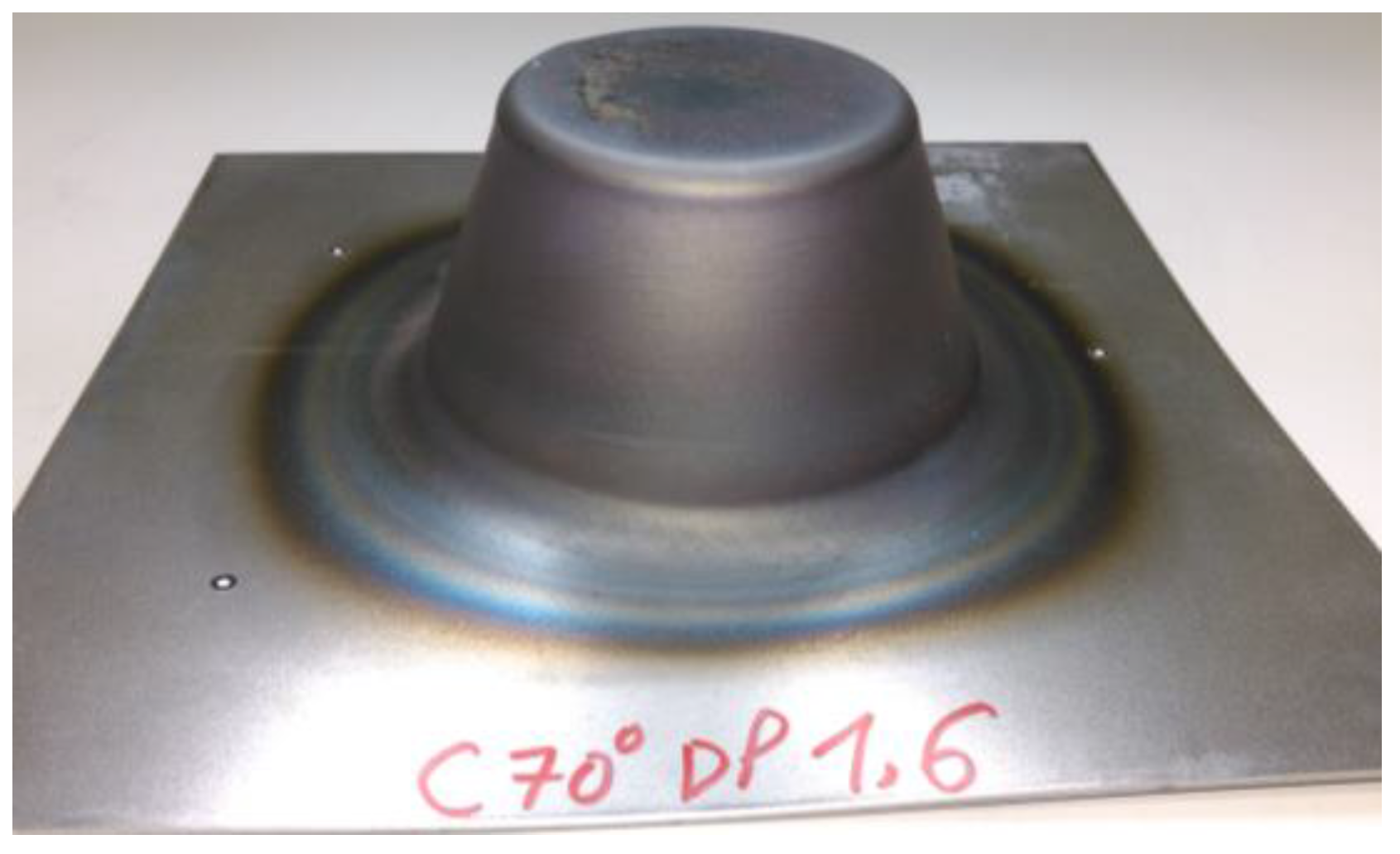
3.5. Improving the Formability
The findings of this investigation indicate the capability to form cone wall angles of 70° in HCT980C steel when using a varied feed rate, as shown in
Figure 10. The formed 70° wall angle was accomplished by using an 8 mm tool tip diameter.
4. Conclusions and Outlook
A cone shape in HCT980C steel was accomplished using SPIF assisted by induction heating. The geometrical accuracy was enhanced by varying the feed rate and increasing the induction power.
The forming force generated during induction heating was reduced to 1850 N from 5500 N that was generated during forming at room temperature.
This investigation proposed a method to form the AHSS aided by induction heating, but disadvantages due to excessive heating rates were observed. The excessive heating rates caused an increase in ductility and reduction in the hardness of the formed part. However, a smart solution was introduced to solve the ductility and hardness problem by forming at a variable feed rate ranging from 1.5 to 4.125 m/s. The difference in heating temperature at the beginning and the end of forming time in constant feed rate was 275 °C. However, by applying the new method, the difference from the beginning to the end of the forming time was less than 100 °C. The formability of HCT980C steel was demonstrated by forming a part with a 70° wall angle.
Future investigations could include heating the sheet up to 900 °C and performing a quenching operation to increase the hardness during forming. This can be done by using a quenchable steel to make a tailored part of different strength zones.


