1. Introduction
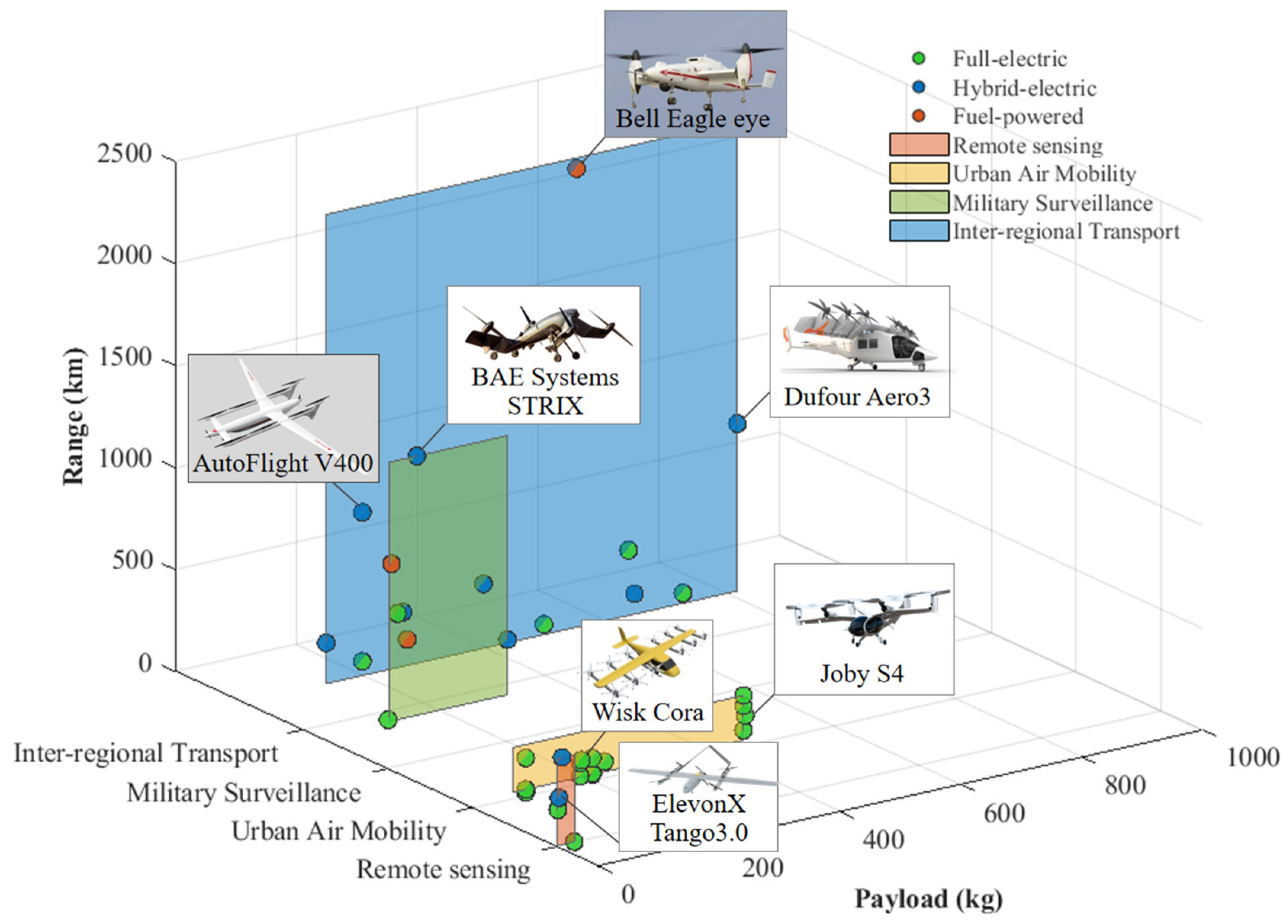
Unmanned vertical takeoff and landing (VTOL) aircraft, prized for their runway-independent operation, are increasingly applied in civilian sectors, such as remote sensing and transportation, and in military missions, including island reconnaissance and surveillance [
1]. Traditional internal combustion engines (ICEs) perform inefficiently due to the large power gap between takeoff and cruise [
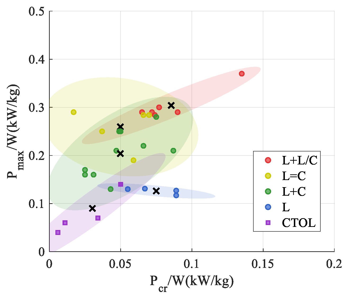
2,
3]. For instance, the Wisk Cora eVTOL operates at 20% cruise power relative to maximum takeoff power, below the 25–40% typical of conventional ICE aircraft. This disparity arises from its dual aerodynamic constraints: takeoff thrust-to-weight ratios exceeding those of fixed-wing platforms, combined with cruise lift-to-drag efficiency surpassing those of helicopters. Although full-electric (FE) propulsion can be adopted to various load conditions, its application is restricted by battery energy density, restricting long-range endurance [
4]. In contrast, hybrid-electric systems offer flexibility by varying the distribution between power and energy source [
5]. Nevertheless, designing VTOL power systems remains complex due to multi-condition constraints, strong nonlinear coupling among variables, and diverse optimization objectives—necessitating precise parameter matching for effective performance optimization.
Researchers have developed a range of design methodologies and modeling frameworks to develop VTOL aircraft design solutions. Early-stage sizing and integration have been supported by frameworks aided by researchers, such as Chakraborty and Finger [
6,
7]. Additionally, conventional aircraft design platforms have been adapted for VTOL-specific applications, such as NASA’s OpenAeroVTOL and Seoul National University’s RISPECR+ [
8]. These advancements have accelerated productization, leading to the entry of several FE VTOLs into commercial service. Autoflight recently demonstrated a 250 km flight test, marking a key milestone in VTOL range capability [
9,
10]. To address the increasing demands for longer-range and heavier payloads, hybrid-electric (HE) VTOL platforms are being actively developed. The NASA Greased Lightning project demonstrates the viability of HE VTOL, showcasing a diesel-battery hybrid propulsion system [
5,
11]. Several small-scale hybrid VTOL prototypes have already completed bench and flight tests [
12,
13,
14]. Meanwhile, hydrogen-electric VTOLs are rapidly progressing, with the Joby SHy4 achieving an 840 km flight test in 2024 [
15,
16].
Recent studies have increasingly focused on design optimization methodologies, focusing on multidisciplinary optimization at design points and energy management strategies under off-design conditions [
17,
18,
19,
20,
21]. Advanced algorithms, including genetic algorithms [
18,
22,
23] and AI-driven optimization [
24,
25], are being integrated into VTOL propulsion design [
26]. However, systematic methodologies for evaluating and selecting optimal VTOL powertrain configurations remain underdeveloped. The current methods often rely on oversimplified models or fixed configurations, potentially resulting in suboptimal efficiency and performance. As the design progresses through refinement, modification costs increase exponentially, necessitating comprehensive design space exploration during initial development phases.
Previous studies have laid the groundwork for HE aircraft sizing. Nam [
27] introduced a power–energy-based aircraft sizing approach, moving from traditional thrust–fuel matching to power–energy matching, and established the theoretical foundation for multi-energy power system parameter design. Vries [
28] proposed the power ratio (HP) to quantify power distribution in HE aircraft systems, realizing range estimation for various power architectures despite lacking power architecture and control strategy information; however, it overlooked power demand variations across flight phases. Isikveren and Lampl later incorporated both power ratios (HP) and energy (HE) ratios to model all types of powertrain configurations and estimate propulsion system weight and size, though their approach neglected the inner relationships between HP and HE [
29,
30]. To address this issue, Harish developed a matrix-based framework linking energy, power, and thrust sources; preserved the connectivity characteristics between diverse sources; and achieved higher fidelity to real-world hardware implementations [
31,
32]. While these methods apply to the multi-condition constraints of parameter-coupled preliminary design of VTOLs, there is a critical gap between theoretical formulations and physical implementations.
Building on Harish’s matrix-based approach, this study introduces a propulsion system sizing method tailored to VTOL aircraft, offering a scalable approach to accelerate early-stage decision-making. The main contributions are summarized as follows:
(i) By integrating real-world application scenarios and incorporating commercial Off-the-Shelf (COTS) products and data sources, this methodology bridges the gap between theoretical frameworks and physical implementations, demonstrating its viability in engineering practice.
(ii) A universal parametric configuration is defined, and corresponding range equations are derived for various powertrain configurations. Through full-factorial decomposition, key independent matching parameters are identified, simplifying the design process and enabling efficient navigation of the VTOL powertrain design space, reducing computational costs and accelerating design iterations.
(iii) Through power–energy matching parameter analysis, configuration selection and optimization principles are established for diverse mission scenarios and technological conditions, guiding component-level technology advancements.
2. Powertrain Matching Design Approach
As shown in
Figure 1, the VTOL aircraft design process typically consists of four iterative components: power requirement analysis, propulsion system sizing, mission analysis, and total weight calculation [
17]. Power analysis translates top-level design goals into propulsion design requirements. The propulsion system sizing and mission analysis process guarantees matching power and energy supply with demand. Finally, the design process concludes with total weight verification to validate the overall design outcomes. Due to the integration of multiple energy sources, hybrid powertrain systems exhibit greater design flexibility in power and energy matching compared to conventional powertrains. To enable rapid convergence of diverse architectural solutions, a novel power–energy matching method is introduced. Through the full-factor decomposition of the range equation, the factors influencing platform range–payload performance are thoroughly considered. The first-level decomposition yields key parameters including the overall efficiency
, lift-to-drag ratio
, specific fuel energy
, and platform initial-to-final mass ratio
. This mass ratio can be further decomposed into subsystem mass fractions, specifically empty weight fraction
, payload fraction
, power system weight fraction
, and residual fuel fraction
. Three independent key matching parameters are extracted: the power ratio (Φ), energy ratio (Ω), and maximum continuous discharge rate (rc). A sensitivity analysis of these parameters against predefined performance metrics is conducted to derive matching principles. These insights are then applied to guide the determination of power and energy matching parameters, such as optimal battery power distribution under various operating conditions.
The proposed method offers several advantages. It unifies diverse propulsion configurations within a universal power system parametric model, enabling cross-architectural comparisons among FE, ICE-powered, and HE configurations, while quantitatively delineating the operational superiority boundaries of each powertrain topology. The extracted key matching parameters uniquely characterize corresponding powertrain configurations through mutually orthogonal variables. Benefiting from low parametric dimensionality, this formulation enables cost-efficient exhaustive exploration of the entire design space, thereby propelling preliminary design iterations into neighborhoods of optimal solutions.
2.1. Universal Propulsion System Configuration
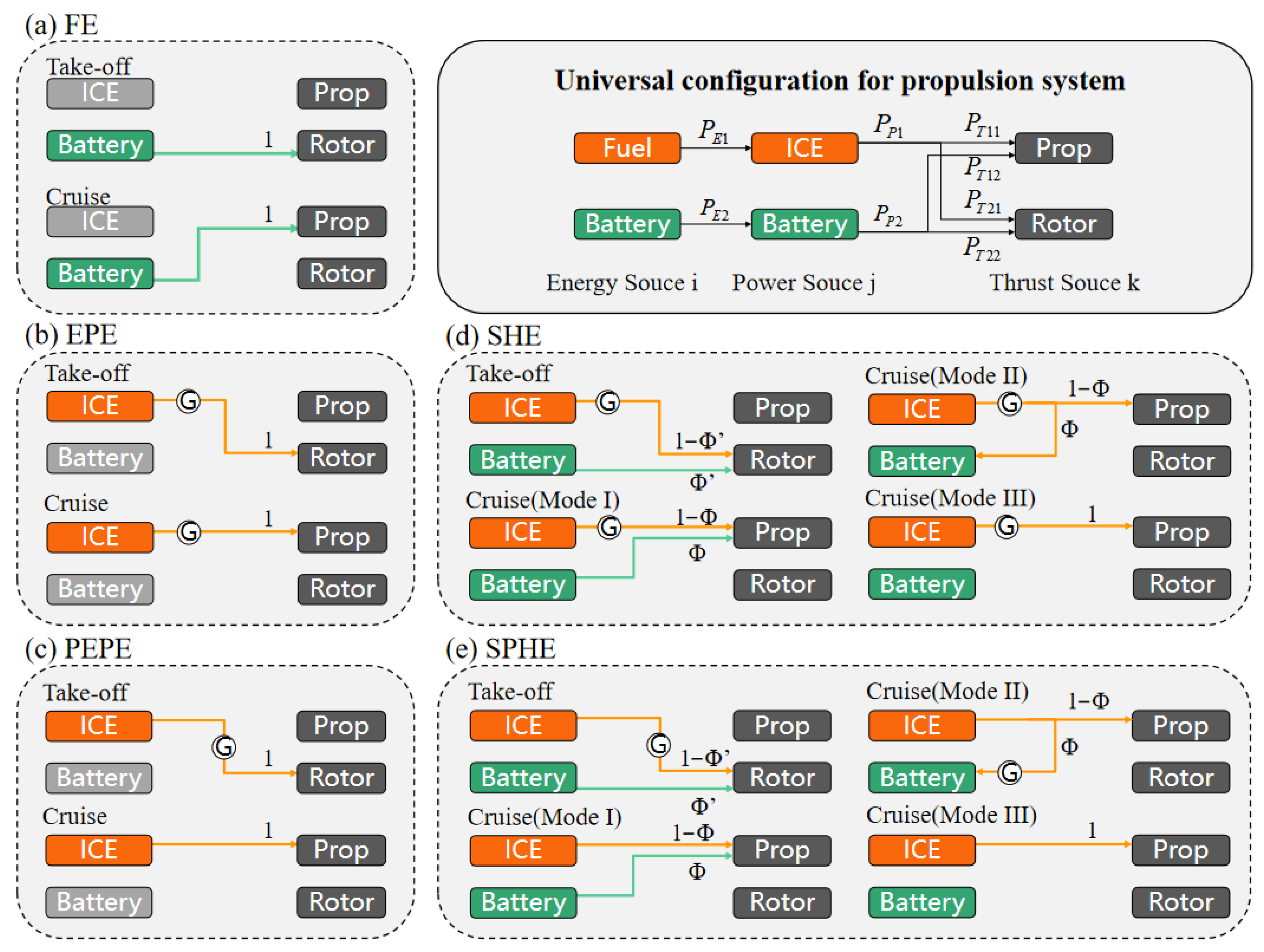
A universal power system configuration is introduced for propulsion system sizing, which can describe various propulsion configurations and their operating modes in a parametric framework (
Figure 2) [
33]. The propulsion configuration can be characterized by five matrices:
(energy distribution matrix),
(energy-to-power source transfer matrix),
(power-to-thrust source transfer matrix),
(power allocation matrix), and
(efficiency chain matrix for propulsion power generation).
The definitions of the five matrices are as follows:
where
signifies power from the energy source ‘
i’,
implies power from the power source ‘
j’, and
denotes the thrust source ‘
j’. For VTOL aircraft, the distributed arrangement of propulsion systems enables multiple configurations, including FE (full-electric), EPE (engine-powered electric), PEPE (partial engine-powered electric), SHE (series hybrid-electric), and SPHE (series-parallel hybrid-electric) configurations.
Figure 2 presents their corresponding topologies across different operational modes. We define the power ratio Φ of the battery in the cruise phase and the power ratio Φ’ at the takeoff point. For Φ > 0, the battery and generator jointly power the propulsor, representing Mode I in
Figure 2; when Φ < 0, the generator powers the propulsor while charging the battery, denoting Mode II. Φ = 0 indicates all generator power is directed to the propulsor, representing Mode III.
The power ratio Φ is the ratio of the battery power
to the sum of the battery power and the generated power
.
Under the assumption of constant generator power output, Φ′ at takeoff is derived as a function of Φ and is given by
where
and
refer to the cruising and maximum power requirement of the VTOL platform.
,
, and
refer to the efficiency of the electric system, generator, and planetary gear mechanism separately.
2.2. Range Equations of Each Configuration
As defined by Seitz [
34], the total range can be derived from the integrated incremental flight distance per energy consumption, as shown in Equation (8). Following Seitz’s method, the overall system efficiency
is defined in Equation (9) [
31].
is the weight of the platform.
For FE configurations, the weight of the platform remains constant during flight, enabling its removal from the integral and resulting in Equation (10) [
32], where
signifies the equivalent battery weight fraction of cruise energy, as defined in Equation (11), which can be derived from empty weight fraction
, payload fraction
, and residual battery weight fraction
.
For HE configurations, the fuel consumption leads to in-flight weight variation, necessitating the integration of weight into range calculations, with energy terms expressed by weight differentials in Equation (12) [
31,
32]. We consider the SHE configuration as an example. Assuming that
and Φ remain constant during cruising, the cruise-phase fuel energy ratio
can be expressed as Equation (13). The initial-to-final weight fraction of the platform
during the cruise phasecan be derived from
,
, power system weight
, and residual fuel fraction
, as shown in Equation (14).
Table 1 presents the derived range equations and power system weight
for each configuration. The symbols
,
, and
represent the efficiencies of the propulsive, battery, and engine, respectively, where
,
, and
signify the weight of the power management system, fuel-based auxiliary power generation unit, and planetary gear mechanism, respectively.
2.3. Matching Parameter Extraction
Based on the preceding series of formula derivations, the relationship between range and weight can be ascertained. However, directly exploring the design space using component-level inputs becomes computationally expensive and inefficient. To achieve global optimization, the hybrid power system model necessitates a balance between computational cost and precision, ensuring comprehensive design space coverage within finite computational resources. This challenge can be addressed through systematic coupling analysis between component parameters and range equations to identify key design freedoms, extract the independent, physically meaningful matching parameters, which can serve as effective control variables for design space exploration while maintaining physical interpretability.
The analysis focuses on the SHE configuration. In Equation (14), the initial-to-final weight ratio enables estimation of the empty weight fraction using statistical data, while the payload, power system, and residual fuel fractions are derived analytically. According to the power–energy matching process shown in
Figure 1, three fundamental matching parameters were defined to determine the component weight fraction: (1) power ratio (Φ); (2) energy ratio (Ω), representing the proportion of battery energy
in the total input energy from the battery and generator at the propulsion system input node; and (3) maximum continuous discharge rate (rc).
The power system can be decomposed into the power management system (PMS) and fuel-based auxiliary power generation unit (APU), which are defined by Equations (16) and (17), respectively.
The weight ratio of the battery and fuel can be derived by Ω as in Equations (18) and (19).
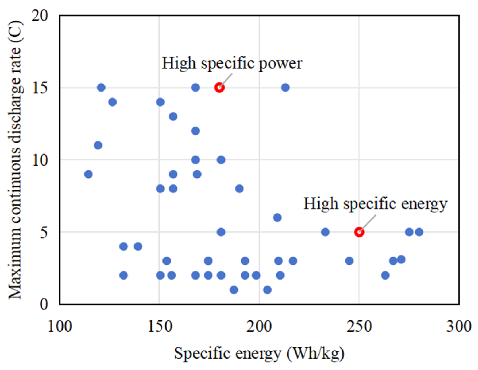
Three constraints are applied to the energy system to ensure compliance with platform performance requirements. The battery weight ratio is restricted by takeoff capacity, which is relative to the maximum continuous discharge rate (rc) of the battery. Residual battery and fuel weight must satisfy takeoff and landing energy constraints under continuous maximum power operation during these phases.
Once subsystem weight fractions are defined, the range can be calculated. This approach fundamentally applies to all powertrain configurations, since their architectural differences are fully characterized by linear mappings within the Φ-Ω-rc parameter space. Specifically, the FE configuration represents the singular case where Φ = Ω =1. The extracted matching parameters effectively decouple interdependencies among variables, allowing independent tuning of key design factors and improving optimization stability.
5. Conclusions and Outlook
This study presents a novel configuration trade-off and optimization framework for VTOL aircraft. The configuration selection guidelines and optimization outcomes are derived for a range of mission scenarios. Finally, the proposed method was validated using VTOL platforms representing different aircraft classes. The key findings are summarized as follows:
(1) The minimum MTOM configuration distributions derived for a 1000 km range and 500 kg payload indicate distinct applicability zones. The SPHE configurations are well-suited for medium–long-range missions (200–1000 km), while the SHE and EPE configurations dominate short-range operations (0–200 km). FE configurations are optimal for ultra-short-range scenarios (0–40 km). To enable the electrification of long-range, heavy-duty missions, coordinated advancements in both battery and combustion technologies are essential, supporting a dual-path optimization strategy.
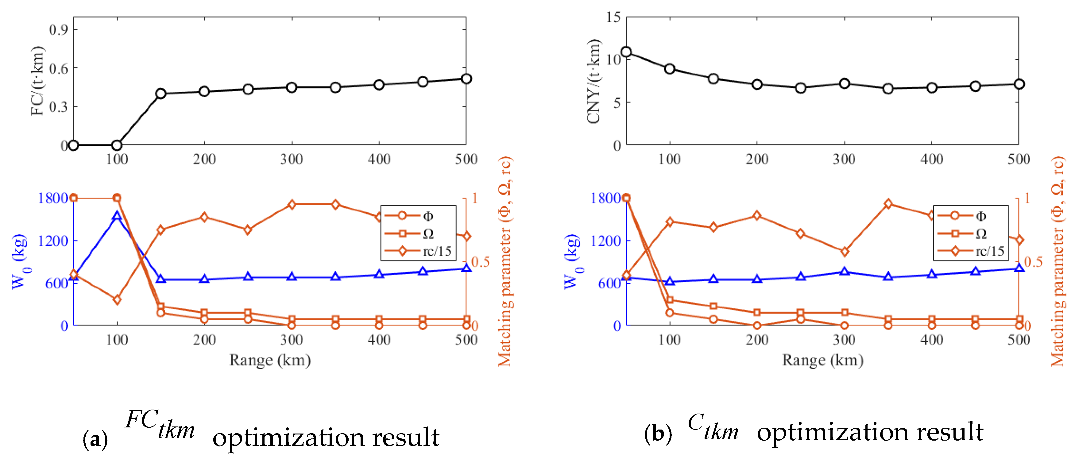
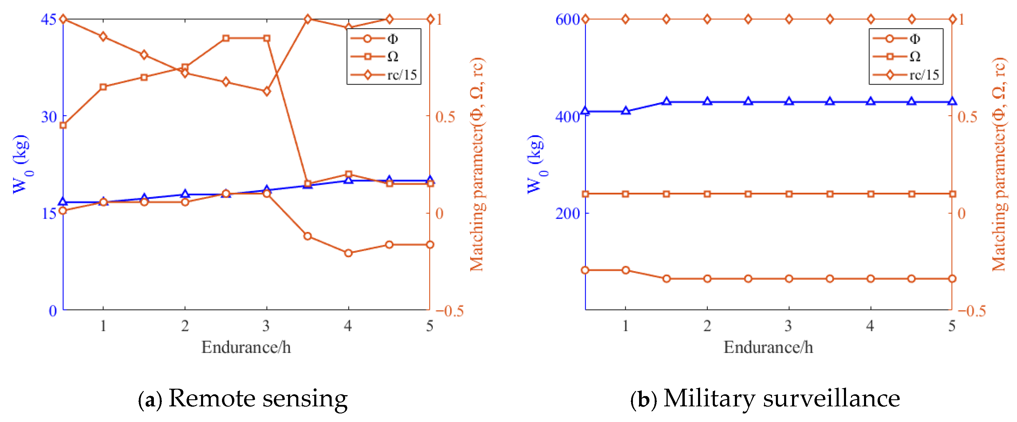
(2) Configuration optimizations were conducted across two distinct operational scenarios using tailored evaluation metrics. In transportation applications, 100 km serves as the current threshold between the FE and SHE configurations. For missions below 100 km, FE configurations provide superior cost and efficiency. Beyond this threshold, the SHE configurations become more favorable due to their improved energy management capabilities. In military surveillance missions, where high-altitude operations impose substantial power demands during climb and cruise, the engine must provide power slightly exceeding cruise requirements to enable in-flight battery charging.
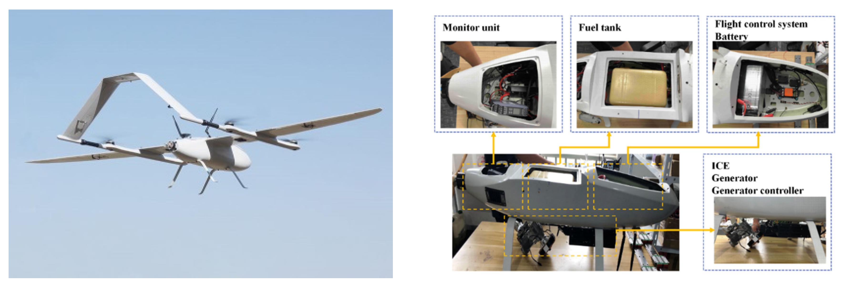
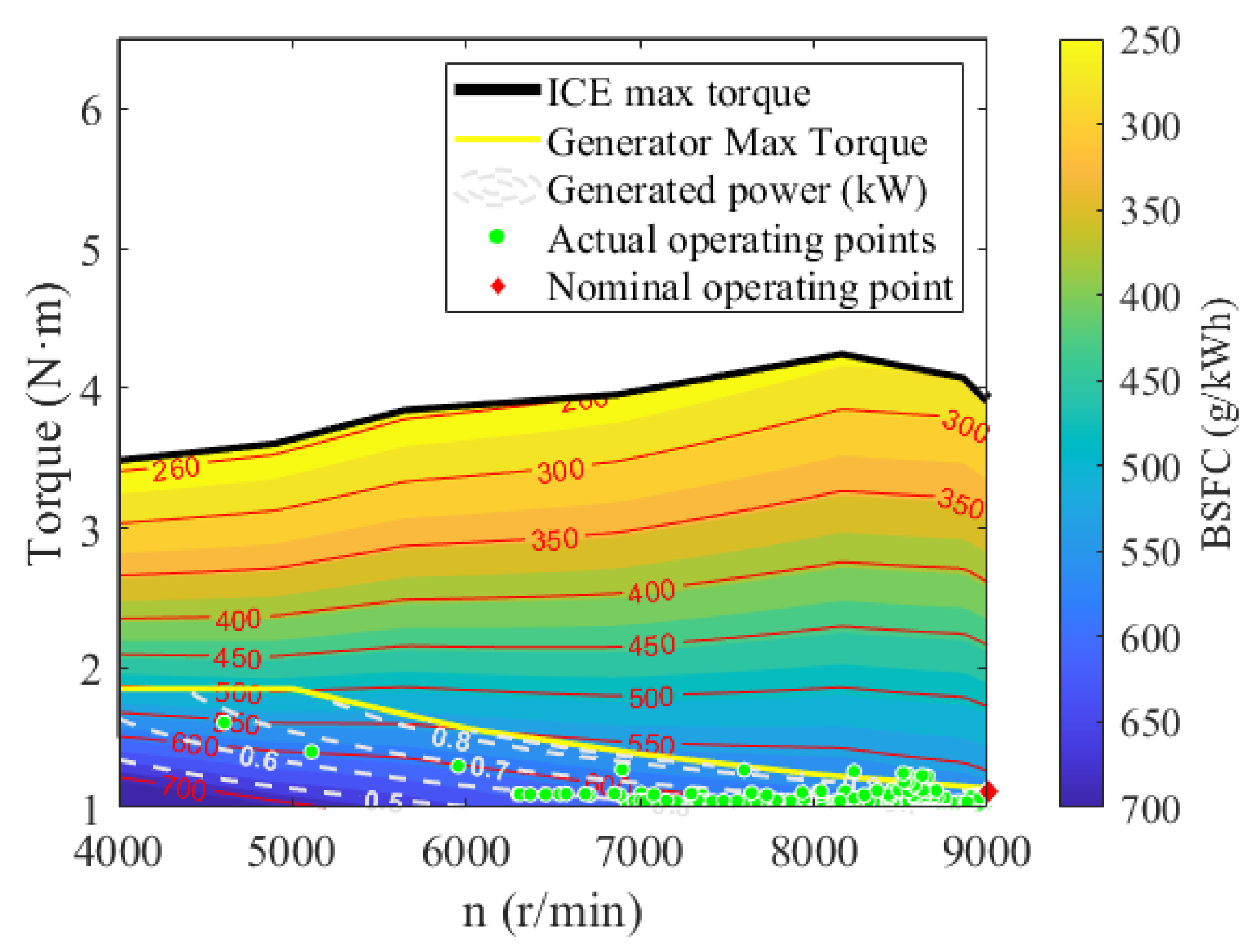
(3) The retrofit process of the Great White eVTOL power system demonstrated the practical engineering value of the proposed method. Based on the subsystem steady-state characteristics and the overall dynamic behavior of the platform, the design scheme was progressively refined. Following the preceding corrections, the configuration was iteratively optimized, resulting in a 10.49% increase in cost per ton-kilometer compared with the initial design. These results confirm that the proposed co-design methodology provides a scalable, data-driven foundation for early-stage hybrid-electric VTOL powertrain design, enabling iterative performance correction and supporting system optimization across future design and validation phases.
While the current model includes necessary simplifications of physical realities, it serves as a robust foundation for architectural assessment and optimization. Three primary extension pathways emerge: (1) Model refinement through the integration of off-design effects, such as power–energy density coupling in batteries and thermo-mechanical coupling in hybrid powerplants. (2) Incorporation of environmental coupling factors, including altitude-dependent performance degradation and the influence of atmospheric condition effects. (3) Expansion of applicability to a broader range of VTOL application scenarios and next-generation propulsion systems, including fuel cell-electric and hydrogen-combustion systems. These enhancements would bridge the gap between conceptual design optimization and real-world operational performance.

