Article

Secure Energy Efficiency Maximization for IRS-Assisted UAV Communication: Joint Beamforming Design and Trajectory Optimization

College of Intelligent Systems Science and Engineering, Harbin Engineering University, Harbin 150001, China
*
Author to whom correspondence should be addressed.
Drones 2025, 9(9), 648; https://doi.org/10.3390/drones9090648
Submission received: 16 August 2025 / Revised: 6 September 2025 / Accepted: 12 September 2025 / Published: 15 September 2025
(This article belongs to the Section Drone Communications)

Abstract

Highlights

What are the main findings?
  • An optimization algorithm is developed to enhance the security and energy efficiency of IRS–UAV communication by jointly optimizing active beamforming, IRS phase shift, and UAV trajectory.
  • The Riemannian manifold optimization approach reduces the computational complexity of solving for IRS phase shifts.
What is the implication of the main finding?
  • The proposed algorithm offers theoretical support for efficient UAV communication deployment in highly obstructed urban environments.
  • It provides a practical solution for achieving secure and energy-efficient aerial communications in complex scenarios.

Abstract

This paper addresses secure transmission in a high-occlusion urban environment, where an intelligent reflecting surface (IRS)-assisted unmanned aerial vehicle (UAV) communication system serves a legitimate user while countering an eavesdropper. The UAV signal is reflected to the base station through the IRS. We study the secure energy efficiency optimization problem. The tightly coupled optimization variables make the problem difficult to solve directly. Therefore, we decompose the original problem into three sub-problems. For the UAV active beamforming design, the closed-form solution can be obtained directly. For the IRS phase shift optimization, we propose an optimization algorithm based on Riemannian manifolds to obtain the optimal solution. Due to the non-convex fractional UAV trajectory optimization, it can be solved by successive convex approximation (SCA) and the Dinkelbach algorithm. Different comparison schemes are designed to evaluate the effectiveness of the proposed algorithm. The simulation results show that the proposed algorithm has improved advantages compared with other schemes.

1. Introduction

Current research on the sixth-generation (6G) mobile communication technology has entered a phase of comprehensive exploration, signifying the advent of a new era in mobile communication [1]. Beyond extending existing functionalities, 6G will serve as a nexus between the physical and digital worlds, enabling ubiquitous interconnectivity [2]. Within this context, unmanned aerial vehicle (UAV) communication, as a critical branch of wireless communication, will play a pivotal role in the 6G system, advancing the realization of true perception, interconnection, and intelligence of all things [3,4]. Leveraging exceptional flexibility and cost-effectiveness, the UAV communication system enables rapid deployment to address emergency scenarios, fulfill temporary communication demands, and provide capacity enhancement and coverage extension in high-traffic hotspots [5]. As a core component of the aerial platform with 6G integrated space–air–ground–sea network architecture, UAV communication will contribute significantly to building a globally accessible, high-speed, and intelligent communication system [6,7]. With the continuous evolution of 6G technology, the UAV communication system will further enhance its coverage capability and service quality, providing robust technical support for realizing the grand blueprint of societal development characterized by “Inclusive Intelligence and Digital Twins” [8].
A key vision for 6G development is to facilitate the growth of smart city clusters, creating a unified network with seamless coverage and connectivity spanning air, space, land, and sea [9]. UAV communication, as a vital component of the air-based network, faces significant challenges in complex urban environments characterized by high levels of obstruction. Communication links between UAVs and ground stations are frequently blocked by high-rise buildings and other large structures, leading to degraded performance or complete link failure [10]. This limitation hampers the efficiency and reliability of UAV communication in tasks such as data transmission and surveillance.
To address this issue, an intelligent reflecting surface (IRS) has been introduced into the UAV communication system. An IRS, comprising an array of controllable reflective elements, manipulates the amplitude and phase of incident signals. This capability enables the physical-layer enhancement of the wireless signal propagation environment, thereby improving signal transmission effectiveness. IRSs can be deployed on UAVs or building façades. By precisely controlling the phase and amplitude of each reflecting element, the IRS achieves intelligent signal reflection and beamforming. This directs signals towards areas that were previously unreachable due to building blockages, enhancing communication quality between UAVs and ground users.
As shown in Figure 1, the signal from the UAV is reflected by the IRS to the BS. The system’s performance is maximized through the joint optimization of active beamforming, the IRS phase shift, and the UAV’s flight trajectory. Firstly, UAV trajectory optimization must consider not only flight efficiency and energy consumption but also ensure communication link stability and broad coverage. Secondly, wireless resource allocation is another critical factor for system performance optimization. Within an IRS-assisted UAV system, controlling the phase shift and amplitude of incident signals allows for beamforming of wireless signals through the constructive superposition of the direct and reflected signals. This enhances the received signal strength and boosts overall communication performance.
IRS-assisted UAV communication system faces significant challenges. The introduction of the IRS increases system complexity, necessitating rational resource allocation to achieve optimal communication performance. Crucially, the phase configuration of the IRS and the UAV trajectory are mutually coupled. This interdependence makes real-time resource allocation and trajectory optimization a key challenge [11].
Refs. [12,13,14] focus on enhancing the system sum rate or average rate through joint optimization. In [12], a UAV–IRS-aided MISO-NOMA downlink is proposed; the strong user’s rate is pushed to the limit by simultaneously optimizing the UAV–IRS placement, transmit beamforming, and reflective phases. Ref. [13] studies a symbiotic UAV–IRS architecture where IRS scheduling, phase configuration, and UAV trajectory are jointly tuned to maximize the IRS’s own data throughput. Ref. [14] further considers an IRS-supported aerial link and lifts the average rate by co-designing passive IRS beamforming and the UAV flight path. Refs. [15,16,17,18] concentrate on boosting the secrecy rate in the presence of eavesdroppers. Specifically, ref. [15] studies IRS-enhanced UAV communication under jamming, the confidential rate is maximized by jointly tuning ground transmit power, IRS phase shift, and UAV trajectory. Likewise, ref. [16] addresses an IRS–UAV network threatened by an eavesdropper, where active UAV beamforming, passive IRS beamforming, and 3D flight path are simultaneously optimized to achieve the highest average secrecy throughput. Ref. [17] proposes an IRS-assisted covert communication system that utilizes a friendly UAV to emit artificial noise to interfere with the eavesdropper and maximizes the covert rate by jointly optimizing IRS phase shift, power allocation, and UAV trajectory. Ref. [18] studies an IRS-assisted ground-to-air communication network and assumes that the height of the UAV is not fixed. By jointly optimizing the transmission power, active beamforming, passive beamforming, and the UAV three-dimensional trajectory, the average secure rate is maximized.
In the IRS-assisted UAV communication system, the energy supply is limited, and the UAV requires a large amount of energy during operation, making energy planning an urgent problem to be solved. It is particularly necessary to improve energy efficiency by optimizing resource allocation and UAV trajectory [19]. Ref. [20] presents a communication system that integrates an IRS into UAVs. By jointly optimizing active beamforming, passive beamforming, and UAV trajectory, the system’s spectrum and energy efficiency are improved. Ref. [21] presents research on secure energy efficiency optimization while countering an eavesdropper. The authors aim to maximize secure energy efficiency by optimizing UAV active beamforming, IRS phase shift, and UAV trajectory.
The existing research in optimization of IRS passive beamforming mainly relies on semidefinite relaxation (SDR) or other approximation methods. These methods require relaxing the discrete phase shift constraints into a higher-dimensional semidefinite matrix space for solution. Subsequently, a complex projection operation, which may incur performance loss, is necessary to enforce the original constraints. This significantly increases the computational burden, particularly limiting efficiency for large-scale IRS scenarios. To address this, the proposed Riemannian manifold optimization algorithm offers core advantages: it directly models the phase shift of each IRS reflecting element as a point on the complex circle manifold. Consequently, the entire IRS phase shift matrix naturally forms a specific Riemannian manifold structure. The algorithm performs optimization iterations (such as the conjugate gradient method) directly on this geometric structure. Crucially, the iterative update rules on the manifold efficiently maintain the solution within the feasible region. Compared with traditional relaxation methods (such as semidefinite relaxation), Riemannian manifold optimization eliminates the need for introducing additional relaxation variables or performing dimensionality augmentation operations, while also avoiding the rank-1 solution recovery issue that may arise after relaxation. By conducting an efficient search directly on the high-dimensional nonlinear constrained manifold, it significantly reduces computational complexity.
The main contributions of this paper can be categorized as follows:
  • We propose an IRS-assisted UAV communication system for city environments with high occlusion while countering an eavesdropper. The direct link between the UAV and the base station is interrupted due to obstruction by a high-rise building. The IRS is deployed to reflect the UAV signal to the base station. Then, we demonstrate a system communication channel model and formulate a secure energy efficiency problem.
  • The secure energy efficiency optimization problem is solved by jointly optimizing UAV active beamforming, IRS passive beamforming, and UAV trajectory. In addition, for the IRS passive beamforming optimization, we propose a Riemannian-manifold-based optimization algorithm to reduce computational complexity. Subsequently, by using successive convex approximation (SCA) and the Dinkelbach algorithm, the UAV trajectory optimization problem is solved.
  • Simulation results demonstrate the effectiveness of the proposed model and algorithm. We set up two comparison schemes: one without an IRS and one with a random phase shift. The simulation results show that the performance of the proposed model and algorithm is superior to the above two schemes, thus verifying the importance of deploying IRSs and dynamically optimizing passive beamforming.
The remaining structure of the paper is arranged as follows:
Section 2 develops the system model and formulates the secure energy efficiency problem. Section 3 presents the procedure of the proposed algorithm. Section 4 obtains and analyzes the simulation results. Section 5 concludes this paper.

2. System Model and Problem Formulation

2.1. System Model

As shown in Figure 2, this IRS-assisted UAV communication system addresses communication link disruptions in highly occluded urban environments while countering eavesdropping threats. The UAV equipped with N u antennas flies from the initial horizontal coordinate q 0 to the final horizontal coordinate q F over the flight duration T, maintaining a fixed altitude H u . The UAV maximum flight speed is V max , and the maximum acceleration is a max . To facilitate analysis and optimization, we discretize the flight duration T into N equal time slots, i.e., T = N Δ t . At each time slot n (n = 1, 2,…, N), the UAV position and velocity are denoted as q [ n ] and v [ n ] , respectively. The UAV trajectory should satisfy the following constraints:
q [ 1 ] = q 0 , q [ N ] = q F
v [ n ] V max , a [ n ] a max
q [ n ] = q [ n - 1 ] + v [ n - 1 ] Δ t + 1 2 a [ n - 1 ] Δ t 2
v [ n ] = v [ n - 1 ] + a [ n - 1 ] Δ t
The trajectory constraints of the UAV cover its common motion scenario. Equation (1) represents that the initial and end positions of the UAV are consistent with the set values. Equation (2) represents that the speed and acceleration of the UAV do not exceed their maximum values. Equations (3) and (4) are based on first-order Taylor expansion to obtain the relationship between position, velocity, and acceleration.
In urban high-blockage environments, the direct communication link between UAV and ground base station is severely blocked due to dense building obstruction, leading to frequent link interruption. To address this issue, the IRS is deployed on building façades to serve as a relay node for auxiliary communication. The IRS overcomes building-induced blockage by receiving the signal transmitted from the UAV then intelligently reflecting and beamforming it toward the base station B, in the presence of eavesdropper E. The IRS comprises a uniform planar array with M x and M z reflecting elements along x-axis and z-axis directions, respectively, yielding M = M x × M z total elements. Each reflecting element independently adjusts its phase shift to enable intelligent signal manipulation. The phase shift matrix at time slot n can be expressed as
Φ = diag e j θ 1 [ n ] , e j θ 2 [ n ] , , e j θ M [ n ] M × M
where θ m [ n ] [ 0 , 2 π ] denotes the phase shift value of m-th reflecting element during the n-th time slot. By optimizing the phase shift matrix, the IRS can dynamically steer the reflected signal toward the desired direction.
Since the UAV and the IRS are both deployed at sufficiently high altitudes, they can avoid multipath effects caused by urban high-rise buildings and signal fading on the non-line-of-sight (NLoS) path. Consequently, the communication channel can be modeled as a line-of-sight (LoS) link. Furthermore, it is assumed that the Doppler shift induced by UAV mobility is compensated. The corresponding channel model is thus characterized as follows:
H UR [ n ] = ρ d UR α [ n ] h ˜ UR [ n ] = ρ d UR α [ n ] g UR T [ n ] g Nu [ n ] M × N u
where α denotes path loss exponent, ρ is the reference channel power gain at the reference distance d = 1   m , d UR [ n ] is the distance between the UAV and the IRS, and g UR [ n ] is the uniform planar array response of the IRS receiving UAV signals, which can be expressed as
g UR [ n ] = 1 , e j 2 π λ d x sin φ u [ n ] cos ω u [ n ] , , e j 2 π λ d x M x 1 sin φ u [ n ] cos ω u [ n ] 1 , e j 2 π λ d z cos φ u [ n ] , , e j 2 π λ d z M z 1 cos φ u [ n ]
sin φ u [ n ] cos ω u [ n ] = x U [ n ] x R [ n ] d UR [ n ] , cos φ u [ n ] = H U H R d UR [ n ]
where φ u denotes the azimuth angle of arrival (AOA) from the UAV to the IRS, and ω u represents the elevation AOA at time slot n. The symbol denotes the Kronecker product.
The antenna equipped on the UAV is a uniform linear array (ULA) [22]. The response of the transmitting array can be expressed as
g N u [ n ] = 1 , e j 2 π λ d ˜ cos ϕ u [ n ] , , e j 2 π λ d ˜ N u 1 cos ϕ u [ n ]
cos ϕ u [ n ] = x R [ n ] x U [ n ] d UR [ n ]
where ϕ u is the horizontal azimuth angle.
Due to the spatial deployment characteristics between the IRS and base station B as well as the eavesdropper E, the channel is typically dominated by the LoS link. However, due to scattering from urban buildings, there also exist multiple NLoS scattering components in the signal propagation paths. This channel can be modeled as a Rician channel [23], whose mathematical representation is given by
h R i [ n ] = ρ d R i α [ n ] K K + 1 h R i LoS [ n ] + 1 K + 1 h R i NLoS [ n ] , i B , E
where d R i represents the distance from the IRS to the base station or eavesdropper, K is the Rician factor, and h R i LoS and h R i NLoS represent the LoS and NLoS parts of the channel. The LoS component can be represented by the azimuth and elevation angles from IRS to B and E:
h R i LoS [ n ] = 1 , e j 2 π λ d x sin φ u i [ n ] cos ω u i [ n ] , , e j 2 π λ d x M x 1 sin φ u i [ n ] cos ω u i [ n ] 1 , e j 2 π λ d z cos φ u i [ n ] , , e j 2 π λ d z M z 1 cos φ u i [ n ] , i B , E
sin φ u i cos ω u i = x R x i d R i , cos φ u i = H R d R i , i B , E
where φ u i and ω u i are the azimuth and elevation angle-of-departure between the IRS and B or E.
The NLoS component h R i NLoS [ n ] is modeled as a complex Gaussian random variable with zero mean and unit variance, following independent and identically distributed distribution.
Therefore, the received signals of the base station B and the eavesdropper E in the n-th time slot can be modeled as follows:
y B [ n ] = h RB H Φ [ n ] H UR [ n ] ω [ n ] x [ n ] + n B [ n ] y E [ n ] = h RE H Φ [ n ] H UR [ n ] ω [ n ] x [ n ] + n E [ n ]
where x [ n ] is the signal transmitted by the UAV, n B [ n ] C N ( 0 , σ B 2 ) and n E [ n ] C N ( 0 , σ E 2 ) represent the Gaussian white noise of the base station and eavesdropper, respectively, and ω [ n ] is the active beamforming vector of the UAV, which is constrained by the maximum power P u max constraint:
ω [ n ] 2 P u max
The fixed-wing UAV can maintain high-quality reflective communication links more flexibly and persistently; its energy consumption can be expressed as follows [24]:
E UAV [ n ] = c 1 v [ n ] 3 + c 2 v [ n ] 1 + a [ n ] 2 g 2 Δ t
where c 1 and c 2 are two constants related to the weight of UAV, and g is gravity.

2.2. Problem Formulation

Based on the Shannon theorem and the established channel models, the achievable rates at the base station and eavesdropper during the n-th time slot can be expressed, respectively, as follows [25]:
R B [ n ] = log 2 1 + h RB H [ n ] Φ [ n ] H UR [ n ] ω [ n ] 2 σ B 2
R E [ n ] = log 2 1 + h RE H [ n ] Φ [ n ] H UR [ n ] ω [ n ] 2 σ E 2
Equations (17) and (18) are obtained based on channel cascade gain.
Therefore, the average secure achievable rate can be expressed as
R ¯ [ n ] = 1 N n = 1 N R B [ n ] R E [ n ]
The average secure achievable rate is defined as the average difference between the legitimate channel and the eavesdropping channel in each time slot.
The IRS-assisted UAV secure energy efficiency optimization problem is defined as the ratio of the average achievable rate to the average energy consumption of the UAV over communication duration T, expressed as
P ( 1 ) max 1 N n = 1 N R B [ n ] R E [ n ] Δ t 1 N n = 1 N E UAV [ n ]
The numerator represents the average number of bits transmitted by the UAV in each time slot, and the denominator represents the average energy consumption of the UAV in each time slot.
Owing to the tight coupling among optimization variables in the objective function, the formulated problem is computationally intractable. To address this challenge, we decouple the problem into multiple independent subproblems and perform an iterative optimization-based joint beamforming and trajectory optimization for IRS-assisted UAV secure energy efficiency maximization. Section 3 elaborates on the algorithm design philosophy and implementation procedures.

3. Problem Solution

In this section, we propose an alternating iterative algorithm for jointly optimizing beamforming and trajectory to maximize the secure energy efficiency in an IRS-assisted UAV communication system. The algorithm sequentially optimizes three key variables: the UAV active beamforming, the IRS passive beamforming, and the UAV trajectory. Specifically, the IRS phase shift optimization problem is efficiently solved using the Riemannian manifold optimization algorithm to fully exploit the IRS passive beamforming capability. For the non-convex problems concerning UAV trajectory, auxiliary relaxation variables are introduced, and the SCA technique is employed to transform them into a series of tractable convex subproblems. A two-layer iterative framework is constructed: the outer loop alternately updates the optimal solutions for three variables, while the inner loop employs the Riemannian manifold optimization and convex optimization algorithms to solve each variable, respectively. This framework ensures algorithm convergence while achieving global co-optimization of beamforming optimization and trajectory design, thereby significantly enhancing the system secure energy efficiency.

3.1. UAV Active Beamforming Optimization

In this section, with the IRS phase shift matrix and the UAV trajectory fixed at the r-th iteration, the optimization objective P(1) can be transformed into the following form, leveraging the property of the logarithmic function:
P 1 . 1 max ω [ n ] σ B 2 + z B [ n ] ω [ n ] 2 σ E 2 + z E [ n ] ω [ n ] 2
where the initial conditions z B [ n ] and z E [ n ] are, respectively, represented as
z B [ n ] = h RB H [ n ] Φ [ n ] H UR [ n ] z E [ n ] = h RE H [ n ] Φ [ n ] H UR [ n ]
By defining matrices Z B [ n ] and Z E [ n ] , the optimization objective P(1.1) can be rewritten in the form of approximately quadratic forms:
P 1 . 1 . 1 max ω [ n ] σ B 2 + ω H [ n ] Z B [ n ] ω [ n ] σ E 2 + ω H [ n ] Z E [ n ] ω [ n ]
s . t . ω H [ n ] ω [ n ] P u max
where the Z B [ n ] and Z E [ n ] are written as
Z B [ n ] = h RB H [ n ] Φ [ n ] H UR [ n ] H h RB H [ n ] Φ [ n ] H UR [ n ] Z E [ n ] = h RE H [ n ] Φ [ n ] H UR [ n ] H h RE H [ n ] Φ [ n ] H UR [ n ]
According to Reference [26], the optimal solution for the UAV active beamforming vector can be expressed as
ω opt [ n ] = P u max e max [ n ]
where vector e max [ n ] is the eigenvector associated with the maximum eigenvalue of the matrix Z E [ n ] P u max + σ E I Nu 1 Z B [ n ] P u max + σ B I Nu , I Nu Nu × Nu .
We derive a closed-form solution for active beamforming through the above method and adopt it as a fixed value in Section 3.2.

3.2. IRS Phase Shift Optimization

This subsection focuses on solving the IRS phase shift optimization problem. The UAV active beamforming vector, obtained in the (r + 1)-th iteration as detailed in Section 3.1, and the UAV trajectory fixed from r-th iteration are utilized. Leveraging the mathematical properties of the logarithm function, the objective function is thus simplified into the following expression:
P 1 . 2 max Φ [ n ] σ B 2 + h RB H [ n ] Φ [ n ] H UR [ n ] ω [ n ] 2 σ E 2 + h RE H [ n ] Φ [ n ] H UR [ n ] ω [ n ] 2
s . t . θ m [ n ] = 1
Since the phase shift of each reflecting element of the IRS is constrained by unit modulus, which forms a common manifold structure known as the Complex Circle Manifold (CCM), the corresponding optimization problem can be formulated on this manifold.
By denoting φ [ n ] = e j θ 1 [ n ] , e j θ 2 [ n ] , , e j θ M [ n ] T , the optimization objective function can be expressed as
P ( 1.2.1 ) min φ [ n ] CCM φ H [ n ] Z 2 [ n ] φ [ n ] + σ E 2 φ H [ n ] Z 1 [ n ] φ [ n ] + σ B 2
s.t. (28)
The initial conditions Z 1 [ n ] and Z 2 [ n ] are given by
Z 1 [ n ] = diag H UR [ n ] ω [ n ] H h RB [ n ] h RB H [ n ] diag H UR [ n ] ω [ n ] Z 1 [ n ] = diag H UR [ n ] ω [ n ] H h RE [ n ] h RE H [ n ] diag H UR [ n ] ω [ n ]
Given the unconstrained nature over the complex circular manifold, the optimization can be solved via Riemannian manifold algorithm. Following Equation (29), the CCM is defined as
C [ n ] = θ [ n ] M , θ 1 [ n ] = θ 2 [ n ] = = θ M [ n ] = 1
Given the initial point θ k [ n ] , the tangent space at this point is derived as
Π θ k [ n ] C [ n ] Γ M : Γ θ k [ n ] H = 0 M
where denotes the Hadamard product, and represents the real part of the complex number.
The Euclidean gradient is solved:
E grad θ m [ n ] f = 2 Z 2 [ n ] φ [ n ] φ H [ n ] Z 1 [ n ] φ [ n ] + σ B 2 2 Z 1 [ n ] φ [ n ] φ H [ n ] Z 2 [ n ] φ [ n ] + σ E 2 φ H [ n ] Z 1 [ n ] φ [ n ] + σ B 2 2
The initial search direction is defined as the negative Riemannian gradient in the tangent space of the manifold. The Riemannian gradient, denoted as R grad θ k [ n ] f , is obtained by orthogonally projecting the Euclidean gradient onto the tangent space Π θ k [ n ] C [ n ] :
R grad θ k [ n ] f = E grad θ k [ n ] f E grad θ k [ n ] f θ k [ n ] H θ k [ n ]
To enhance computational efficiency and inspired by the method of updating the search direction in Euclidean space, the conjugate gradient update direction is constructed on the CCM. Leveraging the geometric structure of the manifold, each iteration combines the current gradient information with search direction from the previous step to generate a new conjugate search direction. To further accelerate the algorithm convergence, the Polak–Ribière parameter is introduced to dynamically adjust the weight of the search direction [27]. By combining the difference information between the current gradient and the previous gradient, the update strategy of the search direction is optimized to accelerate convergence and reduce algorithm oscillation. The search direction can be represented as
D k + 1 [ n ] = R grad θ k [ n ] f + s k D k + [ n ]
where s k denotes the Polak–Ribière parameter, and D k + [ n ] represents the orthogonal projection of D k [ n ] onto the tangent space:
D k + [ n ] = D k [ n ] D k [ n ] θ k [ n ] H θ [ n ]
The search step size on the tangent space is determined by the Armijo inexact line search. As a backtracking line search strategy, Armijo search iteratively identifies a suitable step size ω k [ n ] to ensure sufficient decrease in the objective function value along the search direction. It dynamically adjusts the step size by comparing the actual reduction in the objective function value against the reduction predicted by a first-order approximation. This process prevents oscillations or divergence caused by excessively large steps while maintaining convergence guarantees and enhancing computational efficiency. The final search result is
φ ^ k [ n ] = φ k [ n ] + ω k [ n ] D k [ n ]
Finally, a retraction operation is employed to map points that have deviated from the manifold back onto it [28]. This ensures that all iterative points precisely satisfy the geometric constraints of the manifold, guaranteeing the algorithm’s geometric consistency. Concurrently, it mitigates deviations caused by numerical computation errors or improper step size selection, enabling efficient and stable iterative updates, i.e.,
φ k + 1 [ n ] = φ ^ k [ n ] 1 φ ^ k [ n ]
The overall algorithm flow is summarized in Algorithm 1. The IRS phase shift optimization algorithm extends the concept of the conjugate gradient method from Euclidean space to the Riemannian manifold. By integrating the Armijo inexact line search and the retraction operation, it achieves efficient iterative updates. At each iteration step, the algorithm first computes the search direction and step size within the tangent space. It then maps the updated point back onto the manifold via the retraction operation, ensuring geometric consistency. Concurrently, the Polak–Ribière parameter is employed to dynamically adjust the search direction, further optimizing convergence performance. Ultimately, while preserving the manifold structure, the algorithm achieves efficient computation of the IRS phase shift matrix. This provides a reliable and efficient solution framework for the complex nonlinear optimization inherent in IRS phase shift.
Algorithm 1 IRS phase shift optimization based on Riemannian manifold
Input: Active beamforming vector, UAV trajectory, iteration k = 0;
1. Initialize search direction: D 0 [ n ] = R grad θ 0 [ n ] f ;
2. Repeat:
3. Compute tangent space update via Equation (37);
4. Apply retraction update φ k + 1 [ n ] via Equation (38);
5. Update search direction D k + 1 [ n ] via Equation (36);
6. k k + 1 ;
7. Until it converges within the threshold;
8. Output: IRS phase shift matrix.
The phase shift matrix of the IRS can be solved using the Riemannian manifold optimization algorithm mentioned above and used as a fixed value in Section 3.3.

3.3. UAV Trajectory Optimization

In the UAV trajectory optimization algorithm, the active beamforming vector and IRS phase shift matrix are independently solved in the (r + 1)-th iteration in Section 3.1 and Section 3.2. To enable decoupled optimization of the UAV trajectory variable, we factorize the channel power gain model into trajectory-dependent components through tensor expansion:
h RB H [ n ] Φ [ n ] H UR [ n ] ω [ n ] 2 = ρ d UR α [ n ] h RB H [ n ] Φ [ n ] h ˜ UR [ n ] ω [ n ] 2
Furthermore, we decompose the channel power gain into its real and imaginary components, i.e.,
r URB [ n ] = ( h RB H [ n ] Φ [ n ] h ˜ UR [ n ] ω [ n ] ) i URB [ n ] = ( h RB H [ n ] Φ [ n ] h ˜ UR [ n ] ω [ n ] )
By transforming the original complex-domain problem into a real-domain convex optimization framework, Equation (40) is reconstructed through combined real and imaginary components:
R ˜ B [ n ] = log 2 1 + ρ d UR α [ n ] λ 1 [ n ] σ B 2
where λ 1 [ n ] can be expressed as λ 1 [ n ] = r URB 2 [ n ] + i URB 2 [ n ] .
Meanwhile, the slack variable γ [ n ] is introduced to relax R E [ n ] into the constraint condition:
ρ d UR α [ n ] h RE H [ n ] Φ [ n ] h ˜ UR [ n ] ω [ n ] 2 σ E 2 γ [ n ]
Analogous processing is applied to the channel power gain between the UAV and eavesdropper. The left-hand side of Equation (42) is decomposed into combined real and imaginary components:
r URE [ n ] = ( h RE H [ n ] Θ [ n ] h ˜ UR [ n ] ω [ n ] ) i URE [ n ] = ( h RE H [ n ] Θ [ n ] h ˜ UR [ n ] ω [ n ] )
The constraint condition (42) is equivalent to
ρ σ E 2 d UR - α [ n ] λ 2 [ n ] γ [ n ]
where λ 2 [ n ] can be expressed as λ 2 [ n ] = r URE 2 [ n ] + i URE 2 [ n ] .
As indicated by Equations (39) and (42), the distance-related variables exhibit nonconvexity across all N time slots. This results in a non-convex domain for both the original objective function and the constraints. Therefore, slack variables τ 1 and τ 2 are introduced to reformulate the original problem P(1), yielding the following equivalent form:
P ( 1.3 ) max q [ n ] , v [ n ] , a [ n ] n = 1 N R ˜ B [ n ] log 2 1 + γ [ n ] n = 1 N E UAV [ n ]
s.t. (1)–(4),
τ 2 [ n ] d UR [ n ]
τ 1 [ n ] d UR [ n ]
ρ σ E 2 τ 2 - α [ n ] λ 2 [ n ] γ [ n ]
The left-hand side of constraint (48) exhibits non-convexity with respect to the slack variable τ 2 . Since the first-order Taylor expansion of a convex function provides a global upper-bound estimation over its domain, we employ the SCA technique to transform the original non-convex constraint into a convex form. Specifically, at a given initial point τ 20 , we construct its global upper-bound function using the first-order Taylor expansion:
τ 2 α [ n ] λ 2 [ n ] A E 0 [ n ] + B E 0 [ n ] τ 2 [ n ] τ 20 [ n ] ϕ E [ n ]
where the initial conditions A E 0 [ n ] and B E 0 [ n ] can be respectively expressed as
A E 0 [ n ] = τ 20 α [ n ] λ 2 [ n ] B E 0 [ n ] = α τ 20 α 1 [ n ] λ 2 [ n ]
Similarly, within the SCA framework, the non-convex terms in constraints (46) and (47) are addressed via global lower-bound approximations. At given initial points, the global estimators for each non-convex function are constructed as follows:
τ 1 2 [ n ] τ 10 2 [ n ] + 2 τ 10 [ n ] τ 1 [ n ]
q [ n ] w R 2 + H U H R 2 q 0 [ n ] w R 2 + H U H R 2 + 2 q 0 [ n ] w R T q [ n ] q 0 [ n ]
Then, we turn to addressing the non-convex structure in the numerator of objective function P(1.3). Since log 2 1 + γ [ n ] is a non-convex function and R B [ n ] is a non-concave function, the numerator of the objective function is transformed into the following form:
log 2 1 + γ [ n ] log 2 1 + γ 0 [ n ] + 1 ln 2 1 + γ 0 [ n ] γ [ n ] γ 0 [ n ]
R ˜ B [ n ] log 2 A B 0 [ n ] + B B 0 [ n ] τ 1 [ n ] τ 10 [ n ]
where the A B 0 [ n ] and B B 0 [ n ] can be expressed as
A B 0 [ n ] = 1 + ρ τ 10 α [ n ] λ 1 [ n ] σ B 2 B B 0 [ n ] = ρ α σ B 2 A B 0 [ n ] ln 2 τ 10 α 1 [ n ] λ 1 [ n ]
The denominator is a non-convex function related to v. By introducing a slack variable τ [ n ] 2 v [ n ] 2 , the denominator is transformed into the following form:
c 1 v [ n ] 3 + c 2 τ [ n ] 1 + a [ n ] 2 g 2
For non-convex constraints τ [ n ] 2 v [ n ] 2 containing UAV velocity variables, a first-order Taylor expansion method based on reference velocity sequences v 0 [ n ] is used for linearization, converting the original non-convex term into a locally convex approximation. The linearization expression can be expressed as
v [ n ] 2 v 0 [ n ] 2 + 2 v 0 [ n ] T v [ n ] v 0 [ n ]   τ v lb [ n ]  
After the above analysis, the optimization problem of UAV trajectory is ultimately transformed into the following form:
P ( 1.3.2 ) log 2 A B 0 [ n ] + B B 0 [ n ] τ 1 [ n ] τ 10 [ n ] log 2 1 + γ 0 [ n ] + 1 ln 2 1 + γ 0 [ n ] γ [ n ] γ 0 [ n ] c 1 v [ n ] 3 + c 2 τ [ n ] 1 + a [ n ] 2 g 2
s.t. (1)–(4),
τ 10 2 [ n ] + 2 τ 10 [ n ] τ 1 [ n ] q [ n ] w R 2 + H u H R 2
τ 2 [ n ] q 0 [ n ] w R 2 + H U H R 2 + 2 q 0 [ n ] w R T q [ n ] q 0 [ n ]
ρ σ E 2 A E 0 [ n ] + B E 0 [ n ] τ 2 [ n ] τ 20 [ n ] γ [ n ]
τ [ n ] 2 v 0 [ n ] 2 + 2 v 0 [ n ] T v [ n ] v 0 [ n ]
The optimization model exhibits canonical convex–concave fractional programming characteristics: its objective function constitutes a ratio of a concave function to a convex function over a convex feasible set. According to the theoretical framework [29], such a fractional programming problem can be globally solved via the Dinkelbach algorithm. Specifically, by introducing an auxiliary parameter λ linked to the objective ratio, the primal problem is reparametrized into a convex subproblem. In this algorithm framework, each iteration cycle updates parameters and tests the optimality conditions, ultimately converging to the global optimal solution of the original problem through a sequential convex approximation process.
The trajectory of the UAV can be used as the initial value for the next iteration and passed to Section 3.1.

3.4. Overall Algorithm Analysis

The overall algorithm employs the SCA technique, Riemannian manifold optimization, and the Dinkelbach method to obtain an approximate solution for the optimization problem P(1). It can be proven that the optimal objective value of P(1) converges as the algorithm iterates. The detailed procedure of this joint beamforming design and trajectory optimization algorithm for optimizing the SEE in IRS-assisted UAV communication is outlined in Algorithm 2.
Algorithm 2 The proposed algorithm of joint beamforming and UAV trajectory optimization
Input: Active beamforming vector w 0 [ n ] , IRS phase shift matrix Φ 0 [ n ] , UAV trajectory q 0 [ n ] , v 0 [ n ] , a 0 [ n ] , set iteration r = 0, convergence threshold ε = 0;
Begin:
1. While objective improvement > ε do:
2.        Given Φ r [ n ] and q r [ n ] , v r [ n ] , a r [ n ] , obtain w r + 1 [ n ] via Section 3.1;
3.         While inner loop not converged do:
4.        Given w r + 1 [ n ] and q r [ n ] , v r [ n ] , a r [ n ] , obtain Φ r + 1 [ n ] via Section 3.2;
5.         End While
6.         While inner loop not converged do:
7.        Given w r + 1 [ n ] and Φ r + 1 [ n ] , obtain q r + 1 [ n ] , v r + 1 [ n ] , a r + 1 [ n ] via Section 3.3;
8.         End While
9. Update r r + 1 10. Until it converges within the threshold.
11. End While
End
Output: Optimized active beamforming vector w [ n ] , Φ [ n ] , q [ n ] , v [ n ] , a [ n ]
To demonstrate the monotonicity of the objective function P(1), we denote V , V 1 , V 2 , and V 3 as the objective values of optimization problems P(1), P(1.1.1), P(1.2.1), and P(1.3.2), respectively. Given the phase shift matrix Φ r [ n ] and UAV trajectory q r [ n ] , v r [ n ] , a r [ n ] , the active beamforming vector w r + 1 [ n ] is obtained by solving problem P(1.1.1) using algorithm described in Section 3.1. We can thus obtain
V 1 w r + 1 [ n ] , Φ r [ n ] , q r [ n ] , v r [ n ] , a r [ n ] V w r [ n ] , Φ r [ n ] , q r [ n ] , v r [ n ] , a r [ n ]
Given the active beamforming vector w r + 1 [ n ] and UAV trajectory q r [ n ] , v r [ n ] , a r [ n ] , the IRS phase shift matrix solution Φ r + 1 [ n ] is obtained by solving optimization problem P(1.2.1) using algorithm in Section 3.2, i.e.,
V 2 w r + 1 [ n ] , Φ r + 1 [ n ] , q r [ n ] , v r [ n ] , a r [ n ] V 1 w r + 1 [ n ] , Φ r [ n ] , q r [ n ] , v r [ n ] , a r [ n ]
Similarly, given the active beamforming vector w r + 1 [ n ] and IRS phase shift matrix solution Φ r + 1 [ n ] , the UAV trajectory q r + 1 [ n ] , v r + 1 [ n ] , a r + 1 [ n ] is obtained by solving problem P(1.3.2) using method in Section 3.3.
V 3 w r + 1 [ n ] , Φ r + 1 [ n ] , q r + 1 [ n ] , v r + 1 [ n ] , a r + 1 [ n ] V 2 w r + 1 [ n ] , Φ r + 1 [ n ] , q r [ n ] , v r [ n ] , a r [ n ]
The algorithm introduces a first-order Taylor expansion at a given local point, establishing that optimization problem P(1.3.2) serves as a lower bound to the original problem P(1). This yields the following inequality:
V w r + 1 [ n ] , Φ r + 1 [ n ] , q r + 1 [ n ] , v r + 1 [ n ] , a r + 1 [ n ] V 3 w r + 1 [ n ] , Φ r + 1 [ n ] , q r + 1 [ n ] , v r + 1 [ n ] , a r + 1 [ n ]
Combining Equations (63)–(66), we can obtain
V w r + 1 [ n ] , Φ r + 1 [ n ] , q r + 1 [ n ] , v r + 1 [ n ] , a r + 1 [ n ] V w r [ n ] , Φ r [ n ] , q r [ n ] , v r [ n ] , a r [ n ]
Based on this analysis, the optimization problem P(1) is proven to be monotonic. It is monotonically non-decreasing with increasing iteration. This consequently guarantees the convergence of this algorithm.
Then, the computational complexity of the overall algorithm is analyzed. The computational complexity primarily stems from the Riemannian-manifold-based optimization of the IRS phase shift matrix and the Dinkelbach-based UAV trajectory optimization. The computational complexity of the IRS phase shift matrix optimization is given by
𝒪 K 1 N M + 1 2
where K 1 denotes the number of inner iterations of the Riemannian optimization, M is the number of IRS reflecting elements, and N is the number of time slots.
The complexity of UAV trajectory is 𝒪 K 2 N 3 . 5 , in which K 2 is the number of inner iterations required by the Dinkelbach algorithm.
Combining the above results, the total computational complexity of the proposed iterative algorithm is
𝒪 K K 1 N M + 1 2 + K 2 N 3 . 5
where K is represents the number of outer iterations of the overall algorithm.
The computational complexity of obtaining IRS phase shift approximation solutions using relaxation approximation techniques is 𝕠 K 1 N M + 1 4.5 [30], thus verifying that the IRS phase shift matrix optimization algorithm based on Riemannian manifolds can significantly reduce computational complexity.

4. Simulation Result

To verify the effectiveness of the proposed algorithm in enhancing the energy efficiency of the IRS-assisted UAV communication system, two benchmark schemes with different optimization objectives are designed in the simulation setup for comparative analysis against the proposed scheme and algorithm. By comparing the performance of different schemes in terms of energy efficiency, average rate, and trajectory, the advantages of the proposed scheme and algorithm in jointly optimizing energy efficiency can be comprehensively evaluated. The specific simulation setups are summarized as follows:
Without IRS scheme
This scheme comprises a base station and UAV without the assistance of an IRS for signal enhancement. It aims to boost system communication performance and reliability despite the absence of an IRS by optimizing the active beamforming vector and trajectory design for the UAV. This ensures effective signal strength enhancement and channel attenuation mitigation while maintaining energy efficiency, thereby guaranteeing reliable and efficient data transmission from the base station to target nodes. This optimization approach compensates for the lack of passive signal enhancement via an IRS.
Due to the blockage of high-density buildings between the UAV and the ground base station (BS) as well as the eavesdropper, the signal propagation paths experience significant reflection, diffraction, and scattering. This results in communication links dominated by multiple scattered components. The direct LoS path is severely weakened, and signals propagate primarily via NLoS paths. Consequently, the channel characteristics between the UAV and the ground base station/eavesdropper can be modeled as a Rayleigh fading channel:
h U i H [ n ] = ρ d U i α [ n ] ξ U i [ n ] 1 × N u , i B , E
where ξ U i [ n ] C 𝒩 ( 0 , I ) is a complex Gaussian random variable with zero mean and unit variance, following an independent and identically distributed distribution.
Random phase shift
This scheme employs a fixed IRS phase shift matrix, initialized with random values, without performing dynamic optimization of the IRS phase shifts to enhance signal quality. This scheme provides a basic, non-intelligent form of passive signal reflection enhancement within the system. Its purpose is to evaluate the system performance degradation resulting from the absence of dynamic IRS optimization and to serve as a benchmark for validating the effectiveness of the proposed dynamic phase shift optimization algorithm.
The coordinates of the ground base station and eavesdropper are 0 , 120 T and 150 , 150 T , respectively. The IRS coordinate is 0 , 40 T . The initial and final positions of the UAV are set to 300 , 100 T and 300 , 100 T . The initial trajectory of the UAV is a line segment pointing from the initial position to the end position. The antenna spacing is set to d ˜ = λ 2 , and the IRS element spacing is d ˜ x = d ˜ z = λ 4 . The values of constants c 1 and c 2 are set to 9.26 × 10⁻⁴ and 2250, respectively.
The remaining simulation parameters are shown in Table 1:
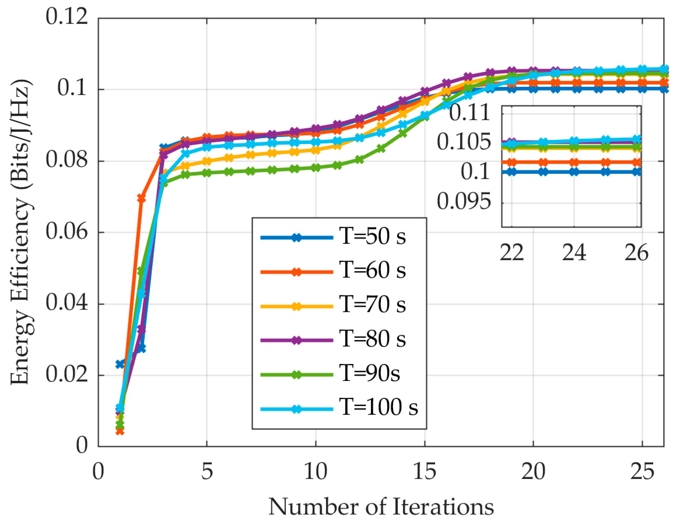
As shown in the convergence curves under different T in Figure 3, the proposed optimization algorithm demonstrates significant convergence characteristics after multiple iterations within 60–100 s. The system energy efficiency value progressively increases from its initial state, gradually approaching the steady state, and ultimately stabilizes within the predefined convergence threshold. These results conclusively validate the effectiveness of the algorithm. Through precise dynamic beamforming control and UAV trajectory optimization, it not only achieves sustained improvement in energy efficiency but also ensures reliable convergence to a stable operating point, delivering robust steady state performance in an urban high-blockage environment.
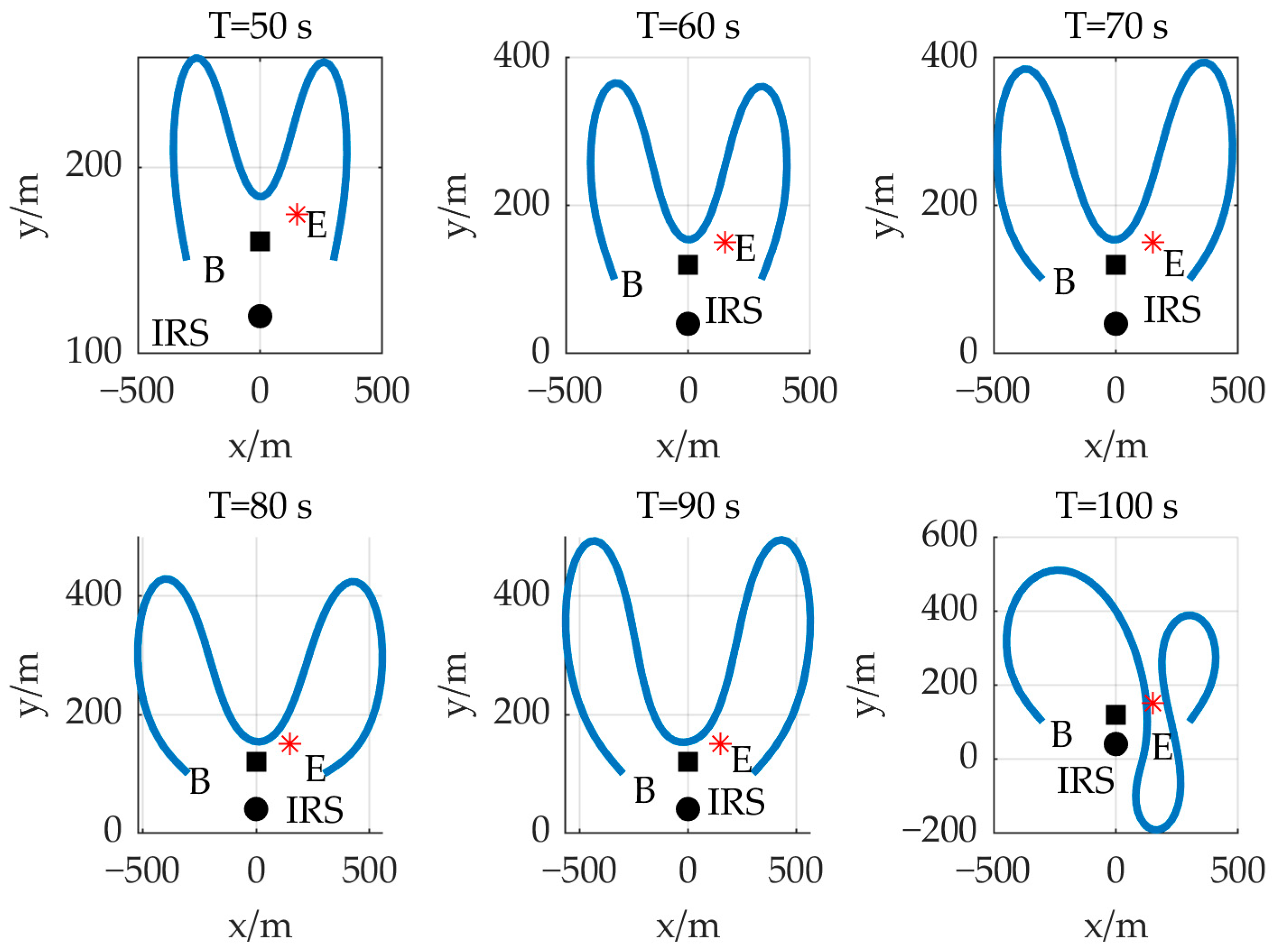
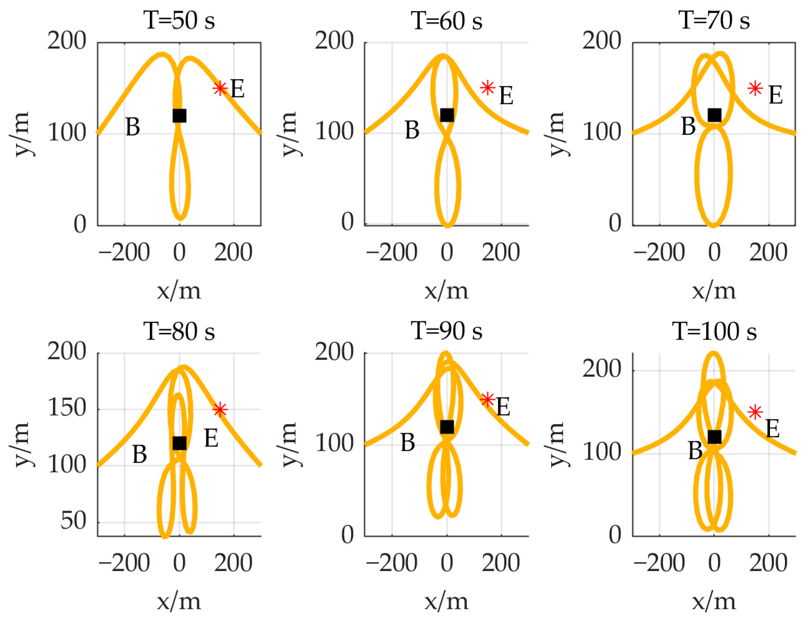
The trajectories of the UAV under different schemes within 60–100 s are compared in Figure 4, Figure 5 and Figure 6. Combined with theoretical analysis, these results indicate that UAV energy consumption is closely related to its speed magnitude and changes in velocity. Consequently, the optimal trajectory tends to approximate a straight line or maintain a large turning radius to reduce energy consumption.
The comparison between Figure 4 and Figure 5 reveals the critical role of IRS deployment. In the Figure 3, Figure 4 and Figure 5, the IRS, Base station B and eavesdropper E are represented by circles, squares, and *, respectively. In the absence of IRS assistance, the system lacks passive beamforming capability, rendering it unable to effectively manipulate channel conditions. To obtain barely acceptable link quality, the UAV is forced to perform frequent, short-range reciprocating maneuvers near base station B. While this may transiently improve the instantaneous channel state, it significantly increases propulsion energy consumption and risks communication interruption.
The trajectory comparison between the optimized IRS and random phase shift schemes in Figure 6 further validates the importance of dynamic beamforming. In the random phase shift scheme, the reflection unit phases of the IRS are unoptimized and fail to actively adapt to channel variations. Consequently, its passive beamforming capability exhibits static or random characteristics. To compensate for this deficiency, the UAV trajectory displays a distinct “inward-bending” tendency, flying closer to the axis between base station B and IRS. The trajectory reflects the UAV’s need to actively shorten the physical distance to the signal source and IRS, thereby boosting the received signal strength to offset the lack of beamforming gain. However, this proximity necessitates more tortuous paths and sharper directional adjustments, further degrading energy efficiency.
In summary, the simulated trajectory highlights the impact of IRS dynamic beamforming on UAV energy efficiency. By intelligently reconfiguring the wireless channel, it enables the UAV to adopt flight path closer to the energy-optimal configuration, ensuring communication quality while reducing UAV maneuvering energy consumption. Conversely, in scenarios without an IRS or with a random phase shift IRS, the UAV sacrifices trajectory optimality (requiring frequent maneuvers or proximity flying) to passively adapt to channel limitations, ultimately constraining the overall system energy efficiency.
As illustrated in Figure 7, depicting system energy efficiency under a varying number of reflecting elements, a horizontal perspective reveals that system energy efficiency increases with the number of IRS reflecting elements. This indicates that the large-scale deployment of IRS elements can significantly enhance the system passive beamforming capability. By fine-grained optimization of the IRS phase shift, the signal focusing ability is improved, thereby boosting system energy efficiency. From a vertical perspective, under the same configuration of reflecting elements, increasing the number of UAV antennas leads to a notable improvement in system energy efficiency. This demonstrates that deploying a large number of UAV antennas can substantially strengthen the UAV active beamforming capability, consequently enhancing system energy efficiency. Considering both the horizontal and vertical dimensions comprehensively, the collaborative deployment of a large-scale IRS reflecting element array and a UAV antenna array provides additional gains for both active and passive beamforming. Through joint optimization, higher system energy efficiency can be achieved.
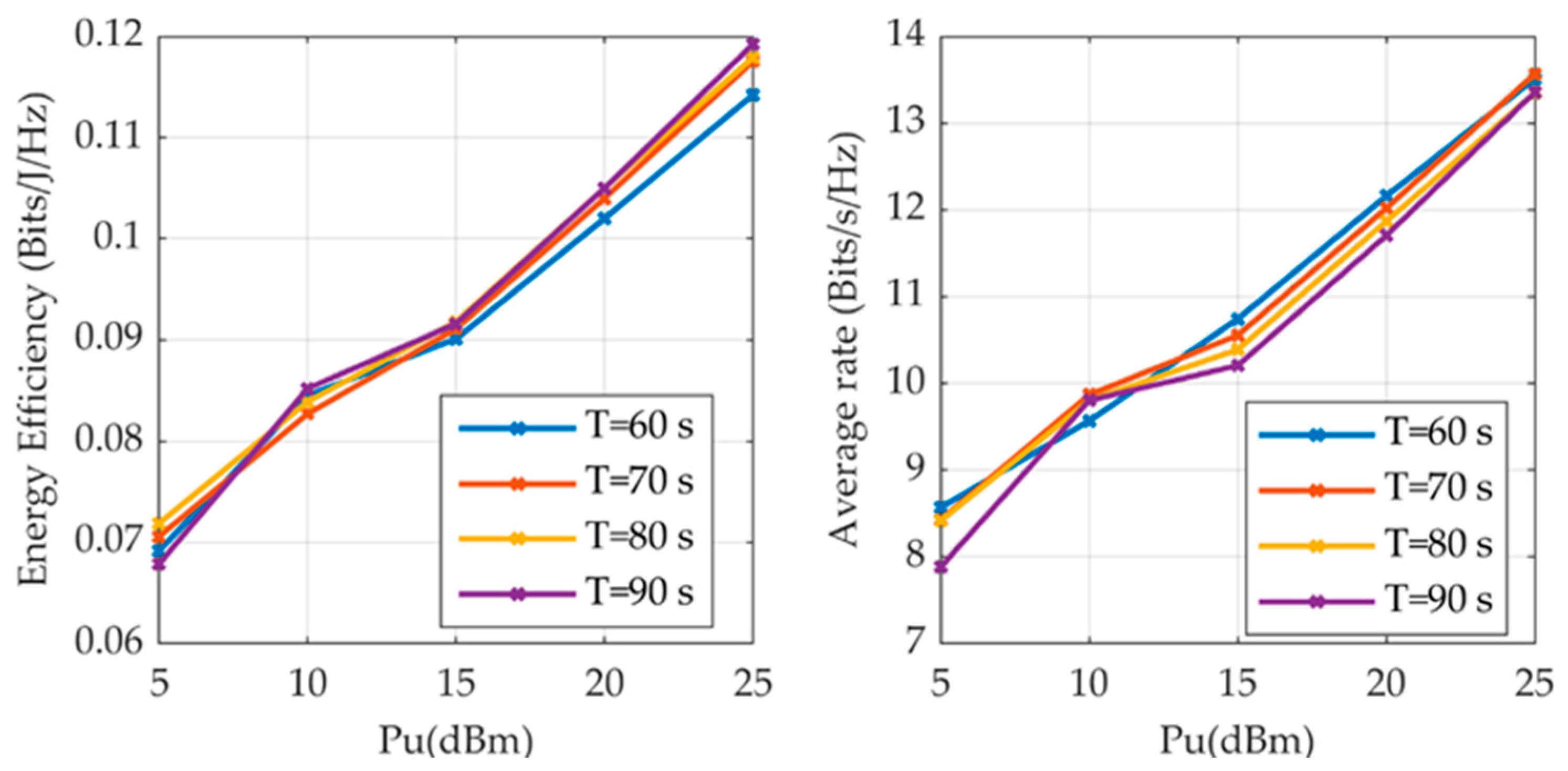
As presented in Figure 8, which shows system performance under different T and active beamforming gain values, within a communication period of T = 60–100 s, both system energy efficiency and average rate increase with the maximum active beamforming gain. This highlights the critical role of active beamforming capability in system optimization. This parameter fundamentally characterizes the maximum beam focusing gain achievable by the UAV. A higher gain value indicates stronger spatial concentration of the transmitted energy towards the IRS reception direction. Thereby, it effectively mitigates path loss and channel fading, enhancing the received signal-to-noise ratio (SNR).
As presented in Table 2 showing system performance with different IRS positions under T = 90 s (with the IRS x-coordinate fixed at 0 m), the system performance exhibits a marked nonlinear characteristic as the IRS y-coordinate varies. When the IRS moves towards the base station B from 50 m, both system energy efficiency and average rate increase, reaching their peak values at 90 m. This is attributed to the reduced path loss and enhanced ability to identify optimal reflection channel resulting from the relatively shorter distance between IRS and B as IRS approaches. This proximity strengthens the IRS beamforming capability for precise steering of signal towards the legitimate channel.
However, as the IRS position continues moving closer to and eventually beyond B, the system performance gradually degrades. Although the IRS–B distance remains small in this region, the IRS simultaneously approaches the eavesdropper. This proximity enhances the SNR of the eavesdropping link, leading to performance degradation. At the IRS y-coordinate of 150 m, which represents the closest proximity to the eavesdropper, the system performance reaches its lowest value.
Therefore, in practical engineering applications, careful consideration of the relative positions among the IRS, the B, and the eavesdropper is required to achieve optimal system performance.
As shown in Table 3 depicting system energy efficiency under different schemes and time intervals, deploying the IRS with dynamic phase optimization yields a significant improvement in system energy efficiency. Compared with the scheme without an IRS, the IRS-optimized scheme achieves an average enhancement of 0.0867 Bits/J/Hz in energy efficiency across all time points. This demonstrates the substantial impact of IRS hardware deployment in enhancing signal coverage, mitigating wireless channel fading, and enabling effective beamforming. Without IRS deployment, the system exhibits significant performance degradation.
In contrast to the random phase scheme, even with the IRS deployed, fixing its phase shifts to random values results in an average reduction of 0.0545 Bits/J/Hz in energy efficiency compared to the optimized IRS scheme during the 60–100 s interval. This indicates that merely deploying the IRS with random phase settings fails to effectively utilize channel state information (CSI) for signal focusing. Consequently, dynamically optimizing the IRS’s passive beamforming (i.e., optimizing the IRS phase shift matrix) is crucial for steering the signals, thereby maximizing system energy efficiency.
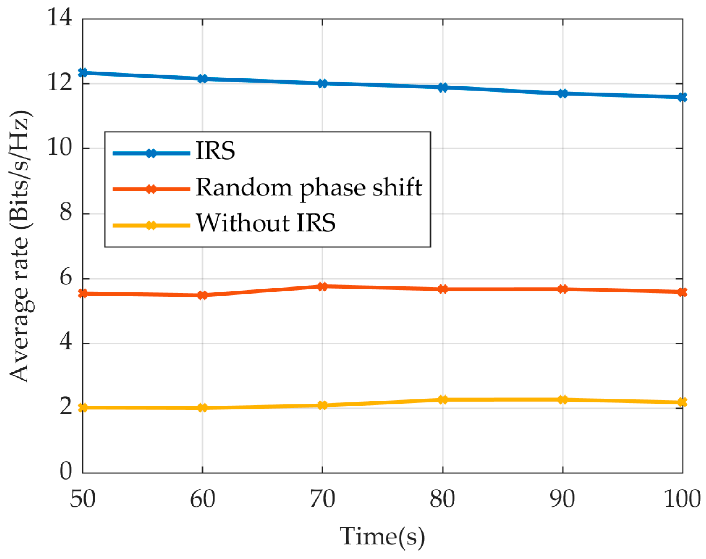
As illustrated in Figure 9, showing the system average rate with different schemes under different values of T, and combined with Table 3, the substantial improvement in system energy efficiency is primarily driven by the IRS scheme significant enhancement of the average rate. The figure visually demonstrates that, compared with both the scheme without an IRS and the random phase shift scheme, the dynamically optimized IRS passive beamforming scheme achieves a markedly higher system rate. A higher rate signifies the ability to transmit more data within the same time duration or energy consumption, which is the direct cause of the substantial energy efficiency gain. The IRS enhances the rate by optimizing its phase shift to reconfigure the wireless environment, thereby steering signal more precisely and efficiently towards the base station B. These achieved higher rates are ultimately translated into improved energy efficiency.

5. Conclusions

This paper studies the secure energy efficiency maximization problem for the IRS-assisted UAV communication in the presence of an eavesdropper. The original problem is decomposed into three sub-problems: (1) UAV active beamforming can obtain closed-form solution directly; (2) for the optimization of the IRS phase shift matrix, we propose an optimization algorithm based on Riemannian manifolds to reduce computational complexity; (3) the UAV trajectory optimization problem is non-convex and fractional, while the SCA method and Dinkelbach algorithm can be used to solve it to obtain its optimal solution. Simulation results validate that the proposed scheme significantly enhances secure energy efficiency against benchmark schemes under various scenarios. Compared with the scheme without an IRS and the random phase shift scheme, the energy efficiency value has increased by an average of 0.0864 Bits/J/Hz and 0.0543 Bits/J/Hz in the communication time of 50–100 s, respectively. Future work will extend to the multiple base station scenario. Moreover, we will also explore more complex and practical configurations, such as multi-UAV cooperative networks, dynamic IRS deployment and mobility optimization, as well as robust transmission design under an imperfect channel information state.

Author Contributions

Conceptualization, J.L. and J.C.; methodology, J.L.; software, J.L.; validation, J.L., J.C. and P.L.; formal analysis, J.L. and P.L.; investigation, J.L.; resources, J.C.; data curation, J.L.; writing—original draft preparation, J.L.; writing—review and editing, J.L.; visualization, P.L.; supervision, J.C.; project administration, J.C.; funding acquisition, J.C. All authors have read and agreed to the published version of the manuscript.

Funding

This study is sponsored by the National Key Research and Development Program of China (No. 2021YFB3901300), the National Natural Science Foundation of China (Grant 42204035), the Heilongjiang Province Youth Science and Technology Talent Support Program (No. 2024QNTJ019), and the Heilongjiang Provincial Key R&D Program (Innovation Base) (No. JD2023SJ09).

Data Availability Statement

The original contributions of this work are fully contained within this article. For further information, inquiries may be addressed to the corresponding author.

Conflicts of Interest

The authors declare no conflicts of interest.

References

  1. Saad, W.; Bennis, M.; Chen, M. A Vision of 6G Wireless Systems: Applications, Trends, Technologies, and Open Research Problems. IEEE Netw. 2020, 34, 134–142. [Google Scholar] [CrossRef]
  2. Ahokangas, P.; Matinmikko-Blue, M.; Yrjölä, S. Envisioning a Future-Proof Global 6G from Business, Regulation, and Technology Perspectives. IEEE Commun. Mag. 2023, 61, 72–78. [Google Scholar] [CrossRef]
  3. Mozaffari, M.; Saad, W.; Bennis, M.; Nam, Y.H.; Debbah, M. A Tutorial on UAVs for Wireless Networks: Applications, Challenges, and Open Problems. IEEE Commun. Surv. Tutor. 2019, 21, 2334–2360. [Google Scholar] [CrossRef]
  4. Chen, X.; Sheng, M.; Li, B.; Zhao, N. Survey on Unmanned Aerial Vehicle Communications for 6G. J. Electron. Inf. Technol. 2022, 44, 781–789. [Google Scholar]
  5. Tang, X.; Chen, F.; Wang, F.; Jia, Z. Disaster-Resilient Emergency Communication with Intelligent Air–Ground Cooperation. IEEE Internet Things J. 2024, 11, 5331–5346. [Google Scholar] [CrossRef]
  6. Dicandia, F.A.; Fonseca, N.J.G.; Bacco, M.; Mugnaini, S.; Genovesi, S. Space-Air-Ground Integrated 6G Wireless Communication Networks: A Review of Antenna Technologies and Application Scenarios. Sensors 2022, 22, 3136. [Google Scholar] [CrossRef]
  7. Zhang, P.; Chen, S.; Zheng, X.; Li, P.; Wang, G.; Wang, R.; Wang, J.; Tan, L. UAV Communication in Space–Air–Ground Integrated Networks (SAGINs): Technologies, Applications, and Challenges. Drones 2025, 9, 108. [Google Scholar] [CrossRef]
  8. Wu, M.; Xiao, Y.; Gao, Y.; Xiao, M. Digital Twin for UAV-RIS Assisted Vehicular Communication Systems. IEEE Trans. Wirel. Commun. 2024, 23, 7638–7651. [Google Scholar] [CrossRef]
  9. Murroni, I.; Anedda, M.; Fadda, M.; Ruiu, P.; Popescu, V.; Zaharia, C.; Giusto, D. 6G—Enabling the New Smart City: A Survey. Sensors 2023, 23, 7528. [Google Scholar] [CrossRef]
  10. Yan, C.; Fu, L.; Zhang, J.; Wang, J. A Comprehensive Survey on UAV Communication Channel Modeling. IEEE Access 2019, 7, 107769–107792. [Google Scholar] [CrossRef]
  11. Hamid, H.; Begh, G.R. IRS assisted UAV communications for 6G networks: A systematic literature review. Wirel. Netw. 2025, 31, 779–807. [Google Scholar] [CrossRef]
  12. Jiao, S.; Fang, F.; Zhou, X.; Zhang, H. Joint Beamforming and Phase Shift Design in Downlink UAV Networks with IRS-Assisted NOMA. J. Commun. Inf. Netw. 2020, 5, 138–149. [Google Scholar] [CrossRef]
  13. Hua, M.; Yang, L.; Wu, Q.; Pan, C.; Li, C.; Swindlehurst, A.L. UAV-Assisted Intelligent Reflecting Surface Symbiotic Radio System. IEEE Trans. Wirel. Commun. 2021, 20, 5769–5785. [Google Scholar] [CrossRef]
  14. Li, S.; Yuan, X.; Liang, Y.C.; Renzo, D.M. Reconfigurable Intelligent Surface Assisted UAV Communication: Joint Trajectory Design and Passive Beamforming. IEEE Wirel. Commun. Lett. 2023, 17, 3670–3681. [Google Scholar] [CrossRef]
  15. Ji, Z.; Yang, W.; Guan, X.; Zhao, X.; Li, G.; Wu, Q. Trajectory and Transmit Power Optimization for IRS-Assisted UAV Communication Under Malicious Jamming. IEEE Trans. Veh. Technol. 2022, 71, 11262–11266. [Google Scholar] [CrossRef]
  16. Pang, X.; Zhao, N.; Tang, J.; Wu, C.; Niyato, D.; Wong, K.K. IRS-Assisted Secure UAV Transmission via Joint Trajectory and Beamforming Design. IEEE Trans. Commun. 2022, 70, 1140–1152. [Google Scholar] [CrossRef]
  17. Xu, B.; Hu, L.; Wei, S.; Qian, Y.; Yan, S.; Shu, F.; Li, J. On IRS-Assisted Covert Communication with a Friendly UAV. Drones 2023, 7, 453. [Google Scholar] [CrossRef]
  18. Fang, S.; Chen, G.; Li, Y. Joint Optimization for Secure Intelligent Reflecting Surface Assisted UAV Networks. IEEE Wirel. Commun. Lett. 2021, 10, 276–280. [Google Scholar] [CrossRef]
  19. Alsarayreh, A.S.; Radzi, M.A.N.; Alkahtani, A.A.; Azmi, M.H.K. Intelligent Reflecting Surface–UAV Systems in the Internet of Things Network: A Survey. IEEE Acess 2023, 11, 85031–85049. [Google Scholar] [CrossRef]
  20. Su, Y.; Pang, X.; Chen, S.; Jiang, X.; Zhao, N.; Yu, F.R. Spectrum and Energy Efficiency Optimization in IRS-Assisted UAV Networks. IEEE Trans. Commun. 2022, 70, 6489–6502. [Google Scholar] [CrossRef]
  21. Zhao, H.; Hao, J.; Guo, Y. Joint Trajectory and Beamforming Design for IRS-assisted Anti-jamming UAV Communication. In Proceedings of the 2022 IEEE Wireless Communications and Networking Conference 2022, Austin, TX, USA, 10–13 April 2022. [Google Scholar]
  22. Wu, Q.; Zhang, R. Towards Smart and Reconfigurable Environment: Intelligent Reflecting Surface Aided Wireless Network. IEEE Commun. Mag. 2020, 18, 106–112. [Google Scholar] [CrossRef]
  23. Wu, Q.; Zhang, R. Intelligent Reflecting Surface Enhanced Wireless Network via Joint Active and Passive Beamforming. IEEE Trans. Wirel. Commun. 2019, 18, 5394–5409. [Google Scholar] [CrossRef]
  24. Zeng, Y.; Zhang, R. Energy-Efficient UAV Communication with Trajectory Optimization. IEEE Trans. Wirel. Commun. 2017, 16, 3747–3760. [Google Scholar] [CrossRef]
  25. Gopala, K.P.; Lai, L.; Gamal, E.H. On the Secrecy Capacity of Fading Channels. IEEE Trans. Inf. Theory 2008, 54, 4687–4689. [Google Scholar] [CrossRef]
  26. Li, Q.; Ma, W.K. Optimal and Robust Transmit Designs for MISO Channel Secrecy by Semidefinite Programming. IEEE Trans. Signal Process. 2011, 59, 3799–3812. [Google Scholar] [CrossRef]
  27. Yuan, G.; Wei, Z.; Li, G. A Modified Polak–Ribière–Polyak Conjugate Gradient Algorithm for Nonsmooth Convex Programs. J. Comput. Appl. Math. 2014, 255, 86–96. [Google Scholar] [CrossRef]
  28. Huang, W.; Absil, A.P.; Gallivan, A.K. A Riemannian BFGS Method Without Differentiated Retraction for Nonconvex Optimization Problems. SIAM J. Optim. 2018, 28, 470–495. [Google Scholar] [CrossRef]
  29. Chen, H.J.; Schaible, S.; Sheu, R.L. Generic Algorithm for Generalized Fractional Programming. J. Optim. Theory Appl. 2008, 141, 93–105. [Google Scholar] [CrossRef]
  30. Yu, Y.; Liu, X.; Liu, Z.; Durrani, T.S. Joint Trajectory and Resource Optimization for RIS Assisted UAV Cognitive Radio. IEEE Trans. Veh. Technol. 2023, 72, 13643–13648. [Google Scholar] [CrossRef]
Figure 1. UAV–IRS–base station/eavesdropper system.
Drones 09 00648 g001
Figure 2. IRS-assisted UAV communication system.
Drones 09 00648 g002
Figure 3. Convergence performance of the algorithm under different values of T.
Drones 09 00648 g003
Figure 4. UAV trajectory with an IRS under different values of T.
Drones 09 00648 g004
Figure 5. UAV trajectory without an IRS under different values of T.
Drones 09 00648 g005
Figure 6. Comparison of IRS and random phase shift UAV trajectory under different values of T.
Drones 09 00648 g006
Figure 7. System energy efficiency with different numbers of reflection units under T = 90 s.
Drones 09 00648 g007
Figure 8. System performance with different active beamforming value under different values of T.
Drones 09 00648 g008
Figure 9. Comparison of system average rate with different schemes under different values of T.
Drones 09 00648 g009
Table 1. Simulation parameters.
Simulation ParameterPhysical MeaningValue
UAV altitude H u 100 m
IRS altitude H R 30 m
Number of UAV antennas N u 8
IRS reflection unit number M x , M y 8
UAV maximum velocity V max 50 m/s
UAV maximum acceleration a max 5 m/s2
Channel power gain ρ −30 dB
Noise power σ B 2 ,   σ E 2 −60 dBm
Path loss exponent α 2.2
Rician factorK5
UAV maximum power P u max 20 dBm
Threshold ε 10 3
Table 2. Comparison of system performance at different IRS positions under T = 90 s.
IRS y-Coordinate
(m)
Energy Efficiency
(Bits/J/Hz)
Average Rate
(Bits/s/Hz)
500.106711.8643
700.112812.9223
900.115213.2201
1100.114413.1315
1300.114213.1116
1500.104511.8864
Table 3. Comparison of system energy efficiency with different schemes under different values of T (Bits/J/Hz).
Time(s)IRSWithout IRSRandom Phase Shift
500.09210.01310.0449
600.1020.01320.0444
700.1040.01360.0450
800.1050.01280.0423
900.1050.01320.0486
1000.09090.01360.0470
Disclaimer/Publisher’s Note: The statements, opinions and data contained in all publications are solely those of the individual author(s) and contributor(s) and not of MDPI and/or the editor(s). MDPI and/or the editor(s) disclaim responsibility for any injury to people or property resulting from any ideas, methods, instructions or products referred to in the content.