1. Introduction
Advances in scientific and technological fields, such as information technologies, aeronautical technology, and the development of more compact, lightweight, and economical batteries, have allowed the unmanned aerial vehicle (UAV) market to grow in recent years [
1]. Production is projected to increase from 2 million UAV units in 2021 to 6.5 million units by 2030, representing a compound annual growth rate of 14.1% [
2]. This has generated a growing use of UAVs in the industry, and new applications can be carried out using these devices, allowing the reduction of time and economic costs to the operator.
Systems composed of multiple UAVs, called UAV swarms, offer many advantages, such as decreased operating time, reduced mission failure rates, and multitasking capacity [
3]. UAV swarms need long-range communication technologies that allow them to cover large land areas. Usually, these network exchanges control messages and telemetry, which do not require large bandwidth. Thus, technologies operating at the sub-1 GHz band [
4] fit these features very well. However, many applications also require real-time video transmissions from a UAV to the ground control station (GCS), giving rise to the need for greater link capacities found in higher frequency bands. To face the trade-off between bandwidth and range, we propose the use of multi-hop networks to enable video transmission from remote positions to the GCS.
The main purpose of this paper is to explore the benefits of combining two radio interfaces onboard an unmanned aerial vehicle (UAV) to communicate with a GCS and other UAVs inside a swarm. The goals are to use the IEEE 802.11ah specification [
5] (certified as Wi-Fi HaLow), which provides long-range communication (beyond 1 km) but offers a limited application throughput, combined with IEEE 802.11ax standard [
6] (certified as Wi-Fi 6/6E), which is the latest mainstream Wi-Fi release available in consumer electronic devices and offers high throughput at short/medium distances. Note, however, that modern Wi-Fi 6 devices dynamically adjust their PHY configuration based on channel conditions and may fall back to legacy modes when necessary. The choice of technologies is based on a criterion according to which these two technologies complement each other, enabling greater communication ranges without sacrificing data rate. The proposed communications system is analyzed in the particular context of a UAV swarm executing a mission in which the objective is to inspect an airport runway. When a UAV detects structural damage, the location is designated as a point of interest (POI), prompting the swarm to establish the necessary conditions for real-time video transmission to the ground control station (GCS). During video transmission, UAVs participating in the data path remain stationary, so there is no mobility during the real-time video transmission. While airport runway inspection serves as the proof-of-concept use case, the proposed multi-hop architectures apply to other medium-range UAV operations (i.e., a few kilometers) requiring real-time video transmission, such as natural disaster relief and agricultural monitoring.
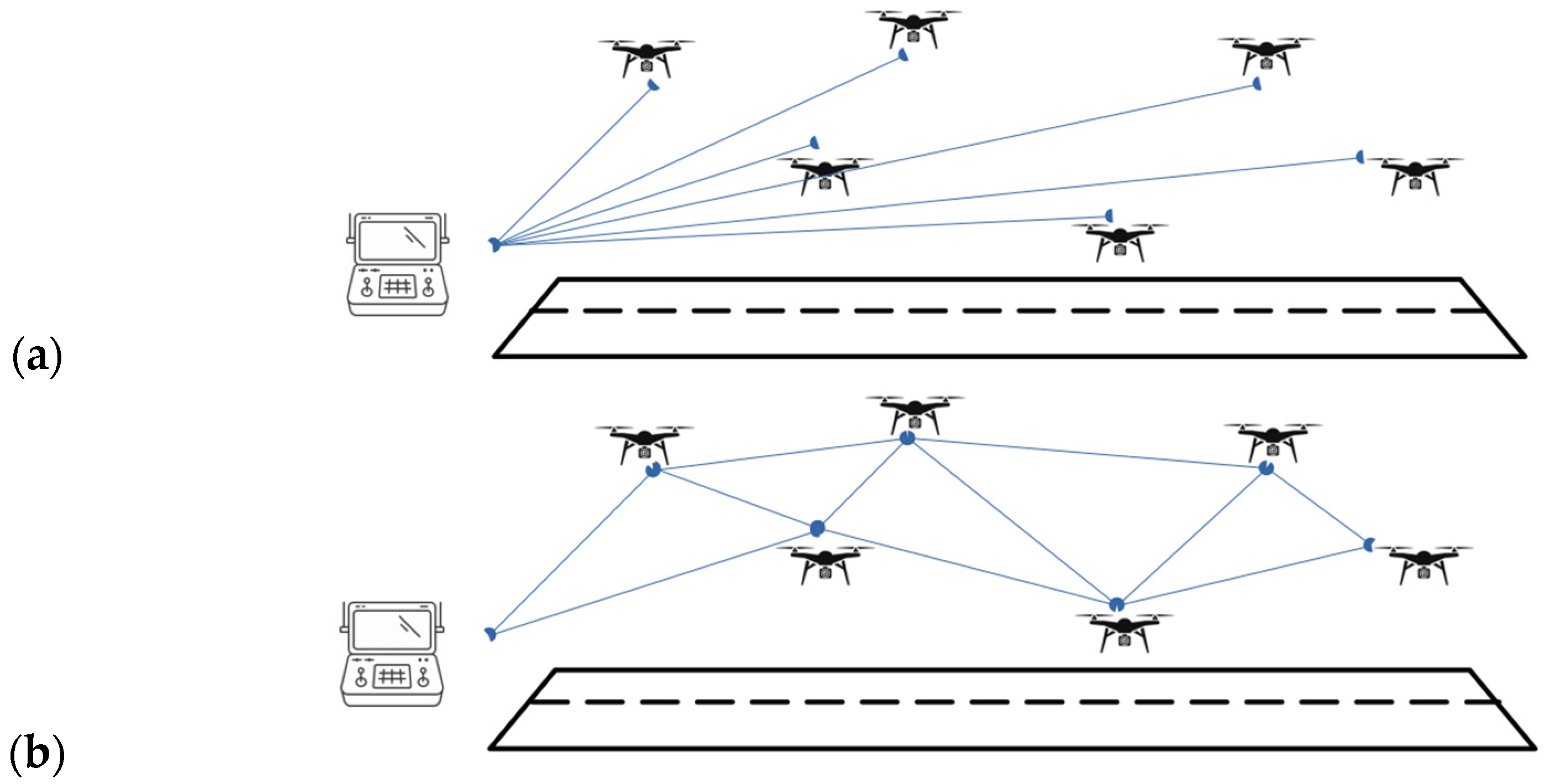
The coordination necessary for establishing a multi-hop network for video transmission is facilitated through the implementation of communication networks. Centralized and decentralized architectures are evaluated to determine which approach is more suitable for the proposed application. In centralized communication networks, a single central node oversees the routing and data flow, which can enhance management efficiency and control. In contrast, decentralized communication networks distribute these responsibilities across multiple nodes, fostering greater resilience and scalability in dynamic environments. Both network architectures are represented in
Figure 1.
The main contributions of this paper can be summarized as follows:
The proposal of a dual-radio communication architecture that combines a long-range, low-data-rate interface with a short/medium-range, high-data-rate interface, effectively addresses the trade-off between communication range and throughput.
The development of a model for the capacity of a multi-hop network, which enables the estimation of the overall network capacity based on the individual capacities of its links. The proposed model is partially based on real-world measurements and has been validated through simulations conducted in NS-3.
The implementation and evaluation of novel heuristic-based strategies for establishing multi-hop networks for video transmission through drone swarms. These strategies are assessed using key performance metrics such as throughput, network setup delay, and UAV energy consumption.
The analysis and comparison of the performance of centralized and decentralized control communication architectures for the establishment of multi-hop networks. Their impact has been evaluated using the aforementioned metrics: throughput, network setup delay, and UAV energy consumption.
To realize the proposed solution, each UAV in the swarm will be equipped with a companion computer capable of executing lightweight Python-based scripts (v3.10.12). These computers (e.g., a Raspberry Pi) communicate with the UAV’s autopilot using the MavLink protocol. In this study, the autopilot is emulated utilizing the Dronekit-SITL environment in scenarios with up to 12 UAVs per swarm.
First, a review of the state of the art of the research on UAV swarm communications is presented in
Section 2. Next,
Section 3 provides an analysis of the different Wi-Fi technologies integrated into our approach.
Section 4 is devoted to the process of finding an expression to obtain the video transmission capacity in a multi-hop network, which is verified against NS-3 simulations.
Section 5 describes our scenarios of interest and how they were emulated in a virtual environment. In
Section 6, the results are analyzed and discussed. The focus is on delay-related measurements, video transmission mesh capacity, communications path length, and energy consumption.
2. Related Work
As mentioned in
Section 1, UAV swarms are becoming a research topic that is attracting the attention of many researchers. As a result, a large number of surveys have been developed focusing on different aspects of this subject [
3]. Also, many applications are proposed, in which the use of UAV swarms leads to a very relevant improvement in terms of time, range, or performance compared to currently used methods. The implementation of this new paradigm requires developing new algorithms to solve complex problems.
In Ref. [
3], an extensive survey of the research published related to UAV swarms is carried out. In it, a taxonomy is proposed according to the aspects that those works deal with. The covered aspects are AI/ML-enabled UAV swarm, game theory-controlled UAV swarm, swarm formation control, communications and routing, path planning, task assignment, decision making and autonomous behavior, coordination and cooperation, security and privacy, and energy management. From them, those concerning the research carried out in this paper are as follows:
Swarm formation control. A distinction is made between the leader–follower approach and behavior-based or virtual structure-based approaches. In our case, a static leader–follower approach is implemented where GCS is the leader.
Communications and routing. Communications present many challenges, such as mobility, reliability, battery lifetime, scalability, etc. Nodes can be connected following different topologies, such as ring, star, mesh, fully connected, etc. In our scenarios, we use centralized and decentralized terms to distinguish the communication architectures used. Star topology is used for the centralized approach and mesh for the decentralized one (
Figure 1). Regarding routing, protocols can be intelligence based or use conventional routing. In the proposed scenarios, a static routing and a reactive ad hoc protocol, similar to Ad hoc On-Demand Vector (AODV) [
7] routing, are implemented for centralized and decentralized approaches, respectively.
Task assignment. Many of the algorithms developed for this issue present an auction-based model. In our case, we assign the task of participating in the communications path, considering the distance that the UAVs have to travel as a key coefficient.
Decision making and autonomous behavior. Authors distinguish between global and distributed decision making. In our proposed scenarios, the decisions are taken globally from the active node on the swarm.
Coordination and cooperation. Coordination is explained as the synchronization or accommodation of different aspects of the mission (e.g., the trajectories) to guarantee that it can be executed correctly. To do so, it is fundamental to share information, resources, spatial coordinates, temporal coordinates, etc. Cooperation is the act through which the swarm UAVs exhibit collaborative behavior to accomplish the mission objectives. Combining sensing, planning, and control information with a decision architecture makes this collaborative behavior possible.
Very few of the published studies offer solutions to build a multi-hop wireless mesh for inter-UAV and UAV-GCS communications, which meet the requirements of long-distance transmission for bandwidth-demanding applications.
In Ref. [
4], a scenario is shown where the IEEE 802.11ah physical layer (PHY) is modified to enhance throughput performance, enabling the transmission of video data within a drone swarm where UAVs are positioned approximately one kilometer apart. In Ref. [
8], Alam et al. propose a swarm composed of dynamic groups defined geographically, which enables video transmissions through relay UAVs. IEEE 802.11ah is combined with a Gauss–Markov Model for UAV location prediction to efficiently transfer video and reduce communication delay and coverage gaps. Despite their improvement in throughput performance, it is still limited to 400 kbps. Therefore, there are signs of the difficulty involved in transmitting video over the swarm with relay UAVs. Finally, In Ref. [
9], some practical measurements are made with a real UAV carrying a Raspberry Pi 3B with a Wi-Fi HaLow module attached. The UAV’s wireless link reached a kilometer, achieving throughputs over 1 Mbps with a received signal strength indicator (RSSI) between −70 and −80 dBm in all cases. Throughput and RSSI behavior concerning altitude seems to be better for lower altitudes when distances are short, but more stable when distances increase, since it is less susceptible to obstacles.
Although energy efficiency in multi-hop networks is a widely studied field and protocols have been developed to minimize energy consumption at both the device level and the global network level [
10], flying ad hoc networks (FANETs) are usually treated as a separate case. In FANETs, the communication hardware typically shares the UAV’s power source, and its energy consumption is negligible compared to that of the propulsion system [
11], making energy efficiency a less critical performance metric.
In this paper, we propose a novel solution that covers large distances while reaching multi-Mbps throughput with devices complying with the IEEE 802.11 standards. In contrast to [
4], our solution requires no modifications to existing standards and is fully compatible with off-the-shelf Wi-Fi HaLow devices. Moreover, the integration with a high-data-rate radio addresses the throughput limitations reported In Ref. [
8].
3. Performance Studies on Wi-Fi Technologies
To evaluate the performance and capacity of the multi-hop wireless links within our proposed architecture, we conducted a comprehensive measurement campaign. Using real-world Wi-Fi 6 and Wi-Fi HaLow devices, we collected throughput data under varying conditions and distances. This analysis provides valuable insights into the capabilities of each technology and its suitability for different network scenarios. In the next subsections, a review of each technology is provided, emphasizing the strengths and weaknesses of each one.
3.1. IEEE 802.11ah
The IEEE 802.11ah amendment was published in 2017 to satisfy the necessity of the Internet of Things (IoT) paradigm. This technology works in the license-free sub-1 GHz band (from 863 MHz to 868 MHz in the EU) with possible configurable bandwidths of 1, 2, 4, 8, and 16 MHz (1 and 2 MHz in the EU). It defines 41 different Modulation Coding Schemes (MCSs), 11 for a single multiple-input multiple-output (MIMO) spatial stream and 10 for other cases (2, 3, and 4 spatial streams). These and other features offer longer ranges than other Wi-Fi technologies, going beyond a kilometer. However, Wi-Fi HaLow provides lower bitrates, ranging from 150 kbps (MCS 10) to 347 Mbps, when configured with four spatial streams, channels with a maximum bandwidth of 16 MHz, and short guard interval [
12].
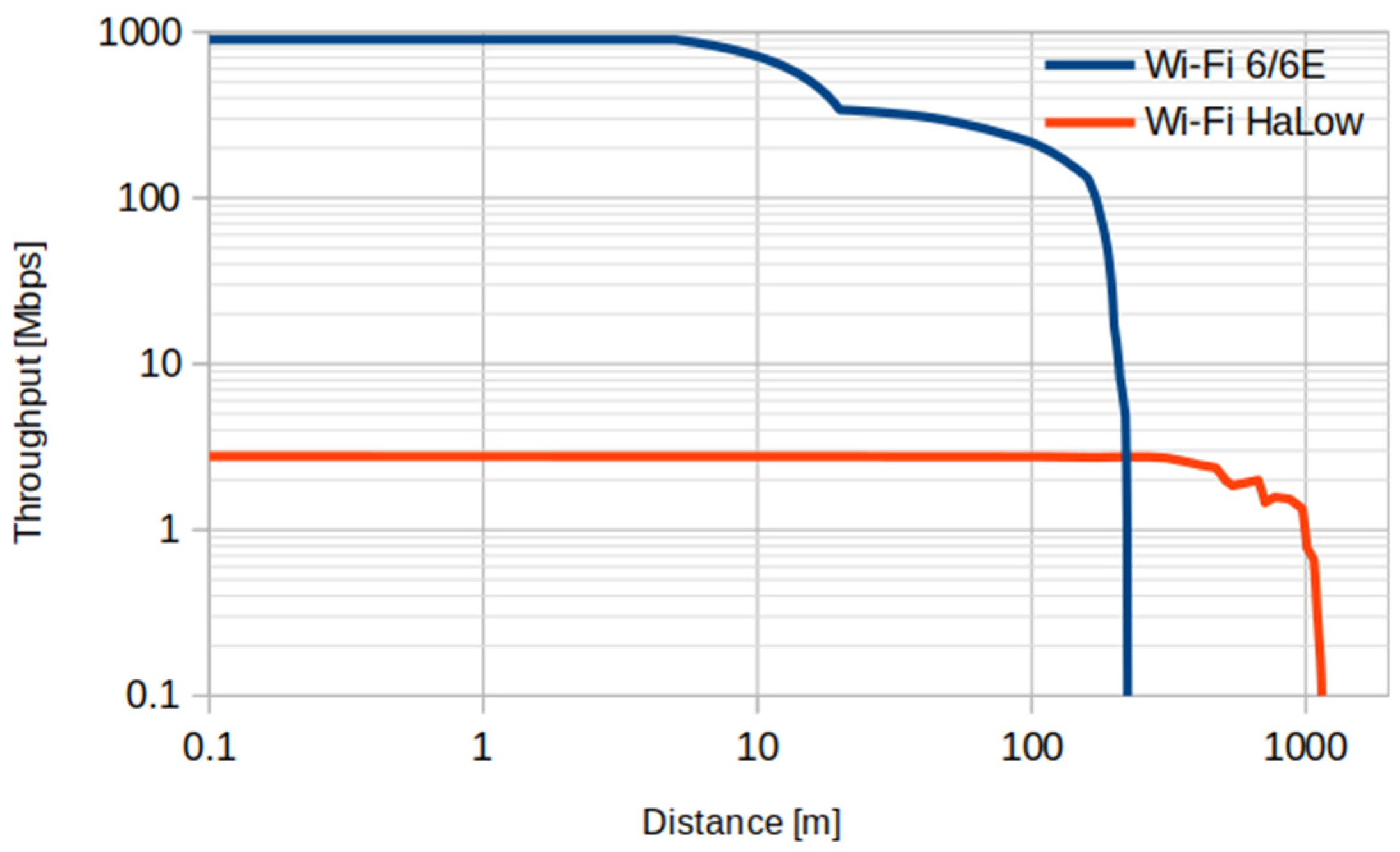
Real throughput measurements were performed with the NRC7293 chipset, complying with the IEEE 802.11ah standard. From these measurements, the throughput vs. distance performance with 1 MHz of bandwidth in an outdoor environment (
Figure 2) is used as a reference for Wi-Fi HaLow communications between the emulated drones. This Wi-Fi configuration was purposely chosen to maximize coverage range.
3.2. IEEE 802.11ax
The IEEE 802.11ax amendment was released in 2021 by the IEEE 802.11 Working Group. Wi-Fi 6/6E is the latest generation of Wi-Fi technology widely adopted today. It offers significant performance enhancements over previous generations, including faster data rates, increased capacity, and improved efficiency [
13]. This standard incorporated the 6 GHz band with the previously used 2.4 GHz and 5 GHz bands. It defines channel bandwidths of 20, 40, 80, and 160 MHz, and up to 8 MIMO spatial streams with 12 MCS for each of them, which means a total of 96 MCS, with 1024-QAM being the fastest modulation. This and other features enable a maximum PHY bitrate of 9.6 Gbps.
Regarding IEEE 802.11ah, a study identifying the throughput vs. distance performance for Wi-Fi 6/6E was carried out and used as a reference for the link capacity estimations. For this case, the AX210 chipset was employed and configured to operate in the 6 GHz band with a bandwidth of 80 MHz.
Figure 2 also shows the throughput values measured for Wi-Fi 6/6E.
The proposed dual-interface configuration is compatible with typical UAVs used on civil applications in terms of payload weight and consumption. Usually, network equipment weighs over a few hundred grams, while maximum payload weights can be in the range of a few kilograms. Regarding energy limitations, Wi-Fi interfaces typically consume between 100 and 300 mA when active, and UAV motors require about tens of amps. There are some available commercial devices that include both Wi-Fi technologies (i.e., Wi-Fi HaLow and legacy Wi-Fi). For example, LilyGo T-Halow [
14] comes with an ESP32-S3 microcontroller, which includes Bluetooth, legacy Wi-Fi and a Wi-Fi HaLow interface, and weighs 50 g. The continuous transmission consumption of the IEEE 802.11ah module present in the LilyGo device is 300 mA [
15]. The ESP32-S3, also integrated in LilyGo T-Halow, consumes up to 283 mA (depending on the configured tx power) when transmitting through the integrated Wi-Fi interface [
16].
4. Expression for Multi-Hop Network Capacity Calculation
Once the performance of single Wi-Fi links is known, a further step is needed to obtain the capacity of multi-hop links. Hence, we developed a measurement-based analytical expression to evaluate the end-to-end capacity of multi-hop Wi-Fi links. Distances between the nodes that compose the multi-hop path are received as input parameters. With this method, first, we obtain the capacity of each link individually and, next, the total capacity of the multi-hop network considering the interference and interactions caused by the different transmitters in the network.
4.1. Per-Link Capacity Calculation
Taking the results of the throughput measurements for the different Wi-Fi technologies (cf.
Section 3) and the distance between two UAVs acting as network nodes, a hypothetical throughput between both nodes forming a link can be estimated. To achieve better accuracy, the throughput values for distances between measured points are interpolated. Thus, the distance between the nodes can be mapped to a throughput.
4.2. Multi-Hop Network Characterization from Defined Hops
Once all the links of the network have been characterized, it is necessary to see how they combine and result in the multi-hop network.
When the nodes of the multi-hop network are equipped with a single radio interface, they must be configured to the same frequency channel, thus competing to access the common medium. As shown In Ref. [
17], in a network where
n nodes contend for access to the same channel with equal priority, each node achieves the same individual throughput, regardless of its PHY rate. This individual throughput can be approximated as
where
ri represents the saturation throughput a STA
i would achieve in the absence of contention (i.e., as if it were transmitting alone on the channel).
The NS-3 simulator [
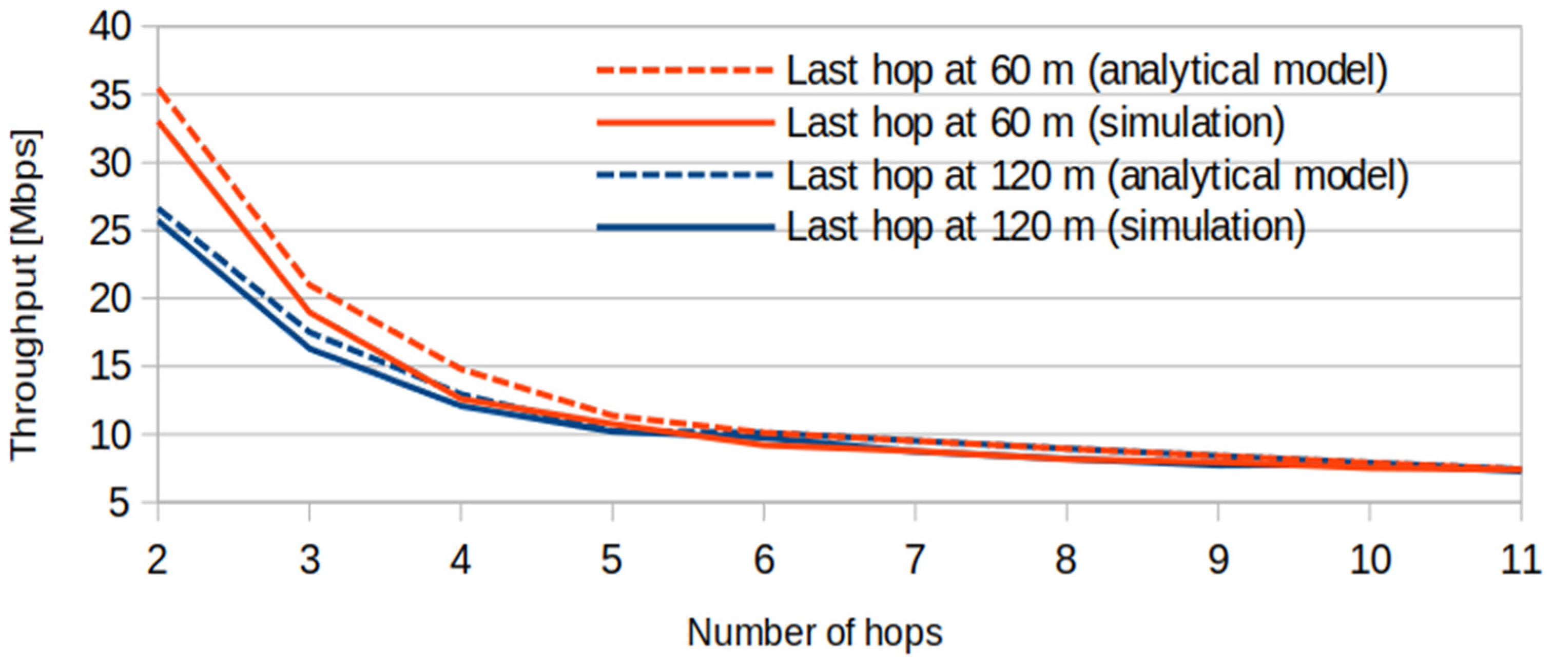
18] has been employed to simulate multi-hop networks of several lengths, from 2 to 11 hops, arranged along a straight line. The distance between nodes was 120 m except in the case of the source node and its neighbor; the distance between them varied from 0 to 120 m in 10 m intervals. These simulations showed a clear tendency that agrees with Equation (1) until the network is composed of six nodes (i.e., five hops). However, for six or more hops, the capacity decreases at a slower rate. This is because communications are affected by the interference generated by the five closest links. Beyond the fifth hop, the interference shows almost negligible impact due to the large distance. Therefore, the network capacity will be limited by the set of six consecutive nodes whose links give rise to the network segment with the lowest capacity. Beyond five hops, the throughput drop is due to an increase in transmission errors due to the interference from outside the communication range. This behavior is consistent with observations by prior studies, including testbed measurements (e.g., see [
19]). Equation (2) is the resulting expression from adding these particularities.
S is the total capacity of the multi-hop network,
pe is a transmission error probability added for each additional hop once the five hops have been exceeded,
n is the number of transmitting nodes (i.e., the total number of links in the multi-hop network),
j is the position of the first link composing the bottleneck and
ri is the capacity of link
i.
After trying different values for p
e, the one that minimized the error relative to the results provided by NS-3 was 0.06.
Figure 3 presents the results from applying the obtained analytical expressions, comparing them with those obtained from simulations for the cases of 60 m and 120 m in the last hop. The behavior in both cases is quite similar, and, thus, the expressions found can be given as a good approximation for assessing the throughput performance of an IEEE 802.11 multi-hop network and serve as the basis for the path selection/formation mechanisms explained in the following sections. Note, however, that the values of
and the interference range of
n = 5 hops are specific to the propagation loss model used. These parameters must be reevaluated for different scenarios.
Parameters and n depend on factors such as the receivers’ sensitivity and the propagation characteristics of the environment. To adjust parameter n, the degree of the nodes in the multi-hop network is established (i.e., how many nodes are within communication range). To adjust , it is necessary to determine how the transmissions of the nodes outside the communication range, but within the interference area, are affected by the transmissions of a certain node. This can be achieved through experimental measurements or simulations that replicate the expected conditions. In our simulations, receiver sensitivity is set to the minimum value specified by the IEEE 802.11 standard, which is considered a conservative estimate compared to current commercial devices. It is also worth noting that the model does not require that the nodes participating in the multi-hop path are aligned in a straight line, as long as the number of nodes within communication range does not exceed n.
In consequence, we argue that both Equations (1) and (2) are valid for other environments if parameters and n are adjusted.
5. Emulated Scenarios
In this section, we introduce all the proposed scenarios after a description of the emulation environment.
5.1. Emulation Environment
Figure 4 shows the architecture of the environment used for the emulations. The GCS is emulated with a Python script, which we called GCS.py, and serves as the primary program responsible for coordinating the swarm throughout the mission. The environment deployment consists of the execution of the commands to launch the Dronekit-SITL and MAVProxy instances. Dronekit-SITL is a UAV system emulator [
20], which offers an interface to communicate with an emulated autopilot via Micro Air Vehicle Link (MAVLink) protocol [
21]. It also emulates the dynamics of the UAV as a function of the commands received from the GCS or the progress of the flight plan. MAVProxy [
22] is a minimalist GCS that allows the deployment of a proxy that receives MAVLink traffic from one device and forwards it to several destinations. In our environment, it is used to forward the UAV telemetry to both the GCS.py script and QGroundControl [
23], which is a GCS with a graphical user interface (GUI) used to supervise the mission.
To handle the swarm management, GCS.py uses instances of the Vehicle object defined in vehicle.py. This object emulates the software that would be running in the UAVs’ companion computer. The script vehicle.py uses the Dronekit-python library to communicate with the emulated autopilot (i.e., the Dronekit-SITL instance) through the MAVProxy instance. Dronekit-python is a Python module used to communicate with MAVLink-speaking devices from a Python program.
The metrics resulting from the emulations are recorded into a file for subsequent analysis.
5.2. Definition of the Scenarios
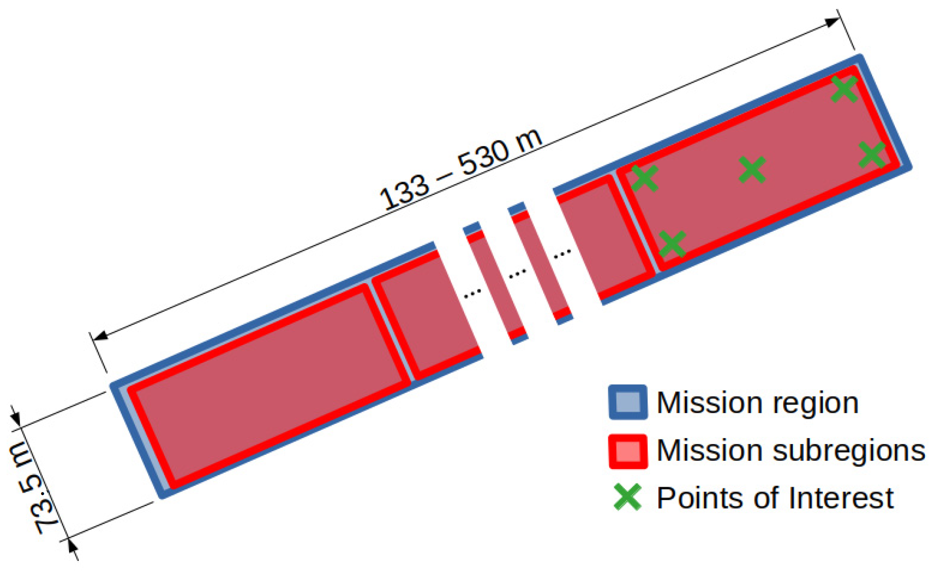
All the emulated scenarios have been designed within the context of a use case in which a swarm of UAVs inspects a rectangular region (e.g., airport runway) searching POIs. Both the boundaries of the region to survey and the POIs are defined before starting the emulation. Depending on the length of the region to scan, a certain number of UAVs are initialized, and each one is assigned a portion of the region. All drones execute their missions in auto mode (i.e., man-on-the-loop) independently of each other until a POI is discovered. When any of the UAVs finds a POI, a process begins to enable the transmission of video through the swarm from the UAV that found the POI to the GCS. Only one POI was placed for each mission. Each mission was emulated at least five times, with five different POI positions. The POI is always placed within the furthest subregion, as shown in
Figure 5. We note that the proposed architecture is compatible with IEEE 802.11 authentication and encryption mechanisms in ad hoc mode. Although it is not a requirement for Wi-Fi HaLow products, devices compatible with this encryption system are available.
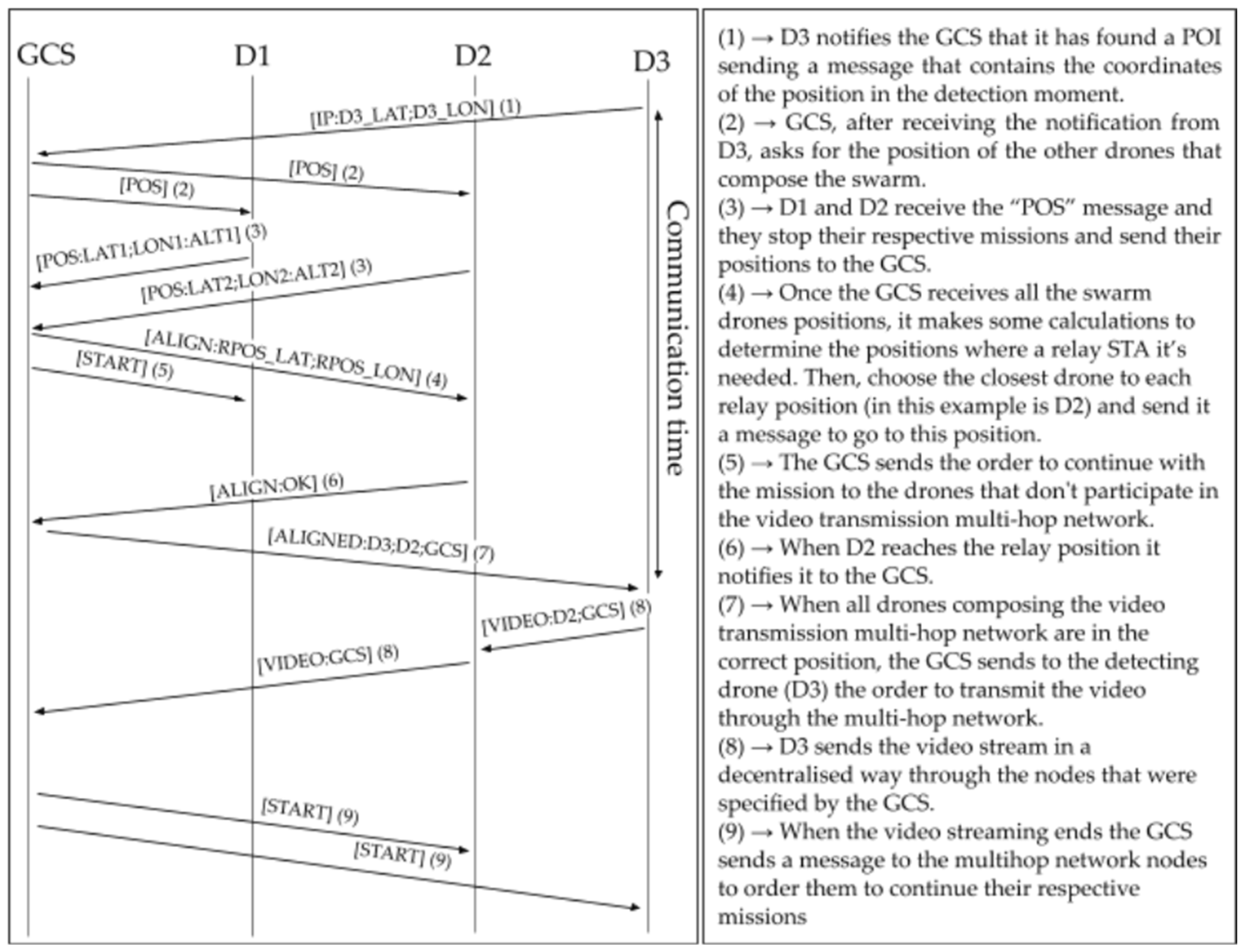
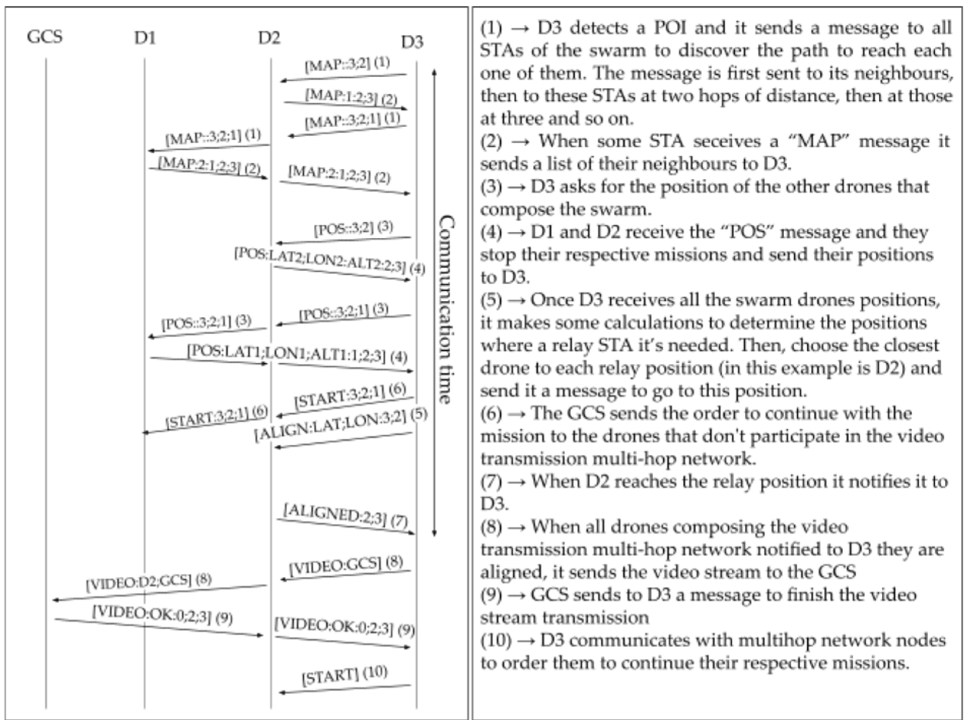
Figure 6 and
Figure 7 show the message sequence when a POI is detected for centralized and decentralized architectures, respectively. In the example, upon detection of a POI by drone D3, a two-hop data path is built, including drone D2 as a relay.
The different scenarios are referred to by three alphanumeric characters separated by a hyphen. The first character refers to the architecture used in the control communications; “C” means “centralized” and “D” means “decentralized”. The second one refers to the technology used for control communications (e.g., routing protocol signaling and telemetry), and the third stands for the technology used for video transmission. The second and third characters are either “6” or “H”, meaning Wi-Fi 6/6E and Wi-Fi HaLow, respectively. In a centralized architecture, the swarm is managed from the GCS, and control communications are built using one-hop links from each UAV to the GCS. Note that only Wi-Fi HaLow can guarantee this type of connectivity in this scenario due to its larger range. Conversely, in a decentralized architecture, the management is distributed, with the UAV finding the POI and the node setting up the multi-hop network (
Figure 1). Due to the nature of the centralized architecture, it has a limited coverage area, while decentralized approaches do not. As in a centralized architecture, all nodes have to be contained within the coverage of the central node (i.e., the ground control station), missions could not be larger than the communication range distance of the technology used for control communications. On the other hand, in decentralized architectures, this problem does not exist, and the size of the mission region can be extended as needed. However, wireless mesh networks often face scalability limitations due to interference and routing overhead. While the proposed architecture mitigates channel contention through a dual-radio design, which addresses one key bottleneck limiting throughput, very large deployments may still require additional scalability-enhancing mechanisms (e.g., see [
24]). Each scenario is defined below, along with its code, as follows:
C-H-6: Control communications use an IEEE 802.11ah radio (i.e., Wi-Fi HaLow) through a centralized architecture, while video transmissions use a Wi-Fi 6/6E radio to create a multi-hop path.
D-6-6: The vehicle carries only one Wi-Fi 6/6E interface, and control communications and swarm management are decentralized.
D-H-H: Communications are carried out by a single Wi-Fi HaLow interface, following a decentralized architecture.
C-H-H: Only one Wi-Fi HaLow radio is on board, with a centralized architecture.
The areas scanned under both aligning and non-aligning scenarios (cf.
Section 5.3) are 73.5 m wide, and the lengths range from 133 m to 530 m with intervals of 44.5 m (cf.
Figure 5). Although mission areas could be longer, this set of missions is diverse enough to study the behavior of the swarm when the distances and the number of UAVs grow. Note that, using Wi-Fi HaLow as the control channel interface, centralized architectures could cover areas within a 1 km radius from the GCS (i.e., covering distances more than 2 km apart). For decentralized scenarios, however, there is no limit as long as all nodes have at least one neighbor within range.
The simulations of dynamic scenarios (cf.
Section 5.3) were carried out by defining new missions with area lengths ranging from 530 m to 1.02 km with increments of 44.5 m. The POIs introduced were chosen in the same way as those of the original missions, placing one in each corner and the center of the last subregion of each mission (cf.
Figure 5). The maximum inspection area length is defined from the Wi-Fi 6/6E video transmission range (i.e., 200 m, which allows transmitting 17 Mbps) to ensure that there is always connectivity between neighbors through both interfaces.
The maximum inspection area length is determined by the coverage range of the video transmission interface, so that the video stream can be transmitted between neighbors regardless of the point where they are located inside their respective inspection areas. Thus, if we take the rectangle that forms the junction of two consecutive inspection areas, its diagonal must be equal to the video transmission range. The video transmission range for each wireless technology considered is derived from throughput-distance curves obtained through real-world measurements (cf.
Section 3). These measurements were conducted in a scenario that closely resembles the target application environment. More precisely, using omnidirectional antennas under line-of-sight (LoS) conditions in an open outdoor area, with occasional interference from distant networks. Additionally, a conservative approach was adopted when selecting the maximum transmission distances since we considered distances at which the measured throughput exceeded the video requirements. This ensures a margin of tolerance for deployment in scenarios with potentially less favorable conditions. When the network uses multiple channels (e.g., in the alternating strategy), frequency channels are allocated to avoid partially overlapping transmissions. Equation (3) defines the maximum length of the inspection area. The variable
rvideo is the video transmission range (i.e., 270 m for Wi-Fi HaLow and 200 m for Wi-Fi 6/6E, which offer 2.75 Mbps and 17 Mbps at such distances, respectively), while
W is the width of the mission area (i.e., 73.5 m). Applying Equation (3), maximum inspection area lengths of 130 and 93 m are obtained for scenarios using Wi-Fi HaLow and Wi-Fi 6/6E to transmit video, respectively.
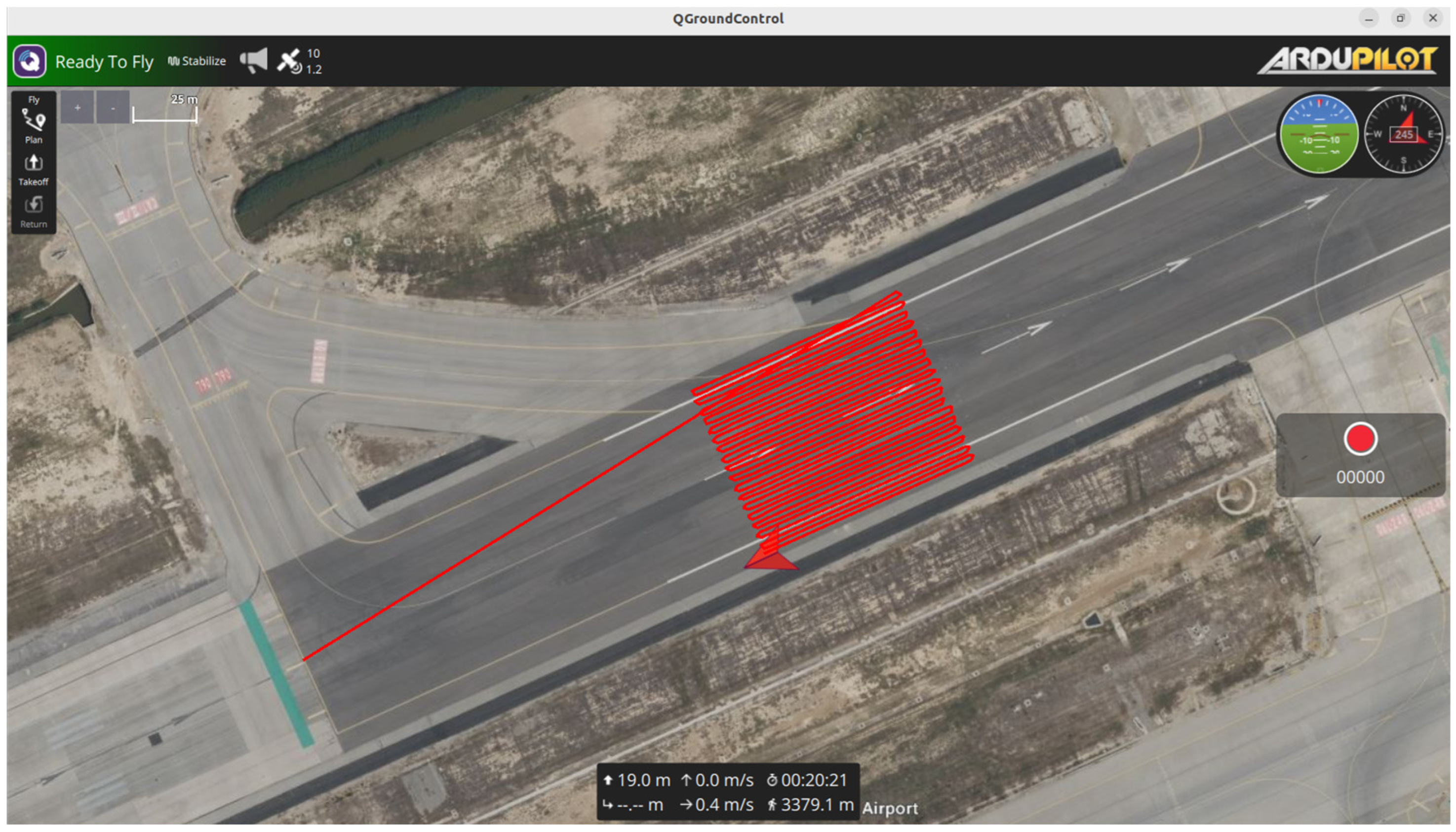
Inspection areas are surveyed by the UAVs in a one-directional grid with a separation between grid rows fixed to 2 m. The scanning is performed starting from the farthest corner on the left (observing from the home position) and finishes by the right inspection area edge, as shown in
Figure 8. If a UAV reaches critical battery levels, the flight mode would automatically switch from auto to return to launch (RTL). In that flight mode, the UAV returns to the takeoff position. If this occurs during a video transmission, the multi-hop network must be re-established.
All parameters are listed in
Table 1 along with their values, units and a description to facilitate understanding of the environment configuration.
5.3. Path Generation Strategies
We define and evaluate three different approaches to manage the missions and generate the communications path: aligning, non-aligning, and dynamic. Their differences are explained below.
In aligning scenarios, video transmission is conducted over a multi-hop network composed of pre-aligned UAV nodes. In this configuration, the active coordination node calculates the straight-line distance between the detecting UAV and the Ground Control Station (GCS), segmenting this distance into intervals corresponding to the effective video transmission range—270 m for Wi-Fi HaLow and 200 m for Wi-Fi 6. The resulting division points along the line connecting the detecting UAV and the GCS are defined as relay points. UAVs located in proximity to these relay points are then identified and commanded to relocate accordingly. Once all relay points are occupied, the network is considered formed, and video transmission is initiated.
In contrast, non-aligning scenarios are designed to reduce the time required for multi-hop network formation. In this approach, the node responsible for establishing the communication path first checks whether the detecting UAV is within direct transmission range of the GCS. If not, it searches among neighboring UAVs (i.e., those within the detecting UAV’s transmission range) for the one closest to the GCS. If this UAV is still outside the GCS’s transmission range, the process continues iteratively, as a new candidate is selected from the neighbors of the previously chosen UAV, and the search proceeds until a UAV capable of directly reaching the GCS is found. The selected nodes stop and act as a relay STA. This method forms the multi-hop path dynamically without requiring UAVs to reposition themselves to predefined relay points.
On the other hand, having an expression to calculate the network capacities (Equation (2) in
Section 4) made it possible to generate a multi-hop network that satisfies specific video quality demands. The capacity required by the quality demand is achieved by combining the Wi-Fi HaLow and Wi-Fi 6/6E interfaces. The use of the former is prioritized to minimize the multi-hop network length. For control communications of this scenario, a centralized architecture is chosen. These new strategies and functionalities give rise to dynamic scenarios.
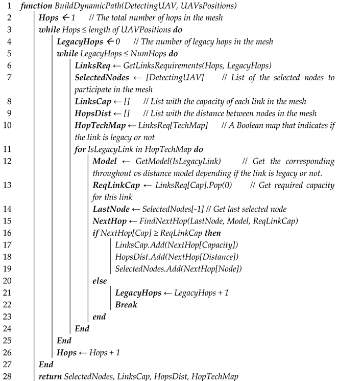
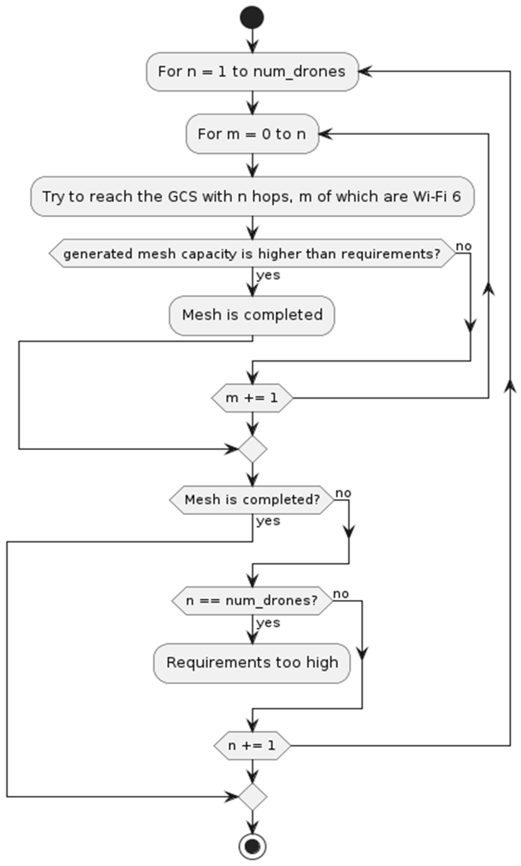
In dynamic scenarios, to resolve the multi-hop network, a brute force strategy was applied, which consisted of first testing solutions built of single-hop networks, and increasing the number of hops until a tested solution meets the requirements. This is represented in Algorithm A1 with the while loop contained between lines 6 and 21. This strategy was adopted because, before the generation of the network, it was not known how many hops it would take to reach the GCS. Therefore, the requirements to be met by the links are unknown, since the more hops, the more the bandwidth is distributed and the greater the individual link capacity needed. By defining the length of the network and the technology used in each hop, the capacity of the links is also defined. Line 9 in Algorithm A1, shows how, using the “GetLinksReq” function, the requirements for the links that compose the multi-hop network are obtained. It is then possible to start creating the network by searching for nodes that are located at a distance that allows the required throughputs to be achieved despite having to share the medium with adjacent links that use the same technology. In addition, for each number of nodes in the network, the different combinations of technologies had to be tested. So, tests were started with all links being Wi-Fi HaLow, and increased the number of Wi-Fi 6/6E links until the capacity requirements were met, unless the all-Wi-Fi6/6E link combination is still unable to fulfill the requirements. In that case, the mesh length is increased by one more hop and the process starts again (trying with all links being Wi-Fi HaLow and increasing the Wi-Fi 6/6E one by one until the requirements are met). The while loop between lines 8 and 20 of Algorithm A1, included in
Appendix A, illustrates how this is implemented in the code.
The complexity of the algorithm depicted in
Figure 9, which searches for the optimal combination of wireless technologies for each hop, grows as O(NumHops
2), where NumHops denotes the number of links in the data path. Thus, this algorithm becomes computationally expensive when the required number of hops grows. However, in the scenarios considered in this paper, the maximum number of hops reached in the largest mission is six. In this case, in which the required throughput is 3 Mbps, and six legacy hops are needed, the average time to find the solution was shorter than 3 s (cf.
Figure 9) when the algorithm was executed on a standard mid-range laptop acting as GCS.
Initially, the hops of both technologies were arranged in a segregated way, i.e., first the required Wi-Fi 6/6E hops were allocated on the detecting drone side, and then all the Wi-Fi HaLow hops were allocated next so that the last one had the GCS at one end. Then, the alternating strategy was implemented, in which the technologies used for each link of the multi-hop network are ordered. In this way, different links can use distinct channels and thus avoid interference.
Figure 10 shows both strategies. As can be seen, in the segregated strategy, the UAV that communicates with the GCS has to reuse the channel through which it receives, since transmission and reception are carried out through the same interface. When alternating, it can use different channels because reception is carried out through the IEEE 802.11ax interface.
6. Analysis of Results
This section analyzes the implemented scenarios to compare the communication architectures outlined earlier. The simulations record metrics such as coverage distance, time and energy consumption, and multi-hop network characteristics (node distance, participating nodes, and link throughput).
First, we discuss the communication time, which is the time the swarm needs to coordinate the video transmission. While we monitored other time-related metrics, such as total mission duration and time to detect the POI, these were deemed irrelevant to our study, which focuses on establishing the communication path. Moreover, none of the studied alternatives significantly impacted these metrics. After that, we analyze the capacity offered by the generated multi-hop networks for each scenario. Then, we compare the average multi-hop network length and finally, we evaluate the reductions in energy consumption achieved by each approach.
6.1. Communication Time
Communication time is defined as the time elapsed since a drone detects a POI until the swarm builds the multi-hop network through which the video stream is transmitted. Note that this work focuses on the initial delay associated with network formation, rather than the transmission delay of video over the established multi-hop network. For a detailed analysis of video transmission delay in Wi-Fi-based multi-hop networks, see [
25].
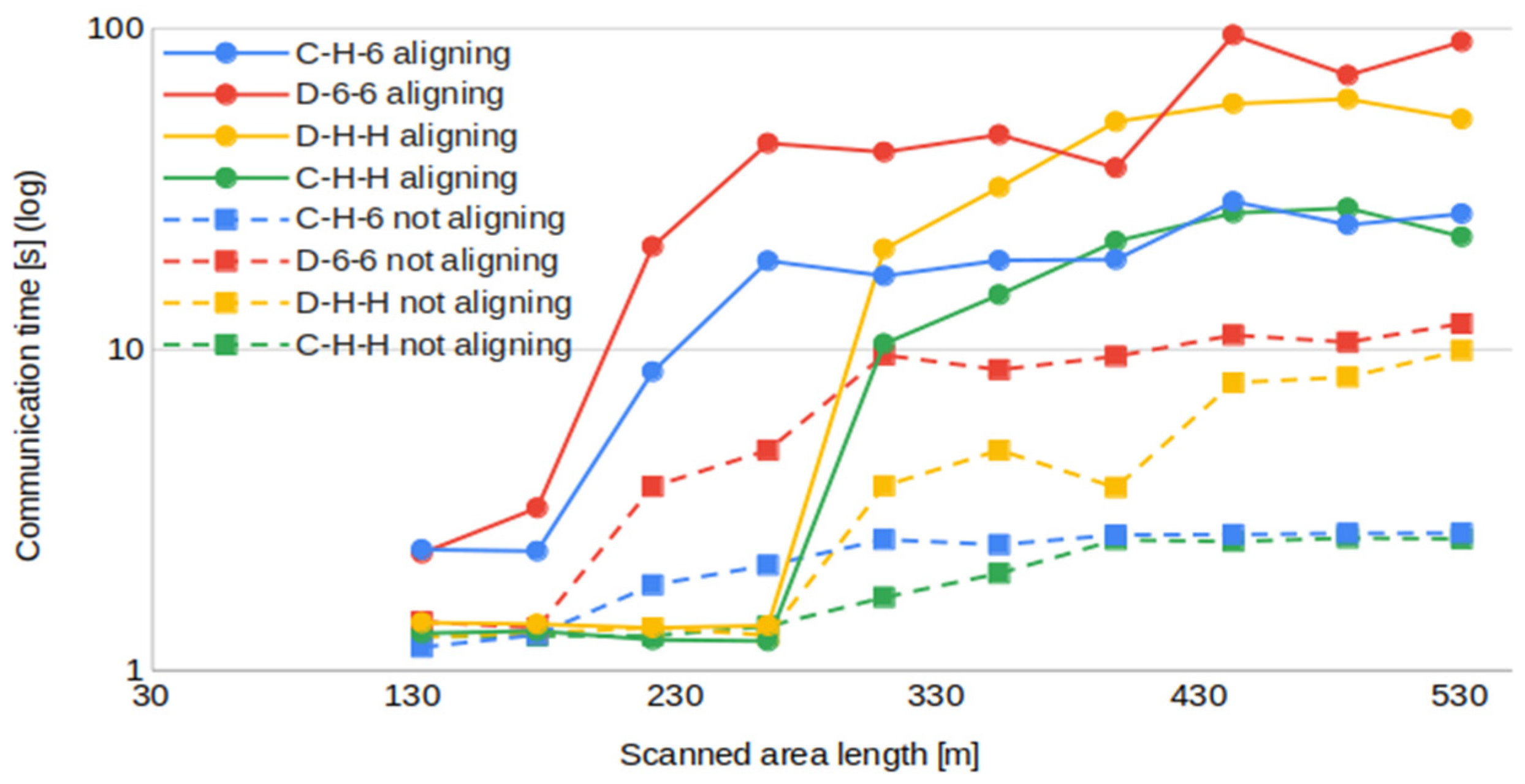
Emulation results show that the non-aligning method notably reduces the time spent to build the multi-hop network, thanks to avoiding unnecessary displacements (note that dashed lines correspond to the non-aligning approaches in
Figure 11). When alignment is used, the time invested fluctuates in ranges in the scale of tens of seconds, while not aligning reduces communication time below 10 s.
In general, centralized approaches are faster in building the multi-hop network due to the capability of the central node to reach all the other nodes in one hop. In the distributed architecture, a longer signaling exchange is needed to collect the necessary information to build the map of the mesh, which grows very fast when the number of nodes increases (
Figure 11).
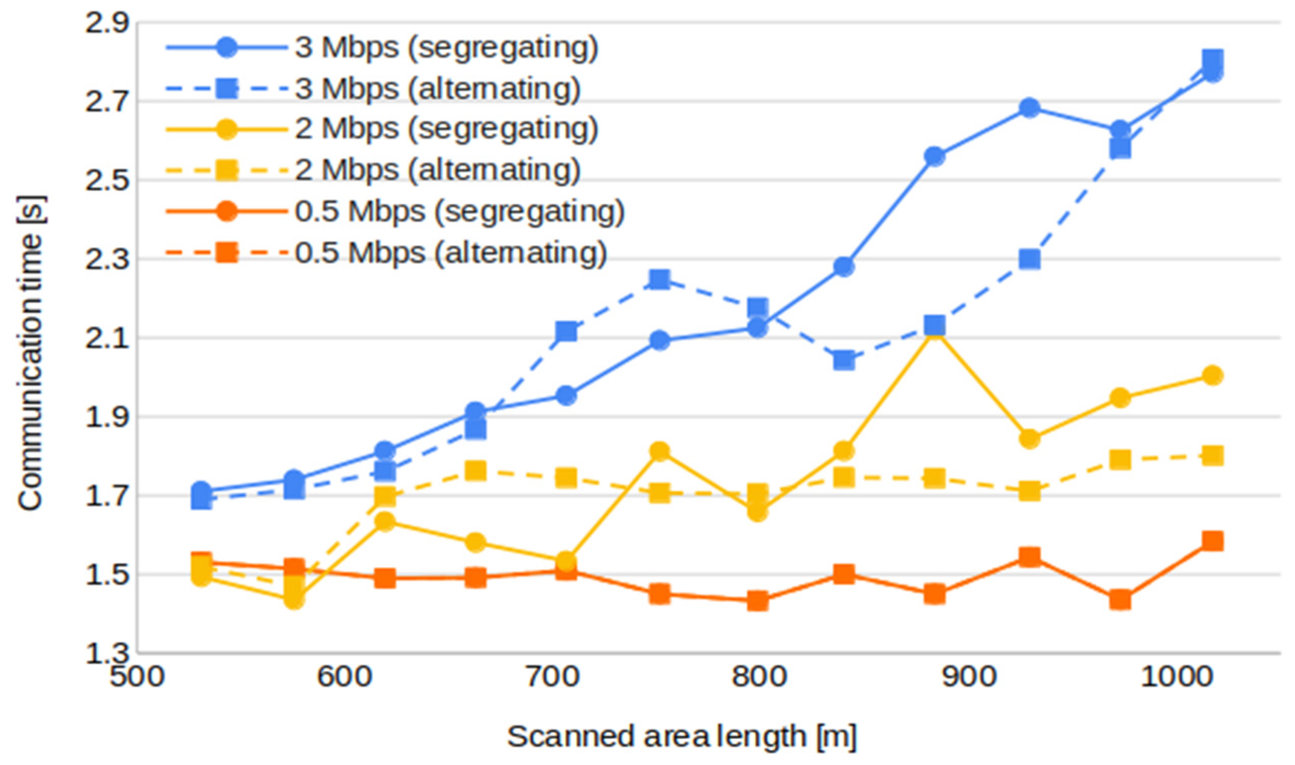
Figure 12 compares the communication time when the network is built to meet different throughput requirements (namely, dynamic scenarios). It shows that, as more capacity is required for the video transmission network, the greater the distance between the GCS and the detecting UAV, and longer communication times are measured. This occurs because the combination of these two factors (i.e., throughput and distance) results in networks with more hops. Recall that shorter links enable higher data rates. Hence, from a throughput perspective, networks with multiple short-distance links are preferable to those with fewer long-distance links. Therefore, the observed increase in communication time can be attributed to a greater number of hops. This phenomenon arises because, as the number of hops increases, the number of possible link ordering combinations also increases, leading to significantly larger computation times to find the optimal solution. This translates into higher delays in building the multi-hop video transmission network (i.e., in communication time).
6.2. Throughput
Here, we use the term throughput to refer to the capacity of the multi-hop network built upon discovering a POI, from finding the UAV to the GCS. Recall that this network function is to carry a video stream to allow the corresponding checks by the technician on the ground in charge of the operation supervision. For the throughput metric, a capacity is assigned to each link taking into account measurement results based on the distances and technologies employed between the nodes in the multi-hop network (cf.
Section 3). Once all links have been assigned a capacity, Equation (2) is applied to estimate the aggregate capacity of the multi-hop network.
The behavior of the capacity along the mission length is approximately the same in all non-dynamic scenarios. It starts at the maximum throughput and decreases as the mission length increases until it reaches a stable region where the throughput tends to a minimum value above 1 Mbps, which is always guaranteed because we limit the distances between UAVs surveying neighboring areas. This behavior agrees with the conclusions obtained in
Section 4 about multi-hop network capacity.
Figure 13 shows C-H-H and D-H-H multi-hop network capacity. For these scenarios, only small differences are present in transmissions at larger distances. Aligning strategies achieve a slightly higher capacity.
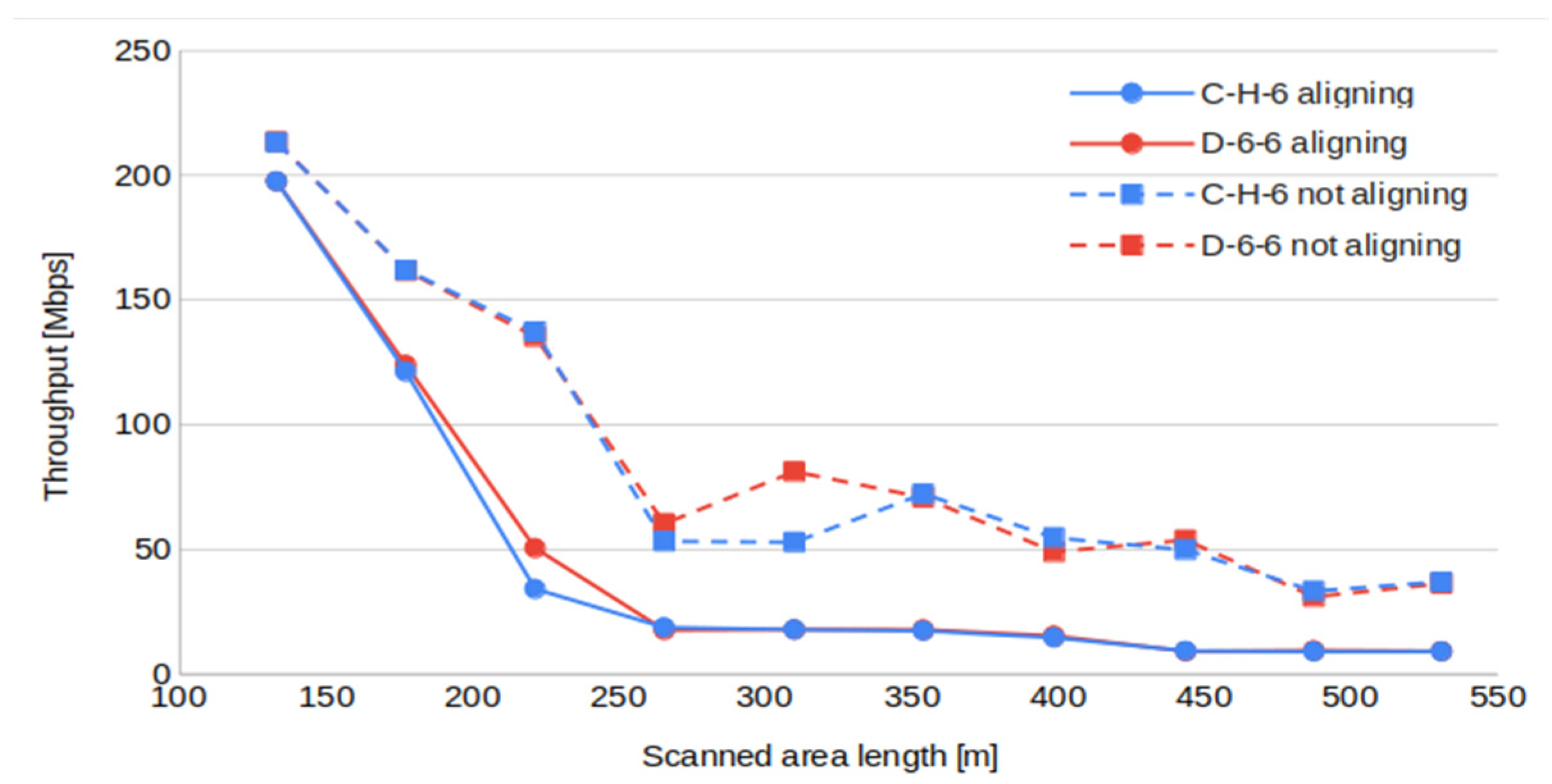
In C-H-6 and D-6-6 scenarios, the differences between aligning and not aligning are substantial (
Figure 14). It is clear that, without alignment, higher throughputs are measured. The average throughput for aligning scenarios is close to 45 Mbps for C-H-6 scenario and around 47 Mbps for the D-6-6. This approach enables ultra-high definition (UHD) video transmission as far as 250 m and high definition (HD) for even longer distances (
Table 2) [
26]. On the other hand, non-aligning scenarios achieve around 87 Mbps for C-H-6 and close to 90 Mbps for D-6-6. This approach ensures UHD video transmission in all cases.
We have to note that the performance of non-aligned topologies is more variable and harder to predict since it depends on the positions of the nodes when the POI is detected, while in the aligning case, the position of the relay nodes is deterministic.
The results may seem counterintuitive, since the alignment of UAVs provides homogeneous distances, avoiding excessively long links, causing a bottleneck in the path. Note, however, that all links, except the last one, are, by design, as long as the minimum video transmission can afford, reducing the total capacity of the mesh. Without alignment, the relay positions are determined hop by hop, finding the closest node to the GCS inside the video transmission range of the last found hop. This results in a mesh composed of links whose distances are, at most, the maximum range of video transmission, but, in most cases, several tens of meters shorter. In dynamic scenarios, throughput results are primarily influenced by the capacity requirements and, therefore, do not warrant in-depth analysis.
6.3. Number of Hops
The number of hops refers to the number of links formed by the UAV nodes participating in the multi-hop network to transmit the video stream.
The analysis starts with a comparison of aligning and non-aligning scenarios (
Figure 15). The non-aligning method focuses on reducing the time to build the mesh to transmit the video stream, but it increases the average number of hops to do it. Even so, the difference is not large.
For scenarios using Wi-Fi 6/6E for video transmission, the number of hops increases compared to those using Wi-Fi HaLow, since the range of the technology is shorter. On average, the scenarios with Wi-Fi 6/6E as video transmitter (VTX) technology use networks with 37% more hops than the scenarios where Wi-Fi HaLow is used.
Not-aligned networks require, on average, 10% more hops than those with aligned networks. This increment in the number of hops is because the sum of the link distances is larger than the distance between GCS and the detecting UAV, since the line joining all the nodes is not straight. For that reason, extra hops are sometimes needed to reach the GCS.
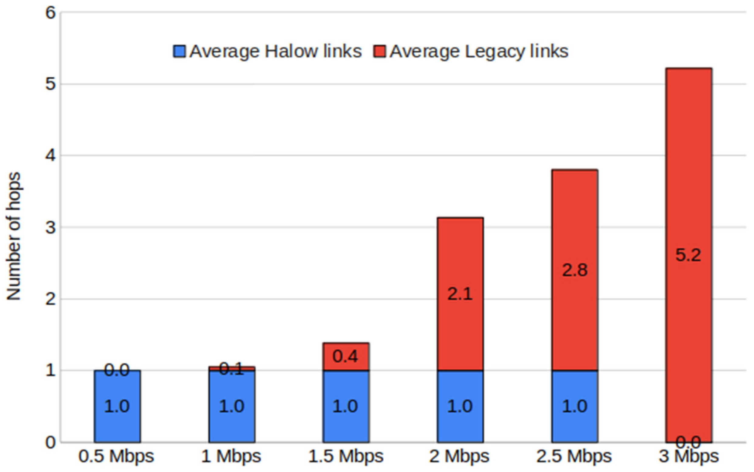
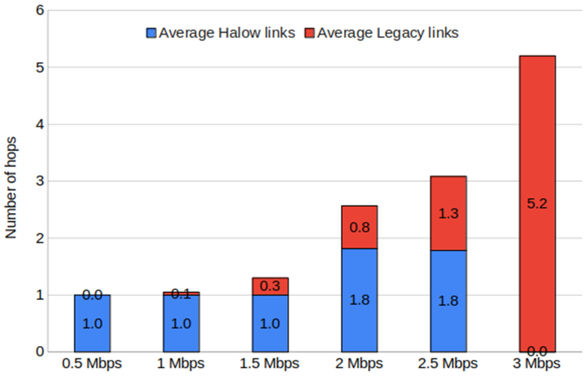
Next, an analysis of the impact of alternating or segregating the VTX technologies in the multi-hop network is carried out. These approaches are evaluated for required throughputs of 0.5, 1, 1.5, 2, 2.5 and 3 Mbps and have been represented by averaging all the missions (
Figure 16 and
Figure 17).
For a demand of 0.5, 1, 1.5 and 3 Mbps, no relevant difference in the number of hops is observed between alternating and segregating methods. In the former three, this is due to the fact that most distances can be covered with one or two hops. In the last one (3 Mbps), all links must be implemented with Wi-Fi 6/6E because the demand is above the maximum throughput offered by Wi-Fi HaLow. Interestingly, the cases with 2 and 2.5 Mbps requirements show significant differences and a notable increase compared with the 1.5 Mbps case. This is because increasing the minimum throughput to 2 Mbps means greatly reducing the coverage range of Wi-Fi HaLow links from 880 m to 500 m, and also due to the impossibility of chaining two consecutive Wi-Fi HaLow links, because of the resulting interference. For a demand of 2.5 Mbps, the alternating approach again shows better results, achieving the greatest advantage over the segregated approach. It is worth noting the difference in terms of the predominant technology in each case. For the segregating approach, more Wi-Fi 6/6E links are used, while in the alternating approach, Wi-Fi HaLow links predominate.
6.4. Energy Consumption
Energy consumption is a very important metric for any UAV application since the most restrictive condition at the moment of designing a flight plan is often the time the UAV can fly without running its battery out. For drones powered by Li-Po batteries, flight times typically range from several to tens of minutes, with the UAV motors being the primary source of energy consumption in the system. For this reason, the potential power savings from using Wi-Fi HaLow instead of a Wi-Fi legacy option are not particularly significant. In comparison, these savings would be negligible. However, by combining different Wi-Fi technologies, it is possible to decrease the amount of energy consumed by the swarm.
As a metric for energy consumption, we measure the difference between the energy used by the entire swarm when no POI is detected after surveying the area, and the energy consumed during a mission where a POI is discovered and the multi-hop network is established. This allows us to isolate the impact of different multi-hop network formation strategies on energy consumption.
An approximation of the extra battery consumption resulting from detecting a POI is calculated using values from communication time measurements and the number of hops of the multi-hop network. The expression used to calculate the extra battery consumption is presented in Equation (4), where C is the extra battery consumption, t
comm is the communication time, as defined in
Section 6.1, N is the total number of UAVs in the swarm, t
video is the duration of the video stream transmission, L
mesh is the number of nodes used to transmit the video, and P
avg is the UAV’s average power consumption, which in the Dronekit-SITL emulator has a value equal to 305 W.
The duration of the video stream is fixed at 10 s, according to the intended application (i.e., an airport runway survey in search of defects on its surface).
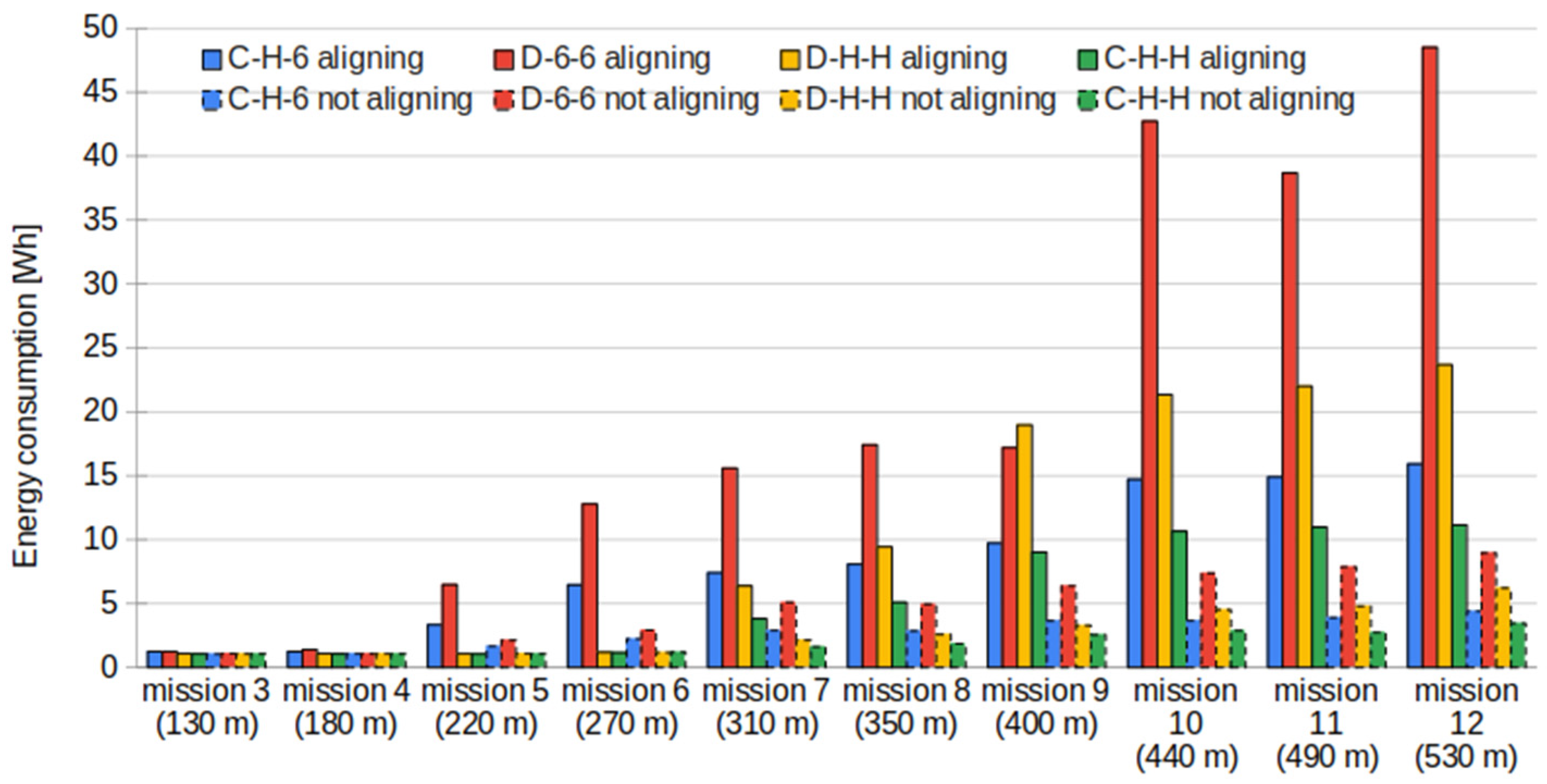
Thanks to reducing communication time, non-aligning scenarios outperform aligning scenarios in terms of power consumption (
Figure 18). The average energy consumption observed in the aligning scenarios was 11.15 Wh, while the non-aligning scenarios reduced the consumption to 3 Wh. In addition, when comparing scenarios with different architectures, centralized approaches obtain better results since this architecture reduces the communication time, as discussed in
Section 6.1.
The benefits of using dynamic scenarios are a combination of improvements in communication time and a reduction in the number of hops. Alternating wireless technologies at each hop improves the energy performance compared with segregating, thanks to the fact that it reduces the number of hops for large mission areas when demanding 2 Mbps (
Figure 19).
7. Conclusions and Future Work
In this work, we have discussed and compared various strategies for forming a multi-hop wireless network to enable high-quality video transmission between any UAV in a swarm and the GCS. The comparison includes delay, video bandwidth, number of hops and energy consumption metrics.
The first design choice involves the alignment of UAVs upon a POI detection to achieve a shorter-distance multi-hop network. However, our emulation-based results show that not aligning UAVs was faster and required less energy without sacrificing network throughput. Non-aligning strategies combined with centralized management of swarm communications gave rise to the best results. The scenarios with Wi-Fi 6/6E as VTX ensured good video quality for any distance, but often required more nodes in the multi-hop network than the scenarios with Wi-Fi HaLow as VTX. These statements highlight that intelligently combining long-range, slower Wi-Fi HaLow with short-range high-speed legacy Wi-Fi interfaces, as demonstrated in the dynamic scenarios, proved to be the most effective and efficient solution for the proposed use case. Alternating wireless technologies at each consecutive link in the video transmission path allows nodes to receive on one interface while transmitting on the other, resulting in higher throughput compared to the approach of grouping links in segregated clusters of the same wireless technology. Therefore, using two radios with different characteristics addressed the distance vs. rate trade-off. For cases where the consumption of communications hardware is relevant, we recommend using the HaLow radio as a wake-up mechanism to control the Wi-Fi 6 interface [
27]. This approach keeps the low-power HaLow radio active by default and activates the Wi-Fi 6 radio only when needed for video transmission, thereby reducing overall energy usage.
Another key contribution of this work is the demonstrated reduction in swarm energy consumption achieved through faster mission completion. Although the communication alternatives were studied on a specific use case (i.e., airport runway video survey) as a proof of concept, the contributions of this paper can be applied to other environments. Among the possible applications that can benefit from this contribution, we find search and rescue missions in contexts of natural disasters, forestry applications, inspection of solar panels, monitoring of agriculture, and more.
As future lines of research, we plan to analyze other aspects of the wireless mesh network. For example, the end-to-end packet delay and its dependence on the number of hops. In terms of coordination of the swarm, it would be convenient to design algorithms to distribute the inspection area more efficiently or add task assignment mechanisms that consider parameters such as the available battery of each drone or mission progress level.
Although the evaluated scenarios involve short data sessions with assumed stable channel conditions, other applications may require multiple video sources or extended streaming, where network overload or congestion is likely to occur. To improve robustness for a wider variety of applications, future work will focus on integrating dynamic mechanisms enabling the multi-hop network to adapt to varying configurations and channel conditions.
The implementation of the proposed solutions and the validation of the models with real UAV devices will be considered as future work. Although previous studies have analyzed throughput behavior in Wi-Fi-based multi-hop networks (e.g., see [
19]), their findings may not directly translate to the specific link dynamics and mobility patterns present in UAV multi-hop link interactions in practice.
Author Contributions
Conceptualization, G.B.-S., E.L.-A. and E.G.-V.; methodology, G.B.-S., E.L.-A. and E.G.-V.; software, G.B.-S.; validation, E.L.-A. and E.G.-V.; formal analysis, G.B.-S., E.L.-A. and E.G.-V.; investigation, G.B.-S., E.L.-A. and E.G.-V.; resources, G.B.-S.; data curation, G.B.-S., E.L.-A. and E.G.-V.; writing—original draft preparation, G.B.-S.; writing—review and editing, G.B.-S., E.L.-A. and E.G.-V.; visualization, G.B.-S.; supervision, E.L.-A. and E.G.-V.; project administration, E.L.-A. and E.G.-V.; funding acquisition, E.L.-A. and E.G.-V. All authors have read and agreed to the published version of the manuscript.
Funding
This research was funded in part by the Spanish MCIN/AEI/10.13039/501100011033/FEDER/UE through projects PID2019-106808RA-I00 and PID2023-146378NB-I00, and by Secretaria d’Universitats i Recerca del departament d’Empresa i Coneixement de la Generalitat de Catalunya with the grant number 2021 SGR 00330.
Data Availability Statement
The information is contained within the article.
Conflicts of Interest
The authors declare no conflict of interest.
Abbreviations
The following abbreviations are used in this manuscript:
| UAV | Unmanned Aerial Vehicle |
| GCS | Ground Control Station |
| POI | Point Of Interest |
| AODV | Ad hoc On-Demand Vector |
| PHY | Physical layer |
| RSSI | Received Signal Strength Indicator |
| LoS | Line of Sight |
| IoT | Internet of Things |
| MCS | Modulation Coding Schemes |
| MIMO | Multiple-Input Multiple-Output |
| BER | Bit Error Rate |
| MAVLink | Micro Air Vehicle Link |
| GUI | Graphical User Interface |
| UHD | Ultra-High Definition |
| HD | High Definition |
| VTX | Video Transmitter |
| RTL | Return To Launch |
| STA | Wi-Fi Station |
| AP | Wi-Fi Access Point |
| FANET | Flying Ad-Hoc Networks |
Appendix A
Algorithm A1 shows the pseudocode for the dynamic method instead of a block diagram, as shown in
Figure 9.
| Algorithm A1. Dynamic method |
![Drones 09 00584 i001 Drones 09 00584 i001]() |
References
- Fan, B.; Li, Y.; Zhang, R.; Fu, Q. Review on the Technological Development and Application of UAV Systems. Chin. J. Electron. 2020, 29, 199–207. [Google Scholar] [CrossRef]
- ICAO. Increased Use of Unmanned Aircraft Systems (UAS). 2024. Available online: https://www.icao.int/ (accessed on 2 June 2024).
- Javed, S.; Hassan, A.; Ahmad, R.; Ahmed, W.; Ahmed, R.; Saadat, A.; Guizani, M. State-of-the-Art and Future Research Challenges in UAV. Swarms IEEE Int. Things J. 2024, 11, 19023–19045. [Google Scholar] [CrossRef]
- Khan, S.; Zeeshan, M.; Ayaz, Y. Implementation and analysis of MultiCode MultiCarrier Code Division Multiple Access (MC–MC CDMA) in IEEE 802.11ah for UAV Swarm communication. Phys. Commun. 2020, 42, 101159. [Google Scholar] [CrossRef]
- IEEE Std 802.11ah-2016; IEEE Standard for Information Technology—Telecommunications and Information Exchange Between Systems—Local and Metropolitan Area Networks—Specific Requirements—Part 11: Wireless LAN Medium Access Control (MAC) and Physical Layer (PHY) Specifications Amendment 2: Sub 1 GHz License Exempt Operation. IEEE: New York, NY, USA, 2017; pp. 1–594. [CrossRef]
- IEEE Std 802.11ax-2021; IEEE Standard for Information Technology—Telecommunications and Information Exchange between Systems Local and Metropolitan Area Networks—Specific Requirements Part 11: Wireless LAN Medium Access Control (MAC) and Physical Layer (PHY) Specifications Amendment 1: Enhancements for High-Efficiency WLAN. IEEE: New York, NY, USA, 2021; pp. 1–767. [CrossRef]
- Ad hoc On-Demand Distance Vector (AODV). Routing RFC3561; Perkins: Santa Barbara, CA, USA, 2003. [Google Scholar]
- Alam, M.; Ahmed, N.; Matam, R.; Barbhuiya, F.A. IEEE 802.11ah-Enabled Internet-of-Drone Architecture. IEEE Int. Things Mag. 2022, 5, 174–178. [Google Scholar] [CrossRef]
- Chounos, K.; Maroulis, M.; Korakis, T. On the Involvement of IEEE 802.11ah Enabled Unmanned Aerial Vehicles (UAVs) in Emergency Networks. In Proceedings of the 2023 IEEE Conference on Standards for Communications and Networking (CSCN), Munich, Germany, 6–8 November 2023. [Google Scholar]
- Banerjee, S.; Misra, A. Minimum energy paths for reliable communication in multi-hop wireless networks. In Proceedings of the 3rd ACM International Symposium on Mobile Ad Hoc Networking & Computing (MobiHoc ’02) 2002; Association for Computing Machinery: New York, NY, USA; pp. 146–156.
- Bekmezci, I.; Sahingoz, O.K.; Temel, S. Flying Ad-Hoc Networks (FANETs): A survey. Ad Hoc Netw. J. 2013, 11, 1254–1270. [Google Scholar] [CrossRef]
- Sun, W.; Choi, M.; Choi, S. IEEE 802.11ah: A Long Range 802.11 WLAN at Sub 1 GHz. J. ICT Stand. 2013, 83–108. [Google Scholar] [CrossRef]
- George, A.S.; George, A.H. A review of Wi-Fi 6: The revolution of 6th generation Wi-Fi technology. Res. Inventy Int. J. Eng. Sci. 2020, 10, 56–65. [Google Scholar]
- LilyGo T-Halow. Official Manufacturer Shipping Website. Available online: https://lilygo.cc/products/t-halow?srsltid=AfmBOorQncOGa_3TQU33BvHdcJyvnb37Wcrzv3qCI2rBJM5Xp2Db2QE5 (accessed on 25 July 2025).
- T-Halow. Official Developer Technical Specifications. 2025. Available online: https://github.com/Xinyuan-LilyGO/T-Halow/blob/master/hardware/TX_AH/%E6%B3%B0%E8%8A%AF802.11ah%C2%A0TX-AH-Rx00P%20Series%20module%20technical%20specification_20231116174457.pdf (accessed on 25 July 2025).
- ESP32-S3 Datasheet. Espressif Official Datasheet. 2025. Available online: https://www.espressif.com/sites/default/files/documentation/esp32-s3_datasheet_en.pdf (accessed on 25 July 2025).
- Garcia, E.; Viamonte, D.; Vidal, R.; Paradells, J. Achievable bandwidth estimation for stations in multi-rate IEEE 802.11 WLAN cells. In Proceedings of the 2007 IEEE International Symposium on a World of Wireless, Mobile and Multimedia Networks, Espoo, Finland, 18–21 June 2007. [Google Scholar]
- NS-3 Official Website. 2024. Available online: https://www.nsnam.org/ (accessed on 30 June 2024).
- Frohn, S.; Gübner, S.; Lindemann, C. Analyzing the effective throughput in multi-hop IEEE 802.11 n networks. Comput. Commun. 2021, 34, 1912–1921. [Google Scholar] [CrossRef]
- Dronekit Project. Dronekit-SITL Official Website. 2024. Available online: https://dronekit-python.readthedocs.io/en/latest/develop/sitl_setup.html (accessed on 30 June 2024).
- MAVLink Official Website. 2024. Available online: https://mavlink.io/en/ (accessed on 30 June 2024).
- ArduPilot Official Website. 2024. Available online: https://ardupilot.org/mavproxy/ (accessed on 30 June 2024).
- QgroundControl Official Website. 2024. Available online: https://qgroundcontrol.com/ (accessed on 30 June 2024).
- Lei, L.; Tang, A.; Wang, X. Achieving scalable capacity in wireless mesh networks. Comput. Netw. 2024, 253, 110696. [Google Scholar] [CrossRef]
- Sanchez-Vital, R.; Gomez, C.; Garcia-Villegas, E. Exploring the boundaries of energy-efficient Wireless Mesh Networks with IEEE 802.11 ba. Int. Things 2024, 28, 101366. [Google Scholar] [CrossRef]
- Synopi. Bandwidth Required for HD FHD 4K Video Streaming. 2025. Available online: https://www.synopi.com/bandwidth-required-for-hd-fhd-4k-video (accessed on 4 March 2025).
- Lopez-Aguilera, E.; Demirkol, I.; Garcia-Villegas, E.; Paradells, J. IEEE 802.11-enabled wake-up radio: Use cases and applications. Sensors 2019, 20, 66. [Google Scholar] [CrossRef] [PubMed]
Figure 1.
Communication architectures used: (a) centralized; (b) decentralized.
Figure 1.
Communication architectures used: (a) centralized; (b) decentralized.
Figure 2.
Experimental throughput vs. distance curve for Wi-Fi 6/6E and HaLow in line of sight (LoS) outdoor links.
Figure 2.
Experimental throughput vs. distance curve for Wi-Fi 6/6E and HaLow in line of sight (LoS) outdoor links.
Figure 3.
Mesh capacity vs. mesh length in hops for networks with the last hop of 60 and 120 m.
Figure 3.
Mesh capacity vs. mesh length in hops for networks with the last hop of 60 and 120 m.
Figure 4.
Diagram of the scenarios’ emulation environment.
Figure 4.
Diagram of the scenarios’ emulation environment.
Figure 5.
Sketch of the regions, subregions and POI positions in the missions.
Figure 5.
Sketch of the regions, subregions and POI positions in the missions.
Figure 6.
POI detection communications for centralized architecture.
Figure 6.
POI detection communications for centralized architecture.
Figure 7.
POI detection communications for decentralized architecture.
Figure 7.
POI detection communications for decentralized architecture.
Figure 8.
Ground Control Station GUI screenshot showing one of the UAV’s flight paths during the mission (i.e., the red line).
Figure 8.
Ground Control Station GUI screenshot showing one of the UAV’s flight paths during the mission (i.e., the red line).
Figure 9.
Dynamic strategy block diagram, where n is the number of hops, num_drones is the total number of drones in the swarm and m is the number of Wi-Fi legacy hops in the multi-hop network.
Figure 9.
Dynamic strategy block diagram, where n is the number of hops, num_drones is the total number of drones in the swarm and m is the number of Wi-Fi legacy hops in the multi-hop network.
Figure 10.
Diagram representing segregating and alternating strategies.
Figure 10.
Diagram representing segregating and alternating strategies.
Figure 11.
Average communication time for scenarios C-H-6, D-6-6, D-H-H and C-H-H with aligning and not aligning methods in logarithmic scale.
Figure 11.
Average communication time for scenarios C-H-6, D-6-6, D-H-H and C-H-H with aligning and not aligning methods in logarithmic scale.
Figure 12.
Average communication time for dynamic scenarios with different throughput requirements. Note: the lines for 0.5 Mbps (i.e., orange lines) overlap.
Figure 12.
Average communication time for dynamic scenarios with different throughput requirements. Note: the lines for 0.5 Mbps (i.e., orange lines) overlap.
Figure 13.
Multi-hop network capacity for C-H-H and D-H-H aligning and non-aligning scenarios.
Figure 13.
Multi-hop network capacity for C-H-H and D-H-H aligning and non-aligning scenarios.
Figure 14.
Multi-hop network capacity for aligning and non-aligning methods in C-H-6 and D-6-6.
Figure 14.
Multi-hop network capacity for aligning and non-aligning methods in C-H-6 and D-6-6.
Figure 15.
Average number of hops for aligning (solid outline) and non-aligning (dashed outline) scenarios.
Figure 15.
Average number of hops for aligning (solid outline) and non-aligning (dashed outline) scenarios.
Figure 16.
Average number of hops for dynamic scenarios with different requirements and segregating technologies.
Figure 16.
Average number of hops for dynamic scenarios with different requirements and segregating technologies.
Figure 17.
Average number of hops for dynamic scenarios with different requirements and alternating technologies.
Figure 17.
Average number of hops for dynamic scenarios with different requirements and alternating technologies.
Figure 18.
Comparison between aligning (solid outline) and non-aligning (dashed outline) scenarios for extra battery consumption for POI detections.
Figure 18.
Comparison between aligning (solid outline) and non-aligning (dashed outline) scenarios for extra battery consumption for POI detections.
Figure 19.
Comparison between segregating (solid outline) and alternating (dashed outline) dynamic scenarios for extra battery consumption for POI detections.
Figure 19.
Comparison between segregating (solid outline) and alternating (dashed outline) dynamic scenarios for extra battery consumption for POI detections.
Table 1.
Parameters list.
Table 1.
Parameters list.
| Parameter | Value | Units | Description |
|---|
| pe | 0.06 | NA | Transmission error probability for each node beyond communication range |
| n | 5 | nodes | Number of nodes within the communication range |
| W | 73.5 | meters | Mission area width |
| rvideo | Wi-Fi HaLow | 270 | meters | Video transmission range for IEEE 802.11ah |
| Wi-Fi 6 | 200 | meters | Video transmission range for IEEE 802.11ax |
| lsmax | Wi-Fi HaLow | 130 | meters | Maximum area length for IEEE 802.11ah |
| Wi-Fi 6 | 93 | meters | Maximum area length for IEEE 802.11ax |
Table 2.
Required throughputs for different video resolutions [
26].
Table 2.
Required throughputs for different video resolutions [
26].
| Resolutions | Required Bandwidth (H264) | Required Bandwidth (H265) |
|---|
| 1280 × 720 (HD) | 3 Mbps | 1.5 Mbps |
| 1920 × 1080 (FHD) | 6 Mbps | 3 Mbps |
| 3840 × 2160 (UHD) | 25 Mbps | 12 Mbps |
| 4096 × 2160 (4K) | 32 Mbps | 15 Mbps |
| Disclaimer/Publisher’s Note: The statements, opinions and data contained in all publications are solely those of the individual author(s) and contributor(s) and not of MDPI and/or the editor(s). MDPI and/or the editor(s) disclaim responsibility for any injury to people or property resulting from any ideas, methods, instructions or products referred to in the content. |
© 2025 by the authors. Licensee MDPI, Basel, Switzerland. This article is an open access article distributed under the terms and conditions of the Creative Commons Attribution (CC BY) license (https://creativecommons.org/licenses/by/4.0/).
