Article

Combined Robust Control for Quadrotor UAV Using Model Predictive Control and Super-Twisting Algorithm

Department of Aerospace Engineering, College of Science and Technology, Nihon University, Chiba 274-8501, Japan
*
Author to whom correspondence should be addressed.
Drones 2025, 9(8), 576; https://doi.org/10.3390/drones9080576
Submission received: 17 July 2025 / Revised: 6 August 2025 / Accepted: 12 August 2025 / Published: 13 August 2025

Abstract

This paper proposes a robust control method of trajectory tracking for quadrotors under disturbance conditions, combining Model Predictive Control (MPC) and the Super-Twisting Algorithm (STA). MPC is a control strategy that solves an optimization problem by predicting the finite time future response from the model under control at each time step. However, MPC cannot guarantee control performance under disturbances such as modeling errors and wind gusts because it predicts future states of the control objects using a nominal model. To solve this problem, we propose a composite control method that uses Adaptive Super-Twisting Sliding Mode Disturbance Observer (ASTSMDO), which constrains the system to follow the MPC’s nominal model. The effectiveness of the proposed method is confirmed through numerical simulation. Compared to conventional MPC, the proposed controller achieves superior robustness and trajectory tracking performance under modeling error and wind disturbance.

1. Introduction

In recent years, unmanned aerial vehicles (UAVs) have attracted significant attention across a wide range of fields. In particular, quadrotor UAVs, which utilize four rotors, have become increasingly popular in applications such as cargo transportation and disaster area monitoring due to their ability to hover and perform vertical takeoff and landing (VTOL), their simple mechanical structure, and low maintenance costs [1,2,3,4]. The autonomous flight of quadrotor UAVs requires precise and coordinated control of all four rotors, making the implementation of a high-performance flight controller essential.
Trajectory tracking control is one of the most critical and challenging missions in flight control. To address this task, flight controllers based on PID (Proportional–Integral–Derivative) control [5,6] have been widely employed. Due to its simple theoretical foundation and ease of implementation, the PID controller has gained widespread popularity. However, it suffers from certain drawbacks, such as difficulty in parameter tuning and a lack of guaranteed optimality. Also, the backstepping method [7,8], based on Lyapunov stability theory, can gradually stabilize a nonlinear system by decomposing it into subsystems. However, this approach requires the tuning of a large number of parameters, making the design process complex and heavily reliant on the designer’s expertise.
As alternatives, representative optimal control methods such as the Linear Quadratic Regulator (LQR) [9] and Model Predictive Control (MPC) [10,11,12,13,14,15] have been proposed. LQR is based on infinite-horizon optimization and is designed under the assumption of convergence to a fixed target value. Consequently, when applied to time-varying reference trajectories such as circular trajectories, LQR requires frequent updates of the reference point. This leads to discontinuities in the control input and makes smooth tracking difficult. In contrast, MPC is a finite-horizon optimal control approach that allows for sequential determination of control inputs by predicting future reference trajectories. One of its notable features is the ability to explicitly impose constraints on both state variables and control inputs, enabling optimal control based on performance indices. Furthermore, recent studies [13] have reported that advancements in compact and high-performance computing hardware have made it possible to implement computationally demanding MPC in real time, leading to improvements in control performance. MPC also allows time-domain response shaping and offers easier tuning compared to PID controllers. However, in practical systems such as quadrotors, modeling errors and unknown disturbances are often present. Unless robustness against such uncertainties is enhanced, the control performance of MPC may degrade significantly.
Many researchers have proposed methods to improve the robustness of the MPC method [15,16,17,18,19]. Min–max MPC [15] and H-Infinity MPC [16] demonstrate robustness by solving an optimization problem that minimizes the worst-case effect of disturbances but cannot be applied to fast systems such as quadrotors because of the large computational load. H-infinity MPC can be solved using linear matrix inequality (LMI), but the underlying theory is mathematically intricate. The method that combines MPC and Model Reference Adaptive Control (MRAC) [17] achieves robust tracking performance under external disturbances by tuning the adaptive parameters such that the system output follows the reference trajectory generated by the MPC model. Nevertheless, a well-known drawback of MRAC is that increasing the adaptation speed often induces high-frequency oscillations in the control input, thereby compromising robustness.
The method [18,19] that combines MPC and Sliding Mode Control (SMC) has been studied to overcome the problem regarding robustness. SMC has excellent robustness against disturbances applied in the same channel as the control input by constraining the state quantities to the switching hyperplane in phase space. However, chattering in the control input results in a severe deterioration of control performance because it contains high-frequency oscillations near the switching hyperplane. Many techniques have been proposed to suppress chattering. For example, saturation functions are used to make the control input continuous. It should be noted that robustness against disturbances is poor because the constraint to keep state variables on the hyperplane is weak [20]. On the other hand, Super-Twisting Sliding Mode Control (STSMC) [21,22,23,24,25], which is one of the Higher-Order Sliding Mode Controls (HOSMC) proposed by Levant, simultaneously drives the first- and second-order switching functions to zero. Moreover, using a continuous function for the switching law suppresses chattering in the control input. However, large gains in the case of an unknown bound on the disturbance gradient can cause unnecessary control effort and chattering. Shtessel et al. [25] proposed adaptive STSMC to overcome these drawbacks by adapting the gain in response to bounded disturbances with unknown boundaries.
Furthermore, in scenarios such as cargo transport, system parameters like mass can vary, resulting in model errors. Under these circumstances, adaptive STSMC tends to conservatively select high gains by assuming worst-case conditions, which leads to overshoot and degraded control performance due to inefficient control inputs. In this regard, disturbance observer-based rejection is less prone to excessive compensation since it relies on estimating and compensating for disturbances.
The observer-based Super-Twisting Sliding Mode Disturbance Observer (STSMDO) [26,27,28,29,30] is a type of disturbance observer that exhibits high robustness against nonlinear disturbance and persistent disturbances such as model errors. Conventional disturbance observers are prone to performance degradation in the presence of model inaccuracies. In contrast, STSMDO, while utilizing system models, has a nonlinear structure based on sliding mode control that enables it to effectively compensate for disturbances and model uncertainties. It also offers the advantages of reduced chattering and improved estimation accuracy compared to conventional Sliding Mode Disturbance Observers [28]. In recent years, studies have proposed neural network-based disturbance observers [31]. These observers are capable of accurately approximating unknown uncertainties by learning from input–output data. However, they typically require a large number of hidden neurons, complex activation functions, and numerous adaptive weights. As a result, the computational burden increases significantly, and the overall control structure becomes more complex. Therefore, this study introduces the Adaptive Super-Twisting Sliding Mode Disturbance Observer (ASTSMDO), which features a simpler structure and lower computational burden compared to neural observers, while also being capable of adapting to unknown disturbance environments.
This study proposes a quadrotor flight controller that combines MPC and Adaptive STSMDO. In the proposed method, the MPC is designed by linearizing the nonlinear dynamics of the quadrotor using the Dynamic Inversion (DI) method [32,33]. The Adaptive STSMDO is applied to prevent degradation of the MPC’s control performance due to unknown wind disturbances and parameter uncertainties caused by variations in mass, which cannot be canceled by the DI method. Finally, numerical simulations of the quadrotor are conducted to verify the effectiveness of the proposed method. This study builds upon our previous work [34], which focused on robustness against wind disturbances, by further introducing compensation for parameter uncertainties using ASTSMDO. In the proposed framework, trajectory tracking is governed by MPC, while external disturbances and model uncertainties are estimated and compensated through ASTSMDO. The observer is designed based on the Super-Twisting algorithm, enabling finite-time convergence and high robustness to unmodeled dynamics. This integration enhances theoretical consistency in the disturbance rejection mechanism while maintaining a compact control structure. As a result, the proposed method achieves significantly improved tracking performance under both external disturbances and internal model uncertainties.

2. Dynamics of Quadrotor UAV

Figure 1 shows the coordinate system and parameters of the quadrotor UAV [2] that is the object of control in this study.
The equations of motion for translation and rotation in the body coordinate system are shown in the following equations.
m q + m q V ˙ B + m q + m q ω × V B = T B + F d + W g m q + m q g + F w
J ω ˙ + ω × J ω = M + M w
where V B = U V W T and ω = P Q R T are the velocity vector and the angular velocity vector in the body coordinate system, m q is the quadrotor’s mass, m q is the variation in quadrotor’s mass, J = d i a g ( J x x , J y y , J z z ) is the inertia tensor, T B = 0 0 T T and M = M x M y M z T are the input force vector and the input torque vector in the body coordinate system, F d = k d V B is the drag vector in the body coordinate system, k d is the air drag coefficient, W g = s i n θ si n ϕ co s θ co s ϕ co s θ T is the gravity component in the body coordinate system, g is the gravitational acceleration, and F w and M w are the unknown wind disturbance acting on translation and rotation in the body coordinate system.
The translational and rotational equations of motion in Equations (1) and (2) are expressed in the inertial coordinate system using the following equations:
x ˙ E = R E / B V B
η ˙ = Φ η ω
where x E = X Y Z T and η = ϕ θ ψ T are the position vector and the Euler angle vector in the inertial coordinate system. The coordinate transformation matrix R E / B from the body coordinate system to the inertial coordinate system and the Euler angle matrix Φ ( η ) are shown in the following equations.
R E / B = co s θ co s ψ si n ϕ si n θ co s ψ co s ϕ si n ψ co s ϕ si n θ co s ψ + si n ϕ si n ψ co s θ si n ψ si n ϕ si n θ si n ψ + co s ϕ co s ψ co s ϕ si n θ si n ψ si n ϕ co s ψ si n θ si n ϕ co s θ co s ϕ co s θ
Φ η = 1 si n ϕ t a n θ co s ϕ t a n θ 0 co s ϕ si n ϕ 0 si n ϕ / co s θ co s ϕ / co s θ
Thus, the equations of motion for translation and rotation in the inertial coordinate system are expressed as follows:
m q + m q x ¨ E = m q + m q R ˙ E / B V B R E / B ω × m q + m q V B + R E / B T B + R E / B F d + R E / B W g m q + m q g + R E / B F w
η ¨ = Φ ˙ η ω + Φ η J 1 ω × J ω + J 1 M + J 1 M w
The quadrotor’s thrust f i = f 1 f 2 f 3 f 4 T is expressed as follows:
f 1 = T 4 + M y 2 L b M z 4 d f 2 = T 4 M y 2 L + b M z 4 d f 3 = T 4 + M y 2 L b M z 4 d f 4 = T 4 M y 2 L + b M z 4 d
where L is the length of the arm. The coefficients b and d represent the lift and drag characteristics of the propeller, determined by its shape and other influencing factors.
Assuming that the thrust is proportional to the square of the propeller speed, the propeller speed ω i = ω 1 ω 2 ω 3 ω 4 T is calculated backwards from the following equation.
f i = b ω i 2
From the above, the propeller speed of the quadrotor is determined. However, there is a delay between the commanded speed ω i c o m from the controller and the actual speed ω i when the speed is transmitted from the computer to the actuator. In this study, numerical simulation is performed with this delay as a first-order time delay expressed by the following equation.
ω i = 1 T c s + 1 ω i c o m
where T c is the time constant of the actuator.
Therefore, the input force and the input torque considering quadrotor dynamics are as follows:
T M x M y M z = b b b b 0 L b 0 L b L b 0 L b 0 d d d d ω 1 2 ω 2 2 ω 3 2 ω 4 2
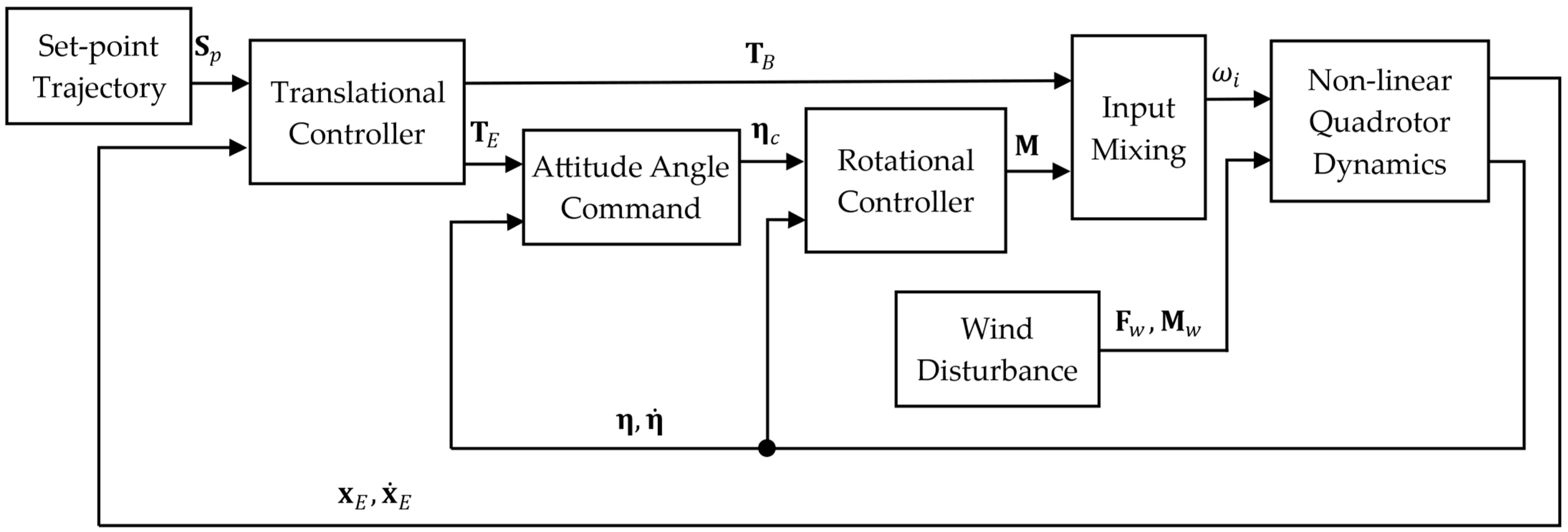
A block diagram of the proposed flight control system for the quadrotor UAV is shown in Figure 2.

3. Controller Design

3.1. Dynamic Inversion Method

The Dynamic Inversion method [32,33] linearizes nonlinear dynamics using estimated nonlinear terms. It is not required to change gains according to flight condition. The nonlinear terms except the unknown wind disturbance are linearized in the proposed method.
The input force vector T E = T X T Y T Z T is expressed as follows:
R E / B T B = T E
If the pseudo force vector is u t in the inertial coordinate system and the pseudo input moment vector is u r , the input force vector and the input torque vector are expressed as follows:
T E = m q ( R ˙ E / B V B + R E / B ω × V B R E / B F d / m q R E / B W g g + u t )
M = J Φ η 1 Φ ˙ η ω + Φ η J 1 ω × J ω + u r
Equations (7) and (8) are expressed by the following equation using Equations (14) and (15):
x ¨ E = u t + d t
η ¨ = u r + d r
where the matched disturbances d t and d r are shown below.
d t = 1 m q + m q R E / B F w + m q m q + m q u t + R ˙ E / B V B R E / B ω × V B + R E / B W g g
d r = Φ η J 1 M w
where d t represents the parameter variation as equivalent to the disturbance applied to the system.
Therefore, the equation of state is shown below.
d d t x E x ˙ E = 0 3 × 3 I 3 × 3 0 3 × 3 0 3 × 3 x E x ˙ E + 0 3 × 3 I 3 × 3 u t + 0 3 × 3 I 3 × 3 d t
d d t η η ˙ = 0 3 × 3 I 3 × 3 0 3 × 3 0 3 × 3 η η ˙ + 0 3 × 3 I 3 × 3 u r + 0 3 × 3 I 3 × 3 d r
Equations (20) and (21) are expressed by the following continuous time equations of state for the translational and rotational control systems, which have the same controller design method.
x ˙ t = A c x t + B c u t + B c d t
where A c R n × n is the continuous time system matrix, B c R n × m is the continuous time input matrix, x R n is the state vector, u R m is the control input vector, and d R m is the matched disturbance.
The discrete time equations of state are expressed as follows:
x k + 1 = A x k + B u k + B d k
where A R n × n is the discrete time system matrix and B R n × m is the discrete time input matrix.
The control input vector u is expressed as follows:
u = u m p c d ^
where u m p c is the MPC’s control input vector and d ^ is the ASTSMDO’s estimated disturbance.
The attitude angle command value η c = ϕ c θ c ψ c T is expressed using Equation (13), as follows:
cos θ c cos ψ sin ϕ c sin θ c cos ψ cos ϕ c sin ψ cos ϕ c sin θ c cos ψ + sin ϕ c sin ψ cos θ c sin ψ sin ϕ c sin θ c sin ψ + cos ϕ c cos ψ cos ϕ c sin θ c sin ψ sin ϕ c cos ψ sin θ c sin ϕ c cos θ c cos ϕ c cos θ c 0 0 T = T X T Y T Z
where ψ c = 0 , and solving for ϕ c ,   θ c , the following expression is obtained.
η c = ϕ c θ c ψ c = tan 1 T X cos θ c sin ψ T Y cos θ c cos ψ T Z tan 1 T X cos ψ + T Y sin ψ T Z 0

3.2. Model Predictive Control

Assuming that the ideal reference trajectory is r when following the set-point trajectory, s p approaches exponentially, as is shown by the following equation [14].
r k + i | k = s p k + i e x p i T s / T r e f s p k z k
where T s is the sampling time, T r e f is the time constant of the reference trajectory, and z R n is the control output vector shown below.
z k = C x k
where C R m × n is the control matrix. The reference trajectory T from the window parameter H w to the predicted horizon H p is given by
T k = S p k Λ e k
where Λ , T , S p and, e are expressed by the following equation.
Λ = d i a g e x p H w T s / T r e f e x p H p T s / T r e f T k = r T k + H w | k r T k + H p | k T S p k = s p T k + H w | k s p T k + H p | k T e k = s p T k | k z T k | k s p T k | k z T k | k T
where e R m ( H p H w 1 ) × 1 .
The MPC’s control input u m p c varies from the k step until the control horizon H u step and then becomes a constant value expressed in the following equation using the MPC’s control input change Δ u ^ m p c .
u ^ m p c k + i 1 | k = Δ u ^ m p c k + i 1 | k + + Δ u ^ m p c k | k + u m p c k 1 , i < H u u ^ m p c k + i | k = Δ u ^ m p c k + H u 1 | k , H u i
where ^ is the predicted value.
It is assumed that the unknown disturbance B d k in Equation (23) cannot be predicted. The predicted state space model using Equation (23) without B d k and Equation (31) is expressed as
x ^ k + i | k = A i x k + A i 1 + + A + I B Δ u ^ m p c k k + + B Δ u ^ m p c k + i 1 k + A i 1 + + A + I B u m p c k 1 , i < H u A i x k + A i 1 + + A + I B Δ u ^ m p c k | k + + A i H u + + A + I B Δ u ^ m p c k + H u 1 k + A i 1 + + A + I B u m p c k 1 , H u i
The matrix and vector forms of (32) are shown below.
x ^ k + H w | k x ^ k + H p | k = A H w A H p x k + i = 0 H w 1 A i B i = 0 H p 1 A i B u m p c k 1 + i = 0 H w 1 A i B 0 i = 0 H u 1 A i B i = 0 H w 1 A i B i = 0 H p 1 A i B i = 0 H p H u A i B Δ u ^ m p c k | k Δ u ^ m p c k + H u 1 | k
Equation (33) is summarized as follows:
X ^ k = Ψ x k + Υ u m p c k 1 + Θ Δ U ^ m p c
Thus, the predicted control output Z k is as follows:
Z k = C 0 0 C X ^ k
The following evaluation function is defined to solve the constrained optimization problem:
min Δ U ^ m pc k Z k T k T Q Z k T k + Δ U ^ m p c T k R Δ U ^ m p c k
where Q and R are the following weight matrices.
Q = d i a g q w H w q w H w + 1 q w H p
R = d i a g r w 0 r w 1 r w H u 1
The MPC’s control input change Δ u ^ m p c at the k step is shown below using the time series data of the MPC’s control input change Δ U ^ m p c k .
Δ u ^ m p c k = I 0 0 Δ U ^ m p c k
Therefore, the optimal control input at the k step is as follows:
u m p c k = Δ u ^ m p c k + u m p c k 1

3.3. Adaptive Super-Twisting Sliding Mode Disturbance Observer

MPC relies on an accurate nominal model and may still suffer performance degradation in the presence of significant modeling errors and wind disturbances. To address this, the proposed method introduces the Adaptive Super-Twisting Sliding Mode Disturbance Observer (ASTSMDO), which estimates modeling errors and wind disturbances in real time, enabling effective feedforward compensation [21,27].
The STSMDO’s state predictor is designed as follows:
x ^ ˙ o t = A c x ^ o t + B c u t + B c d ^ t + α 1 σ s g n σ
d ^ ˙ t = α 2 s g n σ
where ^ is the estimate, e o = x x ^ o is the error equation, d ^ is the estimated disturbance, and α 1 , α 2 are positive adaptive gains. The switching function σ is expressed as
σ t = S e o t
where S is the slope of the switching function.
The Super-Twisting Algorithm uses a continuous function σ for the switching function, so the state vector converges to the origin of the switching function without generating chattering. The adaptive gains [25] α 1 = α 11 α 1 i T and α 2 = α 21 α 2 i T at i = 1 , , m are defined using σ = σ 1 σ i T as follows:
α ˙ 1 i t = κ 1 s g n σ i μ i f   α 1 i > α m κ 2 i f   α 1 i α m
α 2 i t = λ α 1 i t
where κ 1 , κ 2 , α m , and λ are arbitrary positive constants.
The adaptive law is designed so that the switching function σ i converges within a threshold μ , by using a gain κ 1 that allows the adaptive gain to vary. In addition, when α 1 i falls below a lower limit α m , a gain κ 2 is applied to maintain α 1 i at a constant level. This adaptive mechanism ensures that the switching function σ i = σ ˙ i = 0 is achieved.
A block diagram of the proposed control method is shown in Figure 3, and the general procedure for calculating the control input of the proposed control method is shown in Algorithm 1.
Algorithm 1. Proposed control method.
   1 :   Obtain   the   set - point   trajectory S p
   2 :   Solve   the   MPC   optimization   problem   to   obtain   u m p c .
   3 :   Estimate   the   state   predictor   x ^ o
   4 :   Calculate   the   ASTSMO   switching   function   σ   using   the   error   e o = x x ^ o .
   5 :   Calculate   the   Adaptive   gains   α 1 , α 2   using   the   ASTSMO   switching   function   σ .
   6 :   Generate   the   ASTSMO   estimation   d ^ .
   7 :   Compute   the   sum   control   input   u = u m p c d ^ .
   8 :   Calculate   the   final   control   input   T E   or   M . using the Dynamic Inversion method
   9 :   Apply   T E   or   M to the quadrotor.
  10: Proceed to the next step.

4. Numerical Simulation

In this section, to confirm the effectiveness of the proposed method in numerical simulations, the quadrotor is subjected to wind disturbances using the Dryden model [35] shown in Figure 4, and the mass is increased by 2 kg, assuming cargo transport as a model error. Numerical simulations are conducted using MATLAB R2024b.
Table 1 shows the parameters of the quadrotor UAV. Although the proposed method has difficulty suppressing unmatched disturbances such as large time delays, time delay cannot be neglected in the dynamics of the quadrotor. Therefore, its effect is evaluated numerically rather than analytically.
Table 2 shows the parameters of controller and observer. The quadrotor is an underactuated system with four control inputs for six degrees of freedom. As a result, attitude control must precede position control to achieve motion in the desired direction. The controller parameters listed in Table 2 are designed with this structural constraint in mind. In the MPC framework, the predictive horizon H p is selected to reflect the fact that the rotational dynamics respond more quickly than the translational dynamics. The control horizon H u is set to approximately 20–30% of the predictive horizon H p , providing a reasonable balance between control performance and computational cost. The weighting matrix Q , R is also designed similarly to the Linear Quadratic Regulator, based on the dynamic response characteristics of the quadrotor. In the ASTSMDO framework, the switching function is defined based on the condition without disturbances, and the controller is designed so that the value of the switching function returns to the threshold value μ when disturbances are applied.
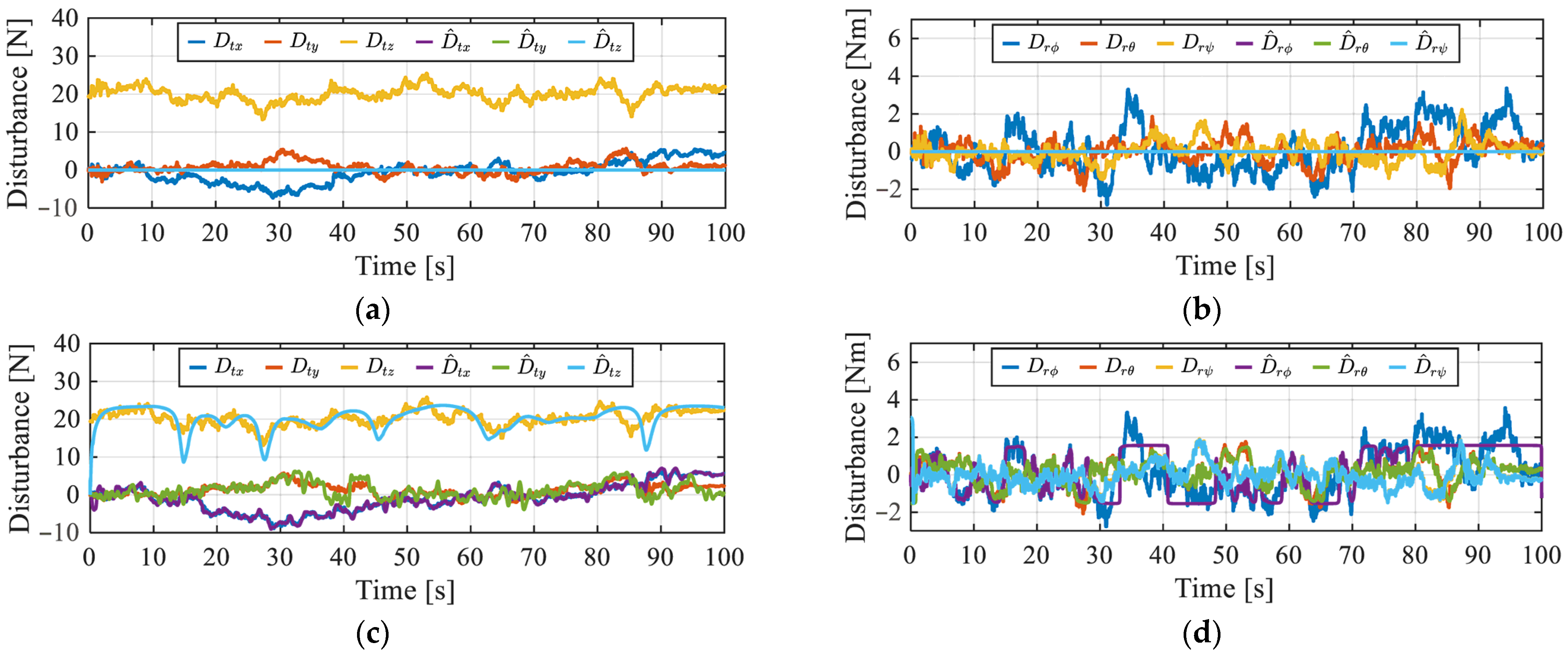
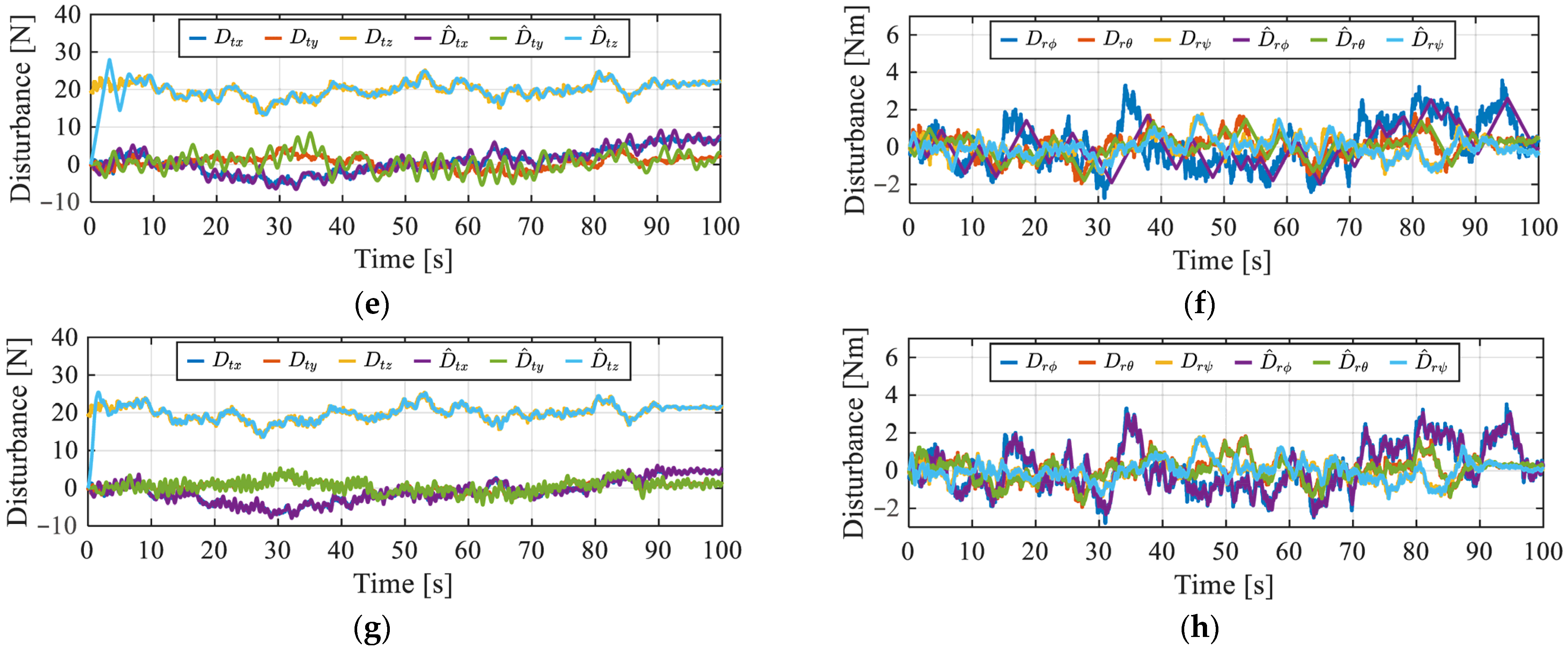
In numerical simulations, the effectiveness of the ASTSMDO in rejecting disturbances is demonstrated by comparing the actual external disturbance. The translational disturbance D t and rotational disturbance D r acting on the quadrotor are expressed as follows:
D t = m q + m q d t
D r = J d r
The translational disturbance estimates D ^ t and rotational disturbance estimates D ^ r generated by ASTSMDO are as follows:
D ^ t = m q d ^ t
D ^ r = J d ^ r
For visualization purposes, the signs of D ^ t and D ^ r are inverted in figures.
The set-point trajectory s p = X d Y d Z d T is defined as follows:
X d = 5 sin 2.22 × 10 2 π t
Y d = 5 cos 2.22 × 10 2 π t
Z d = 2
I A E and I S E in Equations (53) and (54) are used as evaluation indices for the tracking performance to a trajectory. The e r r o r t is the distance between the quadrotor position and its shortest orbit at each time.
I S E = 0 T e r r o r 2 t d t
I A E = 0 T e r r o r t d t
The sum E r of the absolute integrals of each rotor f i is used as the evaluation index for the control input.
E r = 0 T f 1 + f 2 + f 3 + f 4 d t
The performance evaluation of trajectory tracking in Table 3 shows that the IAE and ISE values have consistently improved as the theory has evolved from SMO to STSMO to ASTSMO, indicating the effectiveness of increasingly advanced sliding mode techniques.
The performance evaluation metric E in Table 4 represents the total absolute integral of the quadrotor’s thrust. A lower E value corresponds to reduced energy loss. The SMDO-based MPC, which exhibits the highest E value, is likely affected by high-frequency oscillations caused by the sign function, as it does not utilize the super-twisting sliding algorithm. In contrast, the STSMDO-based MPC and ASTSMDO-based MPC both employ the super-twisting algorithm, effectively suppressing high-frequency oscillations and thereby reducing energy loss. Notably, the ASTSMDO-based MPC achieves the lowest E value, demonstrating the successful functioning of the adaptive law.
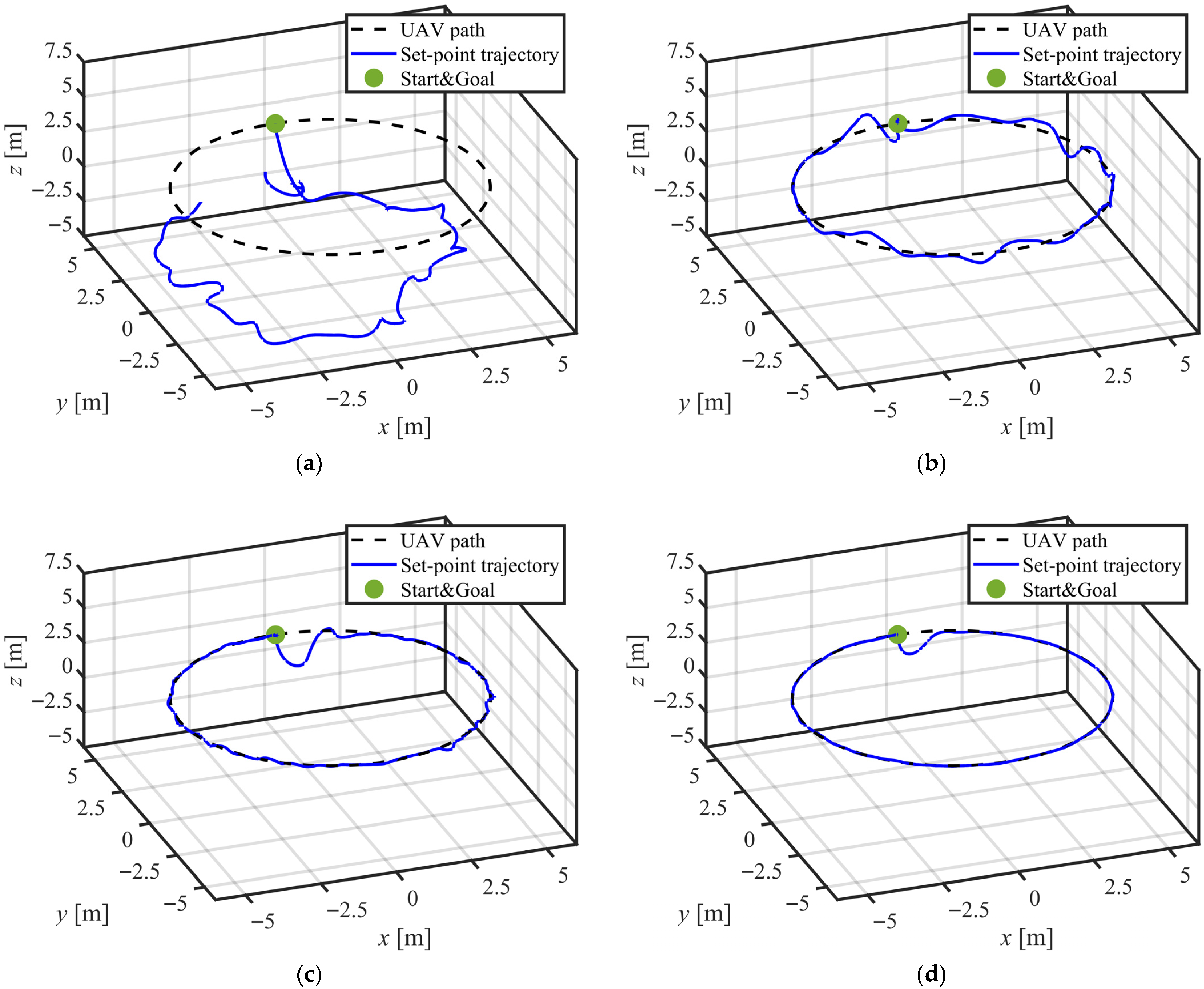
Figure 4a,d show the trajectories of the quadrotor using MPC, MPC+SMDO, MPC+STSMDO, and MPC+ASTSMDO, respectively. The proposed MPC+ASTSMDO method begins tracking the target trajectory the earliest by mitigating control performance degradation due to model errors. It maintains stable flight around the desired trajectory by effectively suppressing wind disturbances. These figures highlight the superior trajectory tracking performance of the proposed method compared to the other approaches.
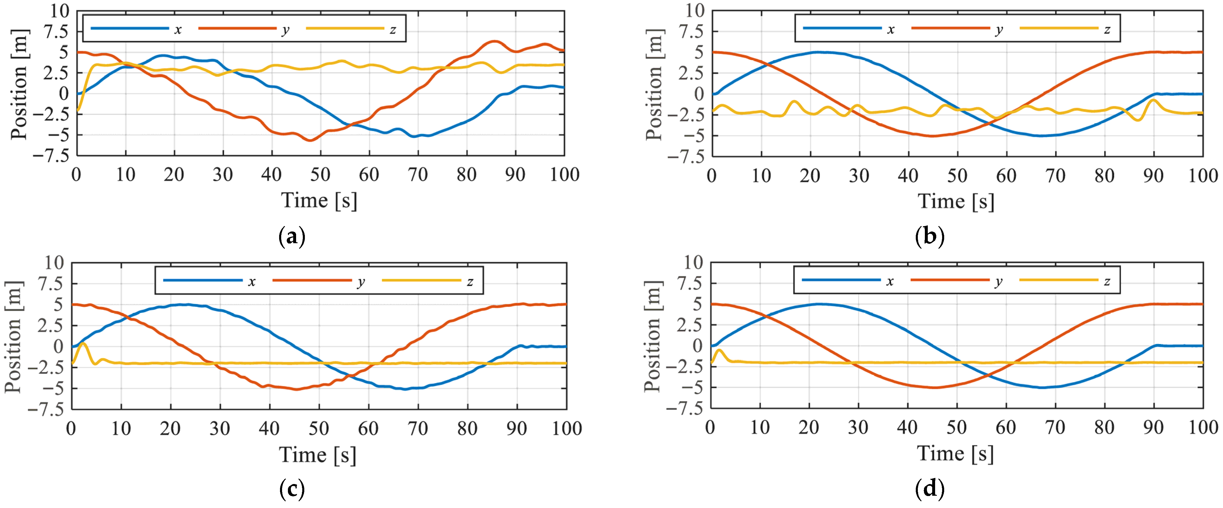
Figure 5a,d depict the time histories of the quadrotor’s position under the four different control schemes. The proposed method effectively suppresses variations in state variables caused by mass mismatches and wind disturbances.
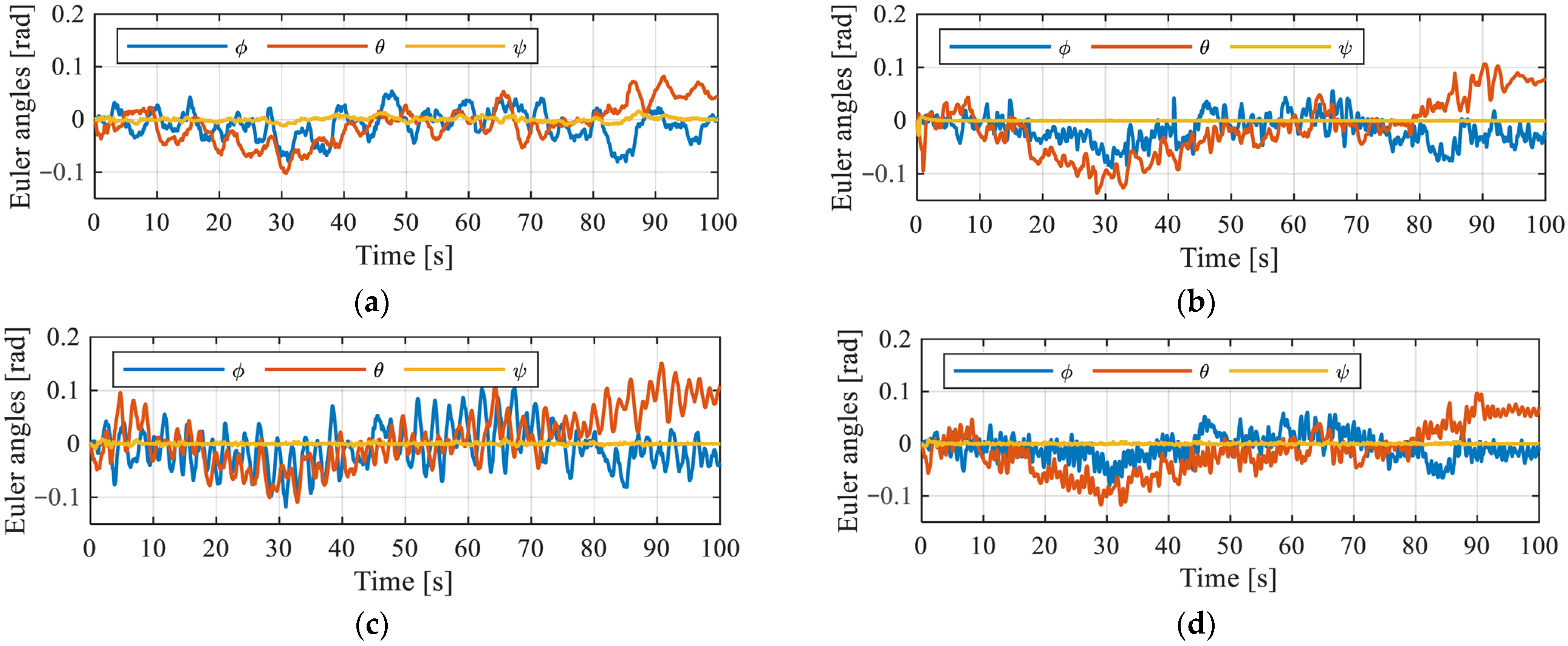
Figure 6a,d show the time histories of the quadrotor’s attitude. The proposed method demonstrates relatively agile adjustments to counter translational wind disturbances while maintaining smaller fluctuations compared to the other methods.
Figure 7a,d illustrate the time histories of the quadrotor’s thrust. Compared to MPC alone, the observer-integrated methods exhibit greater thrust fluctuations as a means of disturbance rejection. The MPC+SMDO method shows large initial fluctuations, which are not observed in the methods utilizing the super-twisting algorithm.
Figure 8a–h present the time histories of translational and rotational disturbances applied to the quadrotor and the corresponding estimated disturbance values obtained using MPC, MPC+SMDO, MPC+STSMDO, and MPC+ASTSMDO. The proposed ASTSMDO approach achieves the highest estimation accuracy. However, it is important to note that SMDO and STSMDO do not exhibit poor estimation accuracy across all six degrees of freedom. While their performance varies by direction, the proposed method consistently achieves high accuracy across all axes, which can be attributed to the effectiveness of the adaptive law.
Figure 9a,b show the adaptive gains of ASTSMDO in the translational and rotational directions, respectively. Distinct differences in adaptive gains are observed between these two motion types. In particular, the adaptive gain for the roll angle is set relatively high to ensure the switching function remains within a predefined threshold. The low estimation accuracy for roll disturbances observed in MPC+STSMDO (Figure 8f) suggests that the adaptive law in the proposed method successfully adjusted the gain to the appropriate level for accurate disturbance estimation.

5. Conclusions

We propose a new control method for quadrotors with excellent trajectory tracking performance under the disturbed condition. MPC and Adaptive STSMDO are combined to improve the robustness against matched bounded disturbance with the unknown boundary and modeling error. The numerical results showed the validity of the proposed method. In future work, we plan to enhance the robustness of the proposed method against unmatched disturbances such as significant time delays and sensor noise. We also plan to apply the designed controller to an actual system and evaluate its performance while taking computational cost into account.

Author Contributions

Methodology, S.K.; Investigation, K.M.; Supervision, K.U. All authors have read and agreed to the published version of the manuscript.

Funding

This work was partly supported by JSPS KAKENHI Grant Number 25K07670.

Data Availability Statement

The original contributions presented in this study are included in the article. Further inquiries can be directed to the corresponding author.

Conflicts of Interest

The authors declare no conflict of interest.

References

  1. Shakhatreh, H.; Sawalmeh, A.; Al-Fuqaha, A.; Dou, Z.; Almaita, E.; Khalil, I.; Othman, N.S.; Khreishah, A.; Guizani, M. Unmanned Aerial Vehicles (UAVs): A Survey on Civil Applications and Key Research Challenges. IEEE Access 2019, 7, 48572–48634. [Google Scholar] [CrossRef]
  2. Elbasueny, B.; El-Sebah, M.I.A.; Shaaban, S. Dynamic Modelling and Control of Quadrotor’s Attitude around Its Hover Position. In Proceedings of the 2019 6th International Conference on Advanced Control Circuits and Systems (ACCS) & 2019 5th International Conference on New Paradigms in Electronics & Information Technology (PEIT), Hurgada, Egypt, 25–28 October 2019; pp. 247–252. [Google Scholar] [CrossRef]
  3. Qiu, X.; Liao, S.; Yang, D.; Li, Y.; Wang, S. Visual geo-localization and attitude estimation using satellite imagery and topographical elevation for unmanned aerial vehicles. Eng. Appl. Artif. Intell. 2025, 153, 110759. [Google Scholar] [CrossRef]
  4. Zhou, S.; He, Z.; Chen, X.; Chang, W. An Anomaly Detection Method for UAV Based on Wavelet Decomposition and Stacked Denoising Autoencoder. Aerospace 2024, 11, 393. [Google Scholar] [CrossRef]
  5. Bolandi, H.; Rezaei, M.; Mohsenipour, R.; Nemati, H.; Smailzadeh, S. Attitude Control of a Quadrotor with Optimized PID Controller. Intell. Control Autom. 2013, 4, 335–342. [Google Scholar] [CrossRef]
  6. Liu, C.; Pan, J.; Chang, Y. PID and LQR Trajectory Tracking Control for an Unmanned Quadrotor Helicopter: Experimental Studies. In Proceedings of the 35th Chinese Control Conference (CCC), Chengdu, China, 27–29 July 2016; pp. 10845–10850. [Google Scholar] [CrossRef]
  7. Saibi, A.; Boushaki, R.; Belaidi, H. Backstepping Control of Drone. Eng. Proc. 2022, 14, 4. [Google Scholar] [CrossRef]
  8. Roy, R.; Islam, M.; Sadman, N.; Mahmud, M.A.P.; Gupta, K.D.; Ahsan, M.M. A Review on Comparative Remarks, Performance Evaluation and Improvement Strategies of Quadrotor Controllers. Technologies 2021, 9, 37. [Google Scholar] [CrossRef]
  9. Heng, X.; Cabecinhas, D.; Cunha, R.; Silvestre, C.; Qingsong, X. A Trajectory Tracking LQR Controller for a Quadrotor: Design and Experimental Evaluation. In Proceedings of the IEEE Region 10 Conference (TENCON 2015), Macao, China, 1–4 November 2015; pp. 1–7. [Google Scholar] [CrossRef]
  10. Fortuna, L.; Frasca, M.; Buscarino, A. Optimal and Robust Control: Advanced Topics with MATLAB®; CRC Press: Boca Raton, FL, USA, 2021. [Google Scholar]
  11. Ganga, G.; Dharmana, M.M. MPC Controller for Trajectory Tracking Control of Quadcopter. In Proceedings of the 2017 International Conference on Circuit, Power and Computing Technologies (ICCPCT), Kollam, India, 20–21 April 2017; pp. 1–6. [Google Scholar] [CrossRef]
  12. Cheng, H.; Yang, Y. Model Predictive Control and PID for Path Following of an Unmanned Quadrotor Helicopter. In Proceedings of the 12th IEEE Conference on Industrial Electronics and Applications (ICIEA), Siem Reap, Cambodia, 18–20 June 2017; pp. 768–773. [Google Scholar] [CrossRef]
  13. Islam, M.; Idres, M.M. Dynamics and Control of Quadcopter Using Linear Model Predictive Control Approach. IOP Conf. Ser. Mater. Sci. Eng. 2017, 184, 012007. [Google Scholar] [CrossRef]
  14. Maciejowski, J.M. Predictive Control: With Constraints; Prentice Hall: London, UK, 2020. [Google Scholar]
  15. Campo, P.J.; Morari, M. Robust Model Predictive Control. In Proceedings of the 1987 American Control Conference (ACC), Minneapolis, MN, USA, 10–12 June 1987; pp. 1021–1026. [Google Scholar]
  16. Zhou, Z.; Wang, M.; Liang, T. H-Infinity Model Predictive Control of Discrete-Time Constrained Singular Piecewise-Affine Systems with Time Delay. In Proceedings of the 2014 Fourth International Conference on Instrumentation and Measurement, Computer, Communication and Control (IMCCC), Harbin, China, 18–20 September 2014; pp. 447–461. [Google Scholar] [CrossRef]
  17. Thakur, M.B.; Schmid, M. Efficient Uncertainty Mitigation in Automated Vehicles: Combining MPC with Model Reference Adaptive Control. IFAC-PapersOnLine 2023, 56, 259–264. [Google Scholar] [CrossRef]
  18. Bhattacharjee, D.; Subbarao, K. Robust Control Strategy for Quadcopters Using Sliding Mode Control and Model Predictive Control. In Proceedings of the AIAA SciTech Forum, Orlando, FL, USA, 6–10 January 2020. AIAA 2020–2071. [Google Scholar] [CrossRef]
  19. Incremona, G.P.; Ferrara, A.; Magni, L. MPC for Robot Manipulators with Integral Sliding Modes Generation. IEEE/ASME Trans. Mechatron. 2017, 22, 1299–1307. [Google Scholar] [CrossRef]
  20. Utkin, V.I. Sliding Mode Control Design Principles and Applications to Electric Drives. IEEE Trans. Ind. Electron. 1993, 40, 23–36. [Google Scholar] [CrossRef]
  21. Levant, A. Sliding Order and Sliding Accuracy in Sliding Mode Control. Int. J. Control 1993, 58, 1247–1263. [Google Scholar] [CrossRef]
  22. Rajappa, S.; Masone, C.; Bülthoff, H.H.; Stegagno, P. Adaptive Super Twisting Controller for a Quadrotor UAV. In Proceedings of the IEEE International Conference on Robotics and Automation (ICRA), Stockholm, Sweden, 16–21 May 2016; pp. 2971–2977. [Google Scholar] [CrossRef]
  23. El Atwi, H.; Daher, N. A Composite Model Predictive and Super Twisting Sliding Mode Controller for Stable and Robust Trajectory Tracking of Autonomous Ground Vehicles. In Proceedings of the 2021 IEEE 3rd International Multidisciplinary Conference on Engineering Technology, Beirut, Lebanon, 2–3 December 2021; pp. 107–112. [Google Scholar] [CrossRef]
  24. Alazki, H.; Escobar, A.G.; Valenzuela, J.E.; Garcia, O. Embedded Super Twisting Control for the Attitude of a Quadrotor. IEEE Lat. Am. Trans. 2016, 14, 3974–3979. [Google Scholar] [CrossRef]
  25. Shtessel, Y.B.; Moreno, J.A.; Plestan, F.; Fridman, L.M.; Poznyak, A.S. Super-Twisting Adaptive Sliding Mode Control: A Lyapunov Design. In Proceedings of the 49th IEEE Conference on Decision and Control (CDC), Atlanta, GA, USA, 15–17 December 2010; pp. 5109–5113. [Google Scholar] [CrossRef]
  26. Nurettin, A.; İnanç, N. High-Performance Induction Motor Speed Control Using a Robust Hybrid Controller with a Super twisting Sliding Mode Load Disturbance Observer. IEEE Trans. Ind. Electron. 2023, 70, 7743–7752. [Google Scholar] [CrossRef]
  27. Liu, Y.-C.; Laghrouche, S.; Depernet, D.; Djerdir, A.; Cirrincione, M. Disturbance-Observer-Based Complementary Sliding-Mode Speed Control for PMSM Drives: A Super-Twisting Sliding-Mode Observer-Based Approach. IEEE J. Emerg. Sel. Top. Power Electron. 2021, 9, 5416–5428. [Google Scholar] [CrossRef]
  28. Anwar, J.; Malik, F.M.; Abdullah, M.; Abbas, A. High Gain and Super-Twisting Sliding Mode Observers for the Adaptive Control of Quadrotor UAV. In Proceedings of the 13th International Bhurban Conference on Applied Sciences and Technology (IBCAST), Islamabad, Pakistan, 12–16 January 2016; pp. 145–153. [Google Scholar] [CrossRef]
  29. Yin, S.; Yang, H.; Kaynak, O. Sliding Mode Observer-Based FTC for Markovian Jump Systems with Actuator and Sensor Faults. IEEE Trans. Autom. Control 2017, 62, 3551–3558. [Google Scholar] [CrossRef]
  30. Zhu, Y.; Qiao, J.; Guo, L. Adaptive Sliding Mode Disturbance Observer-Based Composite Control with Prescribed Performance of Space Manipulators for Target Capturing. IEEE Trans. Ind. Electron. 2019, 66, 1973–1983. [Google Scholar] [CrossRef]
  31. Guo, Z.; Xue, S.; Tan, J.; Li, H.; Yan, D.; Cao, H. Neural Observer-Based Fixed-Time Formation Control of Multiagent Systems. Neurocomputing 2025, 620, 129263. [Google Scholar] [CrossRef]
  32. Al-Hiddabi, S.A. Quadrotor Control Using Feedback Linearization with Dynamic Extension. In Proceedings of the 6th International Symposium on Mechatronics and Its Applications (ISMA), Sharjah, United Arab Emirates, 23–26 March 2009; pp. 1–3. [Google Scholar] [CrossRef]
  33. Hu, Q.; Fei, Q.; Wu, Q.; Geng, Q. Flight Control Design for UAV Using Hierarchical Dynamic Inversion. In Proceedings of the International Conference on Automatic Control and Artificial Intelligence, (ACAI 2012), Xiamen, China, 10–12 March 2012; pp. 1069–1072. [Google Scholar] [CrossRef]
  34. Komiyama, S.; Uchiyama, K.; Masuda, K. Robust Controller Design for Quadrotor Using Model Predictive Control and Adaptive Super Twisting Sliding Mode Control. In Proceedings of the 2024 10th International Conference on Control, Decision and Information Technologies (CoDIT), Valletta, Malta, 22–25 April 2024; pp. 1607–1612. [Google Scholar] [CrossRef]
  35. U.S. Department of Defense. Flying Qualities of Piloted Airplanes; U.S. Military Specification MIL-F-8785C; U.S. Department of Defense: Washington, DC, USA, 1980. [Google Scholar]
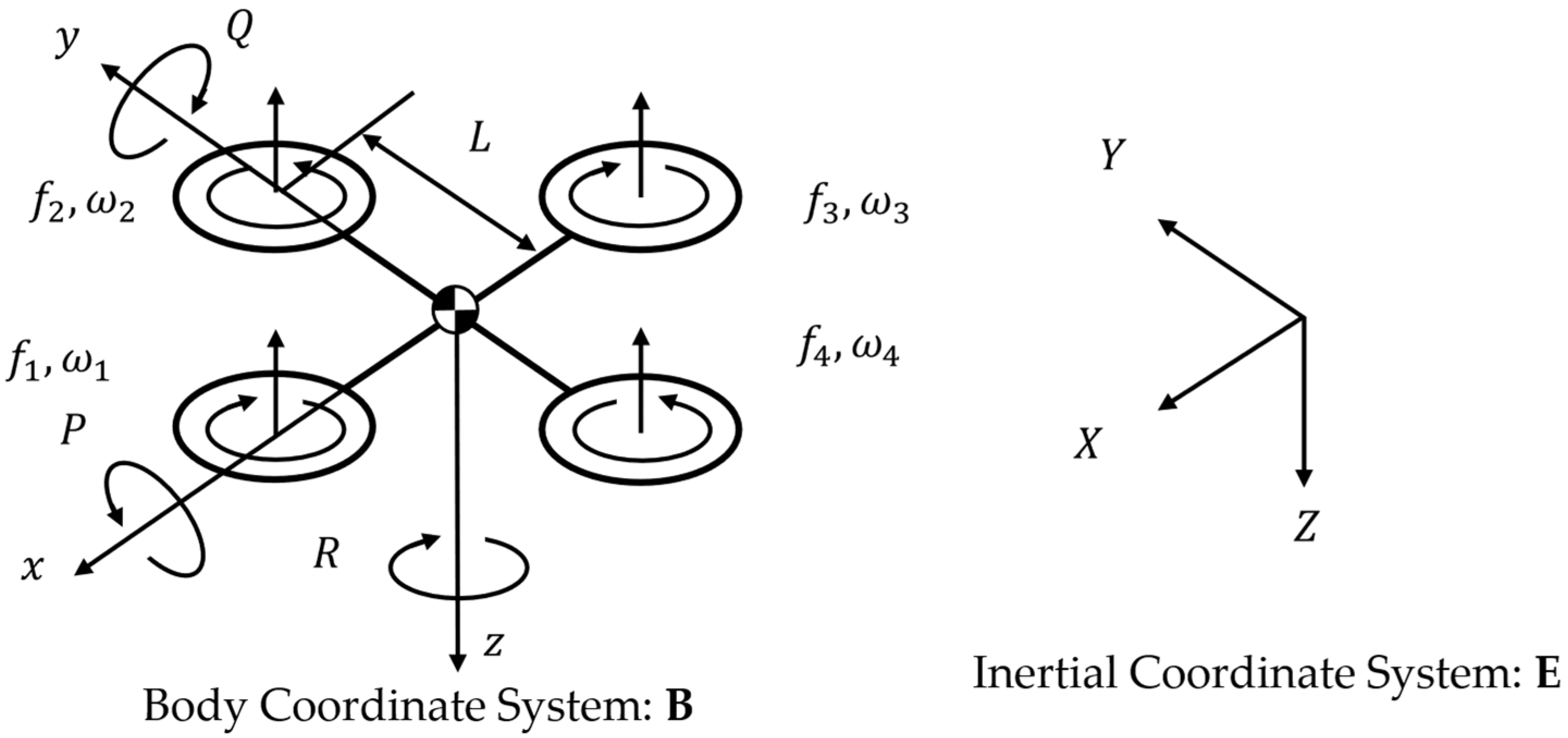
Figure 1. Coordinate system of the Quadrotor UAV.
Drones 09 00576 g001
Figure 2. Block diagram of proposed flight control system for quadrotor UAV.
Drones 09 00576 g002
Figure 3. Block diagram of the proposed control method.
Drones 09 00576 g003
Figure 4. Numerical results of the trajectory of the quadrotor. (a) MPC. (b) MPC+SMDO. (c) MPC+STSMDO. (d) MPC+ASTSMDO.
Drones 09 00576 g004
Figure 5. Numerical results of position. (a) MPC. (b) MPC+SMDO. (c) MPC+STSMDO. (d) MPC+ASTSMDO.
Drones 09 00576 g005
Figure 6. Numerical results of Euler angles. (a) MPC. (b) MPC+SMDO. (c) MPC+STSMDO. (d) MPC+ASTSMDO.
Drones 09 00576 g006
Figure 7. Numerical results of thrust. (a) MPC. (b) MPC+SMDO. (c) MPC+STSMDO. (d) MPC+ASTSMDO.
Drones 09 00576 g007
Figure 8. Numerical results of external disturbance D t , D r and disturbance estimates D ^ t , D ^ r . (a) MPC (translational motion). (b) MPC (rotational motion). (c) MPC+SMDO (translational motion). (d) MPC+SMDO (rotational motion). (e) MPC+STSMDO (translational motion). (f) MPC+STSMDO (rotational motion). (g) MPC+ASTSMDO (translational motion). (h) MPC+ASTSMDO (rotational motion).
Drones 09 00576 g008aDrones 09 00576 g008b
Figure 9. Numerical results of adaptive gains of MPC+ASTSMDO. (a) Translational motion. (b) Rotational motion.
Drones 09 00576 g009
Table 1. Parameters of quadrotor.
Mass m q   [ k g ] 5.0
Variation in mass m q   [ k g ] 2.0
Rotor and axis distance L   [ m ] 0.5
Inertia tensor J   [ k g m 2 ] d i a g ( 0.3125 , 0.3125 , 0.6250 )
Air drag coefficient k d   [ ] 0.25
Lift coefficient of rotor b   [ ] 3.0 × 10 6
Drag coefficient of rotor d   [ ] 1.0 × 10 7
Time constant T c   [ s ] 0.01
Table 2. Parameters of controller and observer.
TranslationRotation
Time constant T r e f 1.5 0.1
Predictive horizon H p 150 10
Control horizon H u 30 3
Window parameter H w 1 1
Weighting matrix Q I 450 × 450 10 4 × I 30 × 30
Weighting matrix R 10 3 × I 90 × 90 I 9 × 9
ASTSMO parameter κ 1 5 5
κ 2 5 5
α m 1 1
μ 0.005 0.005
λ 1 1
STSMO parameter α 1 2 2
α 2 2 2
SMO parameter α 1 5 5
S I 3 × 3 I 3 × 3 I 3 × 3 I 3 × 3
Table 3. Performance evaluation of trajectory tracking.
ISEIAE
MPC+ASTSMO3.5425.502
MPC+STSMO10.9811.88
MPC+SMO17.7733.03
MPC2701515.2
Table 4. Performance evaluation of control input.
f 1 f 2 f 3 f 4 E r
MPC+ASTSMO17421708173317306913
MPC+STSMO17511700174217246917
MPC+SMO17841689176217126947
MPC17271723172917466925
Disclaimer/Publisher’s Note: The statements, opinions and data contained in all publications are solely those of the individual author(s) and contributor(s) and not of MDPI and/or the editor(s). MDPI and/or the editor(s) disclaim responsibility for any injury to people or property resulting from any ideas, methods, instructions or products referred to in the content.