Article

Immersion and Invariance Adaptive Control for Unmanned Helicopter Under Maneuvering Flight

1
National Key Laboratory of the Helicopter Aeromechanics, Nanjing University of Aeronautics and Astronautics, Nanjing 210016, China
2
Unmanned Aerial Vehicle Research Institute, Huaiyin Institute of Technology, Huaian 223003, China
*
Authors to whom correspondence should be addressed.
Drones 2025, 9(8), 565; https://doi.org/10.3390/drones9080565
Submission received: 19 June 2025 / Revised: 22 July 2025 / Accepted: 8 August 2025 / Published: 12 August 2025

Abstract

Highlights

What are the main findings?
  • A low-dimensional immersive system design approach is employed with the I&I (immersion and invariance) theory.
  • To meet the requirements of I&I theory for asymptotic stability points in the system, in the constructed equivalent system, the first two state variables of the error system are artificially set with positive definite conditions to ensure stability.
What is the implication of the main finding?
  • The non-cascade controller is constructed, which solely utilizes the velocity value as feedback.
  • The control performance of the control law is influenced by the equivalent system as well as three parameters in its construction. However, the impact of these three parameters on the control effectiveness is positively correlated and mutually independent, resulting in very low difficulty in parameter tuning.

Abstract

An asymptotic stability velocity tracking controller is designed to enable the autonomous maneuvering flight of unmanned helicopters. Firstly, taking the UH-60A without pilots as the research object, a high-efficient rotor aerodynamic modeling is developed, which incorporates a free-wake vortex method with the flap response of blades. The consummate flight dynamic model is complemented by wind tunnel-validated fuselage/tail rotor load regressions. Secondly, a linear state–space equation is derived via the small perturbation linearization method based on the flight dynamic model within the body coordinate system. A decoupled model is formulated based on the linear state–space equation by employing the implicit model approach. Subsequently, a system of ordinary differential equations is constructed, which is related to the deviation between actual velocity and its expected value, along with higher-order derivatives of this discrepancy. The I&I (immersion and invariance) theory is then employed to facilitate the design of a non-cascade control loop. Finally, the response of desired velocity in longitudinal channel is simulated with step signal to compare the control effect with a PID (proportional–integral–derivative) controller. By adjusting the coefficients, the response progress of the PID controller is similar to the effect of adaptive controller with I&I theory. However, there is no obvious overshoot in the process with I&I adaptive controller, and the average response amplitude accounts for 16.69% of the random white noise, which is 7.38% of the oscillation level under the PID controller. The parameter tuning complexity when employing I&I theory is significantly lower than that of the PID controller, which is evaluated by mathematical derivations and simulations. Meanwhile, the sidestep and pirouette maneuvers are simulated and analyzed to examine the controller in accordance with the performance criteria outlined in the ADS-33E-REF standards. The simulation results demonstrate that the speed expectation-oriented asymptotic stability control can achieve a fast response. Both sidestep and pirouette maneuvers can satisfy the desired performance requirements stipulated by ADS-33E-REF.

1. Introduction

The rotorcraft is not reliant on landing fields and excels in navigating complex, unpredictable environments. Whether fostering low-altitude economic development in urban areas [1], exploring extraterrestrial planetary surfaces [2], or conducting missions in challenging military scenarios [3,4], the unmanned helicopter stands as the ideal choice. These diverse applications underscore a critical need for autonomous flight control systems capable of handling dynamic situations. In each of these domains, the common challenges that such systems face include uncertainty obstacles, unpredictable interference, and real-time decision making under uncertainty. These challenges highlight the necessity for cutting-edge technological innovations that enhance autonomy, adaptability, and decision-making capabilities in rotorcraft systems [5,6].
In recent years, theories and technologies related to unmanned helicopter flight control have been steadily progressing. Notable among these are adaptive control methods, PID control-derived technologies, and fuzzy control techniques, all of which represent advanced innovations in the field. Yan [7] proposed an adaptive tracking flight control scheme tailored for unmanned helicopters to address external disturbances. This approach employs a radial basis function (RBF) network model in conjunction with adaptive methods to effectively handle bounded, unknown external interference. Chen [8] introduced a novel control strategy integrating simple adaptive control (SAC) and quantum logic for quad-rotor helicopters. In cases of external disturbances, this approach demonstrates the capability to reconfigure the control system effectively while maintaining stable helicopter flight. Chen [9] developed an adaptive neuro-based fault-tolerant control scheme for a three-degree-of-freedom (3-DOF) model helicopter that can counteract system uncertainties and unknown external interference. Active disturbance rejection control (ADRC) is an enhanced version of the traditional PID control algorithm, which overcomes the limitations of the PID controller and provides a new control design paradigm [10,11]. Ren [12] proposed a helicopter high-precision trajectory tracking control method based on ant colony optimization–slime mold algorithm (ACO-SMA). By optimizing controller parameters through ACO-SMA, the approach aims to enhance trajectory tracking precision and disturbance rejection capabilities. Compared to traditional PID and ADRC methods, the optimized ADRC demonstrates significant advantages in trajectory tracking accuracy and effectively mitigates the impact of external disturbances, such as turbulence, on helicopter flight. Fuzzy control is an advanced intelligent control method that draws upon fuzzy set theory, fuzzy language variables, and fuzzy logic inference [13,14]. This approach emulates the human decision-making process by handling uncertainties and imprecise information effectively, which specifically include input–output fuzzy subsets, membership function selection, fuzzy rule generation, and fuzzy inference [15]. Ma [16] utilized a fuzzy logic system to estimate system uncertainties. Nonlinear disturbance observers were employed to handle external disturbances and estimation errors from the fuzzy logic system. Simulations demonstrated the effectiveness of the proposed control scheme under conditions of system uncertainty, flight boundary constraints, and external disturbances. Zhang [17] proposed a new asymptotic robust trajectory tracking control method. A general stability analysis framework was presented to prove that the equilibrium point of the overall controller–observer system is asymptotically stable.
ADS-33E-PRF [18] provides detailed quality requirements for both flight and ground handling, encompassing 23 typical maneuver categories. Ferguson [19] evaluated the maneuverability of a composite helicopter by incorporating takeoff–dive and acceleration–deceleration maneuvers. Two specific maneuvers (sidestep and pirouette) are selected to design control laws for autonomous maneuver flight. Performance is assessed based on ADS-33E-REF [18] criteria. Considering that the control performance of the ADRC heavily depends on parameters and requires significant tuning efforts [20,21], as well as the fact that fuzzy control’s effectiveness is highly sensitive to fuzzy rules and higher-order rules are difficult to construct based on experience [22,23], an adaptive control approach has been adopted in this paper for designing the control laws of autonomous maneuver flight for helicopters. Astolfi [24] proposed a new control design method based on immersion and invariance theory (I&I) for asymptotic stabilization and adaptive control of nonlinear systems. This method does not rely on control Lyapunov functions but instead achieves system stabilization by designing target dynamic systems and mappings. Zhao [25] employed I&I adaptive control in the attitude loop to address parameter uncertainties and external disturbances in quad-rotor drones. In the conventional cascaded control architecture of the system, the desired attitude angle was explicitly derived from the desired velocity, while an I&I adaptive controller was implemented in the inner loop to achieve tracking control. The controller structure did not remove the cascade architecture. Zou [26] utilized I&I adaptive control to handle trajectory tracking issues of quad-rotor drones with uncertain inertia parameters, validating the approach through numerical simulations. The actual controller did not rely on the I&I algorithm. A high-precision model of the main rotor system is developed using the free-wake method, while aerodynamic models for other components are constructed based on experimental data. This effort results in the establishment of a highly accurate flight dynamics model for the UH-60A helicopter. Subsequently, the small disturbance linearization technique is employed to derive the linear state–space equations describing the helicopter’s behavior. The I&I adaptive control method is adopted to design reduced-order immersion systems for helicopter flight dynamics models, directly constructing a non-cascade loop controller for flight speed and heading angle. The modeling of the helicopter’s aerodynamics is based on the application of rotor-free-wake methods [27,28] and numerical fitting of other aerodynamic components.

2. Modeling Method

2.1. Flight Dynamics Modeling of a UH-60A Helicopter

The UH-60A is a typical-configuration helicopter with a single main rotor and tail rotor, which has the characteristics of strong coupling and underactuation. Although the UH-60A is a manned helicopter, unmanned operation is selected as the research object. The free-wake method is employed to model the main rotor of UH-60A. By simulating the evolution of the tip vortex, the forces and torques of main rotor under various flight control inputs and state variables are obtained. The accuracy of this method in solving aerodynamic loads has been validated in previous studies [29].
With reference to the aerodynamic load formulas of the fuselage, tail rotor, and horizontal and vertical tails derived from wind tunnel experimental data [30], the aerodynamic loads of each component are integrated within the fuselage coordinate system, as in the following Equation (1):
F x = m d u d t + w q v r + m g sin θ F y = m d v d t + u r w p m g cos θ sin γ F z = m d w d t + v p u x q m g cos θ cos γ M x = I x d p d t + I z I y q r I x z p q + d r d t M y = I y d q d t + I x I z p r + I x z p 2 r 2 M z = I z d r d t + I y I x p q I x z d p d t q r
where F x , F y , F z , M x , M y , and M z denote the summation of aerodynamic forces and torques from all components, u, v, w, p, q, and r represent the velocity and angular acceleration along three orthogonal axes, ϕ and γ correspond to the pitch angle and roll angle of fuselage, respectively, and I x , I y , I z , I x y , I x z , and I y z signify the rotational inertia and product of inertia within the fuselage coordinate system. m stands for the mass of the helicopter and g represents the gravitational acceleration. Based on these equations, the coordination equations between the attitude and angular velocity of the helicopter are derived, thus forming a comprehensive helicopter flight dynamic model, as follows:
d γ d t = p + r cos γ + q sin γ tan θ d θ d t = q cos γ r sin γ d ψ d t = r cos γ + q sin γ cos θ
where ψ represents the yaw angle.
The control inputs U c = δ c , δ e , δ a , δ p T represent the collective pitch, longitudinal cyclic pitch, lateral cyclic pitch, and collective pitch of tail rotor, respectively.
Then, the flight model of the entire helicopter can be expressed in the following form:
X ˙ = f X , U c , t
where t denotes time and X = u , v , w , p , q , r , γ , θ , ψ T .
In the design of flight control laws, the small perturbation linearization method is frequently utilized to decompose helicopter motion into the steady state and disturbance components attributed to the significant nonlinear behavior of helicopters. Equation (3) undergoes a Taylor expansion during the steady motion, with higher-order terms of the second degree and above being neglected, resulting in the following first-order equation form:
Δ x ˙ i = j = 1 9 f i x j 0 Δ x j + k = 1 4 f i δ k 0 Δ δ k + x d
where f i / x j denotes the aerodynamic derivative between the state variables, f i / δ k corresponds to the control derivative of the control inputs to the state variables, and x d represents the error.
After the convergence of the baseline motion state calculation using the free-wake method, and replacing the partial derivative terms with difference terms to calculate the influence gains, the state–space equation can be written in the following form:
Δ X ˙ = A Δ X + B Δ U c + x d
where A represents the state matrix and B denotes the manipulation matrix. x d encompasses the following three primary sources of error: (1) higher-order terms neglected during linearization (which may be mitigated via affine nonlinear modeling approaches), (2) inaccuracies stemming from physical assumptions or incomplete theoretical understanding during the modeling process, and (3) unmeasurable environmental disturbances and sensor noise during actual flight operations. The elements within these matrices vary with the state of baseline motion. The term ‘ Δ ’ is omitted in the following context.

2.2. Implicit Model

Helicopters exhibit two forms of coupling, namely state coupling and control coupling, which significantly increase the control difficulty of helicopters. The strategy of implicit model decoupling control is adopted, which suppresses control coupling through feedforward compensation and reduces state coupling through state feedback. The specific implementation method of the control structure is shown in Figure 1.
The original state–space equations are transformed into the following equation:
x = A d x + B d x c
where H represents the feedforward matrix, K denotes the state feedback matrix, and x c stands for the decoupled virtual control input. After decoupling, the state matrix A d and the control matrix, B d satisfy the following form:
A d = A B K B d = B H
Assuming that the expected responses of each channel are first-order transfer functions of the implicit model after decoupling, the responses of the four state variables, namely vertical velocity, roll rate, pitch rate, and yaw rate, satisfy the following first-order form of the hidden model:
x / x c = ω x / s + ω x
Within this framework, the implicit model explicitly assigns each expected frequency ( ω x ) to its corresponding channel during system construction. Moreover, the design of the implicit model inherently decouples state variables related to the attitude from other channels, thereby enabling independent velocity control across different transmission pathways. Equation (9) is as follows:
u ˙ = A u u ˙ u + A θ u ˙ θ v ˙ = A v v ˙ v + A ϕ v ˙ ϕ
where parameters ( A u u ˙ , A θ u ˙ , A v v ˙ , A ϕ v ˙ ) correspond to cross-coupling coefficients governing state-variable interactions in the primitive system matrix. Through rigorous decoupling procedures, we derive the transformed state–space representation with a block-diagonal structure and its associated control matrix, which take the following canonical form:
A d = A u u ˙ 0 0 0 0 0 0 A θ u ˙ 0 0 A v v ˙ 0 0 0 0 A ϕ v ˙ 0 0 0 0 ω w 0 0 0 0 0 0 0 0 0 ω p 0 0 0 0 0 0 0 0 0 ω q 0 0 0 0 0 0 0 0 0 ω r 0 0 0 0 0 0 1 0 0 0 0 0 0 0 0 0 1 0 0 0 0 0 0 0 0 0 1 0 0 0 , B d = 0 0 0 0 0 0 0 0 ω w 0 0 0 0 ω p 0 0 0 0 ω q 0 0 0 0 ω r 0 0 0 0 0 0 0 0 0 0 0 0
Thus, Equation (11) is as follows:
K = B 1 A A d H = B 1 B d
Due to the underactuated configuration of the helicopter, B cannot be directly inverted. This structural constraint necessitates the implementation of the Moore–Penrose pseudoinverse ( B = B T B 1 B T ) for pseudoinverse control allocation. The deviation value formed after being brought into original system is regarded as the disturbance compared to the nominal model.

3. Adaptive Controller Design Taking Advantage of Immersion and Invariance Theory

3.1. The Immersion and Invariance Theory

Consider the following system:
x ˙ = f x + g x u
where the state variables x R n and input vector u R m satisfy the dimensional condition n > m .
The problem of stabilization involves determining a state feedback control law u = v x , which renders the closed-loop system asymptotically stable at its equilibrium point x * R n . Assuming the existence of a specific mapping relationship between the system’s dynamics and the control inputs, this control design seeks to ensure stability through appropriate feedback mechanisms. Let p < n and assume the following mappings:
α : R p R p ;   π : R p R n ;   c : R p R m ; δ : R n R n p ;   Λ , : R n × n p R m ;
such that the following assumptions hold:
(A1) (Target system): There is a lower-dimensions system compared with original system ( ξ ˙ = α ξ , ξ R p ), which has an asymptotically stable equilibrium point ξ * and π ξ * = x * .
(A2) (Immersion condition): For all ξ R p , Equation (13) is as follows:
f π ξ + g π ξ c ξ = π ξ α ξ
(A3) (Implicit manifold): The following set identity holds:
M = x t R n | δ x = 0 = x t R n | x = π ξ , ξ R p
The corresponding mapping π ξ = π 1 ξ , π 2 ξ T is constructed under the assumption that x = x 1 , x 2 T and x 1 R p , x 2 R n p . Then, optionally, if the inverse mapping of π 1 ξ exists, Equation (15) is as follows:
δ x = x 2 π 2 π 1 1 x 1
(A4) (Manifold attractivity and trajectory boundedness): All trajectories of the system are displayed as follows:
z ˙ = δ x f x + g x Λ x , z x ˙ = f x + g x Λ x , z
The trajectories are bounded and satisfy the following Equation (17):
lim t z t = 0
Then, x * is the globally asymptotically stable equilibrium of the closed-loop system, as follows:
x ˙ = f x + g x Λ x , z

3.2. The Design of the Controller

As demonstrated in Section 3.1, the I&I theory is applicable to systems possessing global or local asymptotically stable equilibrium points. However, helicopter systems exhibit unstable modes in certain channels, such as the longitudinal channel’s long-period mode, where flight speed and pitch angle exhibit an unstable and divergent relationship. Consequently, direct application of I&I theory for constructing control laws is not feasible. The following error formulation derived from the decoupling channels presented in Section 2.2 is proposed to transform the original system into one that can be stabilized to the desired velocity:
e ˙ 1 = k e 1 + e 2 e ˙ 2 = l e 2 + e 3
where e 1 denotes the discrepancy between the actual forward speed response u and the target speed u d . Both k and l are positive constants.
After employing the implicit model, the state–space equations concerning longitudinal velocity, pitch angle, and pitch angle velocity are as follows:
u ˙ q ˙ θ ˙ = A u u ˙ 0 A θ u ˙ 0 ω q 0 0 1 0 u q θ + 0 ω q 0 q c
The relationship between e ˙ 3 and e 1 is established by integrating Equation (19), resulting in the following Equation (21):
e ˙ 3 = l e ˙ 2 + e ¨ 2 = e 1 + k + l e ¨ 1 + k l e ˙ 1
Furthermore, Equation (22) is as follows:
e ˙ 3 = C u u + C q q + C θ θ + k l u ˙ d + k + l u ¨ d + u d + A θ u ˙ ω q q c
where Equation (23) is as follows:
C u = A u u ˙ 3 + A u u ˙ 2 k + l + A u u ˙ k l C q = A u u ˙ A θ u ˙ A θ u ˙ ω q + A θ u ˙ k + l C θ = A θ u ˙ k l + A u u ˙ A θ u ˙ k + l + A u u ˙ 2 A θ u ˙
Expressing e ˙ 3 as the transfer relationship among e 1 , e 2 , and e 3 , the original system (Equation (20)) is, thus, transformed into the following state–space equation formulated in terms of error:
e ˙ 1 = k e 1 + e 2 e ˙ 2 = l e 2 + e 3 e ˙ 3 = C 1 e 1 + C 2 e 2 + C 3 e 3 + D 0 u d + D 1 u ˙ d + D 2 u ¨ d + D 3 u d + A θ u ˙ ω q q c
in which Equation (25) is as follows:
C 1 = C u + C q k k + A u u ˙ / A θ u ˙ C θ k + A u u ˙ / A θ u ˙ C 2 = C q A u u ˙ + k + l / A θ u ˙ + C θ / A θ u ˙ C 3 = C q / A θ u ˙ D 0 = C u D 1 = C q A u u ˙ / A θ u ˙ + C θ / A θ u ˙ k l D 2 = C q / A θ u ˙ k + l D 3 = 1
The system fulfills the criteria for the existence of a globally asymptotically stable point, as required by the I&I adaptive control approach. That is, Equation (26) is as follows:
e * = e 1 * , e 2 * , e 3 * T = 0 , 0 , 0 T
The following target system is constructed:
α ξ = k ξ π ξ * = e *
In fact, different construction forms of the target system will form different control laws, affecting the performance of the controller. In order to simplify the controller and improve the computing efficiency, the controller designed here is developed around the linear relationship of errors to compare its performance with that of the PID controller. We fix π 1 ξ = ξ , and the following mapping is derived by combining Equation (13) and System (24):
π 2 ξ = π 3 ξ = 0
Substituting the implicit manifold, i.e., the following Equation (29):
z t = δ e = e 2 , e 3 T = 0 , 0
into Equation (16), we obtain the following Equation (30):
z ˙ = l e 2 + e 3 C 1 e 1 + C 2 e 2 + C 3 e 3 + D 0 u d + D 1 u ˙ d + D 2 u ¨ d + D 3 u d + A θ u ˙ ω q Λ e , z
Let Equation (31) be as follows:
A θ u ˙ ω q Λ e , z = C 1 e 1 + C 2 e 2 + C 3 e 3 + D 0 u d + D 1 u ˙ d + D 2 u ¨ d + D 3 u d h e 3
where h is positive constant, then Equation (32) is as follows:
z ˙ = e ˙ 2 h e 3
When the system is asymptotically stable, subject to lim t z t = 0 , and z ˙ remains bounded, the control law is given by the following Equation (33):
q c = Λ e , z
Figure 2 is the I&I adaptive control structure with velocity as feedback independently of the longitudinal channel.

4. Results

4.1. The Simulation of Step Signals

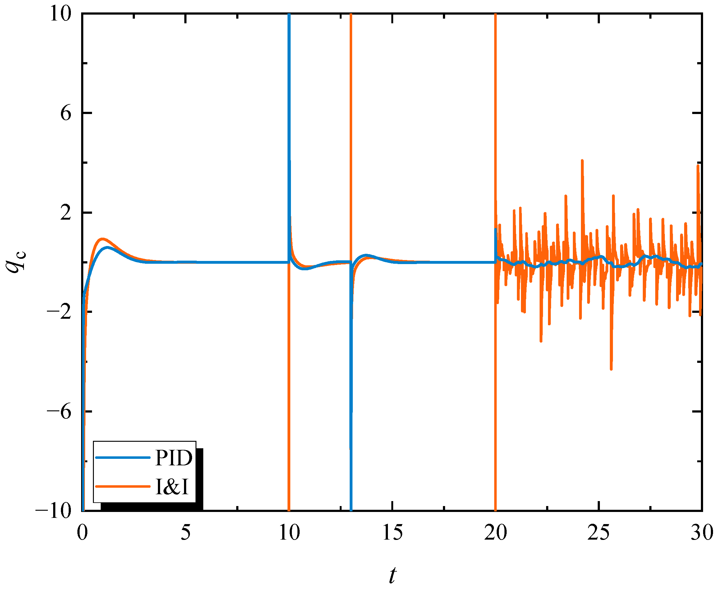
By selecting specific parameters (k = 2, l = 2, and h = 20), the response process of the helicopter under these conditions is presented in Figure 3, showing the transition from hovering to level flight at a speed of 10 knots. The pitch angle and angular rate evolution during this process are shown in Figure 4, while the changes in control inputs are illustrated in Figure 5. Within approximately 3 s, the forward velocity reaches its desired value without significant overshoot, with the attitude angle initially descending before ascending to stabilize at a balance matching the desired forward speed. After the tuning of the PID parameters, the response effect is similar to that of the I&I adaptive controller. However, there is a significant difference between them in terms of disturbance suppression. When a step disturbance is applied to the system at 10 s, the longitudinal velocity exhibits an abrupt change before asymptotically approaching its expected value in approximately 3 s under the influence of the perturbation environment. This adjustment occurs as the adaptive controller modifies the control inputs to balance the attitude angle and angular rate. When the disturbance ceases, the adaptive controller rapidly adjusts to re-follow the desired trajectory without disturbance. Notably, under the same PID parameter settings, significant overshoot is observed during this process. At 20 s, a random white noise disturbance is introduced into the system. The response begins to deviate at the moment of disturbance introduction, unlike the steady-state perturbations previously analyzed. This disturbance is characterized by being completely random and time-varying. Over the duration of the disturbance (10 s), longitudinal velocity asymptotically stabilizes within a few seconds after initial adjustment, maintaining stable flight despite significant changes in the disturbance. The attitude angle and angular rate continuously adapt to maintain balance in this stochastic perturbation environment. While the PID controller does exhibit some ability to suppress random white noise disturbances, it is unable to effectively predict and control responses to fully random future disturbances, resulting in deviations from the desired speed that are significantly larger than those achieved by the I&I adaptive controller. In the process, the average response amplitude under random disturbance accounts for 16.69% of the white noise, which is 7.38% of the PID control process. The fundamental reason lies in the fact that the I&I adaptive controller incorporates a third-order error perturbation into its design, effectively integrating second-order differential signals of the deviation into the control law. In contrast, the PID controller only introduces first-order differential signals based on the desired attitude angle. From the perspective of the energy required for control (as shown in Figure 5), although the I&I adaptive control law achieves better control performance, it requires a higher energy demand. However, in the present study, the controller inputs were subjected to saturation constraints. Without considering the amplitude limitations of control inputs, the I&I adaptive controller would demonstrate even superior disturbance rejection performance than that shown in Figure 5. On the other hand, given the inevitable presence of disturbances in real-world UAV applications, the controller’s ability to suppress disturbances over extended time periods becomes critically important. As illustrated in Figure 3, during the 10 s random noise disturbance test, while both controllers showed inadequate suppression during the initial 2 s transient phase following disturbance onset, the I&I adaptive controller exhibited significantly stronger disturbance rejection capability than the PID controller throughout the subsequent 8 s period.

4.2. Analysis of System Parameters

The flight dynamics model developed solely based on the UH-60’s aerodynamic configuration inherently represents an unstable system. Regarding stability proof, the approach differs from conventional Lyapunov function construction methods. Instead, we rely on the asymptotic stability characteristics of the constructed error system (as theoretically established in Ref. [24]). While this error system is derived from the unstable helicopter dynamics model, the introduction of positive definite coefficients (k, l > 0) guarantees its asymptotic stability properties.
In the I&I adaptive control algorithm, a third-order system was constructed for error tracking, incorporating two positive constants k and l, as well as another positive constant h included in the control law. The selection of these three parameters significantly impacts the system’s tracking performance and control effectiveness.
Substituting control law (33) into the original system (20) and combining it with Laplace transforms, the transfer relationship between the actual longitudinal speed and the desired velocity can be obtained as follows:
u = J 0 Ξ s u d + J 1 Ξ s u ˙ d + J 2 Ξ s u ¨ d + J 3 Ξ s u d
in which Equations (35) and (36) are as follows:
Ξ s = s 3 + 1 X θ u ˙ X u u ˙ ω q X θ u ˙ 1 + k + l + h s 2 + X u u ˙ ω q + k l + h k + l s + k l h
J 0 = C 1 + k C 2 + k l C 3 + h D 0 J 1 = C 2 + k + l C 3 + h D 1 J 2 = C 3 + h D 2 J 3 = D 3
Considering the constant expectation response problem ( u ˙ d = u ¨ d = u d = 0 ), the transfer function is as follows:
G s = u u d = J 0 Ξ s
u u d = C 1 + k C 2 + k l C 3 + h D 0 C 1 + k C 2 + k l C 3 + h = 1 X u u ˙ h X u u ˙ 2 k l h X u u ˙ + k + l
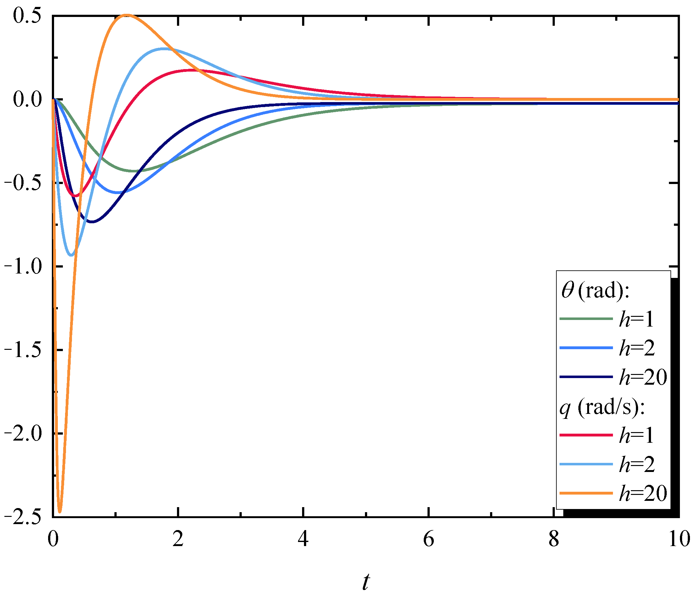
where u is the steady-state response of the system after convergence. There is a stability deviation after the system is stabilized in Equation (38). By appropriately selecting the parameter h, the steady-state tracking error can be minimized. Figure 6 and Figure 7 denote the response process of the system for different values of h (k = 2, l = 2). Specifically, increasing h improves the system’s transient response speed while reducing the steady-state bias. However, beyond a certain value, further increases in h do not significantly enhance the system’s performance. The control law is most sensitive to e 3 due to its dependence on higher-order derivatives of the error, which provides better prediction accuracy for future errors. This increased sensitivity allows the control law to respond more effectively to disturbances without causing excessive oscillations or overshoots in the system response (e.g., pitch angle and angular velocity).
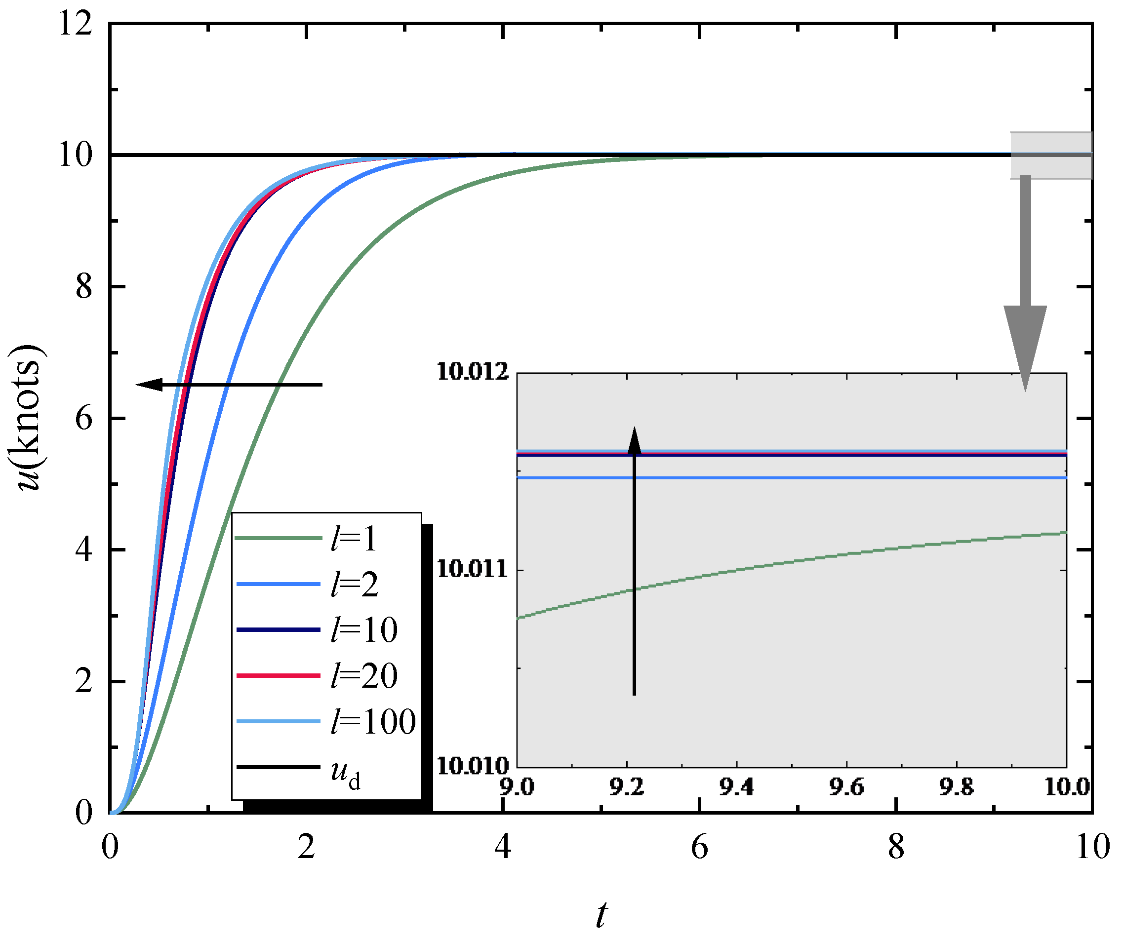
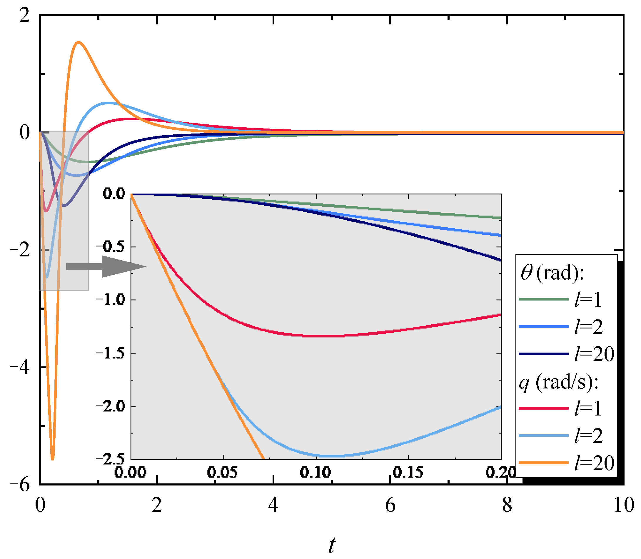
In Equation (35), parameters k and l are in a completely symmetric form. Since the influence of k on the velocity response follows the same pattern as l, the subsequent analysis focuses solely on the single variable l. Figure 8 and Figure 9 illustrate the response processes for different values of l when k = 2 and h = 20. As l increases, the velocity response also increases. However, once l reaches a certain level, it no longer significantly affects the velocity response. The difference between the impact of changing l and changing h is that, in the steady state, an increase in l leads to an increase in the steady-state deviation, although this impact is limited and there is an upper bound. As shown in Figure 9, changes in l affect the duration of control when responding to a step signal. Unlike the impact of changing h, different values of l do not alter the initial rate of change of q.
As can be seen from the above analysis, the selection of the three parameters only alters the response speed of the decoupled system’s longitudinal velocity to the desired velocity and the steady-state deviation within a small range. It does not produce the oscillatory response of an underdamped system and excessive overshoot characteristic. Compared to the PID method, the difficulty of parameter selection is lower.

4.3. Sidestep and Pirouette

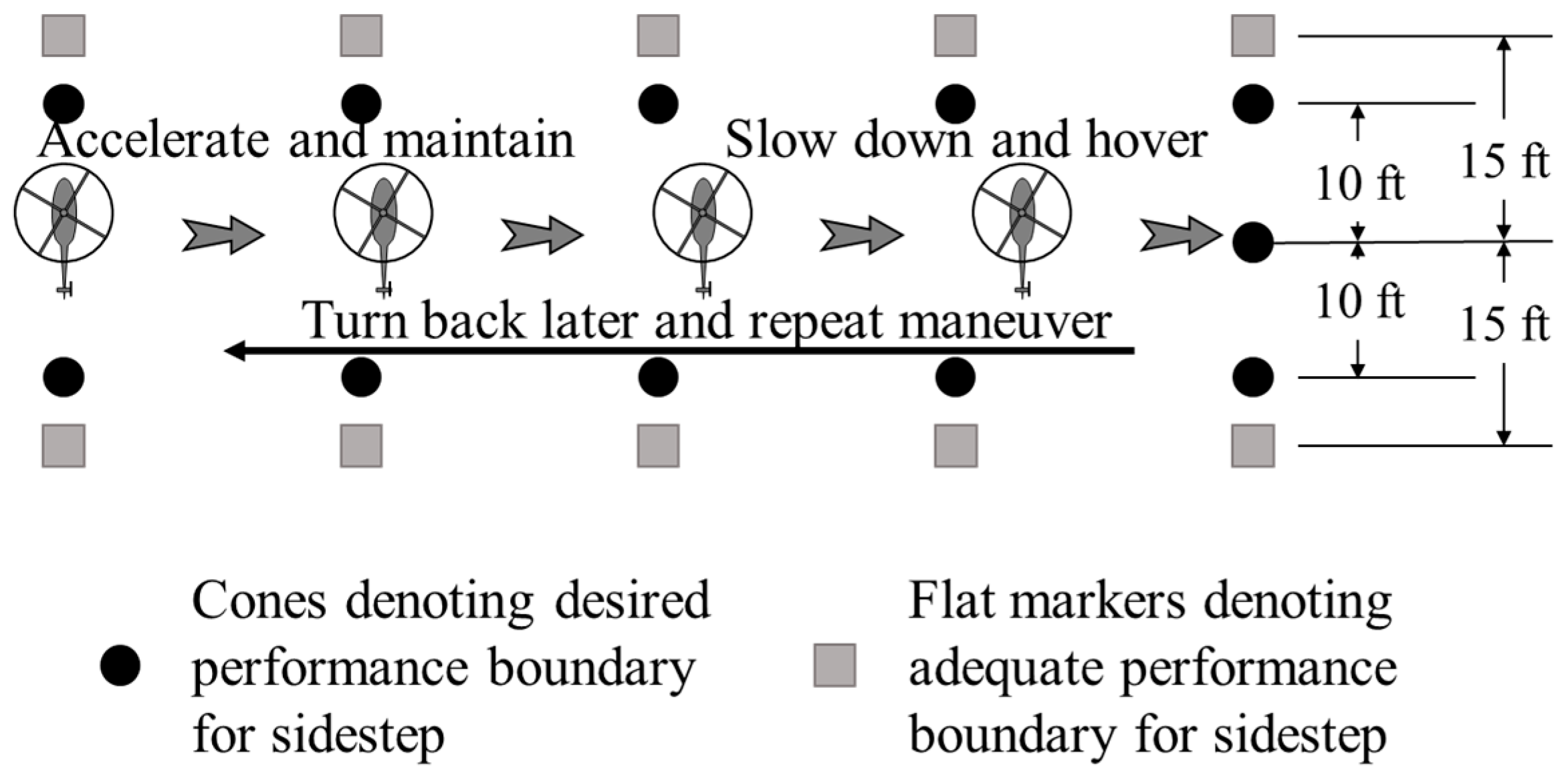
The sidestep maneuver subject stipulated in ADS-33E-REF is a standard flight subject for examining the performance boundary position maneuver capability. This subject focuses on whether the helicopter has any adverse interaxial coupling and the coordination ability between the roll angle and the collective pitch when maintaining altitude, while also demanding the agility of the maneuver action. In this paper, the implicit model method is applied to meet the decoupling requirements, and the I&I adaptive control method is used to achieve the agility requirement of the maneuver subject. Figure 10 shows the sidestep maneuver route recommended in ADS-33E-REF, in which the desired sidestep speed is a step signal in four stages.
Figure 11 illustrates the response processes of lateral velocity, roll angle, and angular velocity during the sidestep maneuver. Within the 0–20 s interval, the helicopter undergoes lateral acceleration, during which the velocity asymptotically stabilizes at the desired speed of 40 knots. The lateral velocity is maintained at 40 knots until deceleration begins at 20 s, gradually stabilizing towards a hover state. Subsequently, a sidestep in the opposite direction commences after 40 s, and deceleration towards the initial position occurs until a hover state is achieved at 60 s. ADS-33E-REF specifies performance criteria for the roll angle deviation that occurs 1.5 s into the acceleration and deceleration phases. Figure 12 provides detailed plots of the roll angle changes from the start to 1.5 s for each of the four acceleration and deceleration segments, all of which meet the specified criteria. Table 1 presents a comparison between the state indicators listed in ADS-33E-REF and the actual response measurements.
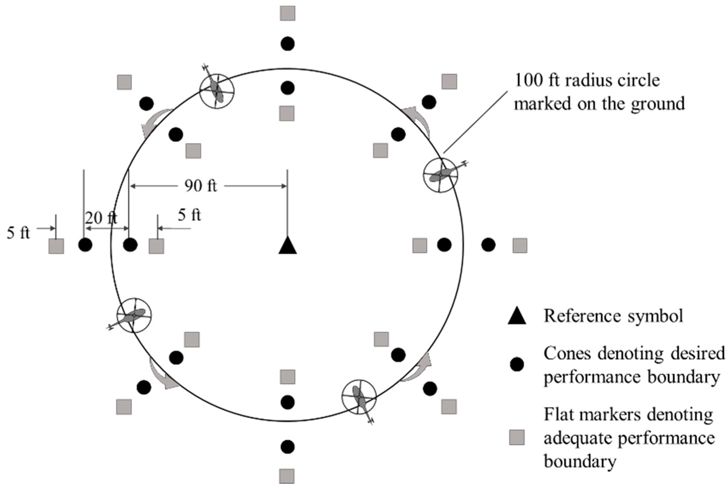
This maneuver performs a simulated low-altitude pirouette while engaging in combat, which primarily evaluates the ability to control pitch, roll, yaw, and vertical movements during hover and low-speed flight. Figure 13 depicts the reference trajectory for pirouette.
Given that the pirouette maneuver imposes specific requirements on the completion time, which distinguishes it from the conventional navigation law design, the following time-varying position expectations ( X d l o c , Y d l o c ) are designed in response to this maneuver:
X d l o c = 100 sin 2 π T t , t < T 0 , t T , Y d l o c = 100 100 cos 2 π T t , t < T 0 , t T
The actual position is denoted by ( X l o c , Y l o c ), and the desired heading angle is represented as follows:
X l o c = 0 t v cos ψ + u sin ψ d τ Y l o c = 0 t v sin ψ + u cos ψ d τ ψ d = arctan X l o c Y l o c 100
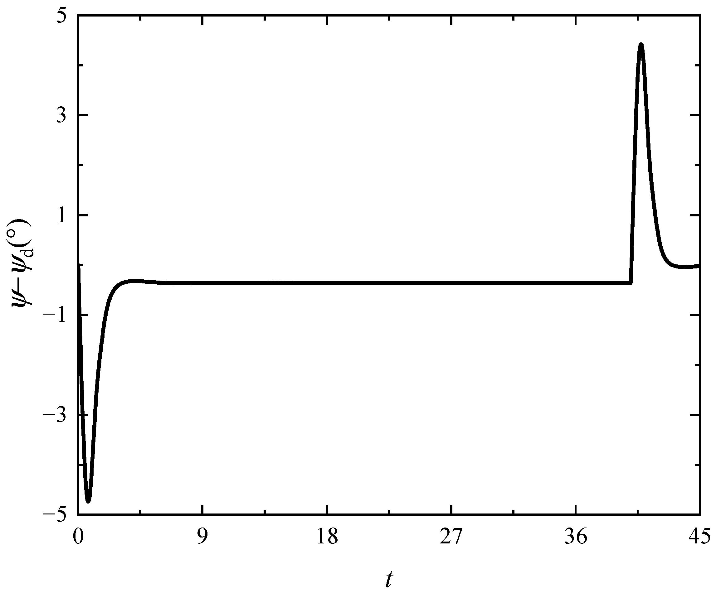
On this foundation, the methodology for constructing control laws is consistent with what was described earlier. In this study, the completion time of the pirouette maneuver is set to 40 s, followed by 5 s additional of hover. The simulation results of position tracking during the maneuver are shown in Figure 14. The origin point marked in the figure represents the initial starting point of the pirouette maneuver. During the first 40 s, the helicopter constructs its desired flight velocity based on the position deviation between its actual and expected positions, successfully performing the pirouette maneuver and returning to the starting point. Immediately after reaching the starting point, the desired flight state transitions to hover. However, due to residual flight inertia, the helicopter continues to travel along the instantaneous velocity direction for 40 s post-completion. Subsequently, as the position continues to evolve, an opposing desired velocity is generated. Within a span of 3 s, corrective maneuvers bring the helicopter back toward the starting point, and a stable hover state is achieved thereafter. Figure 15 illustrates the heading angle deviation relative to the reference point during the pirouette maneuver. In the initial phase of the maneuver, the heading angle exhibits a lagging characteristic due to its dependence on the helicopter’s actual position at any given time, resulting in an initial negative deviation compared to the navigation trajectory. Through the entire flight duration, this inherent lag produces a consistently small negative heading angle deviation. Near the end of the maneuver, inertia at the moment of completion causes a positive deviation in the heading angle; however, within the subsequent 5 s, lateral corrective movements toward the starting point eliminate the deviation, bringing it back to zero. These results demonstrate that, while the helicopter successfully completes the maneuver and corrects position deviations within the prescribed timeframe, there remain persistent small deviations during both the initial and final stages of the motion. Further refinement of the control algorithm is, therefore, necessary to enhance overall flight accuracy.

5. Conclusions

(1) Using the I&I adaptive control methodology, control laws are developed for each helicopter channel. Under similar response characteristics, the disturbance suppression effect of the proposed controller is significantly better than that of the PID controller. In addition, a detailed analysis is conducted to evaluate the impact of unspecified parameters in the error models on system state response effect. Each control parameter has a completely monotonic effect on the control effect.
(2) Different from conventional methods that distinguish between velocity and attitude angle and formulate control laws separately within a loop control framework, a low-dimensional immersive system design approach is employed, and a non-cascade controller is constructed, which solely utilize the velocity value as feedback to construct the system. The simulation analyses demonstrate the controller’s robustness and reliability through comprehensive testing, effectively confirming its operational efficiency and stability in diverse scenarios.
(3) Focused on two representative maneuvers (sidestep and pirouette), control laws and guidance laws are designed through systematic development. Simulations are performed to validate the proposed control strategy, demonstrating that the method satisfies the performance criteria outlined in the ADS-33E-REF standard.

Author Contributions

Conceptualization, X.Z.; methodology, X.Z.; software, X.Z.; validation, Y.X.; formal analysis, Y.X.; resources, Q.Z.; data curation, S.D.; writing—original draft preparation, X.Z.; writing—review and editing, Q.Z.; supervision, Y.X.; funding acquisition, Q.Z. All authors have read and agreed to the published version of the manuscript.

Funding

This research was funded by the National Natural Science Foundation of China (No. 12032012), and the Priority Academic Program Development of Jiangsu Higher Education Institutions, China.

Data Availability Statement

Dataset available on request from the authors. The raw data supporting the conclusions of this article will be made available by Xu Zhou (email address: zhoux@nuaa.edu.cn).

Acknowledgments

Thanks for the technical support from the National Key Laboratory of Helicopter Aeromechanics.

Conflicts of Interest

The authors declare no conflicts of interest.

References

  1. Huang, X. The Small-drone Revolution is Coming—Scientists Need to Ensure it Will be Safe. Nature 2025, 637, 29–30. [Google Scholar] [CrossRef]
  2. Grip, H.F.; Lam, J.N.; Bayard, D.; Conway, D.T.; Singh, G.; Brockers, R.; Delaune, J.; Matthies, L.; Malpica, C.; Brown, T.; et al. Flight Control System for NASA’s Mars Helicopter. In Proceedings of the AIAA Scitech Forum, San Diego, CA, USA, 7–11 January 2019. [Google Scholar] [CrossRef]
  3. Takahashi, M.D.; Fujizawa, B.T.; Lusardi, J.A.; Whalley, M.S.; Goerzen, C.L.; Schulein, G.J.; Mielcarek, N.L.; Cleary, M.J.; Carr IV, J.P. Autonomous Guidance and Flight Control on a Partial-authority Black Hawk Helicopter. J. Aerosp. Inf. Syst. 2021, 18, 686–692. [Google Scholar] [CrossRef]
  4. Takahashi, M.D.; Fujizawa, B.T.; Lusardi, J.A.; Goerzen, C.L.; Cleary, M.J.; Carr IV, J.P.; Waldman, D.W. Comparison of Autonomous Flight Control Performance Between Partial- and Full-Authority Helicopters. J. Guid. Control Dyn. 2022, 45, 885–892. [Google Scholar] [CrossRef]
  5. Santoso, F.; Garratt, M.A.; Anavatti, S.G. State-of-the-Art Intelligent Flight Control Systems in Unmanned Aerial Vehicles. IEEE Trans. Autom. Sci. Eng. 2018, 15, 613–625. [Google Scholar] [CrossRef]
  6. Abdelmaksoud, S.I.; Mailah, M.; Abdallah, A.M. Control Strategies and Novel Techniques for Autonomous Rotorcraft Unmanned Aerial Vehicles: A Review. IEEE Access 2020, 8, 195142–195169. [Google Scholar] [CrossRef]
  7. Yan, K.; Wu, Q. Adaptive Tracking Flight Control for Unmanned Autonomous Helicopter with Full State Constraints and Actuator Faults. ISA Trans. 2022, 128 Pt B, 32–46. [Google Scholar] [CrossRef] [PubMed]
  8. Chen, F.; Wu, Q.; Jiang, B.; Tao, G. A Reconfiguration Scheme for Quadrotor Helicopter via Simple Adaptive Control and Quantum Logic. IEEE Trans. Ind. Electron. 2015, 62, 4328–4339. [Google Scholar] [CrossRef]
  9. Chen, M.; Shi, P.; Lim, C.C. Adaptive Neural Fault-tolerant Control of a 3-DOF Model Helicopter System. IEEE Trans. Syst. Man Cybern. Syst. 2016, 46, 260–269. [Google Scholar] [CrossRef]
  10. Han, J. From PID to Active Disturbance Rejection Control. IEEE Trans. Ind. Electron. 2009, 56, 900–910. [Google Scholar] [CrossRef]
  11. Feng, H.; Guo, B. Active Disturbance Rejection Control: Old and New Results. Annu. Rev. Control 2017, 44, 238–248. [Google Scholar] [CrossRef]
  12. Ren, B.; Du, S.; Cui, Z.; Xu, Y.; Zhao, Q. High-precision Trajectory Tracking Control of Helicopter Based on Ant Colony Optimization-slime Mould Algorithm. Chin. J. Aeronaut. 2025, 38, 103172. [Google Scholar] [CrossRef]
  13. Precup, R.E.; Nguyen, A.T.; Blažič, S. A Survey on Fuzzy Control for Mechatronics Applications. Int. J. Syst. Sci. 2024, 55, 771–813. [Google Scholar] [CrossRef]
  14. Nguyen, A.T.; Taniguchi, T.; Eciolaza, L.; Campos, V.; Palhares, R.; Sugeno, M. Fuzzy Control Systems: Past, Present and Future. IEEE Comput. Intell. Mag. 2019, 14, 56–68. [Google Scholar] [CrossRef]
  15. Hu, Y.; Yang, Y.; Li, S.; Zhou, Y. Fuzzy Controller Design of Micro-unmanned Helicopter Relying on Improved Genetic Optimization Algorithm. Aerosp. Sci. Technol. 2020, 98, 105685. [Google Scholar] [CrossRef]
  16. Ma, H.; Chen, M.; Feng, G.; Wu, Q. Disturbance-Observer-Based Adaptive Fuzzy Tracking Control for Unmanned Autonomous Helicopter with Flight Boundary Constraints. IEEE Trans. Fuzzy Syst. 2023, 31, 184–198. [Google Scholar] [CrossRef]
  17. Zhang, X.; Zhuang, Y.; Zhang, X.; Fang, Y. A Novel Asymptotic Robust Tracking Control Strategy for Rotorcraft UAVs. IEEE Trans. Autom. Sci. Eng. 2023, 20, 2338–2349. [Google Scholar] [CrossRef]
  18. ADS-33E-PRF; Aeronautical Design Standard, Handling Qualities Criteria for Military Rotorcraft. US Army: Washington, DC, USA, 2000.
  19. Ferguson, K.; Thomson, D. Maneuverability Assessment of a Compound Helicopter Configuration. J. Am. Helicopter Soc. 2016, 61, 012008. [Google Scholar] [CrossRef]
  20. Herbst, G.; Madonski, R. Tuning and Implementation Variants of Discrete-time ADRC. Control Theory Technol. 2023, 21, 72–88. [Google Scholar] [CrossRef]
  21. Fu, C.; Tan, W. Tuning of Linear ADRC with Known Plant Information. ISA Trans. 2016, 65, 384–393. [Google Scholar] [CrossRef]
  22. Bai, Y.; Zhuang, H.; Wang, D. Fundamentals of Fuzzy Logic Control—Fuzzy Sets, Fuzzy Rules and Defuzzifications. In Advanced Fuzzy Logic Technologies in Industrial Applications; Springer: London, UK, 2006. [Google Scholar]
  23. Guerra, T.M.; Vermeiren, L. Control Laws for Takagi-Sugeno Fuzzy Models. Fuzzy Sets Syst. 2001, 120, 95–108. [Google Scholar] [CrossRef]
  24. Astolfi, A.; Ortega, R. Immersion and Invariance: A New Tool for Stabilization and Adaptive Control of Nonlinear Systems. IEEE Trans. Autom. Control 2003, 48, 590–606. [Google Scholar] [CrossRef]
  25. Zhao, B.; Xian, B.; Zhang, Y.; Zhang, X. Nonlinear Robust Adaptive Tracking Control of a Quadrotor UAV via Immersion and Invariance Methodology. IEEE Trans. Ind. Electron. 2015, 62, 2891–2902. [Google Scholar] [CrossRef]
  26. Zou, Y.; Meng, Z. Immersion and Invariance-based Adaptive Controller for Quadrotor Systems. IEEE Trans. Syst. Man Cybern. Syst. 2019, 49, 2288–2297. [Google Scholar] [CrossRef]
  27. Saetti, U. Rotorcraft Simulations with Coupled Flight Dynamics, Free Wake, and Acoustics. Master’s Thesis, The Pennsylvania State University, University Park, PA, USA, 2016. [Google Scholar]
  28. Farrokhfal, H.; Pishevar, A.R. A New Coupled Free Wake-CFD Method for Calculation of Helicopter Rotor Flow-Field in Hover. J. Aerosp. Technol. Manag. 2014, 6, 129–147. [Google Scholar] [CrossRef]
  29. Zhou, X.; Zhang, X.; Wang, B.; Zhao, Q. Aerodynamic and Structural Characteristics of Helicopter Rotor in Circling Flight. Chin. J. Aeronaut. 2023, 36, 282–296. [Google Scholar] [CrossRef]
  30. Hilbert, K.B. A Mathematical Model of the UH-60 Helicopter; NASA-TM-85890; National Aeronautics and Space Administration (NASA): Washington, DC, USA, April 1984. [Google Scholar]
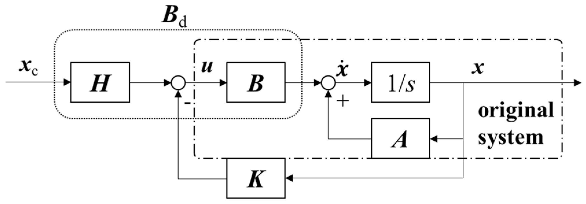
Figure 1. Decoupling control structure utilizing the implicit model.
Drones 09 00565 g001
Figure 2. I&I adaptive control structure of the longitudinal channel.
Drones 09 00565 g002
Figure 3. The asymptotic response and disturbance rejection of longitudinal velocity.
Drones 09 00565 g003
Figure 4. The responses of the pitch and pitch angular rates in the asymptotically stable process.
Drones 09 00565 g004
Figure 5. The control input during the longitudinal velocity response process.
Drones 09 00565 g005
Figure 6. The response process for different values of h.
Drones 09 00565 g006
Figure 7. The response process of pitch and angular velocities for different values of h.
Drones 09 00565 g007
Figure 8. The response process for different values of l.
Drones 09 00565 g008
Figure 9. The response of pitch and angular velocities for different values of l.
Drones 09 00565 g009
Figure 10. Reference trajectory for the sidestep maneuver.
Drones 09 00565 g010
Figure 11. Response process of lateral velocity, roll angle, and angular velocity of sidestep.
Drones 09 00565 g011
Figure 12. Roll angle at 1.5 s of the lateral motion sub-process.
Drones 09 00565 g012
Figure 13. The reference trajectory for the pirouette.
Drones 09 00565 g013
Figure 14. Simulation results of position tracking for the pirouette.
Drones 09 00565 g014
Figure 15. Deviation of the heading angle relative to the reference point during the pirouette maneuver.
Drones 09 00565 g015
Table 1. Performance and actual response of the sidestep process.
Desired PerformanceGood Visual Environments [18]Actual Response
Upon initiating the maneuver, a roll angle change of at least X degrees must be achieved within 1.5 s25°41.11°/41.08°
Achieve a target airspeed of X knots40 knots40 knots
Upon commencing deceleration, a roll angle change of at least X degrees must be achieved within 1.5 s30°41.09°/41.09°
Maintain a selected reference point on the rotorcraft within ±X ft of the ground reference line10 ft0
Maintain altitude within ±X ft at a selected altitude below 30 ft10 ft0
Maintain heading within ±X deg10°0
Disclaimer/Publisher’s Note: The statements, opinions and data contained in all publications are solely those of the individual author(s) and contributor(s) and not of MDPI and/or the editor(s). MDPI and/or the editor(s) disclaim responsibility for any injury to people or property resulting from any ideas, methods, instructions or products referred to in the content.