Article

Dynamic Obstacle Perception Technology for UAVs Based on LiDAR

1
College of Computer Science and Technology, Nanjing University of Aeronautics and Astronautics, Nanjing 211106, China
2
School of Aeronautic Science and Engineering, Beihang University, Beijing 100191, China
*
Author to whom correspondence should be addressed.
Drones 2025, 9(8), 540; https://doi.org/10.3390/drones9080540 (registering DOI)
Submission received: 11 June 2025 / Revised: 18 July 2025 / Accepted: 24 July 2025 / Published: 31 July 2025

Abstract

With the widespread application of small quadcopter drones in the military and civilian fields, the security challenges they face are gradually becoming apparent. Especially in dynamic environments, the rapidly changing conditions make the flight of drones more complex. To address the computational limitations of small quadcopter drones and meet the demands of obstacle perception in dynamic environments, a LiDAR-based obstacle perception algorithm is proposed. First, accumulation, filtering, and clustering processes are carried out on the LiDAR point cloud data to complete the segmentation and extraction of point cloud obstacles. Then, an obstacle motion/static discrimination algorithm based on three-dimensional point motion attributes is developed to classify dynamic and static point clouds. Finally, oriented bounding box (OBB) detection is employed to simplify the representation of the spatial position and shape of dynamic point cloud obstacles, and motion estimation is achieved by tracking the OBB parameters using a Kalman filter. Simulation experiments demonstrate that this method can ensure a dynamic obstacle detection frequency of 10 Hz and successfully detect multiple dynamic obstacles in the environment.

1. Introduction

Drones have become indispensable tools in both military and civilian applications, widely used for their high cost-effectiveness and ease of operation. In particular, quadcopter drones are favored for their simple structure, flexible control, vertical takeoff and landing capabilities, and adaptability to ultra-low altitude and indoor flight, which makes them especially popular in the consumer market. However, with the increasing use of small quadcopter drones in low-altitude environments—particularly in complex dynamic environments with dense obstacles, such as urban and forest areas—their flight safety has become a key factor to prioritize. Therefore, there is an urgent need for an obstacle perception algorithm suitable for dynamic environments to ensure the safety of autonomous drone flight [1].
Currently, drone obstacle avoidance technology primarily focuses on static environments [2,3,4,5]. These methods update the representation of the flight environment in real time but are ineffective for handling moving obstacles. To achieve dynamic obstacle perception, current research mainly employs methods based on event cameras and image-based techniques. Event camera-based methods [6,7,8] can quickly detect dynamic obstacles but are unable to perceive static ones. Additionally, the high cost of event cameras limits their application in small drones. Image-based target recognition methods [9,10,11,12] can detect specific moving targets, such as pedestrians or vehicles but are limited to detecting predefined classes of moving targets. Similarly, image-based semantic segmentation methods [13,14,15] perform semantic segmentation on images obtained from sensors, distinguishing dynamic and static obstacles by recognizing semantic information. However, these algorithms are difficult to run in real time on the limited onboard computational resources of small drones.
With advancements in technology, 3D LiDAR has become more lightweight and affordable. This has allowed LiDAR sensors to be widely used in the field of drones [16,17,18]. Currently, LiDAR is not only utilized in aerial surveying, urban planning, and environmental monitoring but it has also started to play an important role in fields such as autonomous driving and intelligent transportation. The advantages of LiDAR lie in its ability to obtain high-precision point cloud maps with a long perception range. Therefore, current methods involve acquiring scanning point cloud data of the environment through 3D LiDAR and processing it to perceive information about static and dynamic obstacles in real time.
Recently, some scholars have utilized point clouds obtained from sensors for dynamic environment perception. For instance, references [19,20,21] generate environmental point clouds using depth maps acquired from depth cameras, while reference [22] performs point cloud clustering based on both point cloud and color features to differentiate between dynamic and static obstacles. Methods in references [23,24] employ learning-based approaches to quickly segment dynamic and static obstacle point clouds. However, these methods are limited by the field of view of depth cameras, which means they can only perceive dynamic obstacles within a relatively close range.
To address this, we propose a dynamic obstacle perception technology for drones based on 3D LiDAR. First, the method is developed based on the scanning characteristics of LiDAR, enabling efficient segmentation and extraction of obstacle point clouds in the environment. Secondly, the method distinguishes between dynamic and static point clouds based on the motion attributes of 3D points. Finally, an oriented bounding box (OBB) is used to simplify the representation of the spatial position and shape of dynamic obstacle point clouds, while a Kalman filter tracks the OBB parameters to estimate the motion of dynamic obstacles.

2. LiDAR Point Cloud Preprocessing

The LiDAR employed in this study, Livox AVIA (Livox Technology Co., Ltd., Shenzhen, Guangdong, China), utilizes a non-repetitive scanning pattern, which results in a point cloud distribution that is dense in the center and sparse at the edges within any given accumulation time. As scanning continues, the density and coverage of the point cloud gradually increase across the field of view, ultimately forming a dense and image-like representation.
To ensure sufficient and informative point cloud data, preprocessing is required to generate a uniform and dense point cloud map. This involves two key steps: (1) accumulating laser scans to enhance coverage and density at the field-of-view edges for effective obstacle perception, and (2) down-sampling the central region to remove redundancy while preserving essential structural features. Furthermore, ground segmentation is necessary to prevent undesired connections between different obstacle clusters.

2.1. LiDAR Point Cloud Accumulation

Let R l ( t ) and P l t represent the attitude and position of the LiDAR at time t, respectively. Let p c d l t i denote the coordinates of the i-th scan point in the LiDAR coordinate system at time t and p c d w t represent the coordinates of the accumulated point cloud in the world coordinate system at time t. The coordinate transformation relationship is then given by:
p c d w t = t Δ t t   i   R l t p c d l t i + P l t
By using Equation 1 , the point clouds obtained from LiDAR scans with a time interval of t   =   0.1   s are accumulated to achieve a sufficiently dense accumulated point cloud.

2.2. LiDAR Point Cloud Filtering and Segmentation

At the same time, since the accumulated dense point cloud is still uneven at this stage, voxel filtering is required to obtain a more uniform point cloud distribution. This paper adopts the voxel center filtering method. In this method, an approximate bounding cube is calculated based on the input point cloud. The smallest cubic unit defined within the bounding cube is the voxel. In each voxel, only the point closest to the voxel center is retained as the representative point, and the positions of other points within the voxel are disregarded. Compared to voxel-centroid and voxel-nearest-point filtering, voxel-center filtering is simpler and more efficient, saving computational resources.
To facilitate subsequent algorithms in segmenting different moving objects within the point cloud, the filtered point cloud is segmented using random sample consensus (RANSAC) [25] to extract the ground point cloud, avoiding connections between moving objects and the ground itself. The specific process is as follows: first, three points are randomly selected from the point cloud below a height of 0.3 m to fit a plane, and the distance between this plane and other points in the point cloud is calculated. If the distance is less than a certain threshold, the point is considered an inlier of the plane. The algorithm searches for the plane with the most inliers within a limited number of iterations. Since the ground is the most prominent plane in the point cloud, segmenting the fitted plane and its inliers allows the separation of the ground point cloud from the obstacle point cloud.

3. Construction of LiDAR-Based Perception Algorithms

Based on the preprocessed LiDAR point cloud data, a LiDAR-based dynamic obstacle perception algorithm is proposed. This perception algorithm consists of three stages: obstacle extraction, classification into static and dynamic obstacles, and tracking of dynamic obstacles. First, the LiDAR point cloud data undergo accumulation, filtering, and clustering to segment and extract obstacle information. Next, an obstacle motion classification algorithm based on the motion attributes of 3D points is developed to distinguish dynamic from static point clouds. Finally, the oriented bounding box (OBB) method simplifies the representation of the spatial position and shape of dynamic point cloud obstacles. The motion estimation of dynamic obstacles is achieved by tracking the OBB parameters using a Kalman filter.

3.1. Point Cloud Clustering

In the first stage, this study performs clustering analysis on the filtered point cloud data at time t using the density-based spatial clustering of applications with noise (DBSCAN) [26] algorithm. The goal of this step is to divide the point cloud data into different clusters, forming a set of multiple point cloud clusters C t = { c t 1 , c t 2 , , c t m } . Each point cloud cluster represents a group of related positional data points, corresponding to a single object or a group of closely related objects.
Since the DBSCAN algorithm can automatically identify noise points in the data and find regions of different densities without requiring a predefined number of clusters, it is well-suited for point cloud clustering. The point cloud clustering algorithm effectively groups points into meaningful clusters, providing strong support for the subsequent identification and tracking of dynamic obstacles. The process of the point cloud clustering algorithm is shown in Algorithm 1. This method effectively partitions the point cloud into semantically relevant objects, with each object corresponding to an independent cluster. The formation of these clusters allows for a clearer capture of objects in the environment while filtering out a significant number of noise points. Figure 1 illustrates the clustering results obtained using the DBSCAN algorithm. In this figure, each color represents a different cluster, core points are shown with larger markers, border points with smaller markers, and noise points are marked in black. This visual representation clearly demonstrates how DBSCAN groups densely connected points while identifying outliers that do not belong to any cluster.
Algorithm 1: Point cloud clustering algorithm process
Input: point cloud pcl, search radius ε , minimum number of points minPts
Output: clustering results C t = { c t 1 , c t 2 , , c t m }
 1: Foreach p in pcl do
 2:  if p.cluster_id undefined then continue
 3:  Neighbor N RangeQuery(pcl, p, ε )
 4:  if |N| < minPts then
 5:   p.cluster_id Noise
 6:   continue
 7:  id next cluster id
 8:  p.cluster_id id
 9:  Seed set S N/{p}
 10:  Foreach q in S do
 11:    if q.cluster_id = Noise then q.cluster_id id
 12:    if q.cluster_id undefined then continue
 13:    Neighbors N RangeQuery(pcl, q, ε )
 14:    q.cluster_id id
 15:    if |N| < minPts then continue
 16:    S S N

3.2. Generation of Grids

After completing the point cloud cluster process in the previous stage, dynamic and static objects can be classified based on these clusters representing obstacles. For moving obstacles, the point cloud observed in each frame should exhibit significant displacement in the world coordinate system compared to static objects. Therefore, the motion of points within each cluster can be used to determine whether the object represented by the cluster is dynamic or static. Similar to the work carried out by Thomas Eppenberger [21] and Wang [19] on autonomous vehicle and drone platforms, this section develops a dynamic point cloud cluster identification strategy based on point motion properties, with adjustments made to accommodate the scanning characteristics of the Livox AVIA LiDAR. The algorithm process is shown in Algorithm 2.
For each point in a point cloud cluster, its motion state is estimated by calculating the displacement d between the current frame and a previous frame separated by δ seconds. Notably, for points located at the edges of moving objects, the displacement d tends to be significantly larger. When this displacement is converted to velocity, the criterion can be formalized as d / δ > l N N where l N N denotes a predefined velocity threshold. To ensure that the displacement of dynamic object points substantially exceeds that caused by measurement noise, the temporal interval δ must not be too short. However, an excessively large δ can hinder the accurate association of point correspondences between frames. A point cloud cluster C t i is classified as dynamic if the proportion or absolute number of dynamic points within it exceeds a predefined threshold. Each cluster identified as dynamic is then treated as an individual moving object. Otherwise, it is classified as static. Clusters that exhibit fluctuating classifications within a short temporal window are labeled as uncertain.
Algorithm 2: Dynamic point cloud cluster identification strategy based on point motion properties
Input: point cloud cluster C t = { c t 1 , c t 2 , , c t m } , point cloud at t δ seconds p c l w o r l d t δ
Input: point velocity threshold l N N , absolute threshold l d y n a b s , relative threshold l r e l a b s
Output: clustering results l a b e l ( C t )
 1: Foreach cluster c in  C t do
 2:  Count dyn, total reset
 3:  Foreach point p in c do
 4:   if not Is_valid(p) then continue
 5:   total total + 1
 6:   Velocity v   Distance ( p , p c l w o r l d t δ ) / δ
 7:   if  v > l N N then dyn dyn + 1
 8:  if dyn l d y n a b s or dyn l r e l a b s t o t a l then
 9:   label(c) dynamic
 10:   if not Is_consistent(c) then
 11:    label(c) uncertain
Since the core of this method lies in measuring the displacement of individual points across two frames, the motion state of points in the point cloud cluster C t i can only be determined if those points are observed in both the current frame C t i and the world-aligned point cloud p c d w o r l d t δ from δ seconds earlier. Consequently, it is necessary to assess the validity of each point, and the evaluation strategy is as follows:
(1) Points in non-overlapping regions of the field of view
During UAV flight, changes in the field of view (FOV) may occur due to platform motion, resulting in some points being observed only once. Therefore, points located in non-overlapping FOV regions between the two frames must be excluded.
(2) Occluded points
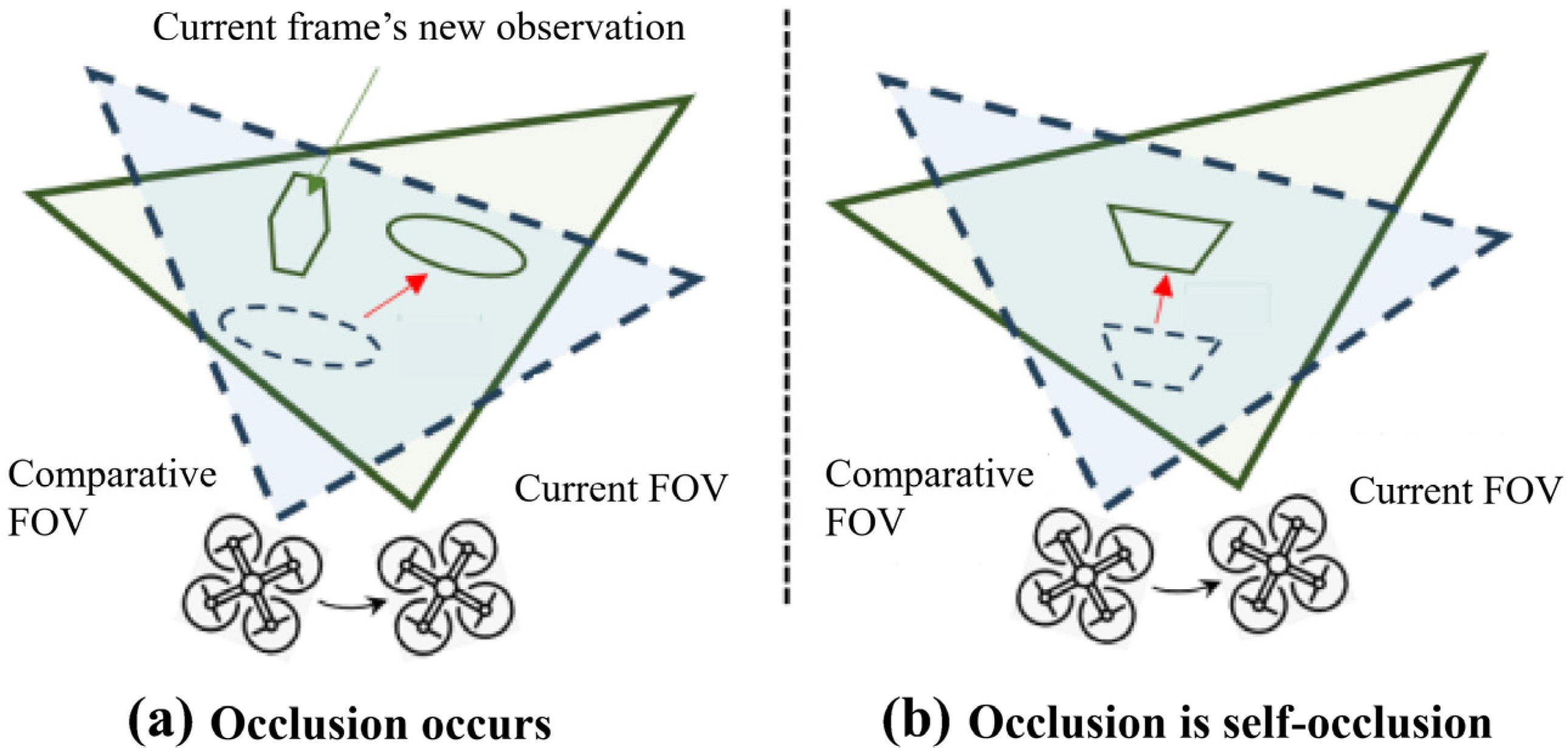
As illustrated in Figure 2, if a point cloud cluster C visible in the current frame is occluded by a foreground object A in the previous frame, all points in C are considered invalid, unless A corresponds to the tracking cluster of C in the earlier frame. Occlusion is determined by projecting the cluster C onto FOV of the UAV at time t δ :
Let p w o r l d denote the 3D world coordinates of a point p C t i , and let p f o v t δ be its coordinates in the drone’s camera frame at time t δ , given the pose ( R t δ , P t δ ) . The projection onto the normalized image plane yields 2D coordinates u p , v p , with the corresponding depth d e p t h [ p ] t δ . All points in p c d w o r l d t δ are similarly projected onto the same plane. A 2D nearest neighbor search is then performed to find the closest projected point q at u p , v p , along with its associated depth d e p t h q t δ .
Moreover, due to the non-repetitive scanning pattern of the AVIA LiDAR, it is challenging to ensure that the same point is observed in both frames. Therefore, a more robust strategy is to compute the distance d from the points in the current frame to the local plane formed by its nearest neighbors in the dense point cloud p c d w o r l d t δ from δ seconds ago:
p f o v t δ = R t δ     p w o r l d + P t δ d e p t h p t δ = p f o v t δ 0 0 1 u p , v p , d e p t h p t δ T = p f o v t δ d i a g o n a l 1 d e p t h p t δ 1 d e p t h p t δ 1
Let the plane equation formed by the nearest neighbor point set of point p , X = { x 1 , x 2 , , x n } , be:
A x + B y + C z + D = 0
Then the following expression holds:
k 1 , n , n T x ~ k   =   0
where x ~ k   =   [ x T , 1 ] T is the homogeneous coordinate of the nearest neighbor spatial point, and x ~ k   =   [ x T , 1 ] T represents the plane parameters.
At this point, we can formulate the following least squares problem and obtain the least squares solution for the nearest neighbor plane parameters:
m i n n X ~ T n   2 2
where X ~ = [ x ~ 1 , , x ~ n ] is the set of homogeneous coordinates for the nearest neighbor point set. Subsequently, we can calculate the distance d from point p to the plane:
d = A x + B y + C z + D A 2 + B 2 + C 2
d can be considered as the distance that point p has moved within δ seconds, which allows us to calculate the motion speed of the entire point cloud and use it as a criterion to determine whether the point cloud cluster is dynamic.

3.3. Representation and Tracking of Dynamic Point Cloud

Once the point cloud clusters representing dynamic objects are obtained, it is essential to convert them into a simplified form suitable for drone obstacle avoidance. Specifically, these clusters are fitted using oriented bounding boxes (OBBs), which are constructed based on the principal axes of inertia of the object. Unlike axis-aligned bounding boxes, OBBs are not constrained to the global coordinate axes, enabling a more compact and accurate representation of the object’s geometric shape and orientation. This enhances collision checking in the drone’s path planning process. After extracting OBBs from each frame, it is crucial to track these bounding boxes across time using a Kalman filter to associate the same moving object across multiple frames and enable accurate motion estimation.
The steps to calculate the OBB are as follows: first, calculate the centroid position of the obstacle point cloud:
C = 1 N i = 1 N p i
Based on the centroid position, the covariance matrix of the point cloud with respect to the centroid can be constructed as c o v ( p i C , p i C ) . If we denote the point set of the point cloud cluster as P = { p 1 , p 2 , , p n } , then:
c o v p i C , p i C = 1 N P C P C T
Perform principal component analysis using the covariance matrix and obtain the corresponding eigenvalues and eigenvectors through singular value decomposition (SVD):
c o v p i C , p i C = U V T
The eigenvalues correspond to the lengths of the long axis, medium axis, and short axis of the OBB, while the eigenvectors represent the direction vectors of the three axes. Based on the direction of the three axes, their lengths, and the centroid position, the corresponding OBB for the point cloud can be determined.
At the initial moment, a Kalman filter will be initialized for tracking all the obtained OBBs, with the motion equations and observation equations defined as follows:
x k + 1 = A x k + N 0 , Q z k = H x k + N 0 , R
Since the center position of the OBB is easily affected by occlusion, when the point cloud in the field of view is partially occluded, the observed center position may experience significant displacement. Based on the rigid body motion assumption, the state variable can be defined as x k = p , R , v , ω T . The dynamics in continuous time can be expressed as follows:
p ˙ = v R ˙ = ω × R v ˙ = 0 ω ˙ = 0
After discretization, it can be expressed as follows:
x i + 1 = x i t f x i , f x i = v i ω i 0 0
Additionally, z k = x k + N 0 , R . This initializes the Kalman filter. When a new set of dynamic OBBs is observed, they will be matched with the existing Kalman filters.
The matching process is illustrated in Figure 3. First, all Kalman filters in K t i 1 are used to predict the current state, resulting in the predicted states K t i | t i 1 . Then, the center c t i i of each bounding box from the current frame t i is matched to the predicted centers K t i | t i 1 using the nearest neighbor algorithm. If the center c t i i is successfully matched, the corresponding point cloud cluster C t i inherits the tracking history of its matched Kalman filter. If c t i i cannot be matched with any predicted center, it is treated as a newly appeared object, and a new Kalman filter κ t i l is initialized for it. To handle short-term occlusion, unmatched bounding boxes are marked as “lost”, and their Kalman filters retain their predicted states. If a filter remains in the lost state longer than a predefined threshold t d , it is deleted. This strategy enables the real-time initialization and management of Kalman filters for dynamic targets in the current field of view, thus supporting continuous motion estimation.
When an OBB is successfully matched with an existing Kalman filter, the filter is updated based on the OBB’s current position and geometric parameters. However, as the drone moves and dynamic objects continue to change positions, incomplete point cloud observations can lead to errors in the estimated OBB center, which may cause large discrepancies between the predicted and true positions and velocities. To mitigate this issue, we propose a center correction method that accounts for incomplete observations. Specifically, if the size of the matched OBB significantly differs from the size stored in the filter, the center position is corrected as follows:
c ~ i = c i s k j s c i 2
where s k j and s c i are the sizes of the successfully matched filter and bounding box, respectively, which can be used to correct the centroid position.

4. Experiments and Analysis

4.1. Simulation Platform and Flight Condition Settings

This study utilizes the Gazebo simulator to construct a high-fidelity simulated flight platform. Gazebo is a realistic physics-based simulation tool that provides a comprehensive suite of sensor and UAV models, enabling the realistic simulation of LiDAR-equipped drones operating within complex environments. To evaluate the effectiveness of the proposed method, a simulation environment containing both static obstacles and dynamic pedestrians was developed in Gazebo. Real-time perception was performed using a quadrotor model equipped with a Livox-Avia LiDAR sensor. The simulation ran on a workstation configured with an R9-7945HX CPU (Advanced Micro Devices, Inc., Santa Clara, CA, USA) and an RTX 4060 GPU (NVIDIA Corporation, Santa Clara, CA, USA).
In the simulation environment, quantitative analysis was conducted from both the perspectives of real-time perception effectiveness and motion estimation accuracy. Table 1 presents several key parameter settings and their impact on detection quality. For instance, the maximum effective perception range for dynamic obstacles was set to 12 m to achieve a good balance between detection accuracy and real-time performance, while the minimum effective range determines the system’s ability to detect nearby objects. The number of horizontal and vertical samples affects the spatial resolution and density of the generated point cloud, while the range resolution affects the precision of object localization. These parameters were carefully tuned to balance perception accuracy with computational efficiency in our experiments.

4.2. Comparison of Dynamic Obstacle Detection Results

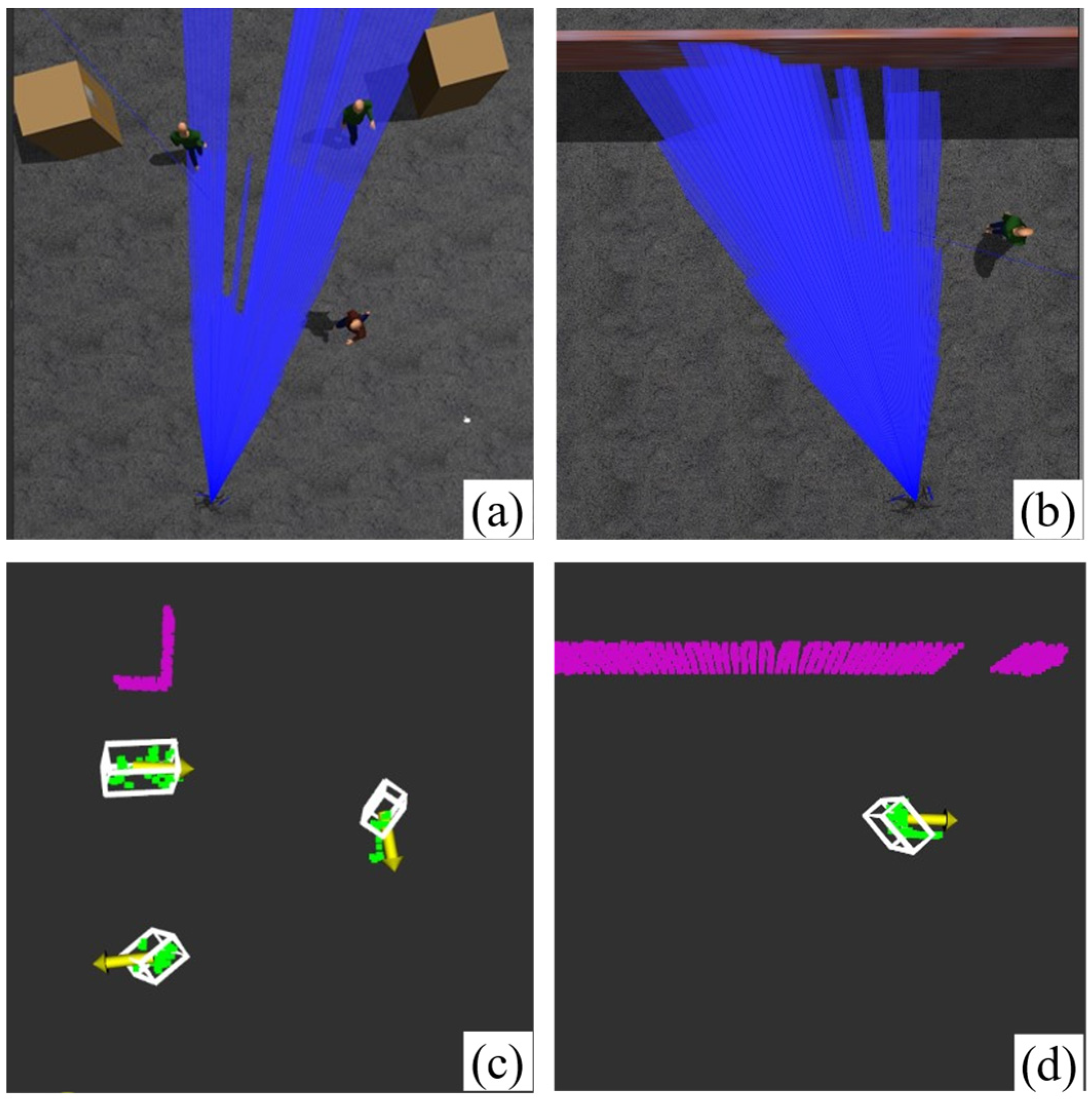
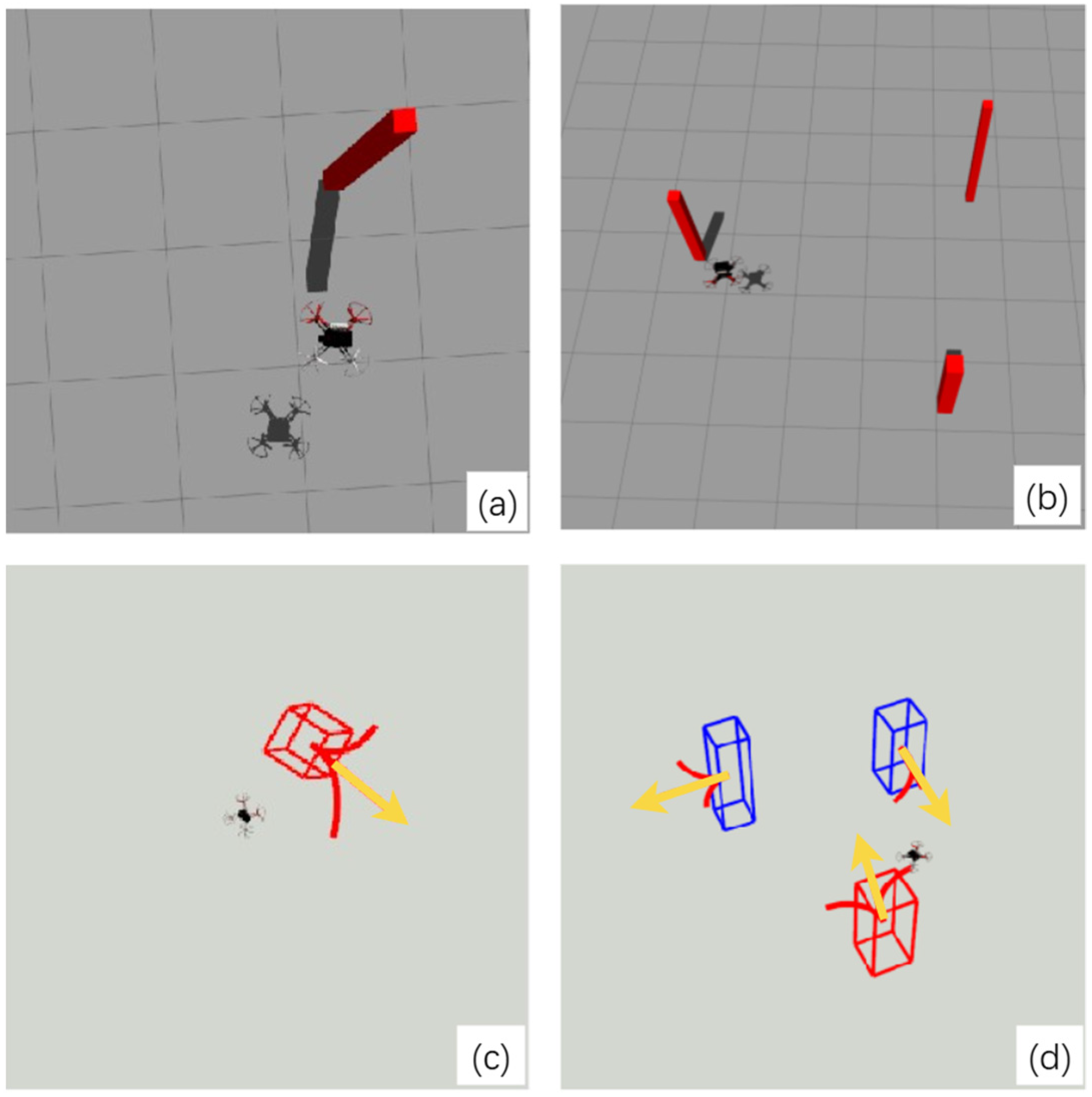
First, a quantitative analysis of the dynamic obstacle detection method proposed in this paper is conducted. In the simulation scenario, multiple pedestrians walking at different speeds are arranged, while the drone flies through and performs real-time detection of these moving targets. The setup of the simulation environment is shown in Figure 4a, where three randomly walking pedestrians are present, along with several fixed static obstacles serving as occlusions. The drone is set to fly at a speed of 1 m/s and perceives the environment using LiDAR. Figure 4c displays the real-time detection of dynamic obstacles. On the detection screen, red represents the static point cloud segmented after perception, green indicates the dynamic point cloud, and the white boxes represent the OBBs generated based on the dynamic point cloud. From the figure, it can be seen that the method proposed in this paper accurately distinguishes the point clouds of walking pedestrians as dynamic and constructs the OBBs. In addition, Figure 5 presents another scenario where a rectangular cuboid dynamic obstacle is included in the simulation environment to further demonstrate the effectiveness of the proposed perception and clustering method under more diverse obstacle conditions.
At the same time, the performance of dynamic obstacle detection is measured using the multiple objects tracking accuracy (MOTA) metric defined in [27]. This metric is calculated from three sub-metrics: the miss rate f n of undetected dynamic obstacles, the false positive rate f p of static targets detected as dynamic obstacles, and the mismatch rate f m of dynamic obstacles between frames. The calculation is given by: MOTA = 1 ( f n + f p + f m ) . Therefore, a higher MOTA value indicates better performance of the method in dynamic obstacle detection. The method proposed in this paper is compared with the methods from [19,21], with the results shown in Table 2 indicating that the method presented in this study achieves better performance in dynamic detection.

4.3. Comparison of Motion Estimation Accuracy

To evaluate the accuracy of the proposed motion estimation method, a simulation environment was constructed in which a pedestrian walks at varying speeds. The real-time tracking algorithm was employed to estimate the pedestrian’s position and velocity. As shown in Figure 4b, the pedestrian walks back and forth along a wall at 1.5 m/s. Real-time detection results of dynamic obstacles are illustrated in Figure 4d. Estimation errors were calculated by comparing estimated position and velocity with ground-truth values, and the results were compared with those of the method in [28], as presented in Table 3. The results demonstrate that the proposed method achieves significantly lower errors in both position and velocity estimation. An intuitive comparison of velocity estimation is presented in Figure 6, illustrating that the proposed method can effectively correct errors in velocity estimation caused by inaccuracies in position observations. This enables more accurate velocity estimation during continuous tracking.

4.4. Flight Test Validation

To further demonstrate the feasibility of the proposed method, dynamic obstacle perception experiments were conducted in a real flight environment using a quadrotor UAV equipped with a LiDAR sensor and an onboard NUC computer. As shown in Figure 7, the flight platform is a quadrotor UAV with a 330 mm frame size, integrated with the CUAV V6X flight controller, which combines essential components such as motors and receivers. The proposed algorithm is deployed on the onboard NUC computer and operates in real time during flight. To verify that the algorithm enables real-time dynamic obstacle perception, a comprehensive flight experiment was conducted. During the experiment, a ground station controlled the UAV to fly within a test environment, while the onboard LiDAR and perception algorithm continuously sensed the surroundings and output environmental information in real time.
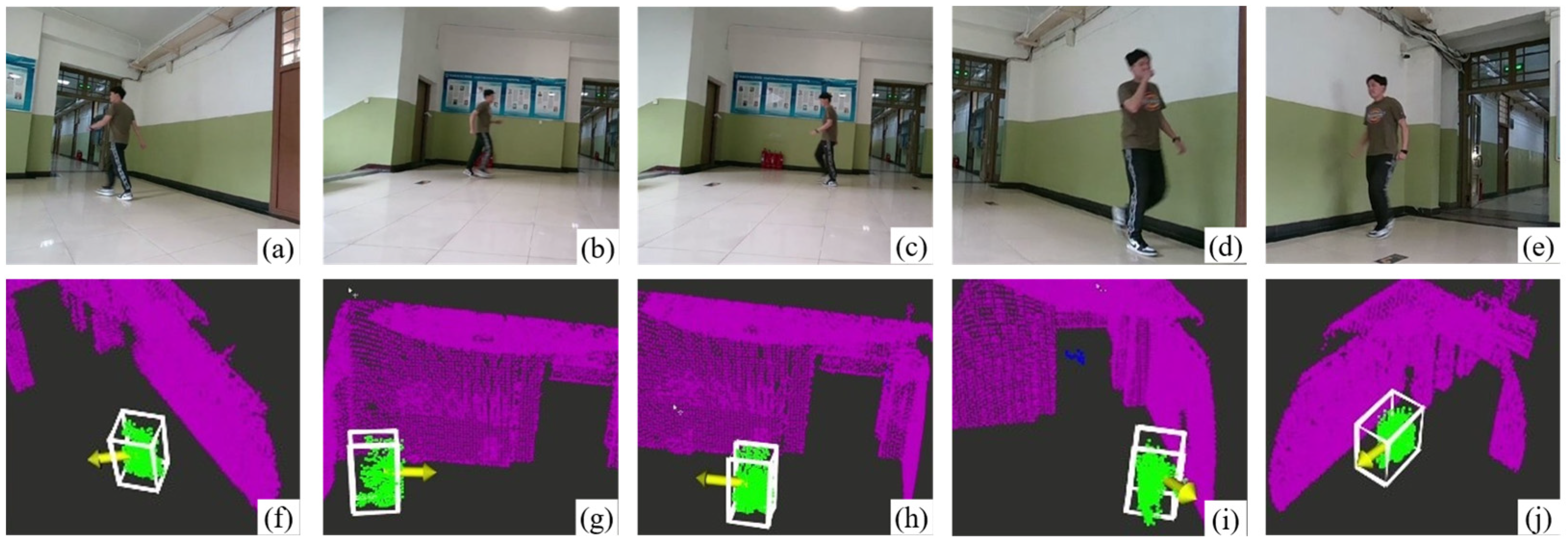
The entire experiment process was recorded using the onboard camera of the UAV, as illustrated in Figure 8a–e. In this scenario, a pedestrian moves at a constant speed within an indoor environment, while the UAV simultaneously perceived the surrounding environment during flight. Figure 8f–j show the corresponding program interface output of the dynamic obstacle perception results. The results demonstrate that the proposed algorithm enables real-time perception of moving obstacles traveling at a constant speed.
To further assess the robustness of the algorithm, experiments were conducted in an outdoor complex environment where multiple pedestrians exhibited varying motion patterns, including walking and running, as shown in Figure 9a–d. In Figure 9a, a pedestrian rapidly moves from right to left, while Figure 9d shows three moving pedestrians simultaneously. In these two relatively challenging test scenarios, the algorithm successfully tracked dynamic obstacles, confirming its practical applicability and stable performance in real-world conditions.

5. Conclusions

This paper focuses on the dynamic perception problem in UAV obstacle avoidance within dynamic environments and proposes a LiDAR-based dynamic obstacle perception method. The results are validated through simulations and real-world experiments, which indicate that:
(1)
The proposed method achieves good dynamic obstacle perception results in simulation environments, demonstrating an improvement of approximately 15–20% in dynamic obstacle detection and motion estimation compared to previously proposed methods.
(2)
Flight tests demonstrate the effectiveness and practicality of the proposed LiDAR-based dynamic obstacle perception algorithm, which maintains robust perception capabilities in complex outdoor dynamic scenes, including random pedestrian movements and multiple moving pedestrians.
Future work will focus on developing obstacle avoidance algorithms that leverage dynamic obstacle perception, enabling UAVs to effectively avoid obstacles during flight in dynamic environments.

Author Contributions

Conceptualization, W.X. and F.S.; methodology, W.X. and Z.P.; software, W.X.; validation, W.X., Z.P. and F.S.; formal analysis, W.X. and F.S.; investigation, W.X.; resources, W.X. and F.S.; data curation, W.X. and Z.P.; writing—original draft preparation, W.X.; writing—review and editing, W.X. and F.S.; visualization, W.X. and F.S.; supervision, F.S. All authors have read and agreed to the published version of the manuscript.

Funding

This work was supported by the Fundamental Research Funds for the Central Universities (Grant No. NS2024055).

Data Availability Statement

The original contributions presented in the study are included in the article, further inquiries can be directed to the corresponding author.

Conflicts of Interest

The authors declare no conflicts of interest.

References

  1. Lu, L.; Fasano, G.; Carrio, A.; Lei, M.; Bavle, H.; Campoy, P. A comprehensive survey on non-cooperative collision avoidance for micro aerial vehicles: Sensing and obstacle detection. J. Field Robot. 2023, 40, 1697–1720. [Google Scholar] [CrossRef]
  2. Zhou, X.; Wang, Z.; Ye, H.; Xu, C.; Gao, F. Ego-planner: An esdf-free gradient-based local planner for quadrotors. IEEE Robot. Autom. Lett. 2020, 6, 478–485. [Google Scholar] [CrossRef]
  3. Zhou, B.; Gao, F.; Wang, L.; Liu, C.; Shen, S. Robust and efficient quadrotor trajectory generation for fast autonomous flight. IEEE Robot. Autom. Lett. 2019, 4, 3529–3536. [Google Scholar] [CrossRef]
  4. Yu, Q.; Qin, C.; Luo, L.; Liu, H.; Hu, S. CPA-Planner: Motion Planner with Complete Perception Awareness for Sensing-Limited Quadrotors. IEEE Robot. Autom. Lett. 2022, 8, 720–727. [Google Scholar] [CrossRef]
  5. Zhang, X.; Lu, J.; Hui, Y.; Shen, H.; Xu, L.; Tian, B. Rapa-planner: Robust and efficient motion planning for quadrotors based on parallel ra-mppi. IEEE Trans. Ind. Electron. 2024, 72, 7149–7159. [Google Scholar] [CrossRef]
  6. Davide, F.; Kevin, K.; Davide, S. Dynamic obstacle avoidance for quadrotors with event cameras. Sci. Robot. 2020, 5, 13–27. [Google Scholar] [CrossRef]
  7. He, B.; Li, H.; Wu, S.; Wang, D.; Zhang, Z.; Dong, Q.; Xu, C.; Gao, F. Fast-dynamic-vision: Detection and tracking dynamic objects with event and depth sensing. In Proceedings of the 2021 IEEE/RSJ International Conference on Intelligent Robots and Systems (IROS), Prague, Czech Republic, 27 September–1 October 2021; IEEE Press: Piscataway, NJ, USA, 2021; pp. 3071–3078. [Google Scholar]
  8. Iddrisu, K.; Shariff, W.; Corcoran, P.; O’Connor, N.E.; Lemley, J.; Little, S. Event camera based eye motion analysis: A survey. IEEE Access 2024, 12, 136783–136804. [Google Scholar] [CrossRef]
  9. Lin, J.; Zhu, H.; Alonso-Mora, J. Robust vision-based obstacle avoidance for micro aerial vehicles in dynamic environments. In Proceedings of the 2020 IEEE International Conference on Robotics and Automation (ICRA), Paris, France, 31 May–31 August 2020; IEEE Press: Piscataway, NJ, USA, 2020; pp. 2682–2688. [Google Scholar]
  10. Oleynikova, H.; Honegger, D.; Pollefeys, M. Reactive avoidance using embedded stereo vision for MAV flight. In Proceedings of the 2015 IEEE International Conference on Robotics and Automation (ICRA), Seattle, DC, USA, 26–30 May 2015; IEEE Press: Piscataway, NJ, USA, 2015; pp. 50–56. [Google Scholar]
  11. Tai, L.; Li, S.; Liu, M. A deep-network solution towards model-less obstacle avoidance. In Proceedings of the 2016 IEEE/RSJ International Conference on Intelligent Robots and Systems (IROS), Daejeon, Republic of Korea, 9–14 October 2016; IEEE Press: Piscataway, NJ, USA, 2016; pp. 2759–2764. [Google Scholar]
  12. Xu, Z.; Shi, H.; Li, N.; Xiang, C.; Zhou, H. Vehicle detection under UAV based on optimal dense YOLO method. In Proceedings of the 2018 5th International Conference on Systems and Informatics (ICSAI), Nanjing, China, 10–12 November 2018; IEEE Press: Piscataway, NJ, USA, 2018; pp. 407–411. [Google Scholar]
  13. Mori, T.; Scherer, S. First results in detecting and avoiding frontal obstacles from a monocular camera for micro unmanned aerial vehicles. In Proceedings of the 2013 IEEE International Conference on Robotics and Automation, Karlsruhe, Germany, 6–10 May 2013; IEEE Press: Piscataway, NJ, USA, 2013; pp. 1750–1757. [Google Scholar]
  14. Xu, Z.; Zhan, X.; Chen, B.; Xiu, Y.; Yang, C.; Shimada, K. A real-time dynamic obstacle tracking and mapping system for UAV navigation and collision avoidance with an RGB-D camera. In Proceedings of the 2023 IEEE International Conference on Robotics and Automation (ICRA), London, UK, 29 May–2 June 2023; IEEE Press: Piscataway, NJ, USA, 2023; pp. 10645–10651. [Google Scholar]
  15. Li, J.; Li, Y.; Zhang, S.; Chen, Y. Image-point cloud embedding network for simultaneous image-based farmland instance extraction and point cloud-based semantic segmentation. Int. J. Appl. Earth Obs. Geoinf. 2025, 136, 104361. [Google Scholar] [CrossRef]
  16. Shan, T.; Englot, B.; Ratti, C.; Rus, D. Lvi-sam: Tightly-coupled lidar-visual-inertial odometry via smoothing and mapping. In Proceedings of the 2021 IEEE International Conference on Robotics and Automation (ICRA), Xi’an, China, 30 May–5 June 2021; IEEE Press: Piscataway, NJ, USA, 2021; pp. 5692–5698. [Google Scholar]
  17. Ren, Y.; Zhu, F.; Liu, W.; Wang, Z.; Lin, Y.; Gao, F. Bubble planner: Planning high-speed smooth quadrotor trajectories using receding corridor. In Proceedings of the 2022 IEEE/RSJ International Conference on Intelligent Robots and Systems (IROS), Kyoto, Japan, 23–27 October 2022; IEEE Press: Piscataway, NJ, USA, 2022; pp. 6332–6339. [Google Scholar]
  18. Kong, F.; Xu, W.; Cai, Y.; Zhang, F. Avoiding dynamic small obstacles with onboard sensing and computation on aerial robots. IEEE Robot. Autom. Lett. 2021, 6, 7869–7876. [Google Scholar] [CrossRef]
  19. Wang, Y.; Ji, J.; Wang, Q.; Xu, C.; Gao, F. Autonomous flights in dynamic environments with onboard vision. In Proceedings of the 2021 IEEE/RSJ International Conference on Intelligent Robots and Systems (IROS), Prague, Czech Republic, 27 September–1 October 2021; IEEE Press: Piscataway, NJ, USA, 2021; pp. 1966–1973. [Google Scholar]
  20. Tordesillas, J.; How, J.P. PANTHER: Perception-aware trajectory planner in dynamic environments. IEEE Access 2022, 10, 22662–22677. [Google Scholar] [CrossRef]
  21. Eppenberger, T.; Cesari, G.; Dymczyk, M.; Siegwart, R.; Dubé, R. Leveraging stereo-camera data for real-time dynamic obstacle detection and tracking. In Proceedings of the 2020 IEEE/RSJ International Conference on Intelligent Robots and Systems (IROS), Las Vegas, NV, USA, 24 October 2020–24 January 2021; IEEE Press: Piscataway, NJ, USA, 2020; pp. 10528–10535. [Google Scholar]
  22. Chen, H.; Lu, P. Real-time identification and avoidance of simultaneous static and dynamic obstacles on point cloud for UAVs navigation. Robot. Auton. Syst. 2022, 154, 104124. [Google Scholar] [CrossRef]
  23. Chen, X.; Mersch, B.; Nunes, L.; Marcuzzi, R. Automatic labeling to generate training data for online LiDAR-based moving object segmentation. IEEE Robot. Autom. Lett. 2022, 7, 6107–6114. [Google Scholar] [CrossRef]
  24. Mersch, B.; Chen, X.; Vizzo, I.; Nunes, L.; Behley, J.; Stachniss, C. Receding moving object segmentation in 3d lidar data using sparse 4d convolutions. IEEE Robot. Autom. Lett. 2022, 7, 7503–7510. [Google Scholar] [CrossRef]
  25. Fischler, M.A.; Bolles, R.C. Random sample consensus: A paradigm for model fitting with applications to image analysis and automated cartography. Commun. ACM 1981, 24, 381–395. [Google Scholar] [CrossRef]
  26. Ester, M.; Kriegel, H.P.; Sander, J.; Xu, X. A density-based algorithm for discovering clusters in large spatial databases with noise. In Proceedings of the Second International Conference on Knowledge Discovery and Data Mining, Portland, OR, USA, 2–4 August 1996; AAAI Press: Washington, DC, USA, 1996; pp. 226–231. [Google Scholar]
  27. Bernardin, K.; Elbs, A.; Stiefelhagen, R. Multiple object tracking performance metrics and evaluation in a smart room environment. In Proceedings of the Sixth IEEE International Workshop on Visual Surveillance, in Conjunction with ECCV, Graz, Austria, 13 May 2006; Citeseer Press: Princeton, NJ, USA, 2006; p. 90. [Google Scholar]
  28. Cheng, H.; Zhang, X.T.; Fang, Y.Q. Target tracking estimation based on diffusion Kalman filtering algorithm. Comput. Appl. Softw. 2021, 38, 191–197+238. (In Chinese) [Google Scholar]
Figure 1. Pictorial representation of the DBSCAN clustering result.
Drones 09 00540 g001
Figure 2. Field of view changes and occlusion.
Drones 09 00540 g002
Figure 3. The tracking process of clustering centroids.
Drones 09 00540 g003
Figure 4. Detection of randomly walking pedestrians and fixed static obstacles in simulation. (a) Three pedestrians and static boxes; (b) One pedestrian and a static obstacle; (c,d) Corresponding OBBs (white cubes) for (a,b).
Drones 09 00540 g004
Figure 5. Rectangular cuboid dynamic obstacles in simulation. (a) A single dynamic cuboid; (b) Three dynamic cuboids; (c,d) Corresponding OBBs for (a,b), shown as red and blue cubes. Red cubes are closer to the UAV, while blue ones are farther away.
Drones 09 00540 g005
Figure 6. Comparison of speed estimation.
Drones 09 00540 g006
Figure 7. UAV flight test platform.
Drones 09 00540 g007
Figure 8. Dynamic obstacle perception flight test. (ae) Onboard camera views showing a pedestrian in a real environment. (fj) Dynamic obstacle detection results, with white cubes representing OBBs.
Drones 09 00540 g008
Figure 9. Multiple dynamic obstacles’ perception flight test. (ad) Onboard camera views showing multiple pedestrians with different motion patterns in a real environment. (eh) Dynamic obstacle detection results, with white cubes representing OBBs.
Drones 09 00540 g009
Table 1. Key parameter settings and their influence on detection quality.
ParameterValueDescription of Influence on Detection Quality
Maximum Effective Range12 mLimits the perception distance; affects the ability to detect distant obstacles.
Minimum Effective Range0.2 mAffects the system’s ability to perceive nearby objects, which is critical for short-range collision avoidance.
Horizontal Samples300Determines the density of horizontal point cloud; higher values improve object contour resolution.
Vertical Samples40Affects vertical resolution of the point cloud, crucial for detecting obstacles of varying height.
Range Data Resolution0.002 mDefines the precision of distance measurement, influencing localization accuracy.
Table 2. Comparison of dynamic obstacle detection effects.
Dynamic Obstacle DetectionMiss Rate (%)False Positive Rate (%)Mismatch Rate (%)MOTA (%)
Reference 165.49.210.674.8
Reference 187.78.38.675.4
Our method3.55.04.287.3
Table 3. Comparison of motion estimation errors.
Motion Estimation MethodPosition Estimation Errors (m)Speed Estimation Errors (m/s)
[28]0.450.55
Our method0.320.39
Disclaimer/Publisher’s Note: The statements, opinions and data contained in all publications are solely those of the individual author(s) and contributor(s) and not of MDPI and/or the editor(s). MDPI and/or the editor(s) disclaim responsibility for any injury to people or property resulting from any ideas, methods, instructions or products referred to in the content.