
Parametric Modeling and Evaluation of Departure and Arrival Air Routes for Urban Logistics UAVs


Abstract
1. Introduction
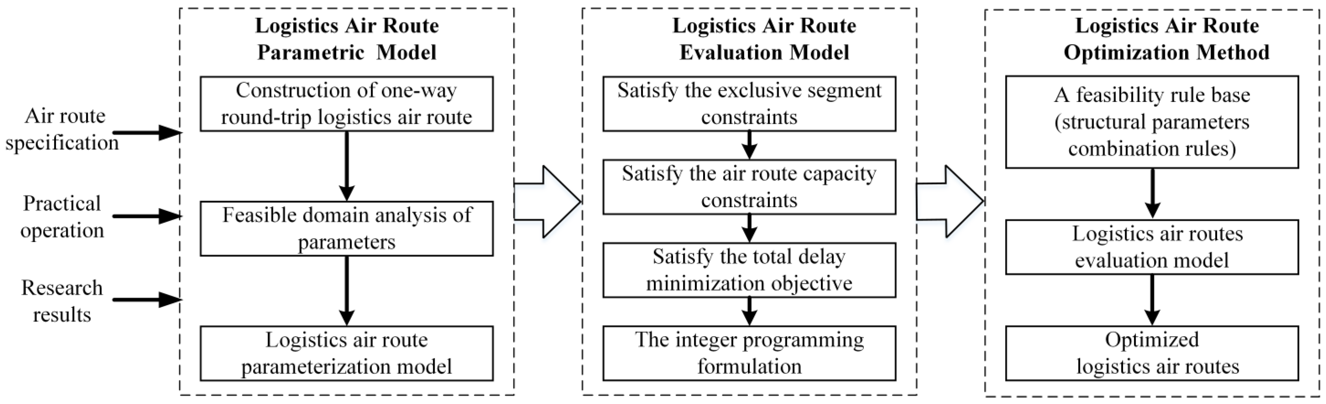
2. Parametric Mode of UAV Logistics Air Routes
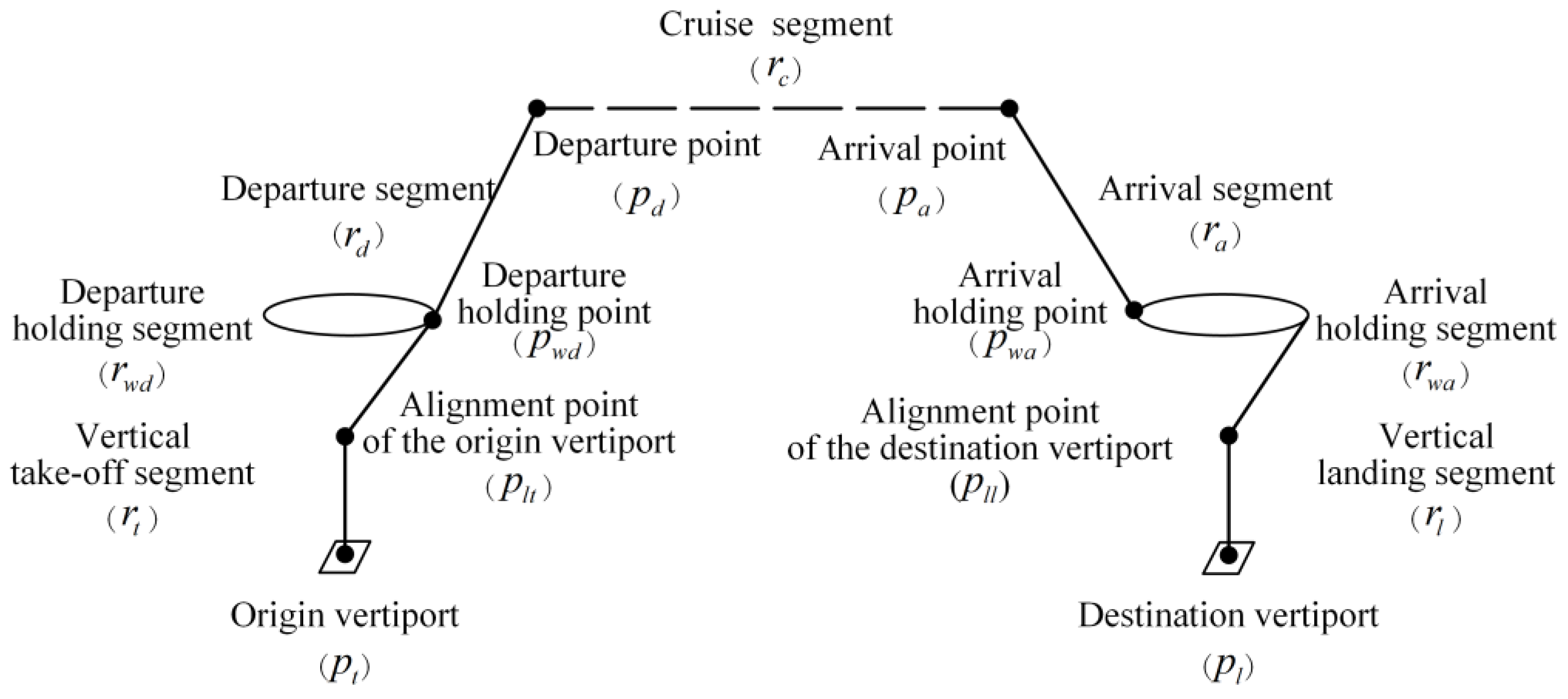
2.1. Composition of Logistics Air Routes
2.2. Parametric Model of Logistics Air Route
3. Evaluation Model of UAV Logistics Air Routes
3.1. Objective Function
3.2. Constraints
3.2.1. Fundamental Operational Constraints
3.2.2. Exclusive Segment Constraints
3.2.3. The Air Route Capacity Constraints
4. Logistics Air Route Optimization Method
4.1. Determining the Basic Configurations
4.2. Definition of Feasibility Rule Base
4.3. Optimization Process
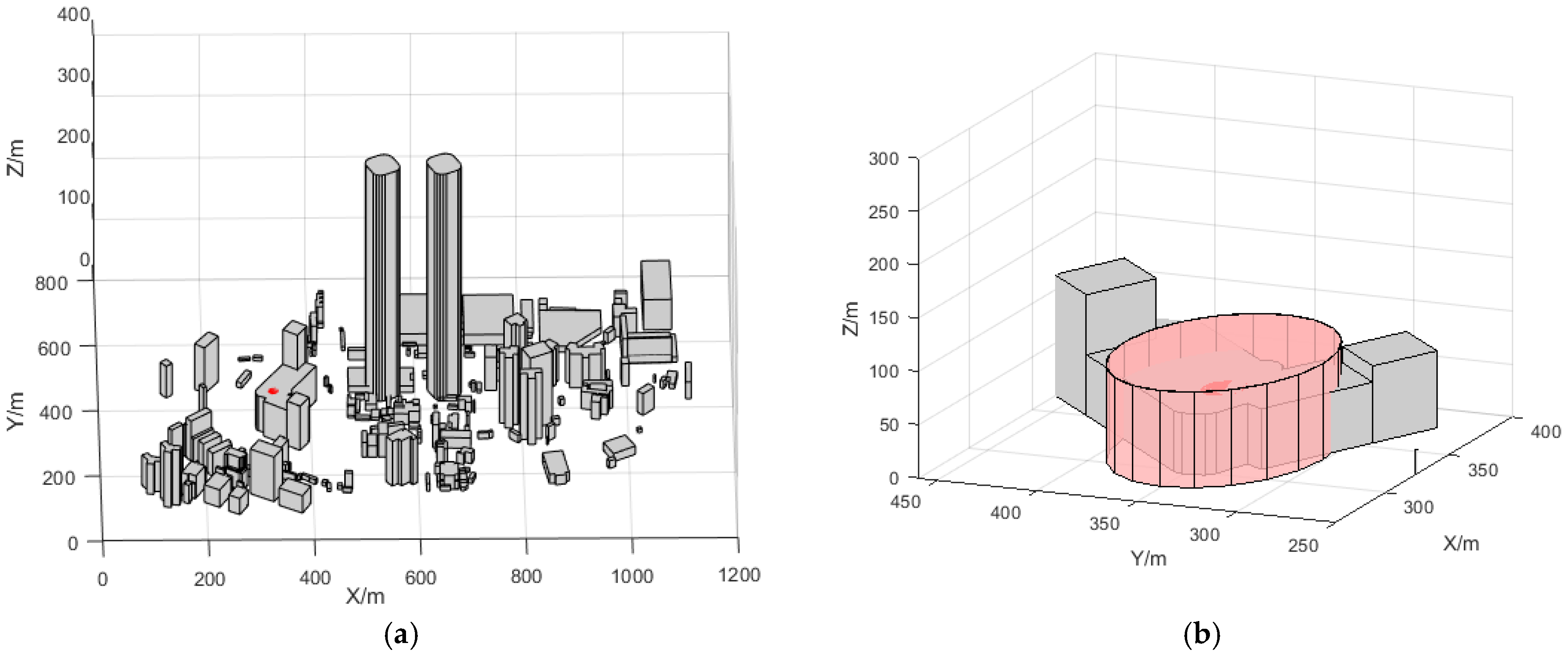
5. UAV Logistics Air Route Optimization Case Study
5.1. Parameter Selection
- (1)
- Operational Airspace Parameters for Departure and Arrival Air Routes
- (2)
- Operational Parameters
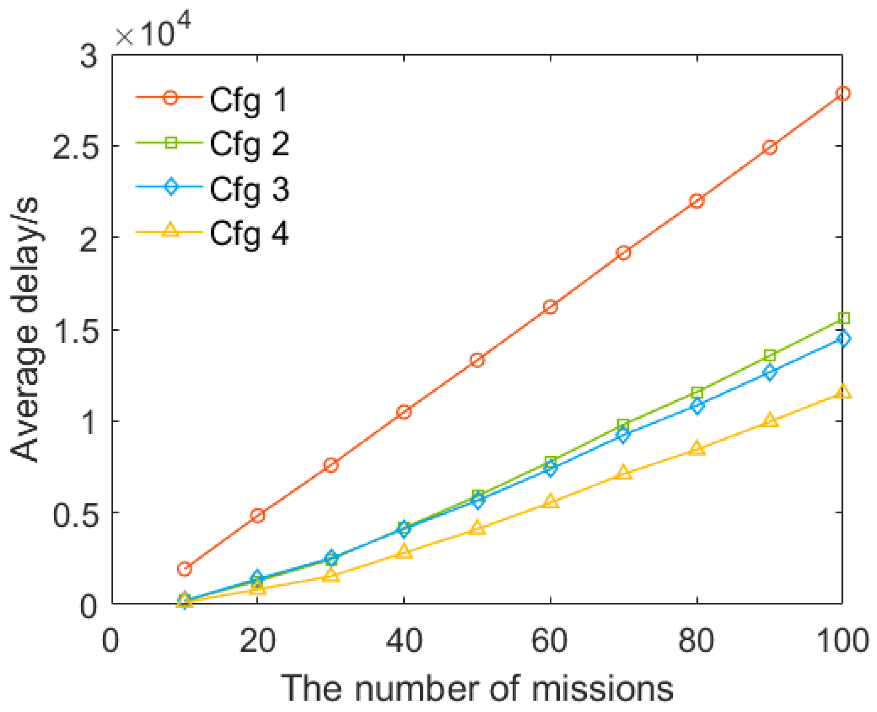
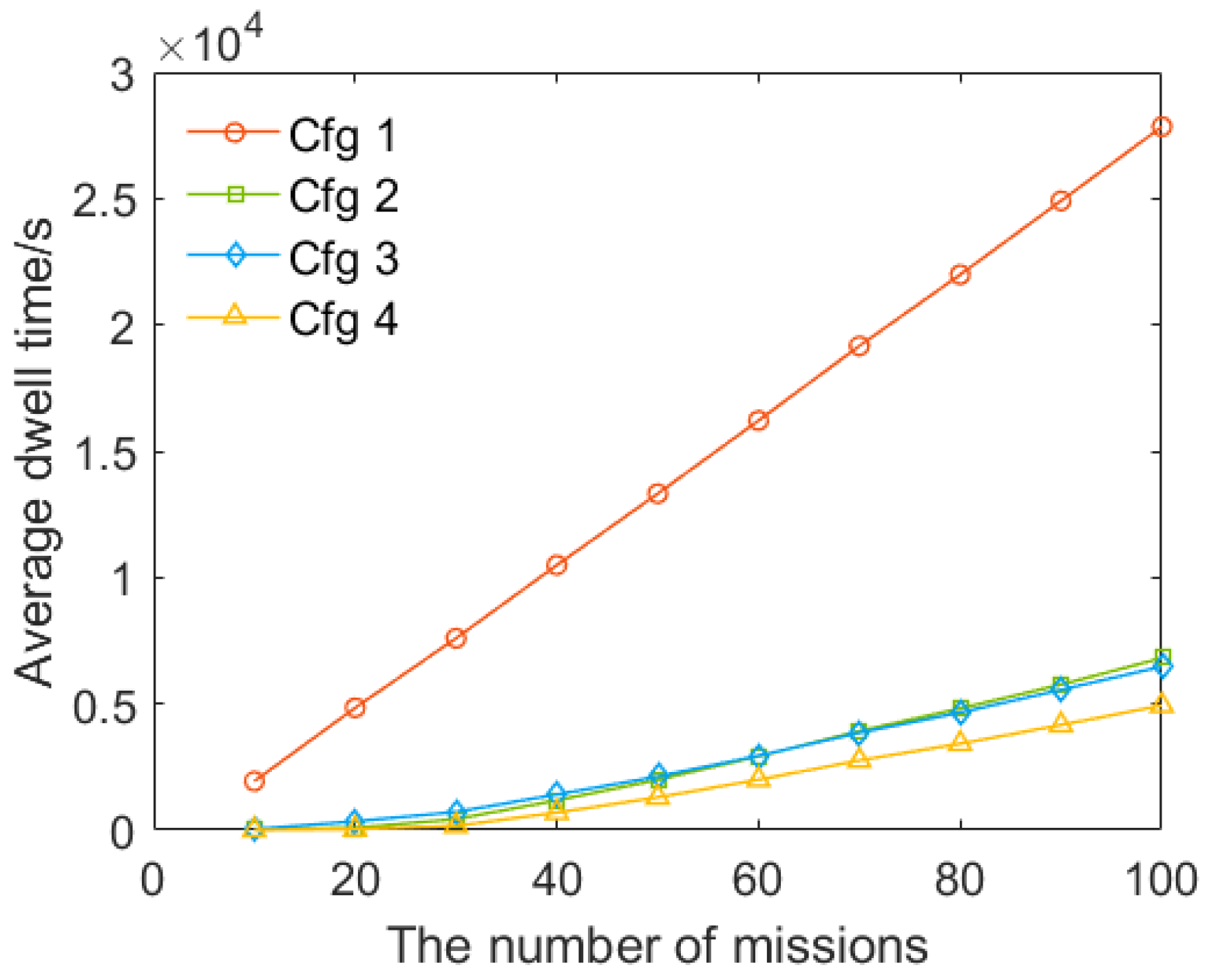
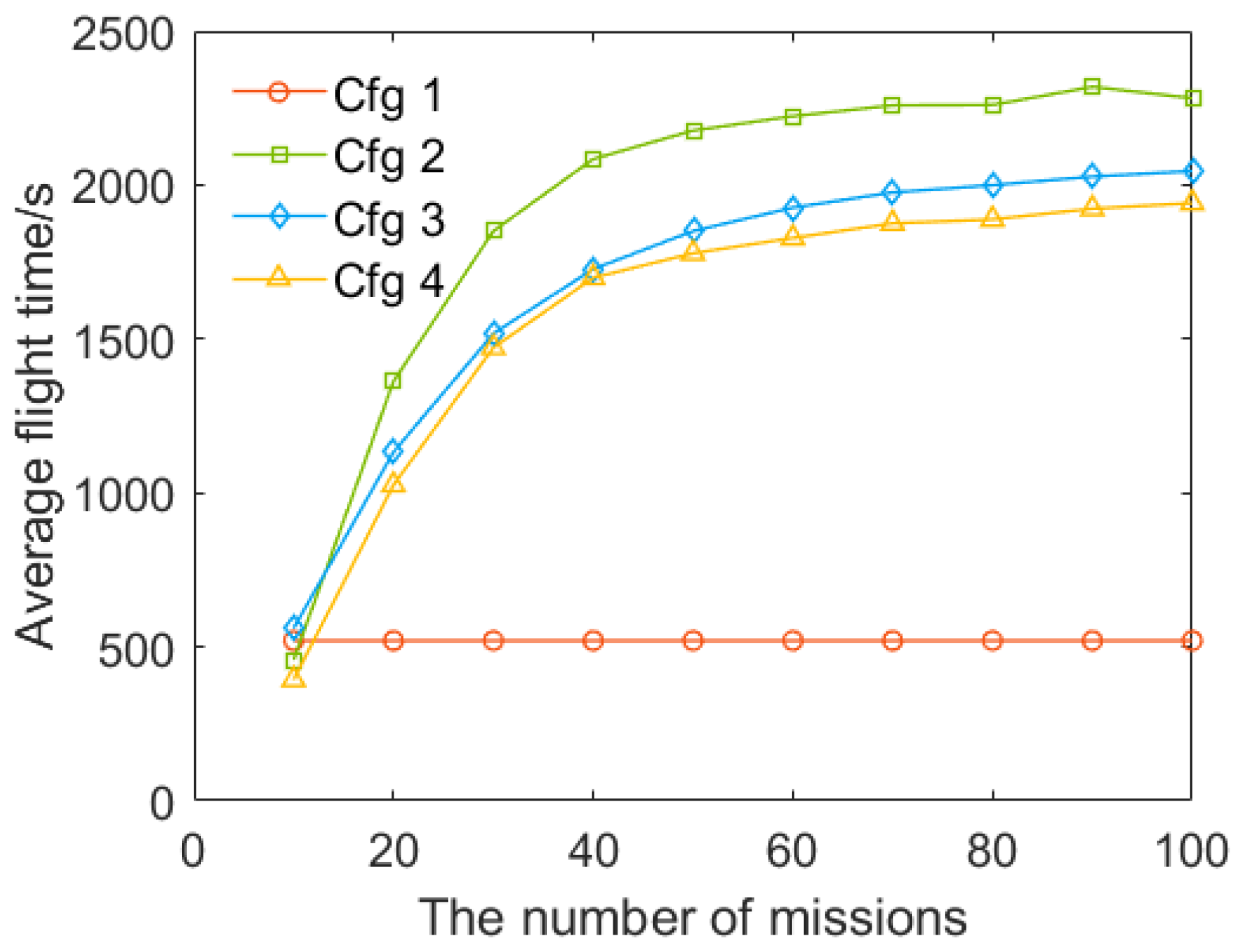
5.2. Evaluation Model Analysis
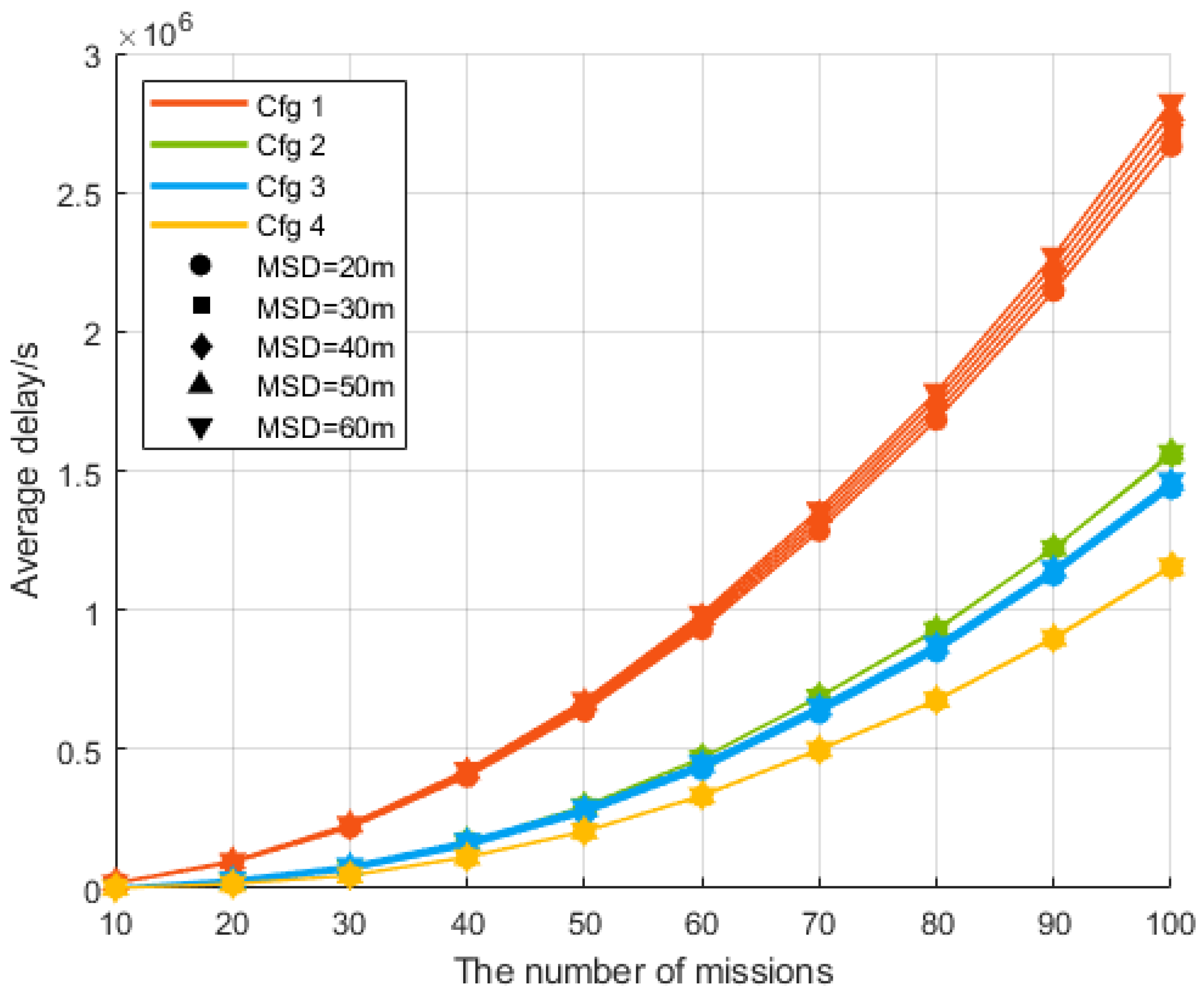
5.2.1. Average Delay
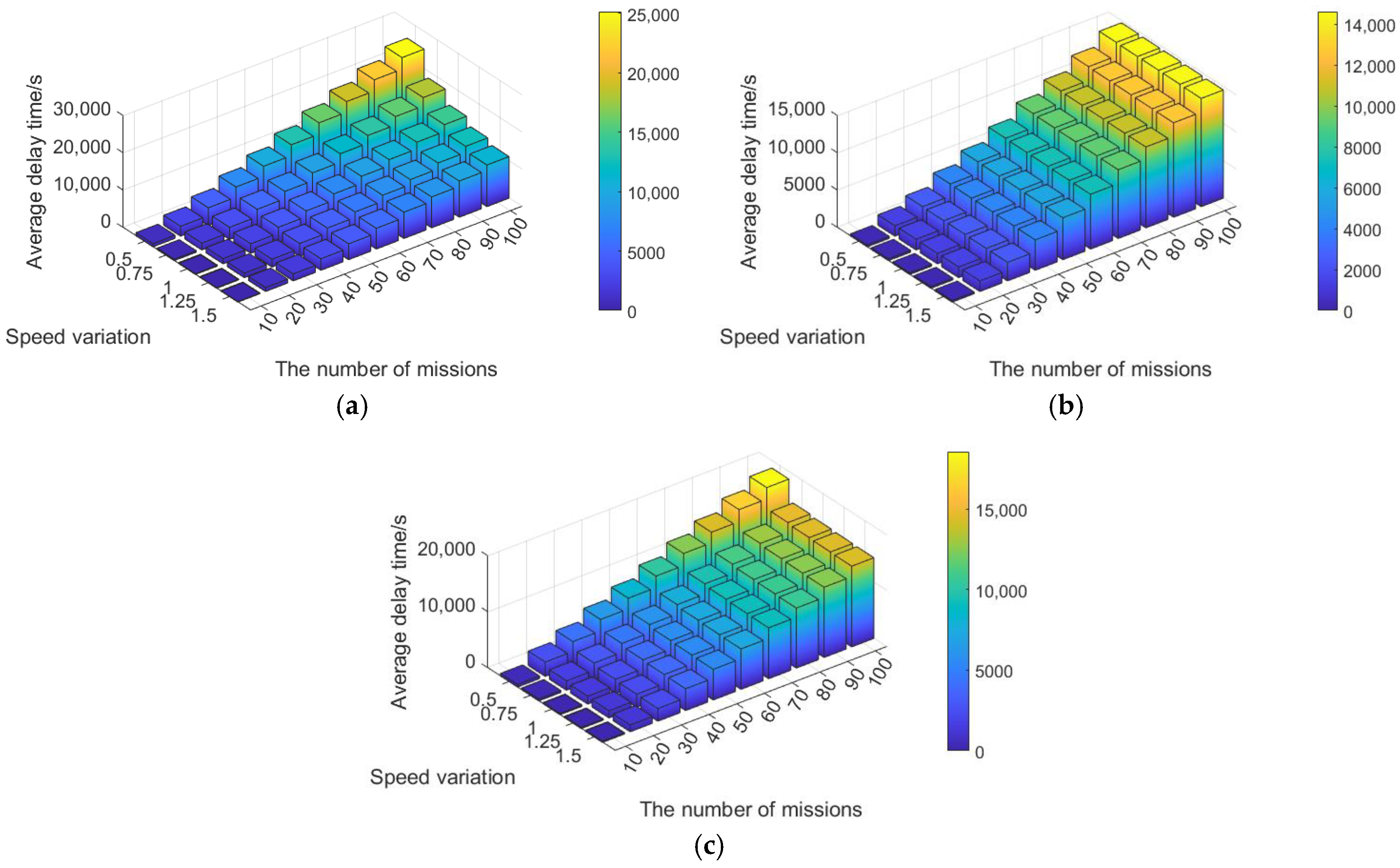
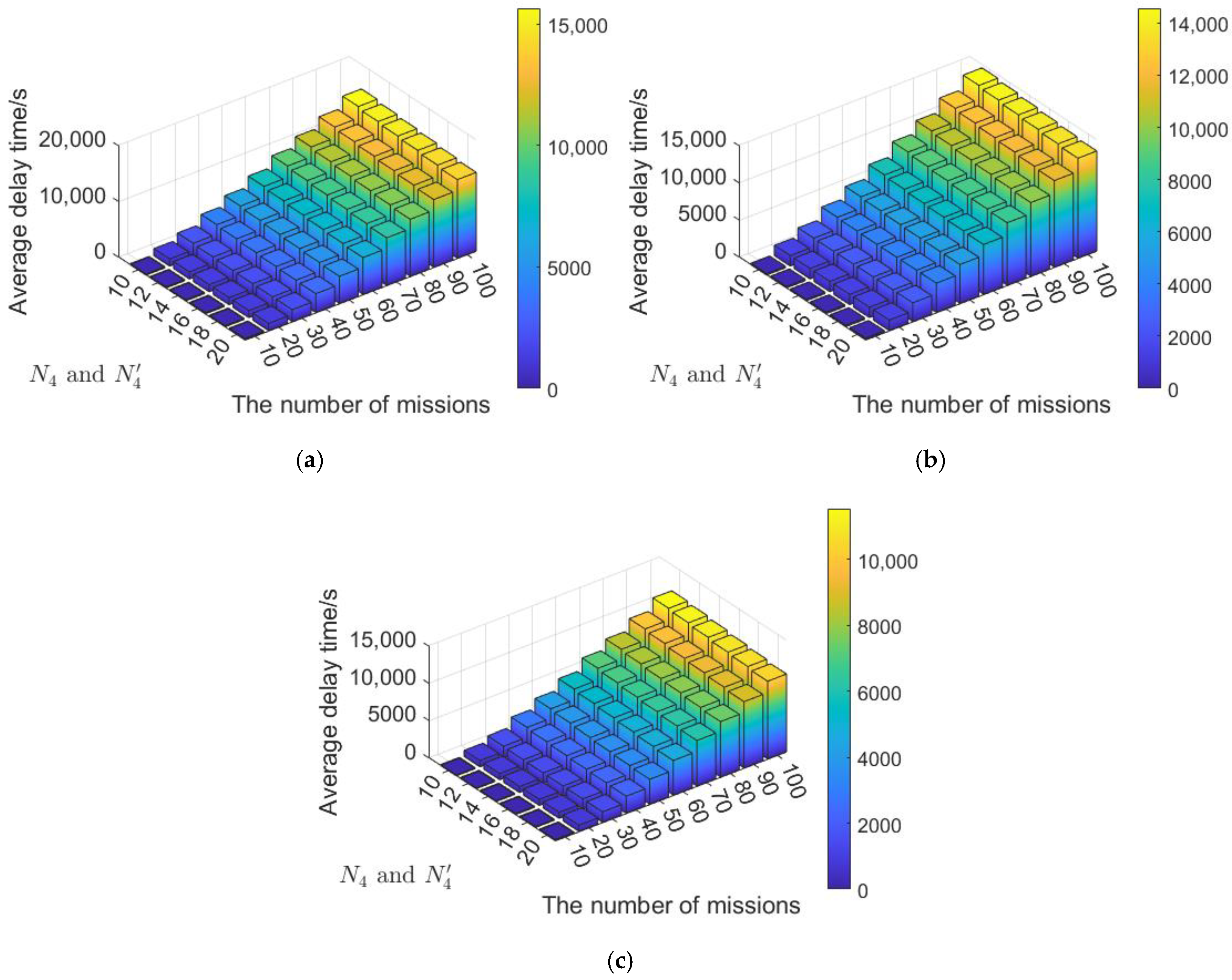
5.2.2. Sensitivity Analysis
- (1)
- Segment Speed
- (2)
- Segment Capacity
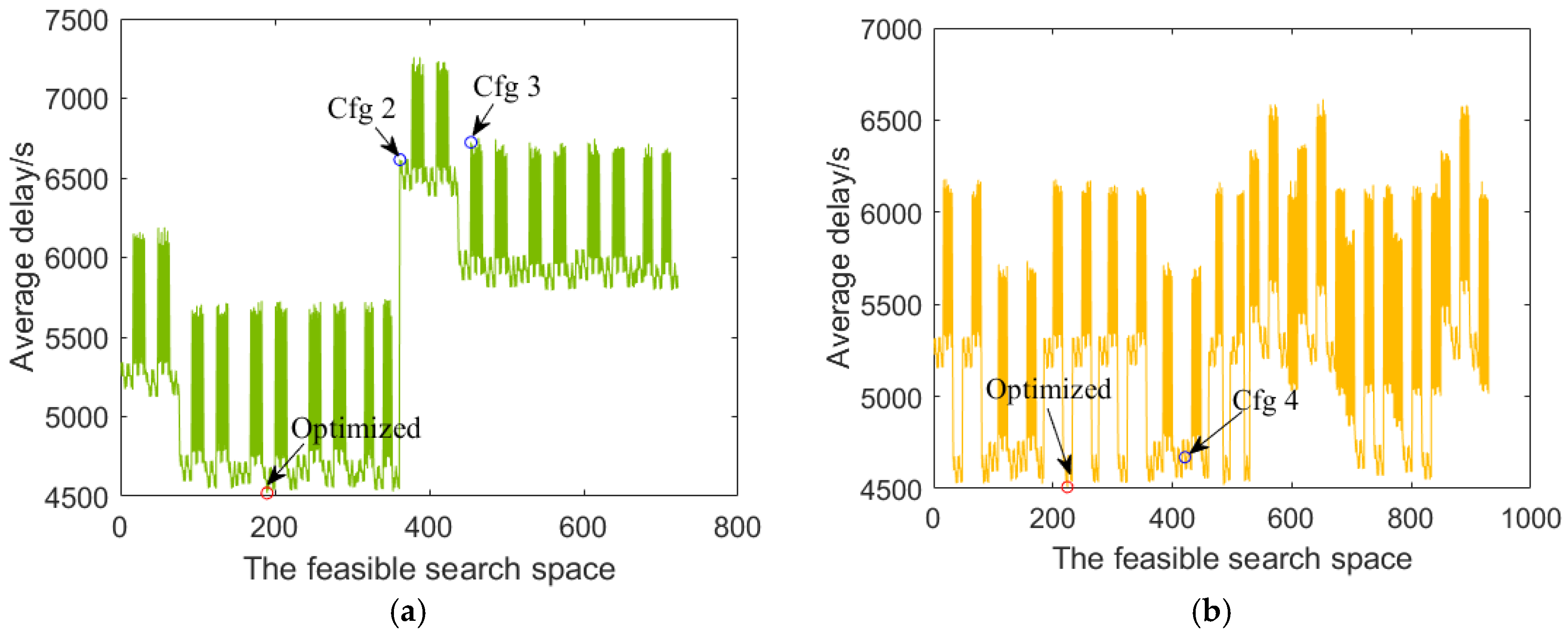
5.3. Air Routes Optimization
6. Conclusions
Author Contributions
Funding
Data Availability Statement
Acknowledgments
Conflicts of Interest
Appendix A. Design of Available Airspace for Departure and Arrival Air Routes

- (1)
- Wind field around buildings
- (2)
- Noise
- (3)
- Privacy
- (4)
- Positioning error
Appendix B. Parameter Descriptions
References
- Civil Aviation Administration of China. Route Design Specification of the Light-Small Unmanned Aircraft System for Urban Logistics. 2022. Available online: http://www.caac.gov.cn/XXGK/XXGK/BZGF/HYBZ/202208/t20220811_214939.html (accessed on 20 June 2025). (In Chinese)
- Li, J.; Kang, F.; Chen, C.; Tong, S.; Jia, Y.; Zhang, C.; Wang, Y. The improved A* algorithm for quadrotor UAVs under forest obstacle avoidance path planning. Appl. Sci. 2023, 13, 4290. [Google Scholar] [CrossRef]
- Selecký, M.; Váňa, P.; Rollo, M.; Meiser, T. Wind corrections in flight path planning. Int. J. Adv. Robot. Syst. 2013, 10, 248. [Google Scholar] [CrossRef]
- Chan, Y.Y.; Ng, K.K.; Lee, C.K.; Hsu, L.T.; Keung, K.L. Wind dynamic and energy-efficiency path planning for unmanned aerial vehicles in the lower-level airspace and urban air mobility context. Sustain. Energy Technol. Assess. 2023, 57, 103202. [Google Scholar] [CrossRef]
- Garcia, M.; Viguria, A.; Ollero, A. Dynamic graph-search algorithm for global path planning in presence of hazardous weather. J. Intell. Robot. Syst. 2013, 69, 285–295. [Google Scholar] [CrossRef]
- Wang, J.; Li, Y.; Li, R.; Chen, H.; Chu, K. Trajectory planning for UAV navigation in dynamic environments with matrix alignment Dijkstra. Soft Comput. 2022, 26, 12599–12610. [Google Scholar] [CrossRef]
- Pang, B.; Hu, X.; Dai, W.; Low, K.H. UAV path optimization with an integrated cost assessment model considering third-party risks in metropolitan environments. Reliab. Eng. Syst. Saf. 2022, 222, 108399. [Google Scholar] [CrossRef]
- Tan, Q.; Li, Y.; Wu, H.; Zhou, P.; Lo, H.K.; Zhong, S.; Zhang, X. Enhancing sustainable urban air transportation: Low-noise UAV flight planning using noise assessment simulator. Aerosp. Sci. Technol. 2024, 147, 109071. [Google Scholar] [CrossRef]
- Enayati, S.; Goeckel, D.L.; Houmansadr, A.; Pishro-Nik, H. Privacy-preserving path-planning for UAVs. In Proceedings of the 2022 International Symposium on Networks, Computers and Communications (ISNCC), Shenzhen, China, 19–22 July 2022; pp. 1–6. [Google Scholar] [CrossRef]
- He, Y.; Hou, T.; Wang, M. A new method for unmanned aerial vehicle path planning in complex environments. Sci. Rep. 2024, 14, 9257. [Google Scholar] [CrossRef]
- Dijkstra, E.W. A Note on Two Problems in Connexion with Graphs. Numer. Math. 1959, 50, 269–271. [Google Scholar] [CrossRef]
- Hart, P.E.; Nilsson, N.J.; Raphael, B. A formal basis for the heuristic determination of minimum cost paths. IEEE Trans. Syst. Sci. Cybern. 1968, 4, 100–107. [Google Scholar] [CrossRef]
- Daniel, K.; Nash, A.; Koenig, S.; Felner, A. Theta*: Any-angle path planning on grids. J. Artif. Intell. Res. 2010, 39, 533–579. [Google Scholar] [CrossRef]
- Nash, A.; Koenig, S.; Tovey, C. Lazy Theta*: Any-angle path planning and path length analysis in 3D. In Proceedings of the Twenty-Fourth AAAI Conference on Artificial Intelligence, Atlanta, GA, USA, 11–15 July 2010; pp. 147–154. [Google Scholar] [CrossRef]
- Pradeep, P.; Wei, P. Energy-efficient arrival with rta constraint for multirotor evtol in urban air mobility. J. Aerosp. Inf. Syst. 2019, 16, 263–277. [Google Scholar] [CrossRef]
- Park, J.; Kim, I.; Suk, J.; Kim, S. Trajectory optimization for takeoff and landing phase of UAM considering energy and safety. Aerosp. Sci. Technol. 2023, 140, 108489. [Google Scholar] [CrossRef]
- Song, K.; Yeo, H.; Moon, J.H. Approach control concepts and optimal vertiport airspace design for urban air mobility (UAM) operation. Int. J. Aeronaut. Space Sci. 2021, 22, 982–994. [Google Scholar] [CrossRef]
- Song, K.; Yeo, H. Development of optimal scheduling strategy and approach control model of multicopter VTOL aircraft for urban air mobility (UAM) operation. Transp. Res. Part C Emerg. Technol. 2021, 128, 103181. [Google Scholar] [CrossRef]
- Song, K. Optimal vertiport airspace and approach control strategy for urban air mobility (UAM). Sustainability 2022, 15, 437. [Google Scholar] [CrossRef]
- Lei, Y.; Qin, R.; Li, Q.; Chen, D. TLOF final approach methodology proposal utilizing dual landing pads. IET Intell. Transp. Syst. 2023, 17, 2052–2062. [Google Scholar] [CrossRef]
- Shao, Q.; Shao, M.; Lu, Y. Terminal area control rules and eVTOL adaptive scheduling model for multi-vertiport system in urban air Mobility. Transp. Res. Part C Emerg. Technol. 2021, 132, 103385. [Google Scholar] [CrossRef]
- Bauranov, A.; Rakas, J. Designing airspace for urban air mobility: A review of concepts and approaches. Prog. Aerosp. Sci. 2021, 125, 100726. [Google Scholar] [CrossRef]
- Mooney, P.; Minghini, M. A review of OpenStreetMap data. Mapp. Citiz. Sens. 2017, 37–59. [Google Scholar] [CrossRef]
- Lin, X.; Wang, C.; Wang, K.; Li, M.; Yu, X. Trajectory planning for unmanned aerial vehicles in complicated urban environments: A control network approach. Transp. Res. Part C Emerg. Technol. 2021, 128, 103120. [Google Scholar] [CrossRef]
- Wang, Y.; Wu, W. Numerical modeling of flow about several shapes of buildings. J. Univ. Shanghai Sci. Technol. 2004, 1, 19–23. (In Chinese) [Google Scholar]
- Koh, C.H.; Low, K.H.; Li, L.; Zhao, Y.; Deng, C.; Tan, S.K.; Chen, Y.; Yeap, B.C.; Li, X. Weight threshold estimation of falling UAVs (Unmanned Aerial Vehicles) based on impact energy. Transp. Res. Part C Emerg. Technol. 2018, 93, 228–255. [Google Scholar] [CrossRef]
- Intaratep, N.; Alexander, W.N.; Devenport, W.J.; Grace, S.M.; Dropkin, A. Experimental study of quadcopter acoustics and performance at static thrust conditions. In Proceedings of the 22nd AIAA/CEAS Aeroacoustics Conference, Lyon, France, 30 May–1 June 2016; p. 2873. [Google Scholar] [CrossRef]


| No. | Segment Name | Starting Point → Endpoint | Function | Design Influencing Factors | Parametric Consideration |
|---|---|---|---|---|---|
| 1 | Vertical take-off segment () | Origin vertiport () → Alignment point of the origin vertiport () | Vertical climb. | Obstacles around the vertiports, cruise altitude, etc. | Not included in parametric consideration. |
| 2 | Departure holding segment () | → Departure holding point () | Wait before entering the departure segment. | Available airspace, UAV size, number of departing UAVs, safety intervals, etc. | Categorized according to the number of UAVs accommodated, corresponding to the number of holding rings in Figure 1. |
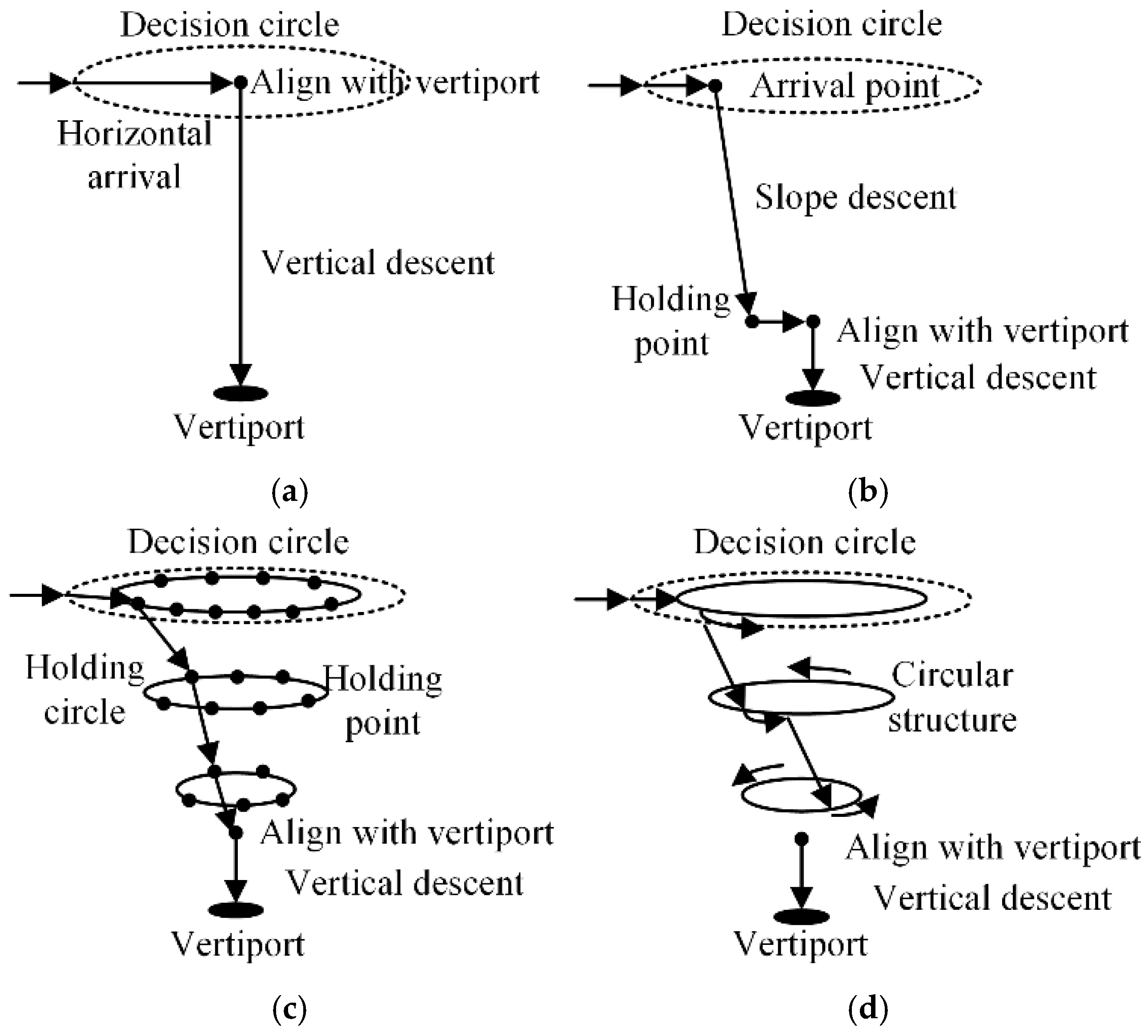
| 3 | Departure segment () | or → Departure point () | Climb and enter the en route air route. | Obstacles around the vertiports, UAV performance. | As shown in Figure 1, it can be categorized into horizontal, vertical, and slanted types. |
| 4 | Cruise segment () | → Arrival point () | Operate between vertiports. | Airspace restrictions, obstacles, electromagnetic interference, wind fields, noise, privacy, etc. | Classified based on different cruise altitudes. |
| 5 | Arrival segment () | → Arrival holding point () or alignment point of the destination vertiport () | Descend and arrive. | Obstacles around the vertiports, UAV performance, etc. | As shown in Figure 1, it can be categorized into horizontal, vertical, and slanted types. |
| 6 | Arrival holding segment () | → | Wait before landing. | Available airspace, UAV size, number of arriving UAVs, safety intervals, etc. | Categorized according to the number of UAVs accommodated, corresponding to the number of holding rings in Figure 1. |
| 7 | Vertical landing segment () | → Landing vertiport () | Align with the destination vertiport. | Obstacles around the vertiports, UAV positioning and control performance, etc. | Not included in parametric consideration. |
| Segment Index () | ) | Meaning |
|---|---|---|
| 3 | , | Departure segments’ orientation |
| 5 | , | Arrival segments’ orientation |
| 2 | , | Existence of holding segments |
| 6 | , | Existence of holding segments |
| 4 | , | Cruise segments’ altitude |
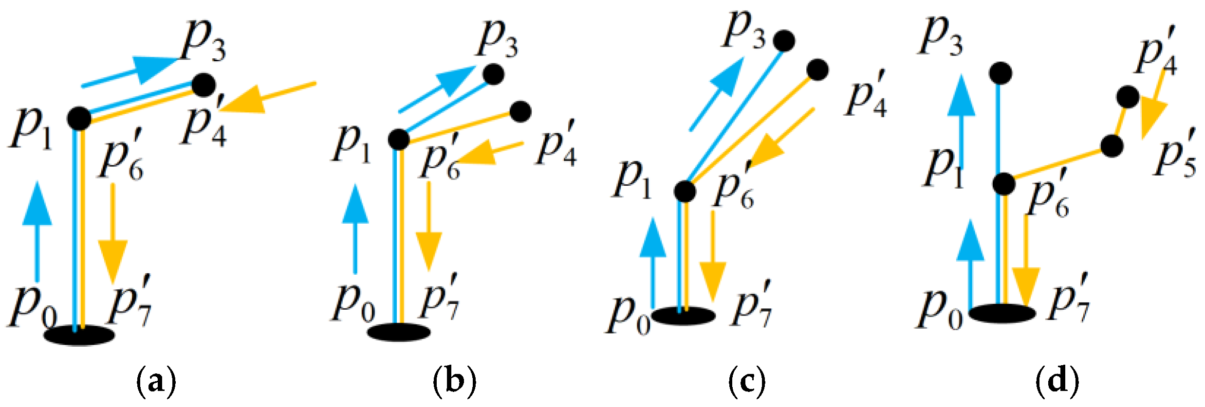
| Configuration | Characters |
|---|---|
| 1 | UAVs operate inbound and outbound flights along the same air route. |
| 2 | En route air routes are at the same altitude, operating in one direction on different routes. Departure and arrival air routes are separated. |
| 3 | En route air routes are at the same altitude, operating in one direction on different air routes. Departure and arrival air routes are separated. The speed on inclined departure and arrival air routes is significantly reduced, enhancing safety. |
| 4 | En route air routes are at different altitudes, operating in one direction on different air routes. Departure and arrival air routes are separated. |
| Parameters | Configuration 1 | Configuration 2 | Configuration 3 | Configuration 4 | |||||||||||||
|---|---|---|---|---|---|---|---|---|---|---|---|---|---|---|---|---|---|
| Segment Index () | |||||||||||||||||
| 1 | 3 | 2 | 1 | 1 | 3 | 2 | 1 | 1 | 3 | 2 | 1 | 1 | 3 | 1 | 1 | ||
| 0 | 0 | 0 | 0 | 0 | 0 | 0 | 0 | 0 | 0 | 0 | 0 | 0 | 0 | 0 | 0 | ||
| 1 | 1 | 2 | 1 | 1 | 1 | 2 | 1 | 1 | 2 | 2 | 1 | 1 | 1 | 1 | 1 | ||
| 1 | 1 | 2 | 1 | 1 | 1 | 2 | 10 | 1 | 1 | 2 | 10 | 1 | 1 | 1 | 10 | ||
| 1 | 1 | 2 | 1 | 1 | 1 | 2 | 1 | 1 | 2 | 2 | 1 | 1 | 2 | 1 | 1 | ||
| 0 | 0 | 0 | 0 | 0 | 0 | 0 | 0 | 0 | 0 | 0 | 0 | 1 | 1 | 1 | 1 | ||
| 1 | 3 | 2 | 1 | 1 | 3 | 2 | 1 | 1 | 3 | 2 | 1 | 1 | 3 | 1 | 1 | ||
Disclaimer/Publisher’s Note: The statements, opinions and data contained in all publications are solely those of the individual author(s) and contributor(s) and not of MDPI and/or the editor(s). MDPI and/or the editor(s) disclaim responsibility for any injury to people or property resulting from any ideas, methods, instructions or products referred to in the content. |
© 2025 by the authors. Licensee MDPI, Basel, Switzerland. This article is an open access article distributed under the terms and conditions of the Creative Commons Attribution (CC BY) license (https://creativecommons.org/licenses/by/4.0/).
Share and Cite
Li, Z.; Zhao, Y.; Ren, X. Parametric Modeling and Evaluation of Departure and Arrival Air Routes for Urban Logistics UAVs. Drones 2025, 9, 454. https://doi.org/10.3390/drones9070454
Li Z, Zhao Y, Ren X. Parametric Modeling and Evaluation of Departure and Arrival Air Routes for Urban Logistics UAVs. Drones. 2025; 9(7):454. https://doi.org/10.3390/drones9070454
Chicago/Turabian StyleLi, Zhongming, Yifei Zhao, and Xinhui Ren. 2025. "Parametric Modeling and Evaluation of Departure and Arrival Air Routes for Urban Logistics UAVs" Drones 9, no. 7: 454. https://doi.org/10.3390/drones9070454
APA StyleLi, Z., Zhao, Y., & Ren, X. (2025). Parametric Modeling and Evaluation of Departure and Arrival Air Routes for Urban Logistics UAVs. Drones, 9(7), 454. https://doi.org/10.3390/drones9070454