Article

MDO of Robotic Landing Gear Systems: A Hybrid Belt-Driven Compliant Mechanism for VTOL Drones Application

Department of Aerospace Engineering, Toronto Metropolitan University (Formerly Ryerson University), Toronto, ON M5B 2K3, Canada
*
Author to whom correspondence should be addressed.
Drones 2025, 9(6), 434; https://doi.org/10.3390/drones9060434
Submission received: 27 November 2024 / Revised: 30 May 2025 / Accepted: 3 June 2025 / Published: 14 June 2025

Abstract

This paper addresses inherent limitations in unmanned aerial vehicle (UAV) undercarriages hindering vertical takeoff and landing (VTOL) capabilities on uneven slopes and obstacles. Robotic landing gear (RLG) designs have been proposed to address these limitations; however, existing designs are typically limited to ground slopes of 6–15°, beyond which rollover would happen. Moreover, articulated RLG concepts come with added complexity and weight penalties due to multiple drivetrain components. Previous research has highlighted that even a minor 3-degree slope change can increase the dynamic rollover risks by 40%. Therefore, the design optimization of robotic landing gear for enhanced VTOL capabilities requires a multidisciplinary framework that integrates static analysis, dynamic simulation, and control strategies for operations on complex terrain. This paper presents a novel, hybrid, compliant, belt-driven, three-legged RLG system, supported by a multidisciplinary design optimization (MDO) methodology, aimed at achieving enhanced VTOL capabilities on uneven surfaces and moving platforms like ship decks. The proposed system design utilizes compliant mechanisms featuring a series of three-flexure hinges (3SFH), to reduce the number of articulated drivetrain components and actuators. This results in a lower system weight, improved energy efficiency, and enhanced durability, compared to earlier fully actuated, articulated, four-legged, two-jointed designs. Additionally, the compliant belt-driven actuation mitigates issues such as backlash, wear, and high maintenance, while enabling smoother torque transfer and improved vibration damping relative to earlier three-legged cable-driven four-bar link RLG systems. The use of lightweight yet strong materials—aluminum and titanium—enables the legs to bend 19 and 26.57°, respectively, without failure. An animated simulation of full-contact landing tests, performed using a proportional-derivative (PD) controller and ship deck motion input, validate the performance of the design. Simulations are performed for a VTOL UAV, with two flexible legs made of aluminum, incorporating circular flexure hinges, and a passive third one positioned at the tail. The simulation results confirm stable landings with a 2 s settling time and only 2.29° of overshoot, well within the FAA-recommended maximum roll angle of 2.9°. Compared to the single-revolute (1R) model, the implementation of the optimal 3R Pseudo-Rigid-Body Model (PRBM) further improves accuracy by achieving a maximum tip deflection error of only 1.2%. It is anticipated that the proposed hybrid design would also offer improved durability and ease of maintenance, thereby enhancing functionality and safety in comparison with existing robotic landing gear systems.

1. Introduction

Vertical takeoff and landing (VTOL) capabilities offered by rotorcraft drones have become increasingly popular, particularly in urban air mobility and other applications where maneuverability, terrain adaptability, and compact operability are critical. Unlike fixed-wing aircraft, which require long runways, VTOL systems, including rotorcraft, can land and take off in confined spaces, making them invaluable for accessing challenging environments such as mountainous terrain, forests, or maritime operations. Dynamic environments, such as ship deck landings, further amplify these challenges, with sea-induced motion, turbulent airflows, and degraded visibility creating some of the most demanding operational scenarios [1]. In rescue missions and other high-risk scenarios, advanced robotic landing gear (RLG) systems are essential for adapting to moving platforms, mitigating impact forces, and maintaining stability, even under adverse conditions. Integrating such systems into VTOL designs enables dynamic compensation for roll and pitch, as well as for uneven terrain, facilitating smoother, safer landings while reducing pilot workload and expanding operational boundaries.
Recent advancements in unmanned aerial vehicle (UAV) landing mechanisms have focused on enhancing adaptability and stability across diverse terrains. For instance, Ni et al. (2022) [2] introduced a four-legged passive cushioning design for multirotor UAVs, validated through multibody simulations to handle complex terrain conditions. Huang et al. (2022) [3] developed a lightweight vacuum-based RLG that adapts to irregular surfaces using passive mechanics. Meanwhile, Liu et al. (2022) [4] proposed an adaptive landing and aerial manipulation mechanism (ALAM) that leverages a generalized parallel architecture for flexible terrain compliance and manipulation capabilities. Additionally, recent research has explored avian-inspired aerial robotics, notably through the development of the Robotic Avian-inspired Vehicle for multiple ENvironments (RAVEN), a fixed-wing UAV with articulated legs enabling energy-efficient takeoffs, perching, walking, and hopping over obstacles. Askari et al. (2023) [5] introduced a novel underactuated claw mechanism. Building on this, Shin et al. (2024) [6] demonstrated that RAVEN’s bird-inspired multifunctional legs allow this drone to perform ground locomotion and jump-assisted takeoffs that are more energy-efficient than propeller-only launches. These developments underscore a growing emphasis on adaptability, structural optimization, and control-aware design in aerial robotics.
Despite these advances, unmanned rotorcraft face challenges when landing on uneven terrain, slopes, or in adverse weather conditions. Conventional RLG systems [7] can struggle with ground slopes of 6–15° and obstacles up to approximately 18 inches. Simulations indicate that even a slight 3-degree slope increase can raise the risk of dynamic rollover by 40%, highlighting the importance of improved ground adaptability in landing gear design [8].
To address these challenges, and expand the potential landing capabilities of rotorcraft drones, back in 2013, an Aerospace Engineering research team from Georgia Tech [9] introduced a prototype of a fully actuated four-legged RLG system with motorized joints. Building upon their conceptual research, the team developed an experimental unmanned flight vehicle in 2016, referred to as Rotorbuzz (as depicted in Figure 1), to validate the feasibility of such an RLG system [10]. This retrofitted landing gear utilizes a brake, motor, and gearbox at each joint, allowing the aircraft to conform to ground slopes exceeding 20° and navigate obstacles such as large rocks. However, the implementation of three drivetrain components per joint—totaling 24 components—led to increased weight, complexity, and maintenance demands.
To reduce weight, León et al.’s (2021) [8] proposed a three-legged RLG design using a four-bar linked mechanism actuated by a cable-driven system (Figure 2). This approach reduced weight but introduced issues such as stress concentration, pin failure, and concerns over cable alignment and long-term reliability. Simulations have highlighted the critical nature of ground slope adaptability, revealing how even a minor 3-degree slope change—from 7 to 10°—can drastically impact landing safety, with dynamic rollover risks increasing significantly. Experimentally, failures at the pin connected to the cable highlighted stress concentration issues. Although design iterations managed to center the cable on the pulley to improve performance, concerns about long-term reliability persisted.
This research builds upon existing insights by transforming four-bar conventional mechanisms (Figure 3a) into four-bar compliant or partially compliant systems (Figure 3b), which eliminate unnecessary drivetrain components while improving overall adaptability. A four-bar linkage or parallel mechanism stands as a reliable mechanism capable of efficiently transferring input motion in parallel directions. Such mechanisms are particularly relevant to the design of RLG for VTOLs, including cable-driven systems (Figure 3a), making the RLG more impact-resistant [11]. It is anticipated that using compliant or flexible links, instead of traditional rigid links and pin joints, will lead to a better RLG system for VTOL drone applications, with improved durability and reduced maintenance issues related to wear, lubrication, backlash, weight, and noise.
Compliant mechanisms inherently provide flexibility, functioning as both springs and dampers, thereby removing the need for separate components. While flexible links offer certain advantages, circular flexure hinges (CFHs) hold significant potential due to their predictable mechanical behavior, enhanced fatigue resistance, and precise motion control. However, achieving these benefits requires the accurate modeling of flexure hinges, a challenge that remains underexplored. This research addresses that gap by applying a new general empirical equation for CFH rotational stiffness and compliance, previously proposed by the author in [12], enabling reliable modeling, prediction, and control for adaptive dynamic applications.
Furthermore, a novel belt-driven actuation system is proposed to overcome the limitations of cable-driven designs. By increasing the contact area between the timing belt and the toothed pulley, this approach improves torque transfer, reduces stress concentration, and enhances motion control. The resulting hybrid belt-driven compliant mechanism approach demonstrates versatility, with potential applications beyond landing gear, such as in soft grippers, legged robotics, and morphing aircraft wings, emphasizing their value in dynamic systems.
In summary, the key innovations of this work include the following:
  • Development of a Reliability-Based Design Optimization (RBDO) framework integrating sensitivity analysis for robust compliant RLG designs.
  • Introduction of a flexible dynamics model of a VTOL with compliant legs using the floating frame of reference formulation (FFRF).
  • Formulation of a flexible multibody dynamic simulation framework for four-bar compliant mechanisms in landing scenarios.
  • Implementation of a new empirical equation for CFH rotational stiffness/compliance, validated for design accuracy.
  • Optimal geometry determination for a three-series flexure hinge (3SFH) system tailored to RLG applications.
  • Proposal and integration of a four-bar belt-driven actuation system to reduce weight and increase torque transfer.
  • Application-specific developments including material performance validation (Ti-13 and Al-7075) and the design of optimized compliant RLG systems for VTOL capabilities.
These contributions collectively advance both the theoretical modeling and practical implementation of adaptive, lightweight, and reliable robotic landing gear systems suitable for VTOL drones operating in dynamic and unpredictable environments.

2. Literature Review

This section presents a brief survey of some of the publications available in the open literature on the topics of unmanned aerial vehicles (UAVs) with flexible landing gear and robotic landing gear (RLG). Vertical takeoff and landing (VTOL) capabilities are crucial for a wide range of applications such as surveillance, search and rescue operations, and package delivery, where several advantages can be achieved by incorporating compliant mechanisms into the design of RLG. These advantages include enhanced shock absorption, stability, and adaptability to uneven terrain and obstacles. Compliant mechanisms, also referred to as flexible or elastic mechanisms, can bend and flex under load. This also allows them to absorb impacts and vibrations which, in turn, can reduce the risk of structural damage. Additionally, if incorporated into the robotic landing gear (RLG) [7,9], compliant mechanisms can improve the system stability during landing and takeoff by providing a larger contact area with the ground.
To optimize such systems, multidisciplinary design optimization (MDO) methodologies can be used to design lightweight retractable landing gears. Ryu et al. [13] proposed a gradient-based multidisciplinary design optimization (MDO) methodology to design lightweight retractable landing gear with locking links, accounting for actuator performance and out-of-plane load cases. Their approach utilized a modified input–output equation for multibody kinematics, achieving both structural and kinematic optimization. Building on this, Li et al. [14] employed a combination of spatial bistability and a graph search approach to optimize landing structures, enhancing shock absorption and ensuring the successful landing of UAVs under various conditions. Further advancements in RLG systems include the application of mechatronics approaches, as shown by [15], which enhanced the stability, safety, and adaptability of landing gear systems for drone applications. Similarly, Das et al. [16] highlighted the role of compliant mechanisms in enabling the landing gear of UAVs to adapt dynamically to various terrains by adjusting their shape and stiffness. These innovations improve performance and safety in challenging environments.
Building on these innovations, Liang et al. [17] addressed the pivotal role of landing gear in ensuring the safe takeoff and landing of unmanned aerial vehicles (UAVs), a critical consideration as their applications continue to diversify. The paper emphasizes the importance of lightweight and high-strength landing gears, especially with the increasing value of cargo and UAVs themselves. Recognizing the potential of composite materials in meeting these requirements, the study presents a comprehensive exploration of the design, numerical analysis using Ansys, manufacturing process, and experimental verification using LabVIEW for composite landing gear designed and made from carbon fiber-reinforced polymer (CFRP), specifically for a UAV. By integrating numerical analysis and experimental validation, the study provides a holistic understanding of the performance of the composite landing gear. This research contributes significantly to the field by showcasing the potential of composite materials in UAV landing gear design and offering insights into the influence of carbon fiber orientations on the gear’s structural characteristics. The integration of numerical simulations and experimental results enhances the credibility of the findings, making the paper a valuable reference for those involved in UAV technology, structural design, and composite materials research.
Manivannan et al. [9] were the first to pioneer work on robotic landing gear (RLG) systems, introducing a four-legged, two-jointed configuration with all joints actuated. This articulated design significantly enhanced the degrees of freedom available for landing on irregular or sloped terrains, a notable limitation of conventional rotorcraft landing gear. By allowing the landing gear to dynamically conform to uneven surfaces, this innovation reduced reliance on rotor thrust magnitude and direction, enabling quicker and safer landings in challenging environments. Their study employed a multibody simulation tool designed to analyze the dynamics of rotorcraft equipped with RLG, encompassing overall system motion, load computation, and stress analysis. Through dynamic simulation and analysis, Manivannan et al. [9] demonstrated that a robotic four-legged, landing gear system can significantly expand the range of slopes and types of terrain suitable for landing. This research offered valuable insights into the potential benefits of RLG, paving the way for enhanced rotorcraft versatility and adaptability in challenging and remote environments.
Building upon the design by Manivannan et al. [9], in a recent research study, Kim et al. [18] added a locking mechanism to the UAV’s four-legged landing system and, through a comprehensive multibody dynamic simulation, they demonstrated that its addition effectively eliminates landing failures, emphasizing the importance of flexure hinges versus traditional joints. In addition, by incorporating locking mechanisms on the RLG feet, landing gear slip and bounce can be eliminated during landing events [18] (the rotorcraft and RLG rigid bodies are depicted in Figure 4).
Kim et al.’s paper [18] addresses the critical issue of improving the performance of robotic landing gear (RLG) for UAV rotorcraft, particularly in challenging landing scenarios such as sloped uneven terrain, unprepared areas, and ship decks. The paper emphasizes the significance of the interaction between the RLG feet and the landing surface, highlighting that slipping or bouncing can lead to failed landings and catastrophic accidents. As also indicated earlier in this paper, the proposed solution involves the implementation of locking mechanisms on the RLG feet to prevent slip and bounce during landing events. Through a comprehensive MBD simulation, the paper demonstrates that the use of locking mechanisms effectively eliminates landing failures that may occur with non-locking landing gear configurations. The study acknowledges a moderate increase in landing gear loads as a trade-off for enhanced stability. Importantly, the results indicate that even in situations where some foot-locking mechanisms are inoperable or break away, landing event failures can still be avoided. Additionally, the implementation of foot-locking mechanisms offers the potential to reduce or eliminate the need for active control of the RLG’s legs. Overall, the findings of this paper provide valuable guidance for the development of integrated RLG systems with locking mechanisms, contributing to the enhancement of safety and reliability in rotorcraft landings under various challenging conditions.
The research paper by Kiefer et al. [19] addressed the critical issue of mitigating hard landings in UAV rotorcraft through the implementation of a robotic legged landing gear (RLLG) system. Rotorcraft’s flexibility in aircraft-to-ground interfacing is acknowledged as a unique and beneficial feature, but hard landings can still occur due to unintended descent rates, potentially leading to damage, structural failure, or injuries. The proposed RLLG system acts as a shock absorber with a substantial stroke, allowing the aircraft to decelerate over a larger distance compared to traditional landing gear systems, thereby softening the impact of hard landings. The study utilizes a comprehensive multibody dynamics (MBD) simulation tool to explore the efficacy of RLLG in reducing loads during hard landings for various landing configurations. The results demonstrate a significant reduction in peak loads, ranging from 70% to 90%, depending on the specific landing conditions, when RLLG is employed instead of conventional landing gear. Additionally, Monte Carlo simulations are used to validate the robust performance of the RLG system under uncertain conditions. This research showcases the potential of RLLG as a robust solution to enhance the safety of rotorcraft operations, particularly in scenarios where hard landings are a concern.
León et al. [7] were the first to introduce a three-legged, robotic landing gear (RLG) system for unmanned rotorcraft, consisting of two cable-actuated legs and one unactuated rear (tail) leg, all employing a four-bar linkage design. While the four-bar mechanism inherently limits motion to a differential mode, this design trade-off was purposefully selected to minimize the RLG’s total weight, integrate the entire actuation system within the existing helicopter structure, and enable landings on significantly sloped or uneven surfaces. This configuration successfully performed ground and flight tests, demonstrating the feasibility of simplifying the actuation system compared to four-legged designs. By reducing the number of motors required— from eight to just one or two— this innovative approach achieved significant weight savings while maintaining performance. Later, León et al. [2] reported that the RLG system adds 14 kg to the aircraft’s dry mass of 122 kg, amounting to 28% of the maximum payload weight and achieving a 44% weight improvement compared to the four-legged RLG design (refer to the S-100 Camcopter depicted in Figure 5).
León et al. [8] investigated the enhancement of unmanned rotorcraft landing capabilities on sloped and rough terrain through closed-loop feedback control of the robotic landing gear (RLG). The study specifically addressed the limitations of modern RLG systems when landing on dynamic platforms due to the absence of fuselage roll and roll-rate feedback in their controllers. León et al.’s simulations [8] further highlighted the critical nature of ground slope adaptability, revealing that even a minor 3-degree slope change—from 7 to 10°—can drastically affect landing safety, with dynamic rollover risks increasing significantly. The introduced crashworthy cable-driven system was designed and implemented on the commercial Multi-Role, Helicopter, UAV Platform, S-100 Camcopter [20], demonstrating its ability to expand static landing zone limits threefold and facilitate dynamic platform landings in rough sea state conditions. A novel roll and foot-force feedback fused control algorithm was developed to enable ship deck landings without requiring deck lock or advanced vision-based landing systems. MBD simulations showcased the advantages of this integrated roll and force feedback approach, with experimental dynamic landings on moving platforms and simulated sea states providing practical validation. The paper not only explored the usability of the RLG through ground experimentation, but also presented simulations of the S-100 Camcopter [20] landings under more challenging conditions, contributing valuable insights into how the newly proposed controller mitigates dynamic rollover risks. This work significantly advances the field of RLG technology, particularly in the context of dynamic platform landings, providing a robust and crashworthy solution with broad implications for rotorcraft operations in challenging environments.
Di Leo et al. [7] introduced two innovative technologies aimed at advancing the capabilities of robotic landing gear for unmanned rotorcraft. Their first technology presents a novel cable-driven four-bar link mechanism designed specifically for rotorcraft robotic landing gear. The paper emphasizes the advantages of employing two such four-bar linkages that share a common driving cable within a vehicle. The study includes detailed insights into kinematics and static force distributions, demonstrating that for UAVs in the weight class of 200 to 400 lbs, the leg mechanism can effectively conform to ground slopes of approximately 20°. Moreover, static load distribution analysis reveals a significant reduction in net loads experienced by the actuator compared to traditional actuation strategies. Their second technology focuses on comprehensive design, manufacturing, and drop testing workflows for the rapid iteration of robotic landing gear. The workflow encompasses design, simulation, rapid manufacturing, and crash-survivability testing, achieving a two-week turnaround time for a complete design iteration. The paper demonstrates the utilization of 3D-printed acrylonitrile-butadiene-styrene (ABS) mandrels to produce fully functional carbon fiber-reinforced polymer (CFRP) components, revealing the feasibility of rapid manufacturing. The study concludes by highlighting the effectiveness of the design workflow and the structural survivability characteristics of the cable-driven four-bar link mechanism, validated through a series of ever-improving design iterations. This research significantly contributes to the development of more capable and resilient robotic landing gear for rotorcraft applications.
The above-presented literature review revealed the challenges faced by fixed and robotic landing gear (RLG) systems for unmanned rotorcraft applications, and the advantages of the latter. To the best of the authors’ knowledge, there is no publication in the open literature reporting any existing VTOL UAV landing systems using compliant mechanisms. Therefore, building upon these insights, this paper seeks to enhance the understanding of compliant mechanisms and focuses on exploring the potential of compliant mechanisms’ integration in the RLG designs, as a hybrid solution to address their shortcomings, as well as their optimization for vertical takeoff and landing (VTOL) UAV applications. The primary objective is to address the inherent limitations faced by unmanned rotorcraft during VTOL operations, particularly on uneven slopes and unpredictable terrains. By leveraging methodologies such as flexible multibody dynamics (FMD), the presented research aims to enable more accurate predictions and optimized RLG designs, while considering the applied moment at the tip of the flexible legs. It is anticipated that the proposed hybrid RLG system would present a robust and efficient solution that dynamically adapts to various environmental conditions, ensuring the enhanced safety and performance of VTOL UAVs.

3. Existing RLG vs. Proposed Design

In the present study, a novel hybrid design for a robotic landing gear mechanism for VTOL UAVs is introduced, focusing on replacing the traditional pin-joint mechanism with a compliant mechanism, and using a belt-driven system instead of the current cable-driven actuation system for the three-legged VTOL UAV RLG system. Figure 6 illustrates a comparison between the existing RLG systems and the proposed three-legged, belt-driven compliant mechanism, highlighting the advancements achieved in this research.
As discussed in the Introduction Section, previous four-legged, all-joints-actuated designs for robotic landing gear (RLG) systems [9,10,18,21] presented certain limitations. The findings of this study demonstrate that a three-legged RLG design with a belt-driven compliant four-bar link mechanism offers valuable advantages in VTOL capabilities compared to earlier designs, such as the actively controlled, articulated four-legged, two-jointed system, where all joints are actuated. Unlike the complex actuated joint approach, the compliant mechanism simplifies the system by reducing the number of active components, thereby lowering the overall weight and improving energy efficiency while maintaining essential structural flexibility.
When compared to the three-legged, cable-driven four-bar link mechanism [7,8,11,20,22], the belt-driven system also provides superior stability and performance in complex landing scenarios due to reduced vibration and increased torque transfer capabilities. These improvements result in more effective load distribution at the end of the legs, which is critical during landings on uneven terrain. This novel design advances precision in compliant mechanism configurations, offering enhanced durability and ease of maintenance, thus improving functionality and safety for robotic landing gear systems beyond what was achievable with earlier cable-driven models.
As also emphasized by León et al. [18], there is a significant dynamic interaction between the RLG feet and the landing surface, which becomes particularly evident during flight tests. For instance, the cable-driven design experienced a destabilizing pitching moment at landing. In contrast, a three-legged VTOL UAV design equipped, with belt-driven, four-bar compliant mechanism, front legs (Figure 7), would better distribute the forces across the system, minimizing the destabilizing effects of uneven landings and thereby improving overall landing stability. This design can also be extended to a four-legged configuration, utilizing two parallel compliant four-bar mechanisms to provide greater control and support for heavier vehicles.
Moreover, the belt-driven four-bar compliant mechanism is highly effective at controlling pitch movements, particularly in uneven landings. By employing a three-legged configuration, where both legs are actuated by a single belt-driven system, the pitching moment observed in the design during single-point landings is effectively mitigated. This allows for precise control of the VTOL’s (e.g., rotorcraft) attitude, with landing forces evenly distributed between the two actuated legs, resulting in an improved landing performance and reduced risk of instability.
The redesign originates from an unmanned rotorcraft with cable-driven robotic landing gear by the Georgia Tech team, as illustrated in a study conducted by León et al. (2021) [11]. Figure 8a,b present the schematics of the mechanism on even and uneven ground, highlighting key components and dimensions. This concept integrates a continuous cable, springs, and a spool connected to an electric rotary actuator. While the cable-driven system offers some benefits, such as acting as a fuse to prevent other structural failures, it also has challenges due to the smaller contact area compared to a belt–pulley system. This limitation led to redesign efforts to prevent failures like the pin (upper-right) in Figure 8c shearing the leg’s metal hard point entirely, resulting in a loss of structural integrity. This failure occurs because the cable routes about a point not centered at that joint, requiring perfect routing to avoid large bending/shear loads, making the design expensive and unsafe. Replacing the cable-driven system with a belt-driven one addresses these issues. The belt-driven system, with its larger contact area and larger pulley diameter compared to spools, distributes the load more evenly, centers the rotation, and increases the control. The use of a timing belt also allows for higher torque and reduces the risk of slippage.
In the design presented by León et al. [11], the symmetric neutral position of the legs in Figure 8c normally stands the legs upward. Retracting the cable achieves the horizontal level in Figure 8d but requires double rotation to reach the configuration shown in Figure 8e. Subsequent iterations explored adding a compression spring in parallel with the cable, connecting the lower-left and upper-right corners to drive upward motion. However, this dual spring or double rotation mechanism was energy-consuming and unsafe. To address these issues, the novel hybrid compliant four-bar mechanism introduced here facilitates both upward and downward motion using the moment at the tip of each flexible leg. This design, with half the rotational distance, ensures safety and energy efficiency during landing. By partially replacing the traditional pin-joint mechanism with the compliant mechanism using flexure hinges, the need for additional springs is eliminated, resulting in a more streamlined design. In addition, the compliant mechanism allows for efficient and reliable operation of the robotic landing gear, facilitating smooth and controlled motions. The incorporation of belt-driven actuation, coupled with the compliant mechanism, could further enhance flexibility, durability, and maintenance simplicity, presenting a promising alternative for improving the performance of robotic landing gear systems. An illustrative design example of the proposed hybrid belt-driven compliant mechanism for a 2D VTOL UAV landing system is presented in Figure 9, using (a) flexible links or beams and (b) flexure-hinges. It is worth noting that this system represents the front part of the three-legged RLG system, but it could be readily extended to a full 3D (four-legged) landing system.
In short, the design optimization of robotic landing gear for enhanced VTOL capabilities requires a holistic Reliability-Based Design Optimization (RBDO) framework based on sensitivity analysis. This framework integrates key aspects such as static analysis, system design, dynamic modeling, and control strategies to improve reliability and performance while considering parameter uncertainties. By combining reliability analysis with optimization techniques, RBDO establishes a multidisciplinary design optimization (MDO) foundation, depicted in the design structure matrix (DSM) of the RBDO architecture for compliant RLG (Figure 10). The RBDO framework further leverages flexible multibody dynamics to predict and enhance the dynamic performance of robotic systems across configurations, optimizes actuation design selection, and ensures robustness across the full operational range of the robot’s workspace [22,23]. This approach not only supports consistent performance through optimized actuation design but also enhances system stability, reliability, and safety, optimizing the RLG system for VTOL capabilities, particularly in response to uneven terrains and complex landing conditions. The following Methodology Section of this paper will delve into these aspects in detail. The aim is to explore the potential of compliant mechanisms as a solution to enhance the parameterization design of dynamics systems using compliant mechanisms by reducing errors in the design process. It is worth noting that certain aspects are beyond the scope of this paper and will not be covered here. These include hard landing scenarios, detailed contact modeling, and locking mechanisms, as well as the modeling of six degrees of freedom (6DOF) rigid body dynamics, which would require separate analysis and are not addressed here. The focus is rather on achieving an optimized and efficient RLG design for standard landing settings.

4. Methodology

In what follows, the methodology used in this study is briefly sketched out. First, the static analysis and system design (Section 4.1) will be explored, outlining how compliant mechanisms and flexure hinges are incorporated to ensure structural efficiency (Section 4.1). The Static Analysis and System Design Section compares the new belt-driven actuation system with previous cable-driven approaches, focusing on the improved load handling and reliability achieved using flexure hinges. This comparison is crucial for understanding the mechanical advantages offered by the new design in terms of weight reduction and improved operational efficiency.
The Simulation and Testing Section (Section 4.2) evaluates the system’s performance under static loads and high-impact conditions, particularly analyzing failure modes in the four-bar mechanism during hard landings. This evaluation is essential for identifying potential weaknesses in the design and ensuring the system’s robustness. Simulation tests will be used to validate the system’s performance under realistic conditions.
The flexible rotorcraft modeling is based on the floating frame of reference formulation (FFRF) and generalized coordinates, which enables accurate dynamic simulations by considering both rigid and flexible components, essential for ensuring stability and control during landing [24]. Unlike traditional rigid body dynamics, where components like landing gears are treated as entirely rigid, the FFRF method captures the flexibility of these components, allowing for a more realistic representation of bending deformations. This flexibility is vital for analyzing interactions between the helicopter’s landing gear and uneven terrains, further contributing to stability during landing. An in-depth discussion on the FFRF (Section 4.3) will be followed by the Dynamics Modeling and Equations of Motion of the helicopter’s flexible landing gear. This elaborates on the derivation of the governing equations, which account for the complexities of both rigid body motion and local deformations of flexible elements. The subsequent Control Strategy Section 4.4 discusses the implementation of proportional and derivative controllers, focusing on achieving optimal stabilization during landing maneuvers, which the FFRF approach also integrates seamlessly with the system’s control strategy, particularly in relation to roll angle adjustments and overall dynamic stability.
The Pseudo-Rigid-Body (PRB) model will be introduced (Section 4.5) to approximate the behavior of compliant mechanisms, while crash-survivability is addressed through resistance and actuation calculations (Section 4.6). These two sections outline how the PRB model is utilized to simplify the analysis of compliant mechanisms, providing insights into the behavior of flexure hinges under dynamic loading conditions. The Resistance and Actuation Calculations for Crash-Survivability Section (Section 4.6) addresses the critical considerations for ensuring that the landing gear can withstand impact forces while maintaining functionality.
The Compliant Mechanism: Design Optimization Section (Section 4.7) delves into the optimization techniques employed to enhance the performance of the landing gear system. The design optimization of compliant mechanisms, specifically the optimal three-series flexure hinges (3-SFH) using the PRB model (Section 4.8), concludes with the methodological approach, emphasizing how these design choices enhance both functionality and safety. These integrated approaches are explored further in the results and discussion, where the design and performance of the flexible RLG system are evaluated in detail (Section 5).
While this methodology provides a robust framework for modeling and controlling the helicopter’s landing gear system, as also mentioned earlier in the previous section, certain aspects, such as hard landing scenarios, contact modeling, and locking mechanisms for post-landing stabilization, are beyond the scope of this paper and are omitted here.

4.1. Static Analysis and System Design

Initial searches in the related literature databases performed by the authors led to examples that focused more on the dynamic aspects of the analysis. However, in landing gear design, static loading is also a highly important loading scenario to consider. Therefore, one should also consider the flexibility of the landing gear frame and components, the landing gear-ground interaction, and the related friction. 
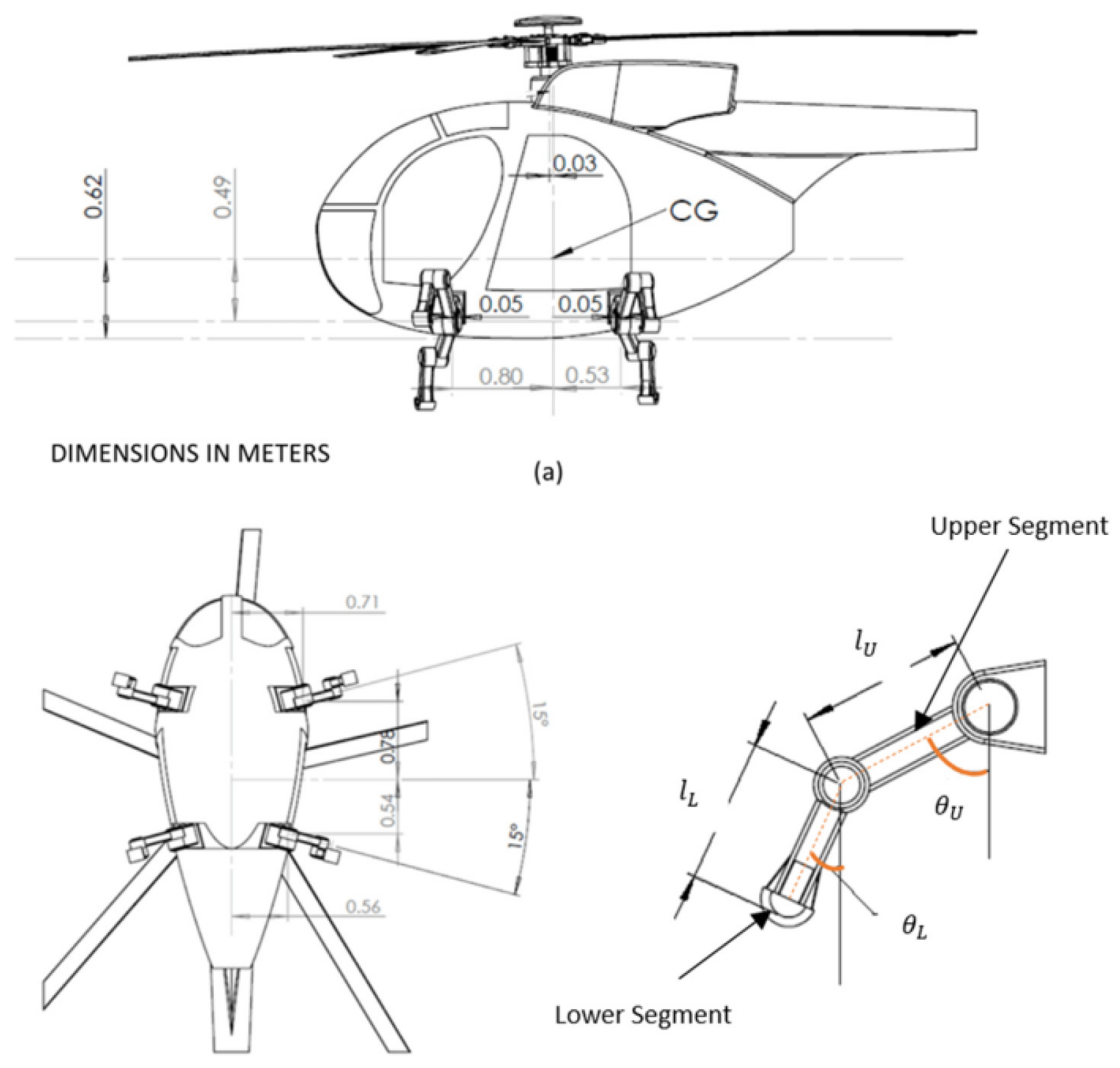
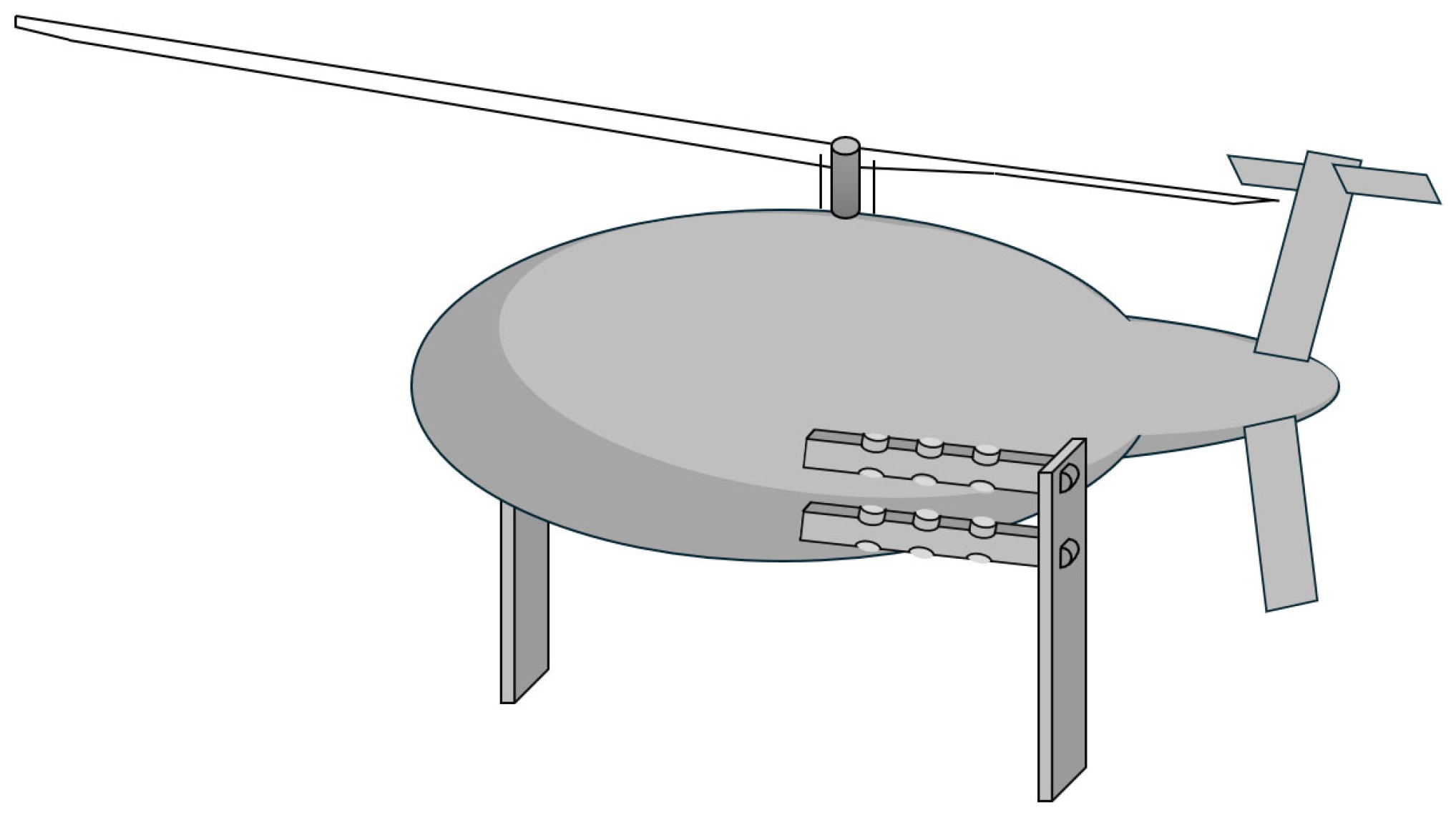
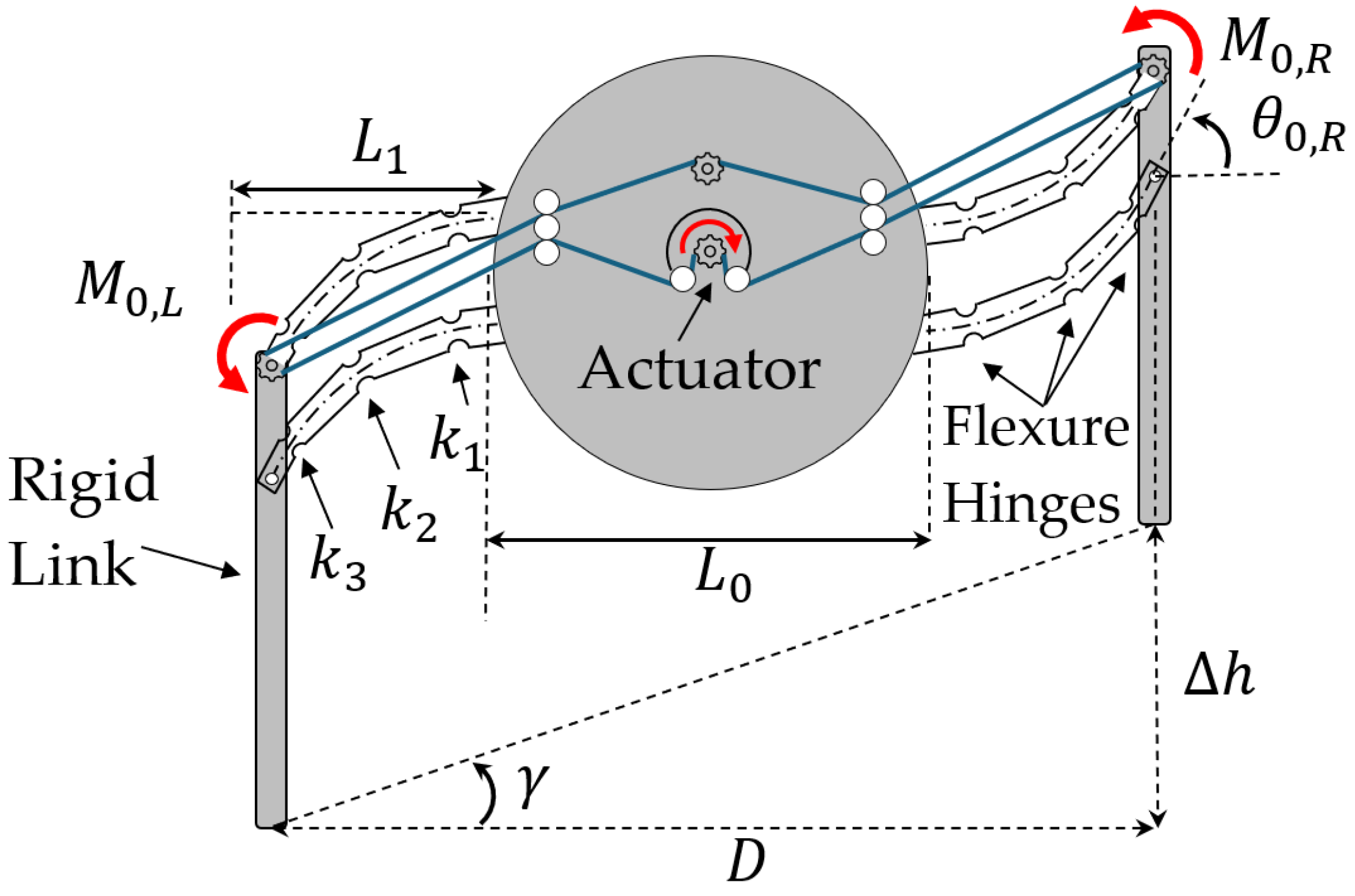
Figure 11 schematically presents an illustrative example of the proposed 2D hybrid RLG design, and its free body diagram (FBD), incorporating two flexible/compliant mechanisms, flexure hinges, and belt-driven actuation. The middle part, representing the fuselage, is a rigid cylinder with a radius of a f u s , and the distance between two legs, or the diameter, is L 0 = 2 a f u s . Each leg consists of a rigid link and two flexible links, which are modeled as identical Euler–Bernoulli beams of length L 1 , constant bending stiffness E I , and a cross-sectional area A . Additionally, the flexible links have a perpendicular distance L 2 between them.
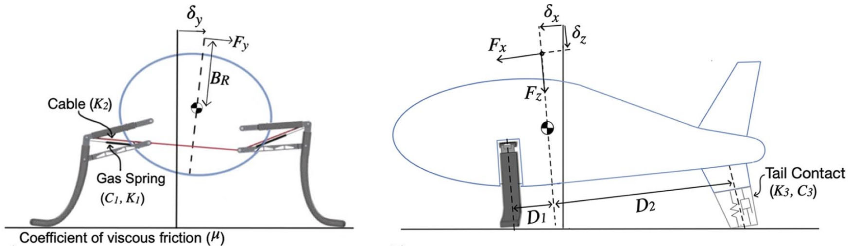
The compliant mechanism presented also has some unique benefits in terms of how loads are distributed across the structure and onto the actuator; a simple static analysis based entirely on static force balances across the structure. Consider first the free body diagram (FBD) of the geometry shown in Figure 11, where the weight, W , is balanced by two vertical loads, V 1 and V 2 , computed from a sum of forces and moments about the center of the fuselage, V 1 = V 2 = W 2 . One notes that the moment arm for V 1 and V 2 with respect to the center of the fuselage varies slightly as the slope angle changes.
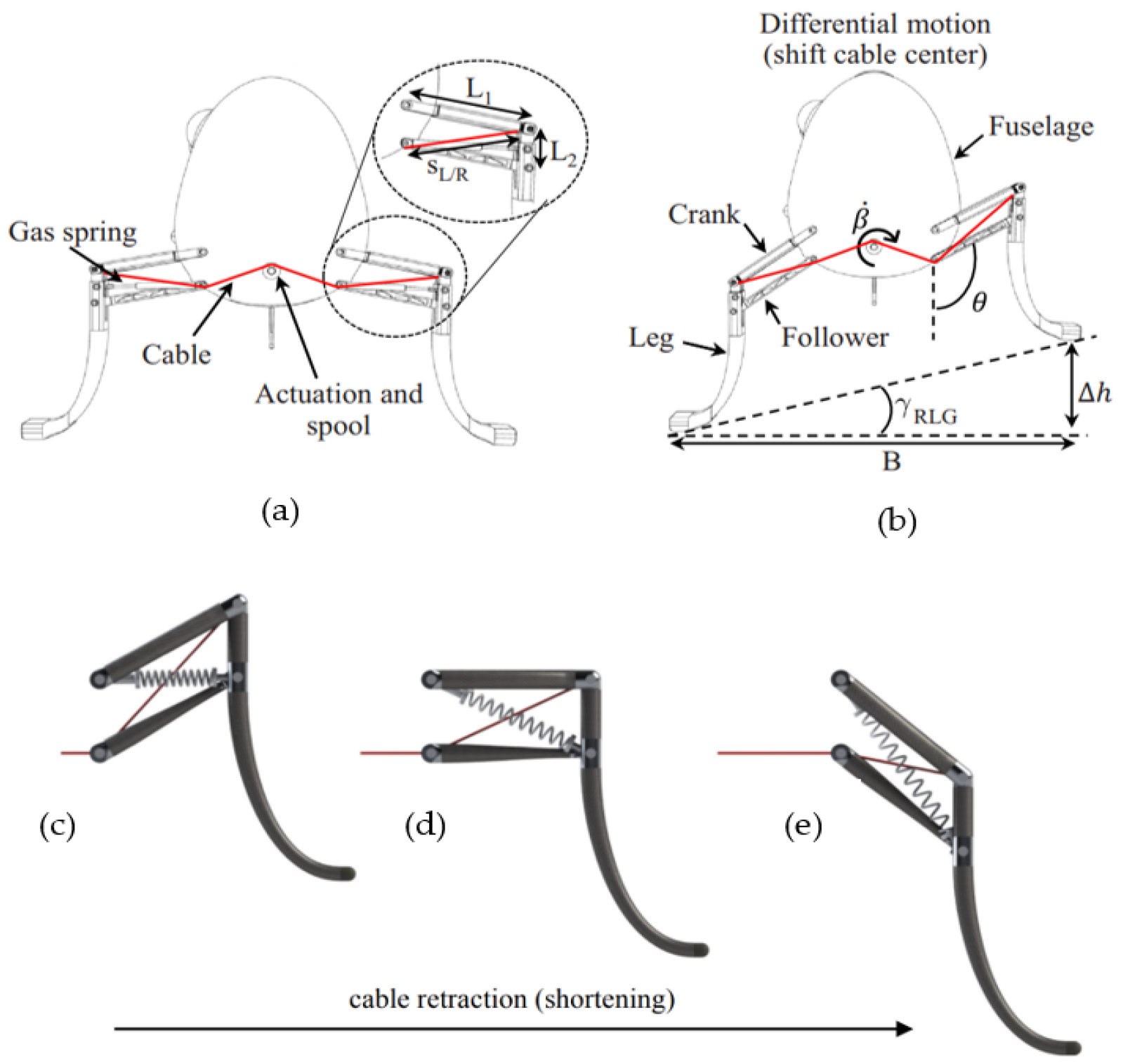
In what follows, a hybrid compliant, four-bar, RLG mechanism design, equipped with two flexible links, as shown in Figure 12, and a timing belt actuation subsystem, is presented and discussed. Timing belts, also known as synchronous belts or toothed belts, are most often used in transporting, indexing, and positioning applications where high torque or force transmission and high acceleration rates are required. The subsystem includes the timing belts (marked in blue), pulleys, and the actuation components that enable motion (Figure 12). The idler and tensioner are crucial for maintaining the necessary tension in the belts and mitigating belt sag caused by distance changes between the tip and the fuselage. In the proposed hybrid compliant system, the belt-driven actuation has been chosen over a cable-driven system, as proposed by León et al. (2021) [11] and discussed earlier in this paper, due to its superior performance characteristics such as reduced vibration, lighter weight, and higher torque transfer capabilities, which collectively offer a greater margin of safety.
Multiple pulleys of different diameters and tooth counts can be utilized along the flexible leg to achieve a greater output moment, Mo,Out, at the end, as shown in Figure 13. This configuration can be customized to amplify the input moment, Mo,In, to attain the desired moment at the tip while preventing slack in the belts between these points. This concept can also be potentially applied to other variable geometry applications, such as morphing aircraft wings, to ensure effective moment transfer to the wingtip.
This type of mechanism has some unique advantages for the design of actuated robotic legs. Namely, the four-bar nature of the design reduces the robotic landing leg to a single degree of freedom (DOF) system, which in turn reduces the number of the drive system’s components required to actuate each flexible leg. The timing belt’s design allows the actuators to be placed within the fuselage, rather than at joints external to the body, as originally used in the four-legged robotic landing gear (RLG) prototype for the UAV rotorcraft developed by Georgia Tech [9]. This, in turn, reduces the total number of actuators and the weight of the moving components. From an actuation perspective, coupling the timing belts of two legs also couples their motion.

4.2. Simulation Tests

In contrast to the conventional cable-driven four-bar link method introduced by León et al. [
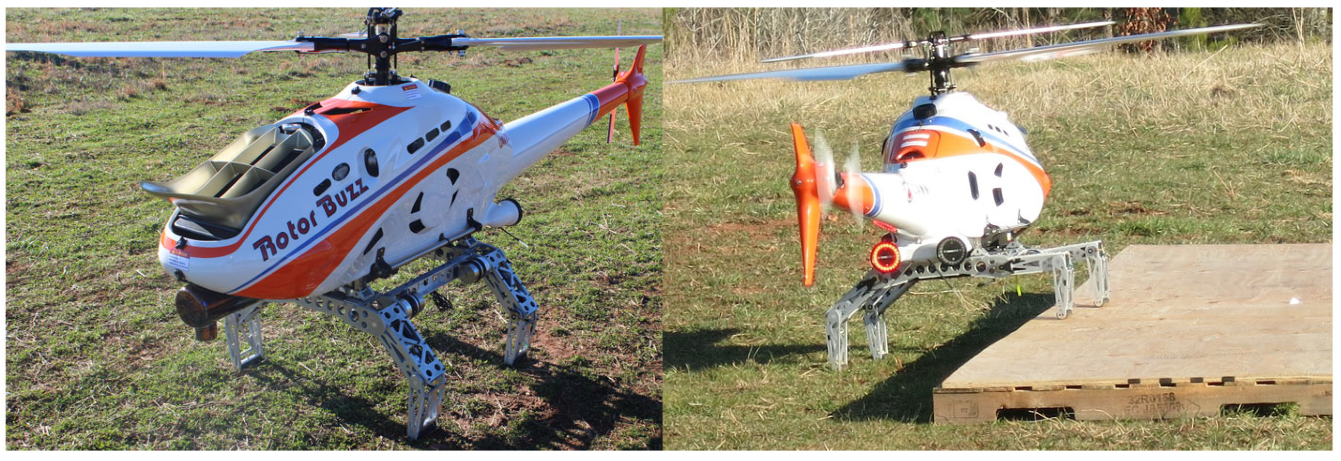
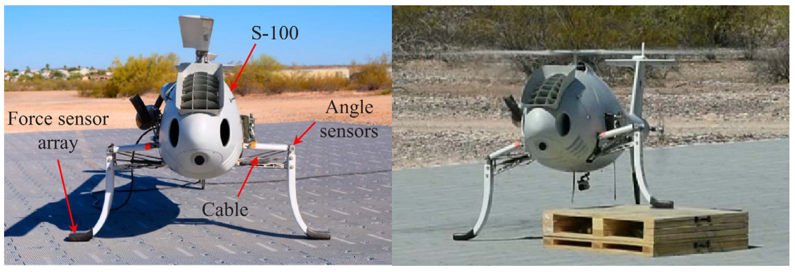
8], which relies on physical articulation tests, the proposed simulation method offers a more efficient and resource-effective approach for testing articulated flexible leg mechanisms. The traditional method involves a complex setup where a crashworthy system lowers the unmanned rotorcraft’s landing gear onto obstacles of heights ranging from 3 to 12 inches (Figure 14), with both legs locking into a “landed” position upon contact. This requires extensive instrumentation, including a test rig, inertial measurement units (IMU), and various sensors to measure vertical displacement, speed, and leg performance, making it labor-intensive and costly.
The proposed simulation method simplifies this process by focusing on the fuselage’s roll angle instead of rotating the ground or using elaborate mechanical systems. The fuselage is rotated to different angles, and the landing gear’s response is evaluated based on its ability to maintain stability and surface contact. The toe-to-toe (horizontal) distance between the legs, D, and the slope γ R L G , which represents the angle between the two legs with respect to a horizontal reference, are key factors in this analysis, as shown in Figure 12. While the toe-to-toe distance is taken as constant for simplicity, it can vary slightly during operation.
By focusing on the UAV’s fuselage’s roll angle and maintaining a consistent toe-to-toe distance, this method would potentially offer a cost-effective and simplified experimental setup while still accurately simulating the dynamic behavior of articulated flexible legs. Then, the use of a single IMU to monitor the roll angle further would reduce the need for multiple sensors and actuators, making the system more efficient. This approach would ensure reliable testing and provide valuable insights into the performance of flexible robotic landing gear systems without the need for complex and expensive test setups. The manufacturing of such an experimental setup and the performance of the experimental tests, however, are beyond the scope of this paper.
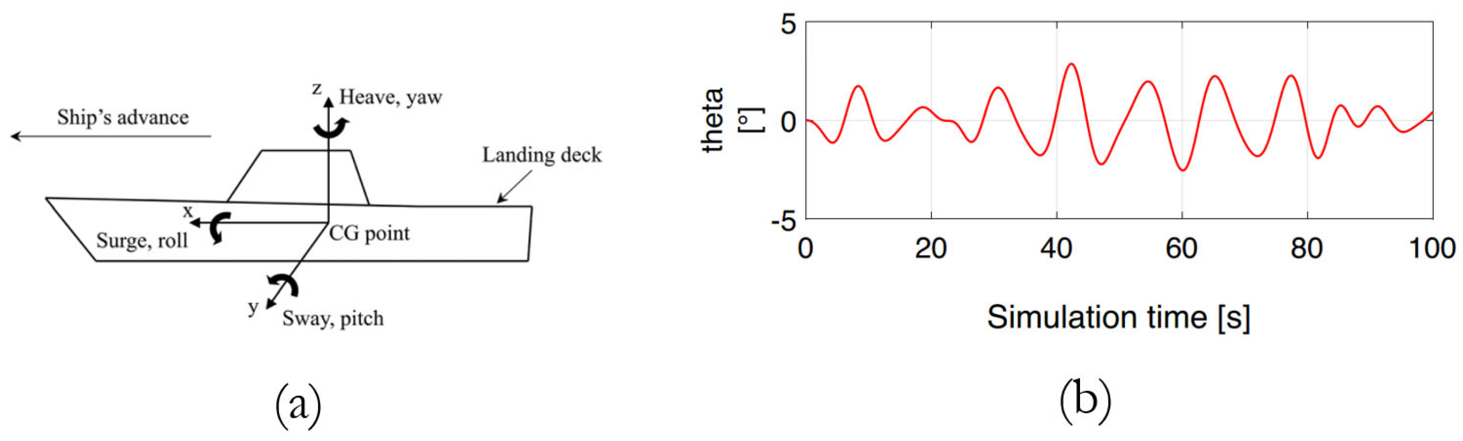
Regarding the FAA recommendations and ship deck dynamics, rotorcraft operating on sloped or mobile surfaces would benefit from a significant expansion in mission capabilities. This is particularly relevant when considering a single degree of freedom aligned with the aircraft’s roll axis (with pitch, roll, and heave movements similar to those illustrated in Figure 15a) [8].
The helicopter–ship landing event simulation incorporates ship motion data to provide a high-fidelity tool for evaluating the complex scenario of a helicopter landing on a ship deck. The wave conditions are specified by the significant wave height, the modal (peak) wave period, and the seaway type (long-crested or short-crested seas). The sea conditions used for the landing simulations are correlated with an accepted sea state code, and the response of the ship to certain sea states can also be varied by specifying the ship speed and ship heading. The sea conditions corresponded to sea state 6 [1], or the test scenario involved the deck of a German Navy F124 “Sachsen class” frigate proceeding at 40 kt at 30° (green wind) with a significant wave height of H s = 6 m and a peak frequency of f = 0.53   r a d s . The resulting maximum motion is a φ m a x = 3.8 ° pitch angle, θ m a x = 2.9 ° roll angle, and z m a x = 3.4 m as shown in Figure 15b [1].
The simulated results for unmanned rotorcraft landing, as reported by León et al. [11], are depicted in Figure 16a, presenting the predictions of an S-100 roll angle response obtained from three simulations. A set of stochastic, varied simulated landings were completed for ground angles γ of 5, 10, and 15° and landing speeds of up to 0.5 m/s (1.6 ft/s). Solid lines represent the average system response, and the same-colored shaded regions represent one standard deviation of the results. Since the feedback controller is not predictive, the simulations show there is an increase in roll angle perturbation as the ground slope increases [11]. Furthermore, León et al. [8] validated their simulations through experimental comparisons, showing a close match between simulation and experimental results in terms of contact timing and roll responses during the first 4–5 s. An additional simulation, using sinusoidal platform motion, also confirmed similar trends, reinforcing the value of simulations as reliable tools for characterizing the S-100 RLG system under various landing conditions (see Figure 16b) [8].

4.3. Dynamics Modeling and Equations of Motion

The approach to modeling a flexible helicopter within a multibody dynamic framework is centered on the floating frame of reference formulation (FFRF) and generalized coordinates and is tailored specifically to address the inherent flexibility of machine components [24]. In the context of a helicopter, which comprises rigid and flexible elements like rotor blades or landing gears, adopting FFRF allows for a comprehensive representation of dynamic behavior while accounting for small elastic displacements (crucial for dynamic controls and stability in the landing phase). Unlike traditional rigid body dynamics, where components are assumed to be perfectly rigid, the FFRF method accommodates the deformations and motions of flexible elements (for example, landing gear, in this case) during landing maneuvers.
The use of FFRF involves describing elastic displacements within floating frames attached to helicopter components, offering a practical means to capture complex deformations without overly complicating the model. This approach avoids the limitations of linearized equations of motion encountered in other modeling methods, ensuring a more accurate representation of the helicopter’s dynamics, including both rigid body motions and elastic deformations. By integrating FFRF into the modeling process, the helicopter’s dynamic response to external forces and control inputs can be simulated and analyzed with greater fidelity, providing valuable insights for design optimization and flight performance evaluation. This section elucidates the simulation tools and their integration as a performance prediction model for the RLG. First, the dynamics modeling and governing equations of motion, using a flexible multibody dynamics tool, with a proven track record for RLG development, are described. A 1R Pseudo-Rigid-Body (PRB) model, followed by the system design, simulation, and controls, is then presented. Actuation and resistance calculations for the system at hand are then discussed, followed by a ship deck motion simulation tool and standardized sea state conditions commonly used in similar modeling and analyses.
The dynamic behavior of a 2D VTOL UAV model, equipped with flexible landing gears, is carefully modeled using flexible multibody dynamics (FMD) equations. This approach enables an accurate simulation of the helicopter’s dynamic response, consisting of two major components: (a) the fuselage, modeled as a 2D rigid body with a uniform mass distribution, and characterized by its mass moment of inertia about the center of mass, and (b) two flexible landing gear legs, which exhibit elastic deformation during dynamic interactions, such as landing.
Key parameters must be defined to model the system accurately, including the length, density, cross-sectional area, modulus of elasticity, and moment of inertia of the landing gears. These parameters influence the overall stiffness, flexibility, and inertia properties, which are critical in determining the dynamic response of the system during landing.
Referring to Figure 11 and Figure 12, when the relative difference between the beams’ length ( L 1 ) and perpendicular distance between them ( L 2 ) is not large enough to significantly impact the moment of inertia of the fuselage, they can effectively form a single composite virtual beam, doubling both the second area moment of inertia ( 2 I ), and the cross-sectional area ( 2 A ), while maintaining the same length, l .
This simplification reduces the computational complexity of the model while still accounting for the flexibility of the legs. Once the overall dynamics are calculated, the legs are discretized again for detailed analysis. More parallel beams could also be added, where the set of compliant members could be virtually represented by an equivalent (i.e., composite) single beam. Then, the equivalent properties can be obtained by multiplying the individual beam’s parameters (second area moment of inertia and cross-sectional area) by the number of beams. This would further simplify the model while still accurately reflecting the added stiffness and flexibility of multiple parallel legs.
A VTOL UAV body with two virtual composite flexible/compliant legs on one axis is illustrated in Figure 17. The middle part, or the fuselage, is assumed as a rigid cylinder with radius a f u s , uniform mass properties, and a mass moment of inertia, I f u s , around the center axis. The two elastic or flexible links are modeled as identical Euler–Bernoulli beams with length l , constant mass density ρ , and constant bending stiffness E I , where I is the second area moment of inertia of each flexible links, and A is the cross-sectional area of each beam. The Euler–Bernoulli beam theory assumes slender, long beams where cross-sectional deformations are negligible, and deformation is primarily due to bending [25]. This theory, suitable for fixed-free boundary conditions, enables accurate modeling of the legs’ bending behavior.
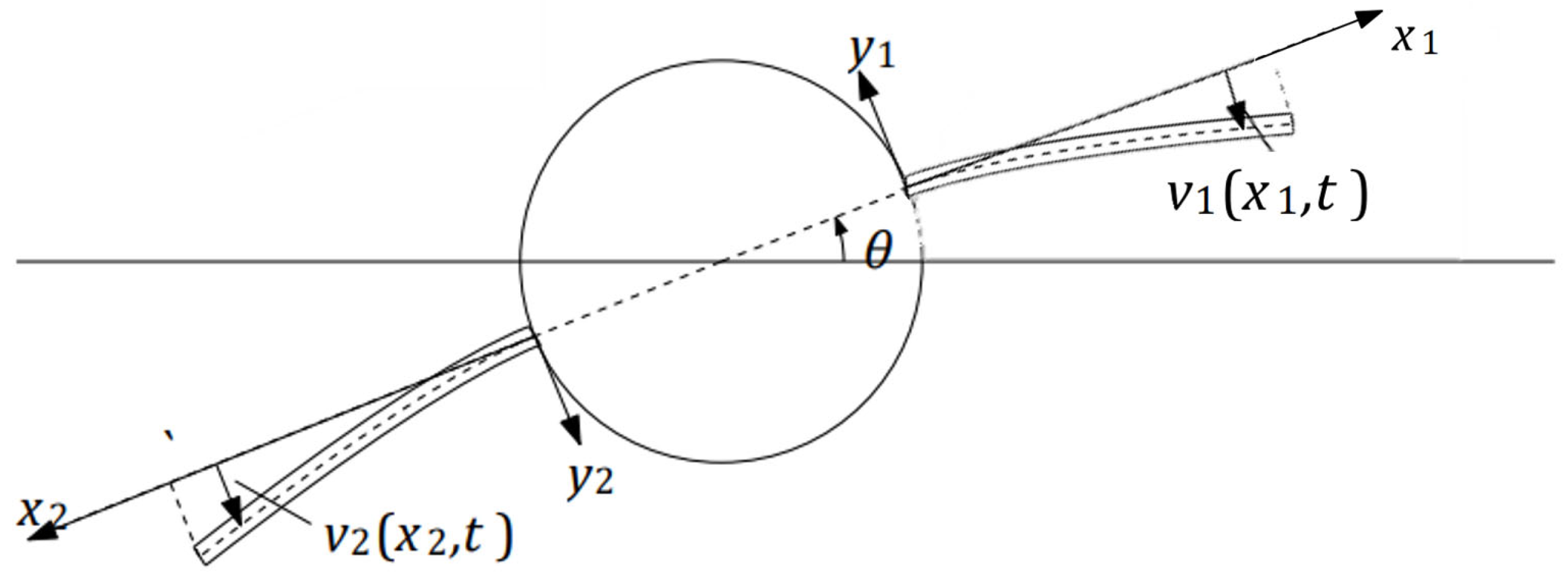
In the case of robotic landing gear, the flexible legs undergo bending deformation due to forces exerted during landing and takeoff. Let v 1 ( x 1 , t ) and v 2 ( x 2 , t ) be the lateral displacement due to flexible motion of each leg shown in Figure 17, where x 1 and x 2 are coordinates along the respective beams, measured from their attachment points on the fuselage.
The deflection of each flexible landing gear leg, v i x i , t , as expressed in Equation (1), includes quadratic ( x i 2 ) and cubic ( x i 3 ) terms. These terms arise from the Euler–Bernoulli beam theory, which models the bending of slender beams while neglecting rotary inertia and shear deformation [26]. These higher-order terms capture the curvature and bending behavior under the assumption of small elastic deformations.
v i x i , t = x i 2 q 1 , i t + x i 3 q 2 , i t , i = 1,2
Using the Ritz method and the generalized equations of motion for a continuous system, the displacement field v x , t may be approximated by [24]
v x , t = i = 1 n ψ i x q i t
The shape functions, ψ T x , and set of generalized coordinates, q T , are assumed as
Ψ x = ψ 1   ψ 2     ψ 3       ψ 4       ψ 5   ,       q T = θ   q 1,1     q 1,2       q 2,1     q 2,2  
The generalized coordinates, q T , consist of the reference coordinates (rigid), θ , and elastic coordinates, q i , j , respectively. The differential equations of motion of the multibody system can then be written as
M q ¨ + K q = Q v
where Q v is the vector of generalized forces that arises from differentiating the kinetic energy with respect to time and with respect to the generalized coordinates of the rigid central body:
Q v = c b I . f t o t + g t o t + g e + Q e
where c b I is the rotation matrix, f t o t is the total force acting on the body (resolved in the inertial frame), g t o t represents the total torque on the undeformed body (resolved in the body frame), for small elastic deformations, g e = 0 is the incremental torque acting on the deformed body due to elastic deformation (resolved in the body frame), and Q e is the generalized force acting on the elastic coordinates [27].
Q e = u t   d v = B Ψ C b 1 f p , t r  
The expressions for the potential energy, V , stiffness matrix, k e , energy of external forces, Q e , and the generalized forces acting on the elastic coordinates are written as
V = 1 2 q T K q   k e = B Ψ E Ψ d v
where E is the matrix of elastic moduli for an isotropic material. The kinetic energy of the system, T, consists of contributions from the fuselage and both legs:
T = T fus   + T leg   1 + T leg   2
Expressions for the components of total kinetic energy, T, are as follows:
T fus   = 1 2 I θ ˙ 2 T leg   1 = 1 2 q ˙ M leg   q ˙ T leg   2 = 1 2 q ˙ M leg   2 q ˙
knowing the mass matrix, M , is defined as [24]:
M = A l ρ x Ψ Ψ d x
The system’s overall (total) mass matrix, M , consists of contributions from the M leg   1 , M leg   2 , and M fus   mass matrices, defined as follows:
M leg   1 = 0 l Ψ 1 T x 1 Ψ 1 x 1 ρ d x 1 M leg   2 = 0 l Ψ 2 T x 2 Ψ 2 x 2 ρ d x 2 M fus   = I f u s 0 0 5 × 5
where Ψ 1 and Ψ 2 represent the shape symmetric matrices of the first and second legs, ρ is the material density, and the mass moment of inertia, I f u s .
Then, the mass matrices for leg 1, M l e g 1 , and leg 2, M l e g 2 , are given by
M l e g 1 = 2 ρ A l a + x 1 2 a x 1 2 + x 1 3 a x 1 3 + x 1 4 0 0 a x 1 2 + x 1 3 x 1 4 x 1 5 0 0 a x 1 3 + x 1 4 x 1 5 x 1 6 0 0 0 0 0 0 0 0 0 0 0 0
M l e g 2 = 2 ρ A l a + x 2 2 0 0 a x 2 2 + x 1 3 a x 2 3 + x 2 4 0 0 0 0 0 0 0 0 0 0 a x 2 2 + x 1 3 0 0 x 1 4 x 2 5 a x 2 3 + x 2 4 0 0 x 2 5 x 2 6
The potential energy of the system, V , is expressed as
V = 1 2 I l E x 2 ψ 2 x 2 2 2 d x = 1 2 q T K   q
where E(x) is the matrix of elastic moduli, and the stiffness matrix, K , is defined as
K = I l E x 2 ψ 2 x 2 2 ψ 2 T x x 2 d x
One can use the shape function ψ 1 x to form the stiffness matrix for the first composite compliant leg.
ψ 1 x = [ a + x 1 x 1 2           x 1 3 0 0 ] ψ 1 x x 1 = [ 1 2 x 1 3 x 1 2 0 0 ] 2 ψ 1 x 1 2 = [ 0 2 6 x 1 0 0 ]
where
K l e g 1 = ( 2 I ) E l 0 0 0 0 0 0 4 12 x 1 0 0 0 12 x 1 36 x 1 2 0 0 0 0 0 0 0 0 0 0 0 0
and the shape function ψ 2 x to form the stiffness matrix for leg2,
ψ 2 x = [ ( a + x 2 ) 0 0 x 2 2 x 2 3 ] ψ 2 x x 2 = [ 1 0 0 2 x 2 3 x 2 2 ] 2 ψ 2 x 2 2 = [ 0 0 0 2 6 x 2 ]
where
K l e g 2 = 2 I E l 0 0 0 0 0 0 0 0 0 0 0 0 0 0 0 0 0 0 4 12 x 2 0 0 0 12 x 2 36 x 2 2

4.4. Control Strategy

In this paper, the VTOL UAV landing gear’s position and control were managed through proportional-derivative (PD) controllers, applied to a linear dynamics model of the system. While PD control is typically used for linear systems, it can still effectively regulate the motion of the RLG by adjusting the proportional and derivative gains. This approach ensures that the helicopter maintains stabilization during landing, including under varying ship deck conditions. The compliant robotic landing gear system is defined by a set of five state variables, representing the angular orientation and positions of its flexible legs. The initial positions of the system are given by the following vector:
x 0 = θ   q 1,1     q 1,2       q 2,1     q 2,2  
where θ represents the initial angular orientation of the fuselage of the helicopter, while q 1,1 and q 1,2 correspond to the positions and curvatures of the right flexible leg. Similarly, q 2,1 and q 2,2 represent the positions and curvatures of the left flexible leg. These initial values reflect a symmetric starting condition where both legs are pre-configured with initial curvatures, preparing the system for controlled descent and landing, while the initial velocities of all state variables are set to zero.
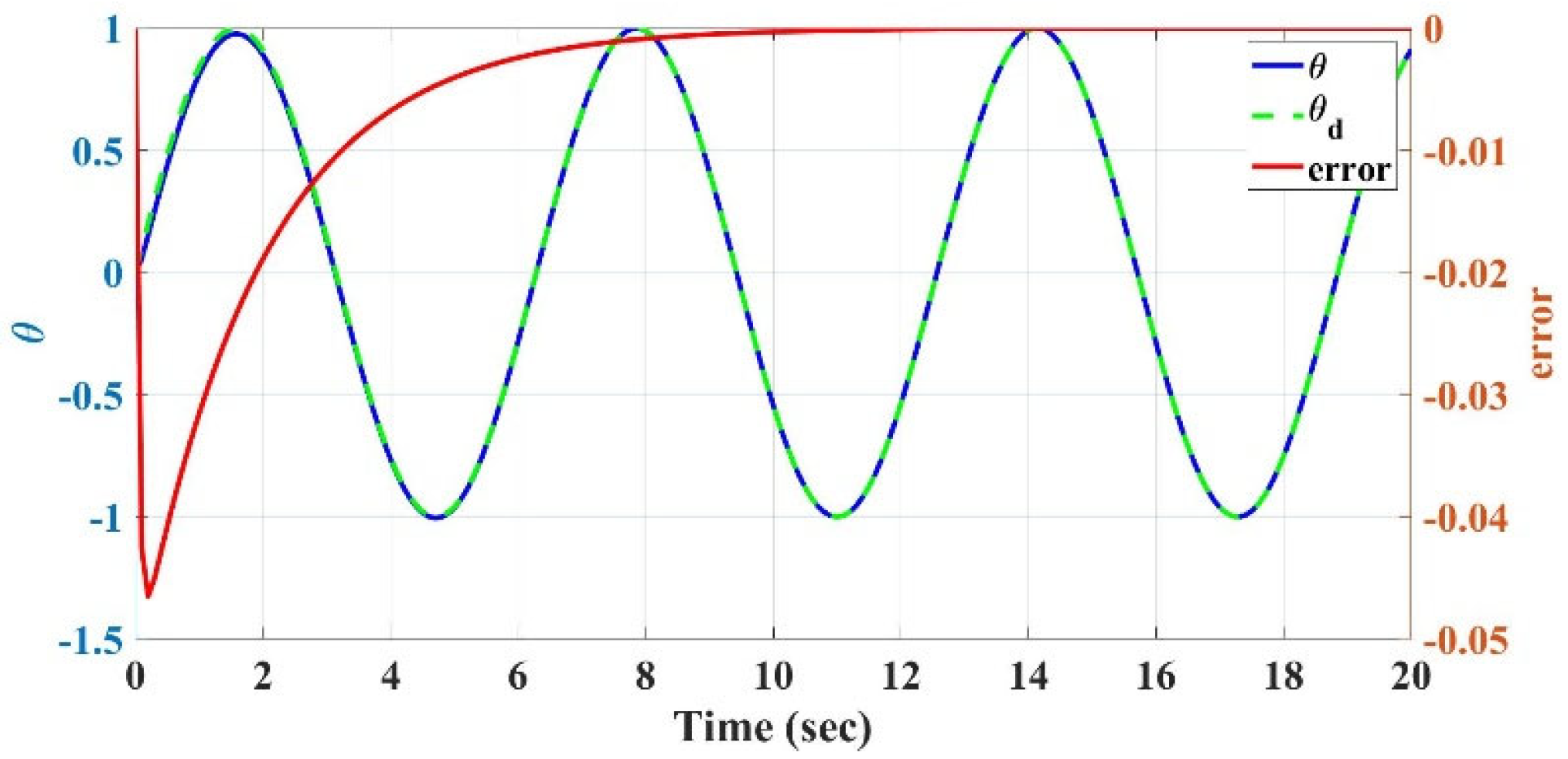
The control inputs for the flexible robotic landing gear are designed based on the error between the actual and desired positions of the landing gear. The control system aims to regulate the fuselage roll angle, θ(t), ensuring that the landing gear follows a desired trajectory. The control strategy accounts for both the roll angle error, θ ~ t = θ t θ d t , and the rate of change in this error. The desired roll angle, θ d t , is defined as a sinusoidal function: θ d t = s i n t .
The control law used to stabilize the system is given by
u t = I t θ ¨ r K d θ ˙ ~ + λ θ ~
where
  • I t is the total moment of inertia about its center of mass (fuselage plus landing legs).
  • θ r is the reference roll angle.
  • K d is a derivative control gain.
  • λ is a proportional control parameter.
  • θ ~ t is the error between the actual roll angle θ t and the desired roll angle.
Additionally, the reference roll angle velocity θ r ˙ is updated according to the following rule:
θ r ˙ = θ d ˙ λ θ ~
where θ d ˙ is the rate of change in the desired roll angle, which for θ d t = s i n ( t ) is θ d ˙ t = c o s ( t ) .   λ is a tuning parameter in the control law that scales the impact of the roll angle error, θ ~ , on the desired rate of change. The parameter λ acts as a proportional gain, ensuring that the control response is sensitive to discrepancies between the actual and desired roll angles.
This control law ensures that the roll angle of the fuselage, θ t , tracks the desired sinusoidal trajectory by continuously adjusting the control input u t . The derivative term K d θ ˙ ~ + λ θ ~ stabilizes the system, minimizing oscillations and ensuring smooth behavior. Here, K d is a derivative control gain, which regulates the system’s response to changes in the error signal. By appropriately tuning K d , one can control the rate at which the error θ ~ t is driven to zero over time, ensuring that the actual roll angle converges to the desired trajectory.
This approach allows the compliant robotic landing gear to perform controlled landings by dynamically adjusting the system’s behavior based on real-time feedback from the fuselage’s roll angle and the desired trajectory. The simulation runs for 20 s to demonstrate the stability and effectiveness of this control mechanism in guiding the landing gear.

4.5. Pseudo-Rigid-Body (PRB) Model

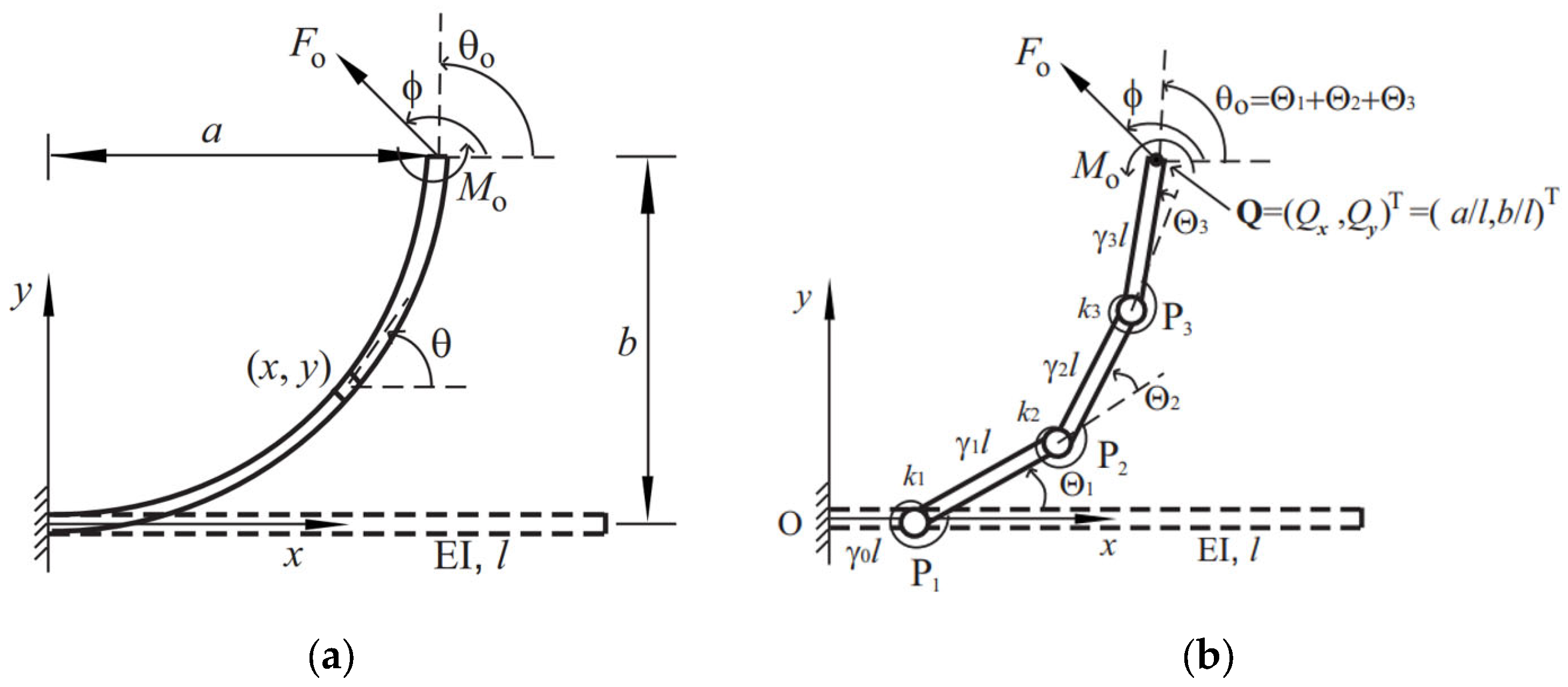
Building upon the modeling of compliant legs using cantilever beam equations, this study employs the Pseudo-Rigid-Body (PRB) model to simplify the deflection behavior of flexible elements into a more manageable and predictable framework. Specifically, the single revolute (1R) PRB model is utilized to estimate the allowable error bounds for beam tip deflections.
The PRBM approach bridges the gap between compliant mechanisms and rigid-link designs by approximating the behavior of flexible elements using kinematic trajectories and force–deflection relationships. The PRB 1R model shown in Figure 18b consists of two rigid links connected by a pin joint and a torsion spring. The location of the torsion spring from the origin is determined by the characteristic radius factor, ( 1 γ ) l , and the horizontal and vertical positions ( a , b ) of the tip point are determined by a Pseudo-Rigid-Body (PRB) angle, Θ [28]. In Figure 18a, θ 0 is the angle between the horizontal and the beam’s longitudinal axes.
In practical designs, the slope angle is often limited by the maximum stress of the beam, happening at the fixed end for a beam with monotonic curvatures. To prevent the beam of a rectangular cross-section from failure, the condition of σ a l l o w t M m a x 2 I z z , where σ a l l o w = σ m a x S . F . , with the applicable/intended safety factor (S.F.), must be satisfied. Here, σ m a x is the material yield strength, σ a l l o w is the allowable stress, and t is the height of the cross-sectional area. For the purposes of this design, the safety factor has been set to 1 for optimization (i.e., σ a l l o w = σ m a x ), though this value can be adjusted depending on the specific requirements and design preferences of the engineer.
To determine the maximum slope angle, θ 0 , m a x , Su [29] introduced a beam slenderness ratio of l t = 100 , and a material flexibility of σ a l l o w E = 30 into Equation (23) below:
2 l t σ a l l o w E β + 2 α a l s i n ϕ + b l c o s ϕ
The larger these two quantities, the larger slope angle the beam can be bent to.
The right side of Equation (23), M n e t , n o r m and M n e t , represents the normalized and the dimensional net moment applied to the fixed end of the beam, respectively, where M n e t = M n e t , n o r m E I l .
M n e t , n o r m = 2 l t σ a l l o w E
The 1R model Expression (25) below shows the characteristic radius factor, γ 1 R , M , the parametric angle coefficient, c 1 R , θ , and the stiffness coefficient, k 1 R , Θ (refer to [28]).
γ 1 R , M = 0.735 , θ 0 = c 1 R , θ Θ , c 1 R , θ = 1.516 , k 1 R , Θ = 2.064
where a is horizontal tip deflection and b is vertical tip deflection (Figure 18), and the normalized tip deflection a l   a n d b l , can be found using Equation (26) from the tip slope angle, θ 0 , utilizing parameters from the optimal PRB 1R model Equation (25), as reported by [28]:
b l = 0.735 s i n Θ = 0.735 s i n θ 0 / 1.516 , a l = 1 0.735 ( 1 c o s θ 0 / 1.516 )
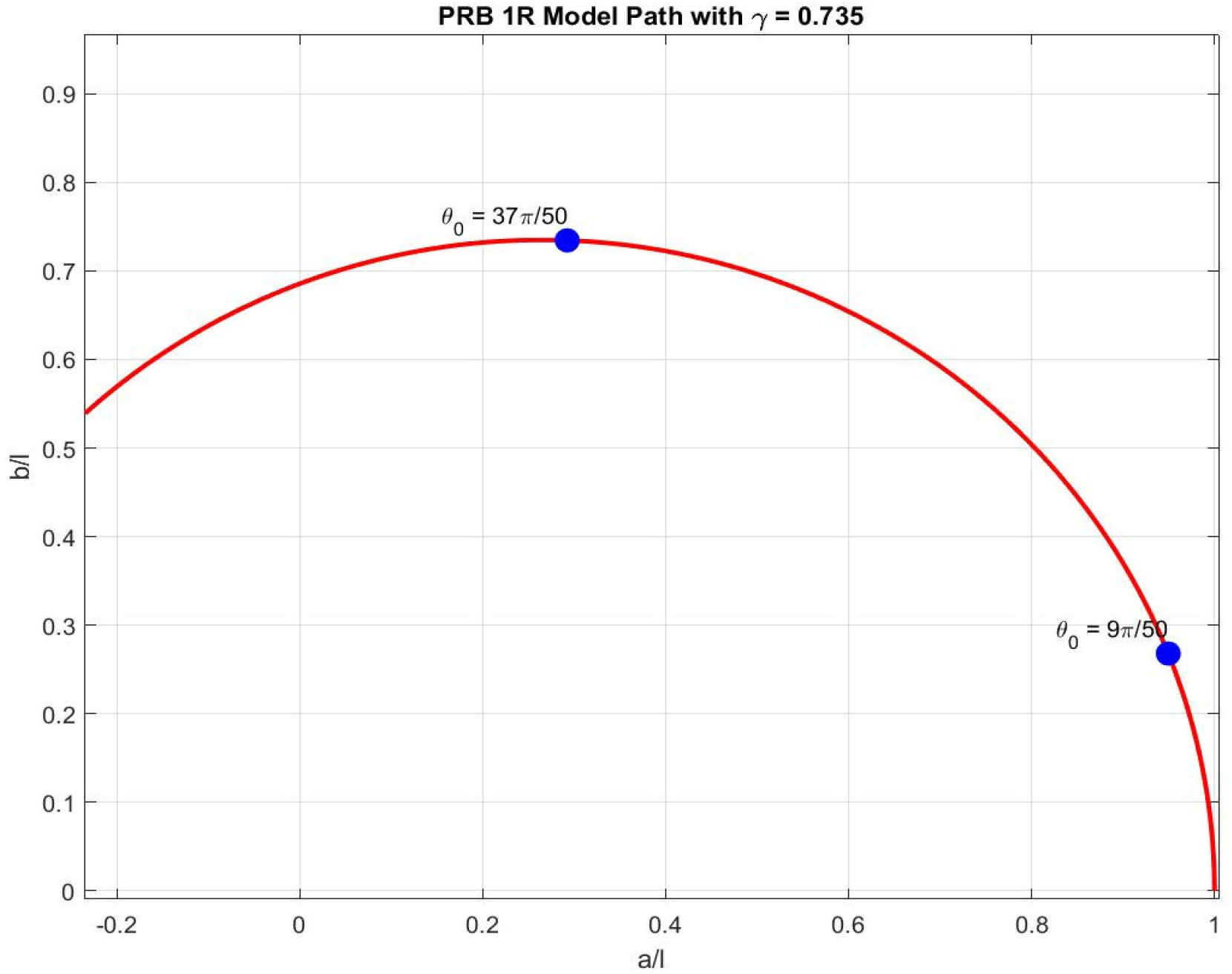
Figure 19 below illustrates the tip deflection of the PRB 1R model path with specified parameters and markers for θ 0 = 9 π / 50 ,   a n d   37 π / 50 .

4.6. Resistance and Actuation Calculations

In what follows, the pertinent structural and actuation subsystems, for the proposed hybrid, compliant, four-bar, VTOL UAV RLG system, are briefly discussed. These subsystems include the structural mechanism, timing belts (marked in blue), pulleys, and the actuation components that enable motion, as shown in Figure 12. The idler and tensioner are crucial for maintaining necessary tension in the belts and mitigating belt sag caused by distance changes between the tip and the fuselage.
As also mentioned earlier, a belt-driven system has been chosen over a cable-driven system to actuate the two flexible four-bar leg mechanisms, due to the advantages, such as reduced vibration, lighter weight, and higher torque transfer capabilities, collectively offering a greater margin of safety.
Consider a system with two sloped legs where the belts connect on a center gear, as shown in Figure 12. This configuration enables symmetric-differential leg motion, with one leg moving up while the other moves down. Referring to Figure 12, the vertical displacement or the deflection of flexible right link, b R , and the tip horizontal position, a R , the right leg position, caused by the external moment, M 0 , R , at the tip of the flexible link, can be calculated as function of the link length, L 1 , and the tip slope angle, θ 0 , R , from Equation (27):
b R = 0.735 L 1 s i n θ 0 , R / 1.516 , a R = L 1 0.735 ( L 1 c o s θ 0 , R / 1.516 )
using the parameters, γ 1 R , M ,   θ 0 = 1.516 Θ ,   a n d   k 1 R , Θ = 2.064 , as given in Expression (25).
In the symmetrical leg movement, the position of the left leg would be of the same magnitude but in the opposite direction of the right one (i.e., b R = b L ). Then, the total vertical displacement is: h = b R + b L , and in the symmetric case, h s y m = 2 b R .
The total leg spread D is given by: D = a R + a L + L 0 , where L 0 = 2 a f u s . Thus, in the symmetric configuration: D s y m = 2 a R + 2 a f u s , using the leg positions determined through Equation (27), the ground angle γ s y m can be calculated using Expression (23) below:
γ s y m = t a n 1 h B = t a n 1 2 b R 2 a R + 2 a f u s ,   or γ s y m = t a n 1 0.735 L 1 s i n θ 0 / 1.516 L 1 0.735 ( L 1 c o s θ 0 / 1.516 ) + 0.5 L 0
To identify the material and beam slenderness ratio of the flexible links, l/t, while sustaining without failure under a pure moment load (i.e., maximum stress), one should consider the maximum ground angle and vice versa. Equation (28) shows that the maximum ground angle is related to the length of the beam and the max tip slope angle, θ 0 , m a x . Due to the design limit, (l/t)max= 100 for the materials of choice (aluminum (7075)/titanium Ti-13), as discussed earlier in this paper. The tip slope angle calculated for a beam made of titanium (Ti-13) is 115 deg, and for a flexible link made from aluminum (7075) it is 80 deg. By setting these maximum slope angles for each material and considering L 1 and L 0 , one can then calculate the maximum achievable ground angle for the RLG design. For a flexible leg mechanism (where L 0 = 2 L 1 ) , using flexible links made from titanium (Ti-13) would lead to a maximum ground angle of 26.57°. However, if aluminum (7075) construction is used, the flexible leg mechanism can be bent to achieve a ground angle of 19°.
The ratio of σ a l l o w E (allowable stress over the modulus of elasticity) is used to determine the maximum weight that fuselages can safely sustain when supported by flexible legs mechanism made of Ti-13 or aluminum 7075, under pure moment loads (determined by maximum stress). For these materials, the flexibility ratio ( S y E ) of Ti-13 to aluminum 7075 is 10/7, reflecting their respective material flexibilities [30]. Ti-13 demonstrates higher flexibility compared to aluminum 7075.
To determine the net moment required to bend the beam and reach maximum stress, the dimensional moment from Equation (23) is used, knowing the beam’s length, l , thickness, t , width, w , and modulus of elasticity, E . For Ti-13 and aluminum, a large moment is required to sustain substantial fuselage weights. However, one may calculate the allowable fuselage weight, should a different material be used. For example, a flexible leg mechanism made of polypropylene would support a much lighter fuselage weight when subjected to similar conditions, due to its much lower elastic modulus.
Finally, by examining the relationship between the forces V 1 , V 2 , W (acting on the leg), and the moment applied at the fuselage’s center (leading to a symmetric movement), the net moment for each flexible link (beam), M n e t , can be derived using the following equation:
M n e t = 2 l t σ a l l o w E E w t 3 12 l = W 4 ( 0.5 L 0 + L 1 )
This equation highlights the relationship between the net moment, the beam’s geometry (l, t, w, L0, and L1), material properties (E, and σ a l l o w ), and the weight of the system, W, providing crucial insights for optimizing the structural performance of flexible landing gear.

4.7. Compliant Mechanism: Design Optimization

In recent years, compliant mechanisms have gained significant attention as a viable alternative to traditional rigid body systems connected by conventional pin joints, especially in the creation of machine tools for small-scale applications. Unlike traditional mechanisms, compliant mechanisms are flexible, monolithic structures that derive their motion from the elastic deformation of certain parts, known as flexure hinges. This unique characteristic of compliant mechanisms provides several advantages over conventional mechanisms, consisting of rigid links connected through revolute joints. These advantages include, but are not limited to, enhanced accuracy and reliability, along with lower wear, backlash, maintenance, and weight, accomplished through topology optimization and advanced manufacturing methods [31].
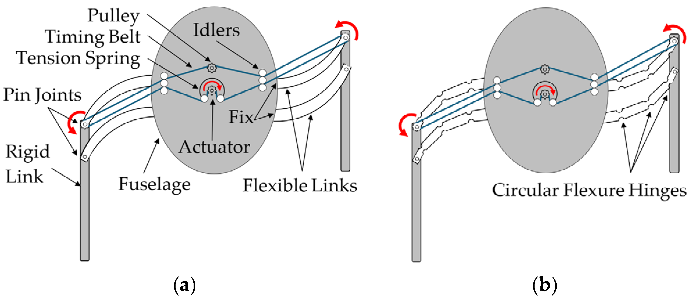
A prominent example is circular notch hinges (Figure 20, adapted from [32]) formed by machining symmetrical circular patterns along each side of a beam, resulting in a slender, flexible path between two rigid segments. These notched flexures are nearly 100% efficient during assembly, offering a notable advantage over traditional leaf flexure hinges. Optimizing the geometry parameters of circular flexure hinges, thickness (t), radius (R), and width (w), further contributes to the overall system optimization, as each enhancement in hinge design positively impacts the entire design process.
In a recent publication by Kabganian and Hashemi [12], a new accurate compliance/stiffness equation for t/R ranges of 0.2 to 0.8 was introduced, targeting improved modeling accuracy for torsional stiffness and rotational compliance α z / M z in circular flexure hinges (CFHs). Utilizing a hybrid PRBM-FEM approach, this model achieved improved accuracy in flexure hinge representation, resulting in the following empirical stiffness Equation (30):
k α z = E w C 0 + C 1 R 1 + C 2 t 2 + C 3 R . t + C 4 R . t 2 + C 5 R . t 2 + C 6 t 3 + C 7 t + R 2 . t 2 )
where the coefficients C 0 t h r o u g h C 7 , originally determined and reported in the authors’ earlier publication [12], are presented in Table 1 below. Additional parameters are illustrated in Figure 20.
The current study adopts Equation (30) to improve design accuracy and minimize error in compliant mechanism applications, balancing simplicity in manufacturing with a safe, controllable design. By enabling precise control of torsional movement, this approach enhances system reliability—a critical factor for controlled performance.

4.8. Optimal 3-SFH Using the PRB Model

After determining the net moment applied to the fixed end of the cantilever beams and its relationship with the slope angle, the optimal design of circular flexure hinges (CFHs) is achieved using the kinostatic (kinematic and static) equations, as derived and presented by Su [29] for cantilever beams subject to tip loads. Optimizing the geometric parameters of circular flexure hinges, i.e., thickness (t), radius (R), and width (w), is crucial for enhancing the performance and reliability of compliant mechanisms. As shown in Figure 20 (adapted from [32]), these parameters significantly influence the mechanical behavior and structural integrity of the hinges.
Building on the compliance/stiffness Equation (30), the present study uses the modeling of torsional stiffness and rotational compliance ( α z / M z ) in CFHs. Utilizing a hybrid PRBM-FEM approach, Equation (30) was developed which is accurate for t/R ratios ranging from 0.2 to 0.8. The enhanced flexure hinge representation enables precise control of torsional movement and improved system reliability, i.e., a critical factor for controlled performance in compliant mechanisms.
Based on the earlier modeling and analysis of compliant legs using cantilever beam equations presented earlier in this paper, in what follows, the extension to the design and optimization of three-series flexure hinge (3SFH) compliant legs [29], incorporating the Pseudo-Rigid-Body (PRB) method, is presented. The focus here is on the design optimization of circular flexure hinges through an accurate analytical model with variable parameters, as presented in an earlier work by the authors [12], aimed at assessing compliance and rotational precision under various loads. These efforts are directed at enhancing the design of compliant legs equipped with circular flexure hinges, which have demonstrated accurate performance as torsional springs. The PRB 3R model shown in Figure 21 (right) consists of four rigid links connected by three pin joints and three torsion springs [12], necessitating the calculation of compliant stiffness specific to the circular flexure hinges [29]. For the 3R model, the deflection angles and spring stiffness in Figure 20, right, are denoted by Θ 1 , Θ 2 , and Θ 3 and k 1 , k 2 , and k 3 , respectively. The ratios of the length of each bar to the total length of the system are characteristic radius factors, denoted by γ 0 , γ 1 , γ 2 , and γ 3 , summing up to 1.
Considering the initially straight, continuous, cantilever beam (a) and the articulated PRB 3R model (b), Figure 21 shows deflections when the system is subjected to external tip loads of F 0 and M 0 . The direction of the end tip force, F 0 , with respect to the x-axis is denoted by the angle ϕ . The parameters θ 0 , a , and b are the tip slope angle and the horizontal and vertical tip deflections, respectively. α and κ are the nondimensional force index and load ratio, respectively, defined as [29]
α = F 0 l 2 2 E I , κ = β 2 4 α , β = M 0 l E I
The position of the tip point is Q = Q x , Q y T = a l , b l T , where a l and a l are the normalized tip deflection, and the slope angle, θ 0 , of the 3R chain is calculated as
Q x = γ 0 + γ 1 c 1 + γ 2 c 12 + γ 3 c 123 Q y = γ 1 s 1 + γ 2 s 12 + γ 3 s 123 θ 0 = Θ 1 + Θ 2 + Θ 3
The torque values at the three pin joints are given by
τ 1 τ 2 τ 3 = J T F x l F y l M 0
where F x = F 0 c o s ϕ , and F y = F 0 s i n ϕ . The matrix J T is the transpose of the nondimensional Jacobian of the 3R chain obtained by differentiating kinematic Equation (32), written as
J T = γ 1 s 1 γ 2 s 12 γ 3 s 123 γ 1 c 1 + γ 2 c 12 + γ 3 c 123         1 γ 2 s 12 γ 3 s 123                   γ 2 c 12 + γ 3 c 123                                   1     γ 3 s 123                                           γ 3 c 123                                                       1
where c 1 = c o s Θ 1 , s 1 = s i n Θ 1 , c 12 = c o s ( Θ 1 + Θ 2 ) , s 12 = s i n ( Θ 1 + Θ 2 ) , c 123 = c o s ( Θ 1 + Θ 2 + Θ 3 )   , a n d   s 123 = s i n ( Θ 1 + Θ 2 + Θ 3 ) . Assuming the spring torques are proportional to the PRB angles, i.e.,
τ i = k i Θ i , i = 1,2 , 3
the spring stiffness, κ i , can then be normalized to
k i = k Θ i E I l , i = 1,2 , 3
By substituting definitions (35) and (36) into (33), the normalized and nondimensional statics equation is obtained as
k Θ 1 Θ 1 k Θ 2 Θ 2 k Θ 3 Θ 3 = J T 2 α c o s ϕ 2 α s i n ϕ β
where the definitions (31) are used.
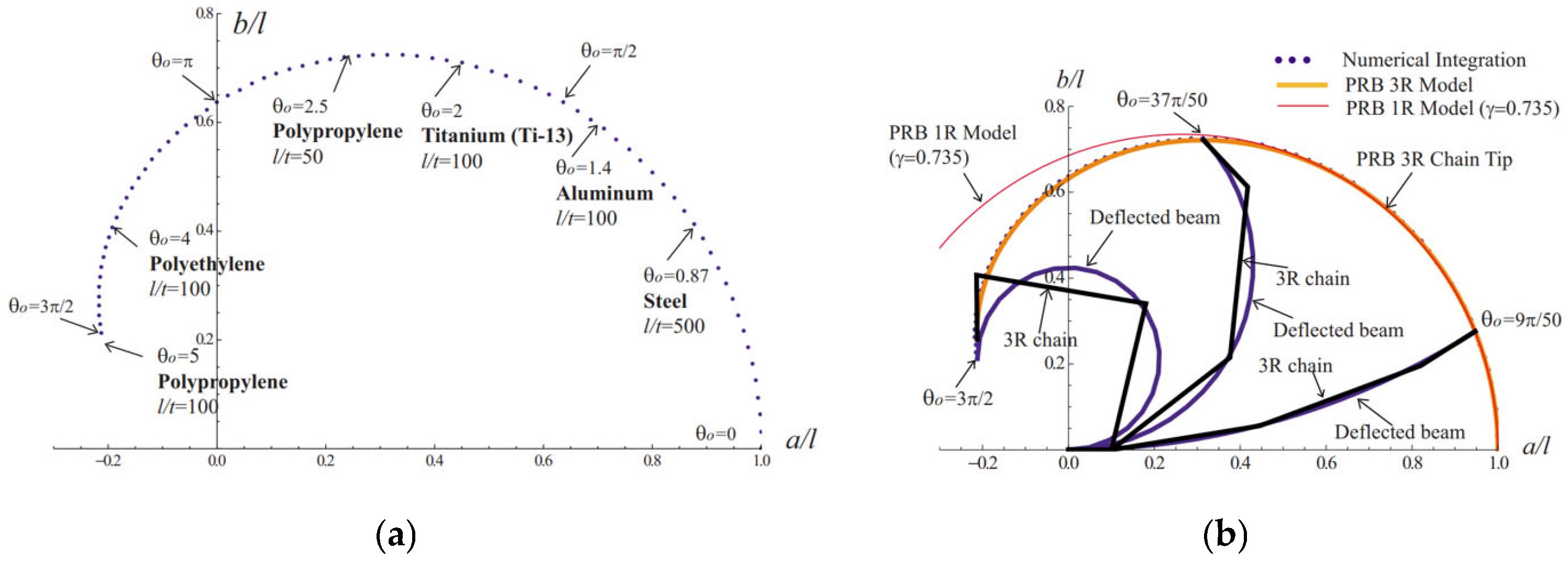
Figure 22a illustrates the fail-free, achievable tip slope, θ 0 , m a x , for a flexible beam subjected to a tip moment, influenced by the beam’s material properties, E, and slenderness ratio, l / t . The values of the l/t ratio for various materials are from Reference [30]. As can be seen in Figure 22, titanium (Ti-13) and aluminum (7075) beams with l/t = 100 can sustain a tip bending angle of 2 rad (115°) and 1.4 rad (80°), respectively, without failure, whereas a steel (4140) beam of l/t = 500 can only be bent to an angle of 50°. A PRB 3R model for determining the large deflection of cantilever beams subject to tip loads was presented by Su [29] on the system’s geometric parameters and spring coefficients and showed that they are independent of external loads. The comparison between 1R and 3R can be seen in Figure 22b. The implementation of these concepts in the development, analysis, and optimization of the proposed hybrid compliant RLG system, and the relevant results, will be reported later in this paper (refer to Section 5).

5. Results and Discussion

In what follows, various aspects related to the design, analysis, and optimization of the proposed hybrid robotic landing gear (RLG) system for VTOL UAVs, and the results obtained from various analyses are presented and discussed. This section is divided into the three following subsections: Flexible MBD Simulation (Section 5.1), RLG Design with Flexible Legs (Section 5.2), and Optimal Design of Articulated RLG Using Flexure Hinges (Section 5.3).

5.1. Flexible MBD Simulation

The roll motion dynamics and control of the flexible robotic landing gear (RLG) system was simulated using MATLAB’s ODE solver, using a PD-controller, and integrating the equations of motion over a defined time span of 20 s. This approach is essential for analyzing the performance of VTOLs/helicopters, particularly the role of flexible landing gears under varying operational conditions. Through this simulation process, detailed analysis was conducted on the helicopter’s critical operational phases—takeoff and landing—emphasizing the behavior of the flexible landing gears in response to external excitation loads. The system’s response to ship deck motion and control inputs, as described in [8], is evaluated and illustrated in Figure 23 and Figure 24, respectively, captured at 2.9 and 15.4 s.
In the context of PD-controlled roll angle motion for a VTOL UAV, the actual roll angle, θ , is found to closely follow the desired roll angle, θ d (see Figure 25 and Figure 26). This effective tracking of θ d by θ indicates the stability of the implemented PD control system, crucial for safe and precise helicopter operation. The error between θ and θ d leads to a well-controlled roll motion.
As can be seen from Figure 25, the analysis of the RLG’s rotation using a PD controller with K P = 1 and K D = 2 reveals an effective and stable tracking performance. The result indicates that the RLG’s rotation stabilizes around the desired angle relatively quickly in response to a sinusoidal roll angle acting at the center of the fuselage, achieving a settling time of approximately 5 s. During this time, the landing gear achieves full contact with both legs and matches the deck motion within 5 s of descent onto the platform. The overshoot observed in the response is moderate, approximately 0.3 radians (i.e., approximately 17.19°), which correlates with findings from previous research that confirm settling times between 4.5 and 5 s for similar systems.
As illustrated in Figure 26, using higher PD control gains ( i . e . , K P = 10 and K D = 20 ) achieves an even faster system stability. The results show that the RLG’s rotation stabilizes around the desired angle more quickly compared to lower gains, with a settling time of less than 2 s, and the overshoot is reduced to approximately 0.04 radians (2.29°). While higher gains demand greater control effort, the increased system performance and reduced overshoot make this configuration preferable for safety-critical applications, such as the landing gear of VTOL UAVs. Moreover, the belt-driven actuation system employed in this design ensures the feasibility of utilizing higher control gains without compromising mechanical reliability or system efficiency.
The above simulation is also well aligned with the proposed method outlined in Section 4.4, emphasizing a more resource-efficient and simplified approach to both the simulation and potentially experimental testing of articulated flexible leg mechanisms. By focusing on the fuselage’s roll angle instead of rotating the ground (as described by León et al. [7]), this method reduces complexity while accurately simulating the dynamic behavior of articulated flexible legs. The integration of a single inertial measurement unit (IMU), in an experimental testbed, to monitor the roll angle would further enhance efficiency, minimizing the need for extensive instrumentation and complex setups typically associated with traditional testing methods as used and reported in Ref. [7].
The insights gained from these simulations underscore the importance of the toe-to-toe (horizontal) distance between the legs and the slope, γ R L G , which represent critical factors influencing the performance of the landing gear during dynamic maneuvers. Future work could explore the effects of varying these parameters on the overall system performance, contributing to the development of more advanced and adaptable landing gear designs for rotorcraft operating on mobile surfaces.

5.2. Compliant RLG Mechanism Using Flexible Links

Building upon the previous dynamic modeling of compliant legs with cantilever beam equations, this section presents the results from applying these equations to an RLG system incorporating a flexible four-bar linkage actuated by a timing belt (Figure 27). An analysis of the structural mechanism, the belt-driven actuation system, and the performance metrics derived from the model, demonstrating the reliability of the flexible leg geometry dimensions, is presented and discussed.
The geometry parameters of the flexible legs, derived from the dynamic modeling presented in Section 4.3, were designed with aluminum as the chosen material due to its flexibility and strength-to-weight ratio. Figure 27 illustrates the belt-driven actuation system, showing the schematic for a two-leg flexible mechanism in a sloped configuration, with dimensions defined as L 0 = 2 L 1 = 2 m ,     w = t = 1 c m . These dimensions were selected to optimize the balance between beam slenderness and material flexibility, contributing to system reliability and effective load-bearing capability.
In this proposed design, idlers and tensioners are used to maintain consistent timing-belt tension, preventing sagging and ensuring stability across the system’s entire range of motion. Unlike cable-driven designs, where loads can concentrate at a single joint pin, creating high bending and shear stresses that may lead to component failure reported by León et al. [20], the belt-driven system distributes the load more evenly. This distribution minimizes concentrated stresses at the leg joints and reduces failure risk, ensuring precise achievement of the desired ground angle ( γ s y m ) and reinforcing system reliability and safety under operational conditions.
In brief, the combination of parallel cantilever beams and a belt-driven system shows promise for an efficient, reliable, and adaptable mechanism. The belt-driven approach not only improves performance metrics and safety, but also eliminates the uncertainty associated with the point-load stresses in cable-driven designs. These design advantages collectively enhance the operational accuracy, stability, and stability of the compliant RLG’s flexible legs.

5.3. Optimal Design of Compliant RLG Mechanism Using Flexure Hinges

Building upon the modeling of compliant legs using cantilever beam equations that are dynamically proven, and leveraging the kinostatic equations derived by Su [29] for the 3R Pseudo-Rigid-Body (PRB) model of cantilever beams combined with the new, accurate torsional stiffness and compliance equations for circular flexure hinges (CFHs) presented earlier by the authors [12], this section focuses on optimizing the geometric parameters of a three-series flexure hinge (3SFH) system. Based on sensitivity analysis, the optimization process involves three flexure hinges (modeled as torsional springs), aiming to identify the optimal thickness, radius, and width for the hinges. This approach ensures precise compliance, structural integrity, and operational efficiency. By integrating these developments, the design process aims to enhance the performance and reliability of the compliant legs in the RLG mechanism under varying load conditions.
Figure 28 illustrates the front part of a new, three-legged, hybrid, RLG design. Each flexure leg is rigidly connected to the fuselage (VTOL’s body) and is pinned to the vertical rigid link. Each leg consists of a vertical (rigid) link connected to the fuselage through a set of two flexible legs. Each flexible (compliant) leg, in turn, incorporates four rigid links, interconnected through CFHs (i.e., a total of eight rigid links interconnected through six CFHs). Each of the flexure legs can also be represented by an equivalent PRB 3R model, comprising a set of four rigid links joined by pins and three torsion springs, one at each joint. In the compliant RLG model, the deflection angles (bending angles) and spring stiffnesses (compliances of the flexure hinges) are represented by Θ 1 , Θ 2 , and Θ 3 and k 1 , k 2 , and k 3 , respectively. The ratios of the four-bar length to the length of the beam are characteristic radius factors (shown in Figure 21), denoted by γ 0 , γ 1 , γ 2 , and γ 3 , and their summation is one (refer to Figure 21).
The optimal set of γ i is the one that leads to the minimum difference between the spring stiffness for the end moment and end force loads. It is noteworthy that these two loadings represent extreme load cases. Therefore, it will be guaranteed that any and all other loads will cause smaller differences in spring stiffness. The search routine conducted by Su [29] led to the optimal characteristic radius factors being found as
γ 0 = 0.1 ,   γ 1 = 0.35 ,   γ 2 = 0.4 ,   γ 3 = 0.15
These values have been previously illustrated in Figure 21 as kinematic parameters of the PRB 3R model. Additionally, Su [29] determined the spring stiffnesses for the optimal PRB 3R model, which best aligned with the theoretical tip deflection atlas over a wide range of external loads for the optimal set of γ i .
k 1 = 3.51 E I l , k 2 = 2.99 E I l , k 3 = 2.58 E I l
The above-mentioned parameters γ i and k i of the proposed PRB 3R model are only dependent on the geometry and material of the beam and are independent of the external load. However, there are several limitations for the proposed PRB 3R model that should be pointed out. For instance, the most difficult load mode to approximate corresponds to a load in which the moment is comparable with an axially dominant force, i.e., when ϕ is close to 0 or 180° (max error of tip: 8.5%). For this kind of load, the end slope angle, θ 0 , must be limited within a certain range to guarantee an accurate approximation. Thus, in the present study, the force angle is limited to 9° ϕ 171°. Su [29] also showed that the errors are sufficiently small for the cases with positive and zero tip slope angles θ 0 0 . However, when the beam tip is bent downward, i.e., θ 0 < 0 , the configuration of the 3R chain will be elbow-up showing the maximum error of the tip, i.e., 12.3% of the beam’s length, when θ i = π / 4 . Therefore, for this kind of load, the inflection angle, and consequently the end moment, must be limited.
After examining the kinostatics of the optimal 3R Pseudo-Rigid-Body (PRB) model, the significance of torsional compliance in circular flexure hinges (CFHs) becomes evident. This compliance is inherently linked to the geometric parameters of the hinges and the material properties of the beam. For a given modulus of elasticity, E , the optimal design of CFHs can be achieved by carefully selecting the thickness-to-radius ( t R ) ratio for each hinge. While E appears in both stiffness Equations (30) and (39), and it cancels out in the calculation of optimal hinge geometry parameters, as discussed earlier, it still plays a crucial role in determining the model’s dynamic and static responses.
Exploiting Equation (30) from [12] and the coefficients provided in Table 1, the following optimal parameters are derived to ensure structural integrity under applied moments:
t 1 = 1.361 , t 2 = 1.158 , t 3 = 1 ; R 1 = 0.581 , R 2 = 0.792 , R 3 = 0.766
By refining the optimal parameters t   a n d   R , as illustrated in Figure 20, and achieving precise flexure hinge design, the PRB 3R model facilitates the optimized performance of the articulated compliant legs, enhancing both design efficiency and reliability in flexure-based mechanisms.
In summary, the application of the proposed PRB 3R model to a partially compliant four-bar mechanism demonstrates its effectiveness in optimizing design parameters. As also reported by Su [29], the optimal PRB 3R model achieves a maximum tip error of just 1.2%, highlighting its accuracy and efficiency. Additionally, by accurately modeling flexure hinge compliance and stiffness and calculating optimal hinge geometry parameters, this approach further improves the performance and reliability of articulated compliant legs. This outcome reinforces the model’s value in minimizing errors and enhancing precision in RLG applications.

6. Concluding Remarks

In this study, a flexible VTOL UAV was modeled within a multibody dynamic framework (MBF) centered around the floating frame of reference formulation (FFRF) and generalized coordinates, tailored specifically to address the inherent flexibility of the components. The dynamic behavior of a helicopter equipped with two flexible front landing gears (and a third rear one) was modeled using flexible multibody dynamics equations. This system comprises a 2D fuselage representing the VTOL UAV’s body and two flexible robotic landing gears, following the modeling of compliant legs based on Euler–Bernoulli beam equations.
Maximum 19 and 26.57° ground angles can be achieved for legs made of titanium (Ti-13) and aluminum (7075), respectively, as the materials of choice, undergoing fail-free bending. Simulations based on FAA guidelines and ship deck dynamics showed that the system maintains stability within a maximum roll angle of 2.9°, ensuring safe landings. The helicopter–ship landing event simulation incorporated ship motion as a sinusoidal function to provide a high-fidelity tool for evaluating the complex scenario of a helicopter landing on a ship deck.
The use of proposed belt-driven actuation system to activate the landing device equipped with a four-bar compliant mechanism is envisaged to offer advantages over the current cable-driven system, including higher safety, reduced vibration, lighter weight, and higher torque transfer capabilities. In addition, the use of synchronized timing belts allows for coupled motion of the legs, enabling symmetrical movement with a single actuator. The proposed hybrid design would also reduce the system’s weight and cost and improve roll angle control accuracy.
The flexible dynamics model of the articulated compliant mechanism, with flexure legs, forms the basis for exploring the dynamic behavior of the 3R PRBM model. The performance analysis of the robotic landing gear (RLG) system, using a PD controller, showed efficient control characteristics, where a settling time of less than 2 s and a minimal overshoot of approximately 0.04 radians (2.29°) were achieved. This indicates acceptable stabilization and effective control of the roll angle following a disturbance.
Additionally, the optimal set of characteristic radius factors and spring stiffnesses at the hinges for the final optimal PRB 3R model was identified, achieving a maximum tip error of just 1.2% under a wide range of external loads. By incorporating flexure hinges into the system, dynamic modeling became more predictable and controllable, enhancing safety and accuracy.
In conclusion, this preliminary investigation establishes a foundation for future research focused on the design and optimization of flexible multibody dynamics (FMD) in robotic landing gear (RLG) systems for UAVs, using a compliant mechanism approach within the framework of multidisciplinary design optimization (MDO).

Author Contributions

This paper presents the results of recent research conducted by M.K. under the supervision of S.M.H. Conceptualization, M.K. and S.M.H.; methodology, M.K. and S.M.H.; software, M.K. and S.M.H.; validation, M.K.; formal analysis, M.K.; investigation, M.K.; resources, S.M.H.; data curation, M.K.; writing—original draft preparation, M.K.; writing—review and editing, S.M.H.; visualization, M.K.; supervision, S.M.H.; project administration, S.M.H.; funding acquisition, S.M.H. All authors have read and agreed to the published version of the manuscript.

Funding

This research received no external funding.

Data Availability Statement

All data generated or analyzed during this study are included within the article.

Acknowledgments

The support provided by the Toronto Metropolitan University (formerly Ryerson University) is acknowledged. This research was also partially supported by a Discovery Grant from the Natural Sciences and Engineering Research Council of Canada (NSERC) (RGPIN-2017-06868).

Conflicts of Interest

The authors declare that there are no conflicts of interest regarding the publication of this paper.

References

  1. Kalra, A.; Maibach, M.J.; Štrbac, A. An overall evaluation toolchain for assessing helicopter ship deck landings. CEAS Aeronaut. J. 2024, 15, 425–437. [Google Scholar] [CrossRef]
  2. Ni, X.; Yin, Q.; Wei, X.; Zhong, P.; Nie, H. Research on Landing Stability of Four-Legged Adaptive Landing Gear for Multirotor UAVs. Aerospace 2022, 9, 776. [Google Scholar] [CrossRef]
  3. Huang, T.H.; Elibol, A.; Chong, N.Y. Enabling landings on irregular surfaces for unmanned aerial vehicles via a novel robotic landing gear. Intell. Serv. Robot. 2022, 15, 231–243. [Google Scholar] [CrossRef]
  4. Liu, J.; Zhang, D.; Chen, Y.; Xia, Z.; Wu, C. Design of a class of generalized parallel mechanisms for adaptive landing and aerial manipulation. Mech. Mach. Theory 2022, 170, 104692. [Google Scholar] [CrossRef]
  5. Askari, M.; Shin, W.D.; Lenherr, D.; Stewart, W.; Floreano, D. Avian-Inspired Claws Enable Robot Perching or Walking. IEEE/ASME Trans. Mechatron. 2023, 29, 1856–1866. [Google Scholar] [CrossRef]
  6. Shin, W.D.; Phan, H.V.; Daley, M.A.; Ijspeert, A.J.; Floreano, D. Fast ground-to-air transition with avian-inspired multifunctional legs. Nature 2024, 636, 86–91. [Google Scholar] [CrossRef]
  7. Di Leo, C.V.; Leon, B.; Wachlin, J.; Kurien, M.; Rimoli, J.J.; Costello, M. Cable-Driven Four-Bar Link Robotic Landing Gear Mechanism: Rapid Design and Survivability Testing. In Proceedings of the AIAA/ASCE/AHS/ASC Structures, Structural Dynamics, and Materials Conference, Kissimmee, FL, USA, 8–12 January 2018. [Google Scholar] [CrossRef]
  8. León, B.L.; Rimoli, J.J.; Di Leo, C.V. Rotorcraft Dynamic Platform Landings Using Robotic Landing Gear. J. Dyn. Syst. Meas. Control. Trans. ASME 2021, 143, 111006. [Google Scholar] [CrossRef]
  9. Manivannan, V.; Langley, J.P.; Costello, M.F.; Ruzzene, M. Rotorcraft slope landings with articulated landing gear. In Proceedings of the AIAA Atmospheric Flight Mechanics (AFM) Conference, Boston, MA, USA, 19–22 August 2013. [Google Scholar] [CrossRef]
  10. Kim, D.; Costello, M. Virtual model control of rotorcraft with articulated landing gear for shipboard landing. In Proceedings of the 2016 AIAA Guidance, Navigation, and Control Conference, San Diego, CA, USA, 8–12 August 2016. [Google Scholar] [CrossRef]
  11. León, B.; Rimoli, J.J.; Di Leo, C.V. Ground and flight tests of a cable-driven four-bar linkage robotic landing gear for rotorcraft. In Proceedings of the 75th Annual Vertical Flight Society Forum and Technology Display (FORUM 75), Philadelphia, PA, USA, 7–9 May 2019. [Google Scholar]
  12. Kabganian, M.; Hashemi, S.M. Towards Design Optimization of Compliant Mechanisms: A Hybrid Pseudo-Rigid-Body Model–Finite Element Method Approach and an Accurate Empirical Compliance Equation for Circular Flexure Hinges. Biomimetics 2024, 9, 471. [Google Scholar] [CrossRef]
  13. Ryu, J.; Ellis, A.; Schmidt, R.K.; Kim, I. Gradient Based Simultaneous Structural and Kinematic Optimization of Landing Gear Members based on the Modified Input-Output Equation for Multibody Kinematics. In Proceedings of the 2023 AIAA Conference, San Diego, CA, USA, 8–12 August 2023. [Google Scholar] [CrossRef]
  14. Li, H.; Du, Z.; Luo, C. Evolution of UAV Landing Structures in the Bistable Space of Kresling Origami Structures. IEEE Robot. Autom Lett 2023, 8, 2070–2077. [Google Scholar] [CrossRef]
  15. Delebarre, C. Smart Aircraft Landing Gear: The Mechatronic Approach. J. Electr. Electron. Eng. 2019, 7, 170–176. [Google Scholar] [CrossRef]
  16. Das, N.; Das, S.; Mishra, D.K.; Pandey, K.M. Analysis of deformation and mode shape in the landing gear of light Unmanned Aerial Vehicle. J. Phys. Conf. Ser. 2020, 1455, 012020. [Google Scholar] [CrossRef]
  17. Liang, Y.C.; Chin, P.C.; Sun, Y.P.; Wang, M.R. Design and manufacture of composite landing gear for a light unmanned aerial vehicle. Appl. Sci. 2021, 11, 509. [Google Scholar] [CrossRef]
  18. Kim, D.; Butler, C.; Costello, M. Rotorcraft Robotic Landing Gear with Locking Mechanisms. J. Dyn. Syst. Meas. Control 2023, 145, 061002. [Google Scholar] [CrossRef]
  19. Kiefer, J.; Ward, M.; Costello, M. Rotorcraft Hard Landing Mitigation Using Robotic Landing Gear. J. Dyn. Syst. Meas. Control Trans. ASME 2016, 138, 031003. [Google Scholar] [CrossRef]
  20. Di Leo, C.V.; Leon, B.; Kurien, M.; Rimoli, J.J.; Costello, M. Design of a crashworthy cable-driven four-bar link robotic landing gear system. J. Aircr. 2020, 57, 397–408. [Google Scholar] [CrossRef]
  21. Wong, J.; Ryan, L.; Kim, I.Y. Design optimization of aircraft landing gear assembly under dynamic loading. Struct. Multidiscip. Optim. 2018, 57, 1533–1547. [Google Scholar] [CrossRef]
  22. Nguyen, V.L.; Kuo, C.H.; Lin, P.T. Reliability-Based Analysis and Optimization of the Gravity Balancing Performance of Spring-Articulated Serial Robots with Uncertainties. J. Mech. Robot. 2022, 14, 031005. [Google Scholar] [CrossRef]
  23. Bowling, A.P.; Renaud, J.E.; Newkirk, J.T.; Patel, N.M.; Agarwal, H. Reliability-based design optimization of robotic system dynamic performance. J. Mech. Des. 2007, 129, 477–486. [Google Scholar] [CrossRef]
  24. Shabana, A.A. Flexible Multibody Dynamics: Review of Past and Recent Developments. Multibody Syst. Dyn. 1997, 1, 189–222. [Google Scholar] [CrossRef]
  25. Öchsner, A.; Makvandi, R. Finite Elements Using Maxima; Springer: Cham, Switzerland, 2019. [Google Scholar] [CrossRef]
  26. Rao, S.S. Transverse Vibration of Beams. In Vibration of Continuous Systems; Wiley: Hoboken, NJ, USA, 2019. [Google Scholar] [CrossRef]
  27. de Ruiter, A.H.J.; Damaren, C.; Forbes, J.R. Spacecraft Dynamics and Control: An Introduction, 1st ed.; Wiley: Hoboken, NJ, USA, 2013. [Google Scholar]
  28. Edwards, B.T.; Jensen, B.D.; Howell, L.L. A pseudo-rigid-body model for initially-curved pinned-pinned segments used in compliant mechanisms. J. Mech. Des. 2001, 123, 346–352. [Google Scholar] [CrossRef]
  29. Su, H.J. A pseudorigid-body 3r model for determining large deflection of cantilever beams subject to tip loads. J. Mech. Robot. 2009, 1, 021002. [Google Scholar] [CrossRef]
  30. Howell, L.L. Chapter 1: Introduction. In Compliant Mechanisms; Wiley-Interscience: New York, NY, USA, 2001. [Google Scholar]
  31. Ananthasuresh, G.K.; Kota, S. Designing compliant mechanisms. Mech. Eng. 1995, 117, 56–59. [Google Scholar]
  32. Yong, Y.K.; Lu, T.F.; Handley, D.C. Review of circular flexure hinge design equations and derivation of empirical formulations. Precision Eng. 2008, 32, 243–257. [Google Scholar] [CrossRef]
Figure 1. Rotorbuzz: Four-legged unmanned helicopter equipped with an experimental RLG, where each leg has two fully actuated joints [10].
Drones 09 00434 g001
Figure 2. S-100: Three-legged VTOL rotorcraft featuring an experimental cable-driven, four-bar linked RLG system [8].
Drones 09 00434 g002
Figure 3. Four-bar mechanism of RLG for a VTOL: (a) conventional design [11]; (b) compliant mechanism (by author).
Drones 09 00434 g003
Figure 4. Four-legged RLG rigid bodies’ schematic [18]. (Top) side view; (Bottom left) top view; (Bottom right) articulated robotic leg system.
Drones 09 00434 g004
Figure 5. Three-legged unmanned rotorcraft RLG schematic [20].
Drones 09 00434 g005
Figure 6. The existing RLG vs. proposed three-legged, belt-driven compliant mechanism RLG system, presented by the authors.
Drones 09 00434 g006
Figure 7. Schematic of the proposed three-legged, belt-driven compliant mechanism RLG system, presented by the authors.
Drones 09 00434 g007
Figure 8. Schematic of the configuration for a cable-driven four-bar link mechanism [11]. (a,b) the schematics of the mechanism on even and uneven ground; (c) neutral position of the legs (upward); (d) horizontal level (single cable retraction); (e) downward leg (double cable retraction).
Drones 09 00434 g008
Figure 9. Schematic representation of the proposed hybrid belt-driven compliant mechanisms for robotic landing gear using (a) flexible links or beams and (b) flexure hinges.
Drones 09 00434 g009
Figure 10. Design structure matrix (DSM) of reliability-based design optimization (RBDO) architecture for belt-driven compliant RLG.
Drones 09 00434 g010
Figure 11. Schematic design and free body diagram (FBD) of RLG compliant mechanism with flexible links and actuation system in neutral configuration.
Drones 09 00434 g011
Figure 12. Belt-driven actuation system. Schematic of a two-leg flexible mechanism in sloped configuration, a symmetric leg motion to achieve the ground angle γ s y m .
Drones 09 00434 g012
Figure 13. Belt-driven actuation system with multiple pulleys along a flexible leg enhances the output moment.
Drones 09 00434 g013
Figure 14. Cable-driven four-bar link system on drop test rig [8].
Drones 09 00434 g014
Figure 15. (a) Ship center of gravity location and motion definitions [8], and (b) roll ship motion for sea state 6 configuration [1].
Drones 09 00434 g015
Figure 16. (a) Four-DOF simulation tool with no rotor thrust applied on 5°, 10°, and 15° slopes [11], and (b) angle measurements of S-100 unmanned rotorcraft (Camcopter) RLG-simulated roll angle [8].
Drones 09 00434 g016
Figure 17. Virtual composite compliant legs model.
Drones 09 00434 g017
Figure 18. Deflection of a cantilever beam (a), and a PRB 1R model (b) [28]; subject to a combined end force and moment [29].
Drones 09 00434 g018
Figure 19. Tip deflection of PRB 1R model.
Drones 09 00434 g019
Figure 20. Parametric shape of circular notch hinges (adapted from [32]).
Drones 09 00434 g020
Figure 21. Deflection of a cantilever beam (a), and a PRB 3R model (b); subject to a combined end force and moment [29].
Drones 09 00434 g021
Figure 22. Limit of tip slope (a), and comparison of the PRB 1R and 3R tip deflections (b); under pure moment loads determined by maximum stress [29].
Drones 09 00434 g022
Figure 23. Snapshot of flexible RLG and a VTOL UAV’s roll motion simulation, taken at 2.9 s during the 20 s PD-controlled animation.
Drones 09 00434 g023
Figure 24. Snapshot of flexible RLG and a VTOL UAV’s roll motion simulation, taken at 15.4 s during the 20 s PD-controlled animation.
Drones 09 00434 g024
Figure 25. Flexible RLG—roll angle tracking with PD controller: actual vs. desired roll angle, K P = 1 and K D = 2 .
Drones 09 00434 g025
Figure 26. Flexible RLG—roll angle tracking with PD controller: actual vs. desired roll angle, K P = 10 and K D = 20 .
Drones 09 00434 g026
Figure 27. Belt-driven actuation system; Schematic of compliant RLG in sloped configuration. Dimensions: L 0 = 2 L 1 = 2 m , w w i d t h = t t h i c k n e s s = 1 c m .
Drones 09 00434 g027
Figure 28. Belt-driven actuation system. Schematic of the two front legs of the hybrid flexible RLG mechanism with flexure hinges, in a sloped configuration. Dimensions: L 0 = 2 L 1 = 2 m , w = 1 c m .
Drones 09 00434 g028
Table 1. Coefficients for empirical polynomial stiffness equation K α z .
C 0 C 1 C 2 C 3 C 4 C 5 C 6 C 7
2.1476 × 10⁻⁷−1.6661 × 10−90.0386−0.0056−19.43480.93741.5832−12.0564
Disclaimer/Publisher’s Note: The statements, opinions and data contained in all publications are solely those of the individual author(s) and contributor(s) and not of MDPI and/or the editor(s). MDPI and/or the editor(s) disclaim responsibility for any injury to people or property resulting from any ideas, methods, instructions or products referred to in the content.

