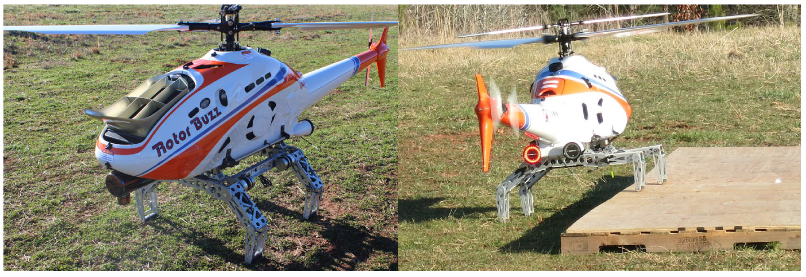
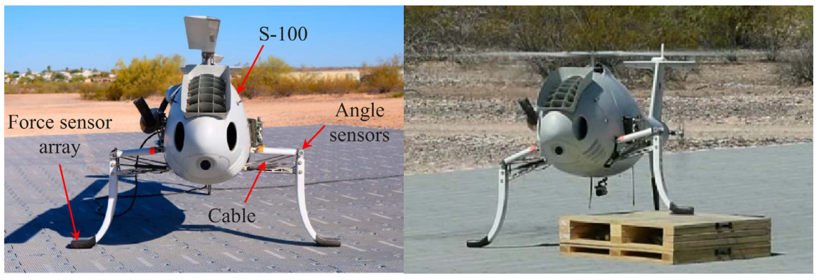
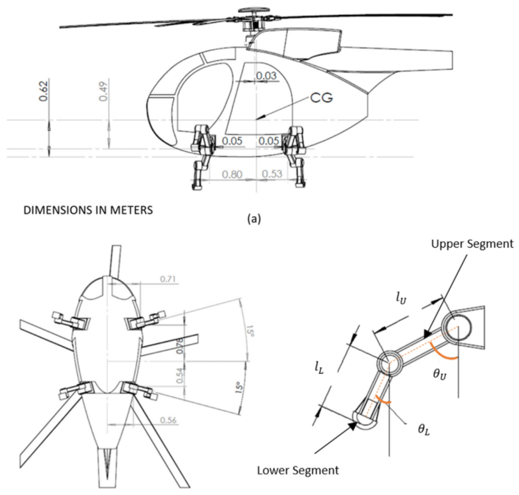
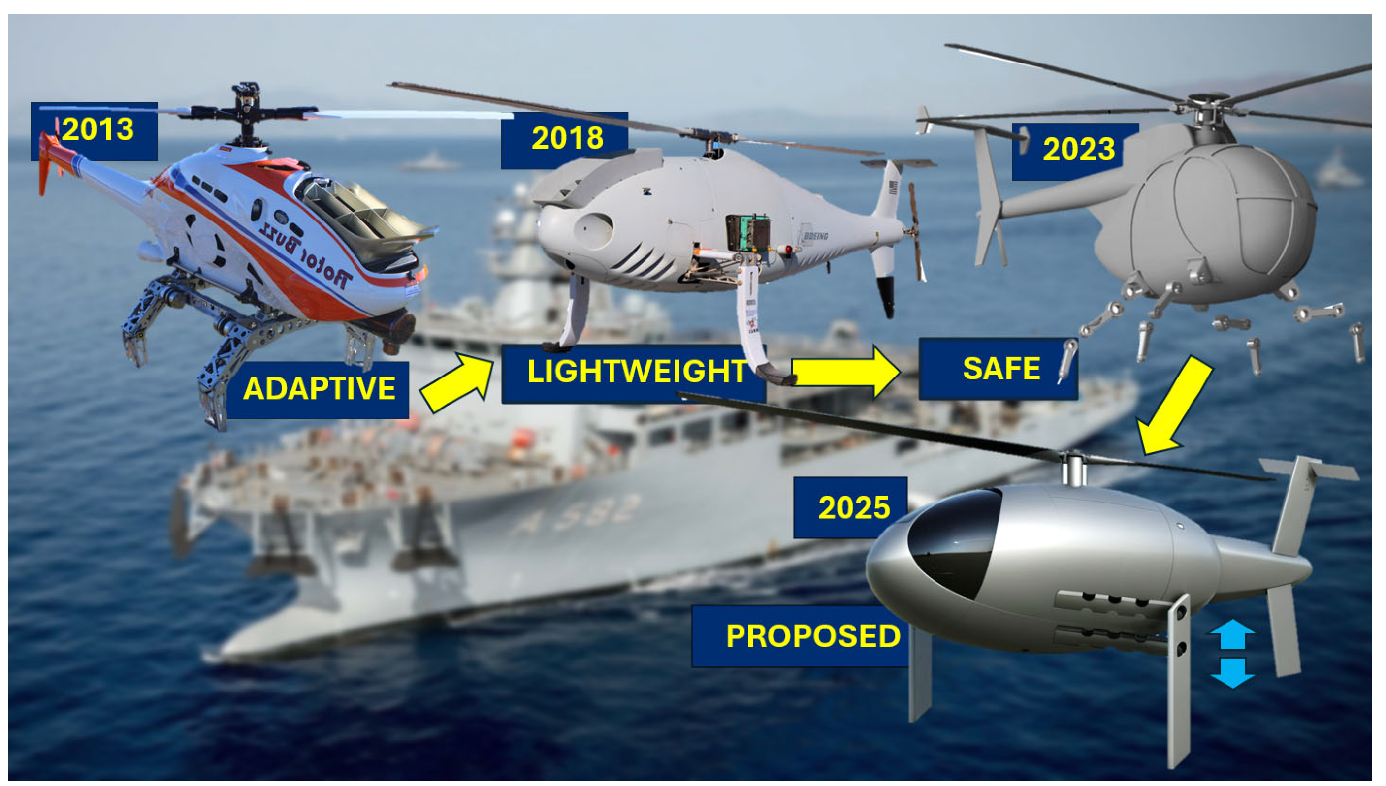
The flexible rotorcraft modeling is based on the floating frame of reference formulation (FFRF) and generalized coordinates, which enables accurate dynamic simulations by considering both rigid and flexible components, essential for ensuring stability and control during landing [
24]. Unlike traditional rigid body dynamics, where components like landing gears are treated as entirely rigid, the FFRF method captures the flexibility of these components, allowing for a more realistic representation of bending deformations. This flexibility is vital for analyzing interactions between the helicopter’s landing gear and uneven terrains, further contributing to stability during landing. An in-depth discussion on the FFRF (
Section 4.3) will be followed by the Dynamics Modeling and Equations of Motion of the helicopter’s flexible landing gear. This elaborates on the derivation of the governing equations, which account for the complexities of both rigid body motion and local deformations of flexible elements. The subsequent Control Strategy
Section 4.4 discusses the implementation of proportional and derivative controllers, focusing on achieving optimal stabilization during landing maneuvers, which the FFRF approach also integrates seamlessly with the system’s control strategy, particularly in relation to roll angle adjustments and overall dynamic stability.
While this methodology provides a robust framework for modeling and controlling the helicopter’s landing gear system, as also mentioned earlier in the previous section, certain aspects, such as hard landing scenarios, contact modeling, and locking mechanisms for post-landing stabilization, are beyond the scope of this paper and are omitted here.
4.1. Static Analysis and System Design
Initial searches in the related literature databases performed by the authors led to examples that focused more on the dynamic aspects of the analysis. However, in landing gear design, static loading is also a highly important loading scenario to consider. Therefore, one should also consider the flexibility of the landing gear frame and components, the landing gear-ground interaction, and the related friction.
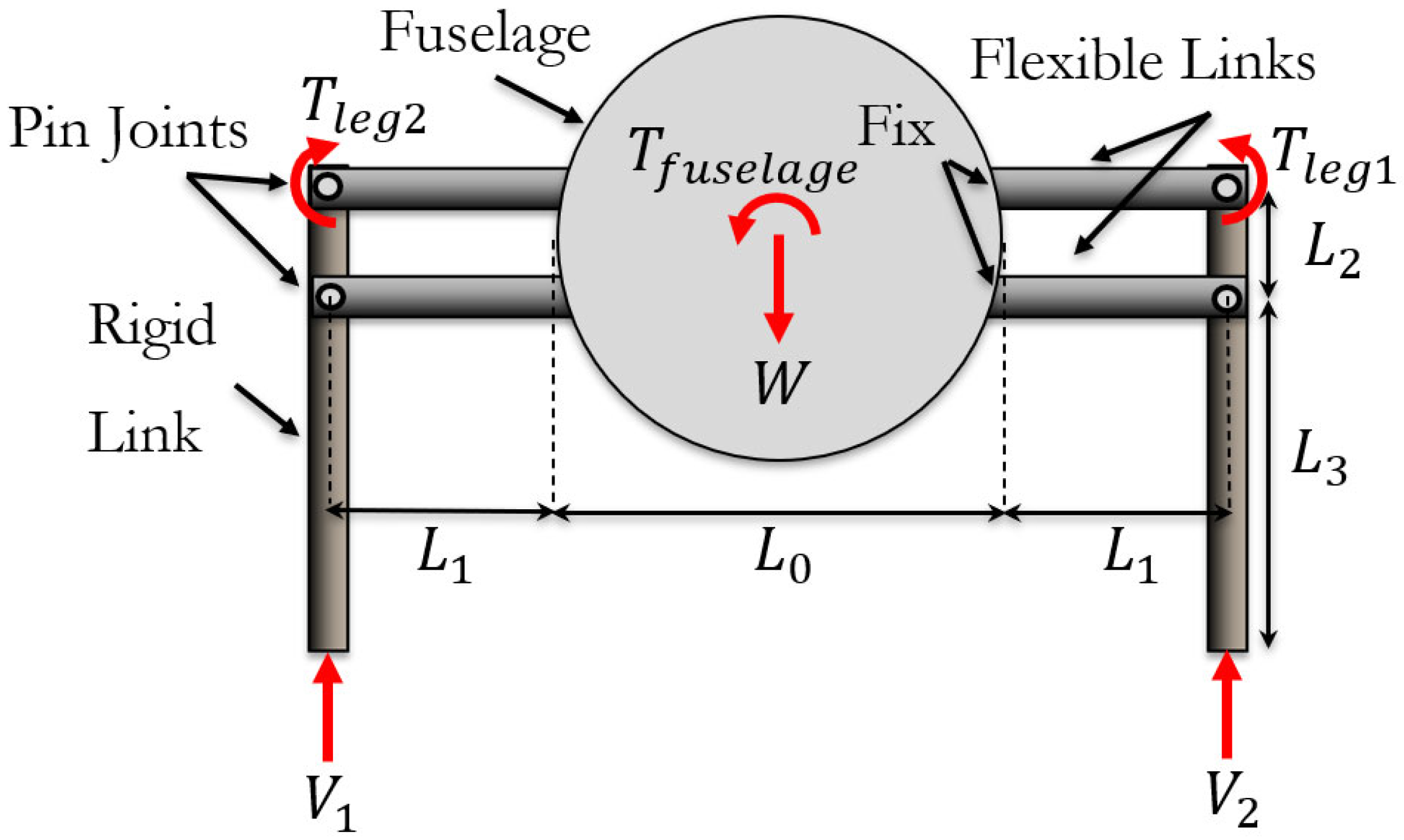
Figure 11 schematically presents an illustrative example of the proposed 2D
hybrid RLG design, and its free body diagram (FBD), incorporating two flexible/compliant mechanisms, flexure hinges, and belt-driven actuation. The middle part, representing the fuselage, is a rigid cylinder with a radius of
and the distance between two legs, or the diameter, is
. Each leg consists of a rigid link and two flexible links, which are modeled as identical Euler–Bernoulli beams of length
, constant bending stiffness
, and a cross-sectional area
. Additionally, the flexible links have a perpendicular distance
between them.
The compliant mechanism presented also has some unique benefits in terms of how loads are distributed across the structure and onto the actuator; a simple static analysis based entirely on static force balances across the structure. Consider first the free body diagram (FBD) of the geometry shown in
Figure 11, where the weight,
, is balanced by two vertical loads,
and
, computed from a sum of forces and moments about the center of the fuselage,
. One notes that the moment arm for
and
with respect to the center of the fuselage varies slightly as the slope angle changes.
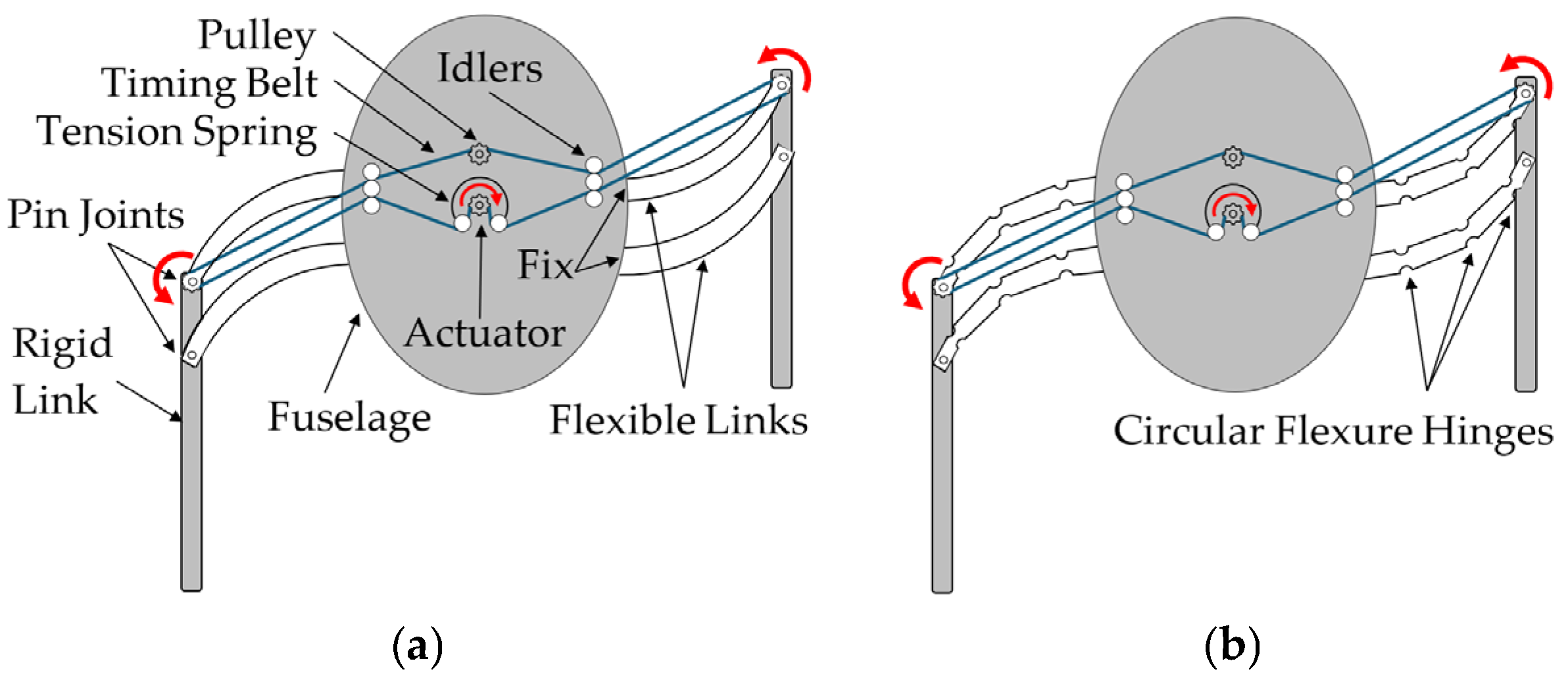
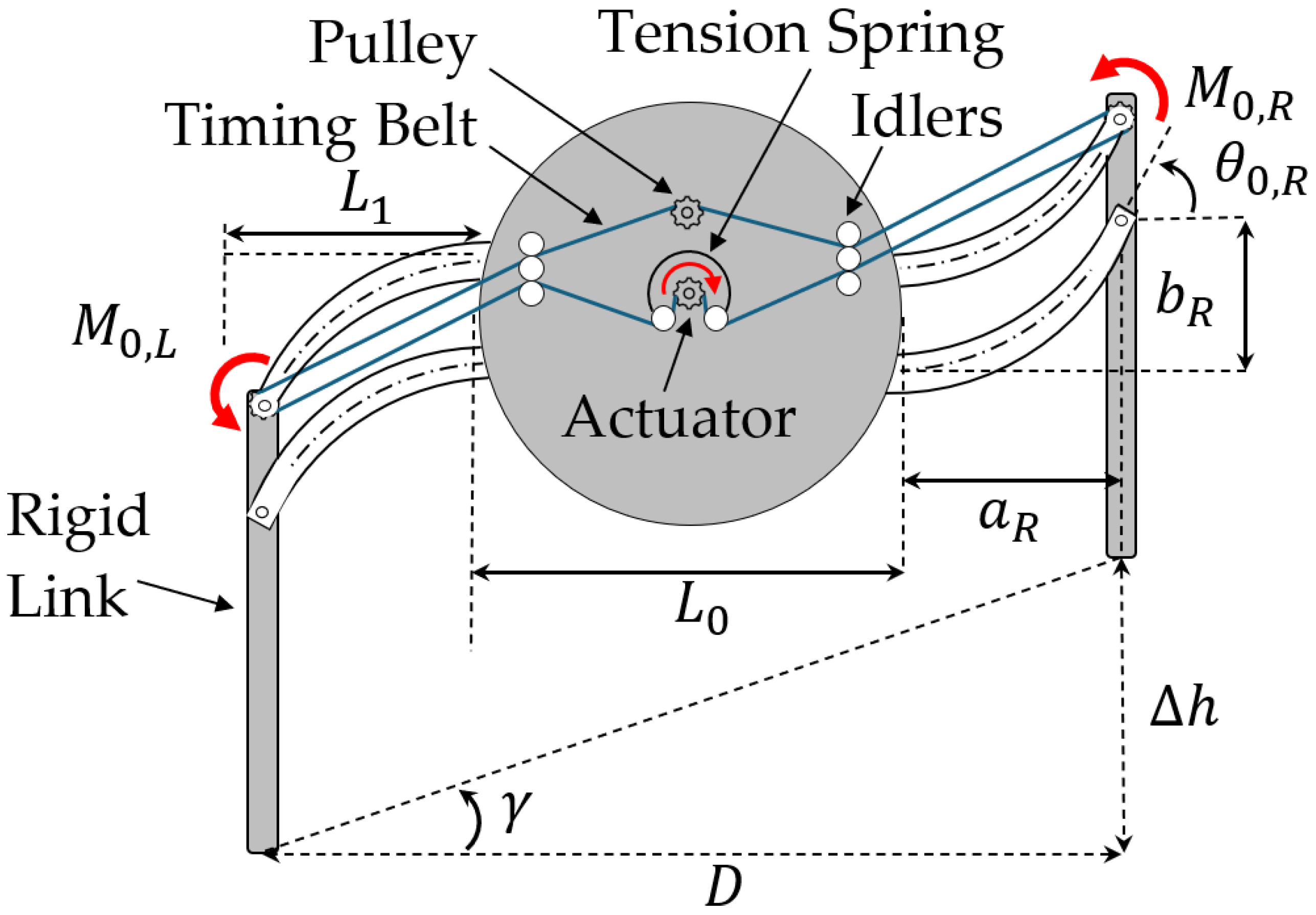
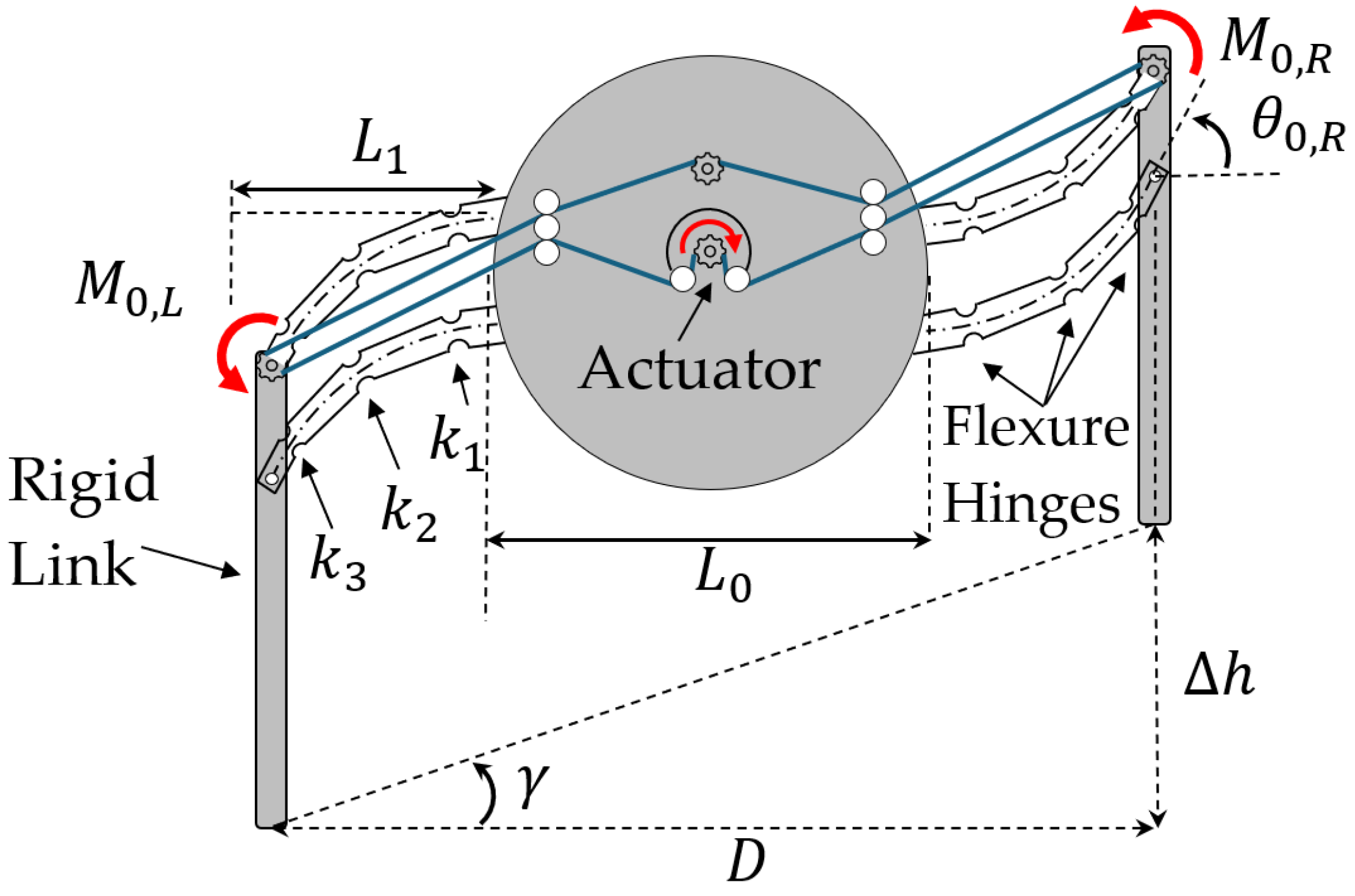
In what follows, a hybrid compliant, four-bar, RLG mechanism design, equipped with two flexible links, as shown in
Figure 12, and a timing belt actuation subsystem, is presented and discussed. Timing belts, also known as synchronous belts or toothed belts, are most often used in transporting, indexing, and positioning applications where high torque or force transmission and high acceleration rates are required. The subsystem includes the timing belts (marked in blue), pulleys, and the actuation components that enable motion (
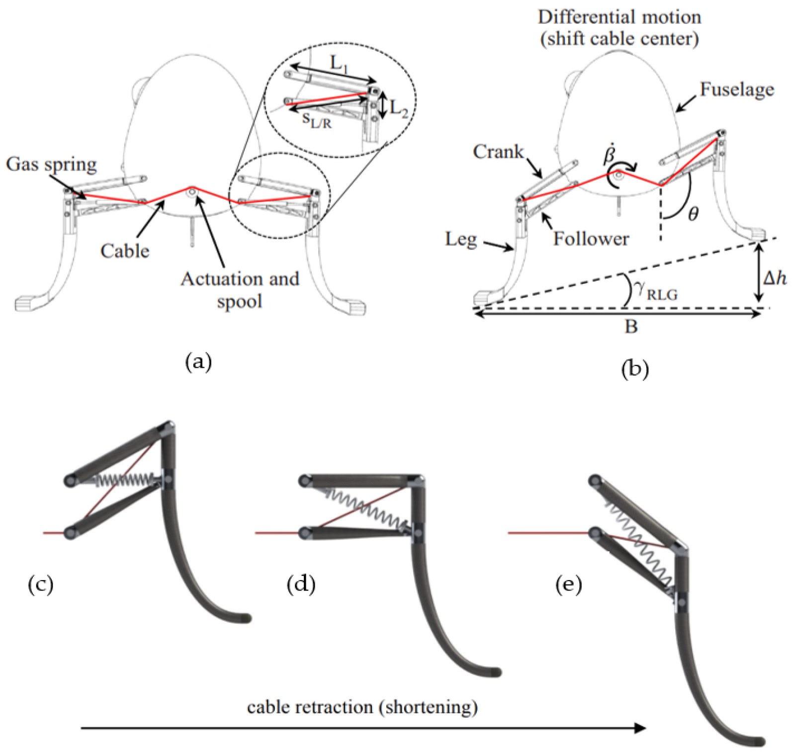
Figure 12). The idler and tensioner are crucial for maintaining the necessary tension in the belts and mitigating belt sag caused by distance changes between the tip and the fuselage. In the proposed hybrid compliant system, the belt-driven actuation has been chosen over a cable-driven system, as proposed by León et al. (2021) [
11] and discussed earlier in this paper, due to its superior performance characteristics such as reduced vibration, lighter weight, and higher torque transfer capabilities, which collectively offer a greater margin of safety.
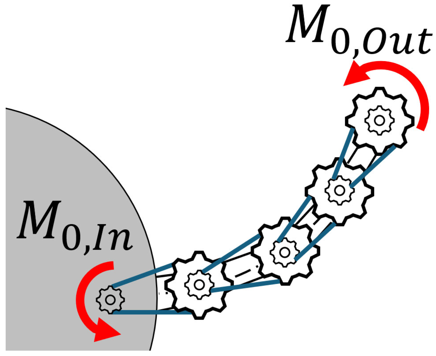
Multiple pulleys of different diameters and tooth counts can be utilized along the flexible leg to achieve a greater output moment,
Mo,Out, at the end, as shown in
Figure 13. This configuration can be customized to amplify the input moment,
Mo,In, to attain the desired moment at the tip while preventing slack in the belts between these points. This concept can also be potentially applied to other variable geometry applications, such as morphing aircraft wings, to ensure effective moment transfer to the wingtip.
This type of mechanism has some unique advantages for the design of actuated robotic legs. Namely, the four-bar nature of the design reduces the robotic landing leg to a single degree of freedom (DOF) system, which in turn reduces the number of the drive system’s components required to actuate each flexible leg. The timing belt’s design allows the actuators to be placed within the fuselage, rather than at joints external to the body, as originally used in the four-legged robotic landing gear (RLG) prototype for the UAV rotorcraft developed by Georgia Tech [
9]. This, in turn, reduces the total number of actuators and the weight of the moving components. From an actuation perspective, coupling the timing belts of two legs also couples their motion.
4.2. Simulation Tests
In contrast to the conventional cable-driven four-bar link method introduced by León et al. [
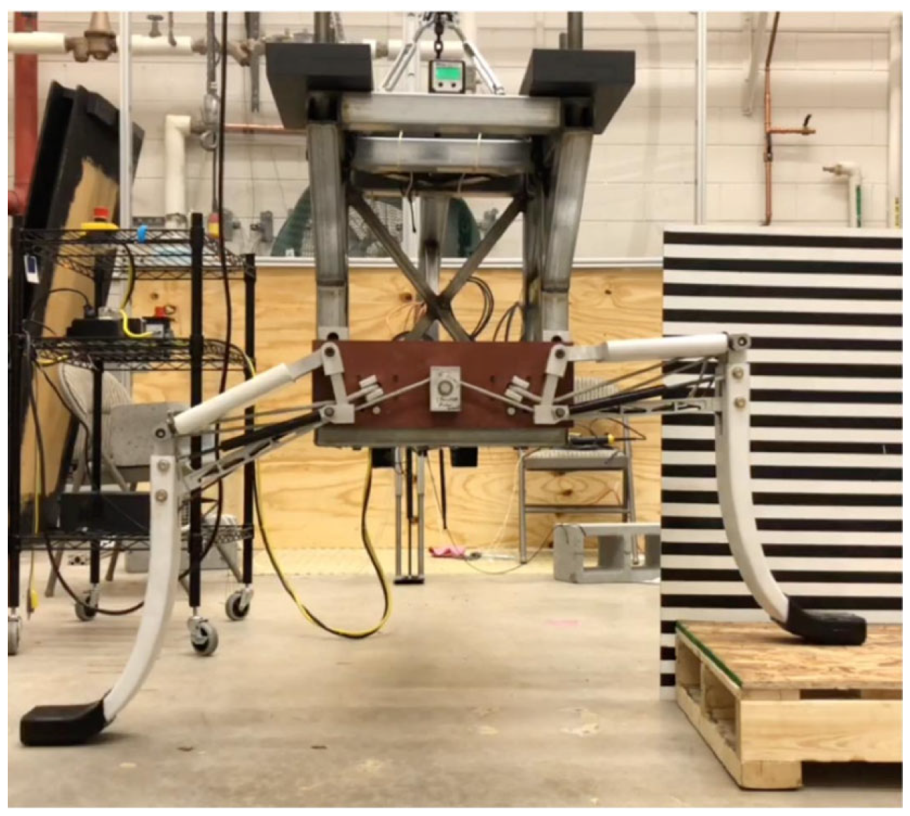
8], which relies on physical articulation tests, the proposed simulation method offers a more efficient and resource-effective approach for testing articulated flexible leg mechanisms. The traditional method involves a complex setup where a crashworthy system lowers the unmanned rotorcraft’s landing gear onto obstacles of heights ranging from 3 to 12 inches (
Figure 14), with both legs locking into a “landed” position upon contact. This requires extensive instrumentation, including a test rig, inertial measurement units (IMU), and various sensors to measure vertical displacement, speed, and leg performance, making it labor-intensive and costly.
The proposed simulation method simplifies this process by focusing on the fuselage’s roll angle instead of rotating the ground or using elaborate mechanical systems. The fuselage is rotated to different angles, and the landing gear’s response is evaluated based on its ability to maintain stability and surface contact. The toe-to-toe (horizontal) distance between the legs,
D, and the slope
, which represents the angle between the two legs with respect to a horizontal reference, are key factors in this analysis, as shown in
Figure 12. While the toe-to-toe distance is taken as constant for simplicity, it can vary slightly during operation.
By focusing on the UAV’s fuselage’s roll angle and maintaining a consistent toe-to-toe distance, this method would potentially offer a cost-effective and simplified experimental setup while still accurately simulating the dynamic behavior of articulated flexible legs. Then, the use of a single IMU to monitor the roll angle further would reduce the need for multiple sensors and actuators, making the system more efficient. This approach would ensure reliable testing and provide valuable insights into the performance of flexible robotic landing gear systems without the need for complex and expensive test setups. The manufacturing of such an experimental setup and the performance of the experimental tests, however, are beyond the scope of this paper.
Regarding the FAA recommendations and ship deck dynamics, rotorcraft operating on sloped or mobile surfaces would benefit from a significant expansion in mission capabilities. This is particularly relevant when considering a single degree of freedom aligned with the aircraft’s roll axis (with pitch, roll, and heave movements similar to those illustrated in
Figure 15a) [
8].
The helicopter–ship landing event simulation incorporates ship motion data to provide a high-fidelity tool for evaluating the complex scenario of a helicopter landing on a ship deck. The wave conditions are specified by the significant wave height, the modal (peak) wave period, and the seaway type (long-crested or short-crested seas). The sea conditions used for the landing simulations are correlated with an accepted sea state code, and the response of the ship to certain sea states can also be varied by specifying the ship speed and ship heading. The sea conditions corresponded to sea state 6 [
1], or the test scenario involved the deck of a German Navy F124 “Sachsen class” frigate proceeding at 40 kt at 30° (green wind) with a significant wave height of
and a peak frequency of
. The resulting maximum motion is a
pitch angle,
roll angle, and
as shown in
Figure 15b [
1].
The simulated results for unmanned rotorcraft landing, as reported by León et al. [
11], are depicted in
Figure 16a, presenting the predictions of an S-100 roll angle response obtained from three simulations. A set of stochastic, varied simulated landings were completed for ground angles γ of 5, 10, and 15° and landing speeds of up to 0.5 m/s (1.6 ft/s). Solid lines represent the average system response, and the same-colored shaded regions represent one standard deviation of the results. Since the feedback controller is not predictive, the simulations show there is an increase in roll angle perturbation as the ground slope increases [
11]. Furthermore, León et al. [
8] validated their simulations through experimental comparisons, showing a close match between simulation and experimental results in terms of contact timing and roll responses during the first 4–5 s. An additional simulation, using sinusoidal platform motion, also confirmed similar trends, reinforcing the value of simulations as reliable tools for characterizing the S-100 RLG system under various landing conditions (see
Figure 16b) [
8].
4.3. Dynamics Modeling and Equations of Motion
The approach to modeling a flexible helicopter within a multibody dynamic framework is centered on the floating frame of reference formulation (FFRF) and generalized coordinates and is tailored specifically to address the inherent flexibility of machine components [
24]. In the context of a helicopter, which comprises rigid and flexible elements like rotor blades or landing gears, adopting FFRF allows for a comprehensive representation of dynamic behavior while accounting for small elastic displacements (crucial for dynamic controls and stability in the landing phase). Unlike traditional rigid body dynamics, where components are assumed to be perfectly rigid, the FFRF method accommodates the deformations and motions of flexible elements (for example, landing gear, in this case) during landing maneuvers.
The use of FFRF involves describing elastic displacements within floating frames attached to helicopter components, offering a practical means to capture complex deformations without overly complicating the model. This approach avoids the limitations of linearized equations of motion encountered in other modeling methods, ensuring a more accurate representation of the helicopter’s dynamics, including both rigid body motions and elastic deformations. By integrating FFRF into the modeling process, the helicopter’s dynamic response to external forces and control inputs can be simulated and analyzed with greater fidelity, providing valuable insights for design optimization and flight performance evaluation. This section elucidates the simulation tools and their integration as a performance prediction model for the RLG. First, the dynamics modeling and governing equations of motion, using a flexible multibody dynamics tool, with a proven track record for RLG development, are described. A 1R Pseudo-Rigid-Body (PRB) model, followed by the system design, simulation, and controls, is then presented. Actuation and resistance calculations for the system at hand are then discussed, followed by a ship deck motion simulation tool and standardized sea state conditions commonly used in similar modeling and analyses.
The dynamic behavior of a 2D VTOL UAV model, equipped with flexible landing gears, is carefully modeled using flexible multibody dynamics (FMD) equations. This approach enables an accurate simulation of the helicopter’s dynamic response, consisting of two major components: (a) the fuselage, modeled as a 2D rigid body with a uniform mass distribution, and characterized by its mass moment of inertia about the center of mass, and (b) two flexible landing gear legs, which exhibit elastic deformation during dynamic interactions, such as landing.
Key parameters must be defined to model the system accurately, including the length, density, cross-sectional area, modulus of elasticity, and moment of inertia of the landing gears. These parameters influence the overall stiffness, flexibility, and inertia properties, which are critical in determining the dynamic response of the system during landing.
Referring to
Figure 11 and
Figure 12, when the relative difference between the beams’ length (
) and perpendicular distance between them (
) is not large enough to significantly impact the moment of inertia of the fuselage, they can effectively form a single composite virtual beam, doubling both the second area moment of inertia (
), and the cross-sectional area
), while maintaining the same length,
.
This simplification reduces the computational complexity of the model while still accounting for the flexibility of the legs. Once the overall dynamics are calculated, the legs are discretized again for detailed analysis. More parallel beams could also be added, where the set of compliant members could be virtually represented by an equivalent (i.e., composite) single beam. Then, the equivalent properties can be obtained by multiplying the individual beam’s parameters (second area moment of inertia and cross-sectional area) by the number of beams. This would further simplify the model while still accurately reflecting the added stiffness and flexibility of multiple parallel legs.
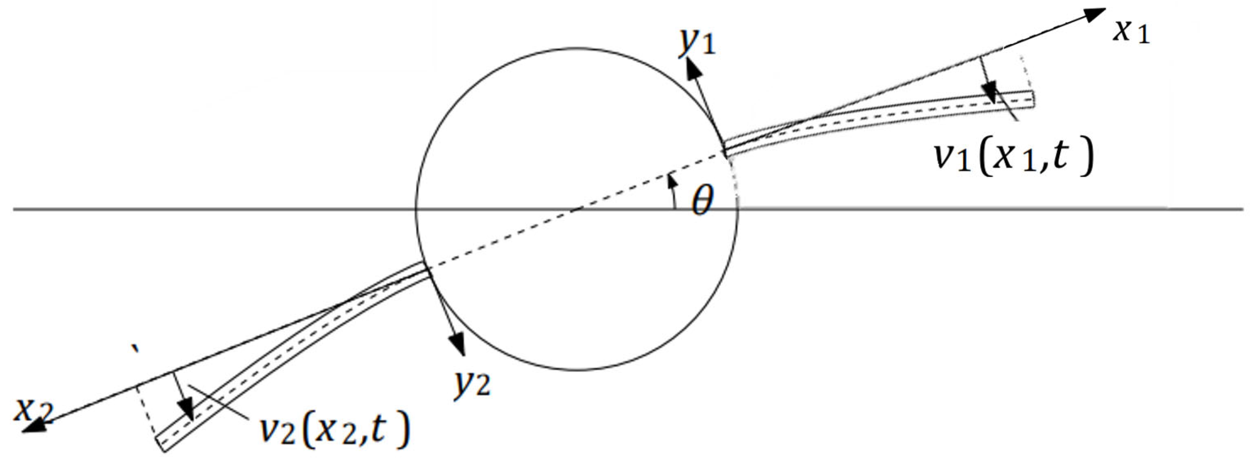
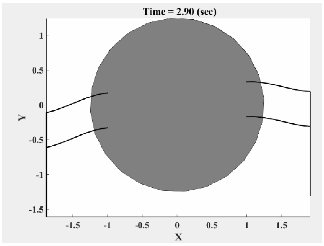
A VTOL UAV body with two virtual composite flexible/compliant legs on one axis is illustrated in
Figure 17. The middle part, or the fuselage, is assumed as a rigid cylinder with radius
, uniform mass properties, and a mass moment of inertia,
, around the center axis. The two elastic or flexible links are modeled as identical Euler–Bernoulli beams with length
, constant mass density
, and constant bending stiffness
, where
is the second area moment of inertia of each flexible links, and
is the cross-sectional area of each beam. The Euler–Bernoulli beam theory assumes slender, long beams where cross-sectional deformations are negligible, and deformation is primarily due to bending [
25]. This theory, suitable for fixed-free boundary conditions, enables accurate modeling of the legs’ bending behavior.
In the case of robotic landing gear, the flexible legs undergo bending deformation due to forces exerted during landing and takeoff. Let
and
be the lateral displacement due to flexible motion of each leg shown in
Figure 17, where
and
are coordinates along the respective beams, measured from their attachment points on the fuselage.
The deflection of each flexible landing gear leg,
, as expressed in Equation (1), includes quadratic (
) and cubic (
) terms. These terms arise from the Euler–Bernoulli beam theory, which models the bending of slender beams while neglecting rotary inertia and shear deformation [
26]. These higher-order terms capture the curvature and bending behavior under the assumption of small elastic deformations.
Using the Ritz method and the generalized equations of motion for a continuous system, the displacement field
may be approximated by [
24]
The shape functions,
, and set of generalized coordinates,
, are assumed as
The generalized coordinates,
, consist of the reference coordinates (rigid),
and elastic coordinates,
, respectively. The differential equations of motion of the multibody system can then be written as
where
is the vector of generalized forces that arises from differentiating the kinetic energy with respect to time and with respect to the generalized coordinates of the rigid central body:
where
is the rotation matrix,
is the total force acting on the body (resolved in the inertial frame),
represents the total torque on the undeformed body (resolved in the body frame), for small elastic deformations,
is the incremental torque acting on the deformed body due to elastic deformation (resolved in the body frame), and
is the generalized force acting on the elastic coordinates [
27].
The expressions for the potential energy,
, stiffness matrix,
, energy of external forces,
, and the generalized forces acting on the elastic coordinates are written as
where
E is the matrix of elastic moduli for an isotropic material. The kinetic energy of the system, T, consists of contributions from the fuselage and both legs:
Expressions for the components of total kinetic energy, T, are as follows:
knowing the mass matrix,
, is defined as [
24]:
The system’s overall (total) mass matrix,
, consists of contributions from the
,
, and
mass matrices, defined as follows:
where
and
represent the shape symmetric matrices of the first and second legs,
ρ is the material density, and the mass moment of inertia,
.
Then, the mass matrices for leg 1,
, and leg 2,
, are given by
The potential energy of the system,
, is expressed as
where
E(
x) is the matrix of elastic moduli, and the stiffness matrix,
, is defined as
One can use the shape function
to form the stiffness matrix for the first composite compliant leg.
where
and the shape function
to form the stiffness matrix for leg2,
where
4.4. Control Strategy
In this paper, the VTOL UAV landing gear’s position and control were managed through proportional-derivative (PD) controllers, applied to a linear dynamics model of the system. While PD control is typically used for linear systems, it can still effectively regulate the motion of the RLG by adjusting the proportional and derivative gains. This approach ensures that the helicopter maintains stabilization during landing, including under varying ship deck conditions. The compliant robotic landing gear system is defined by a set of five state variables, representing the angular orientation and positions of its flexible legs. The initial positions of the system are given by the following vector:
where
represents the initial angular orientation of the fuselage of the helicopter, while
and
correspond to the positions and curvatures of the right flexible leg. Similarly,
and
represent the positions and curvatures of the left flexible leg. These initial values reflect a symmetric starting condition where both legs are pre-configured with initial curvatures, preparing the system for controlled descent and landing, while the initial velocities of all state variables are set to zero.
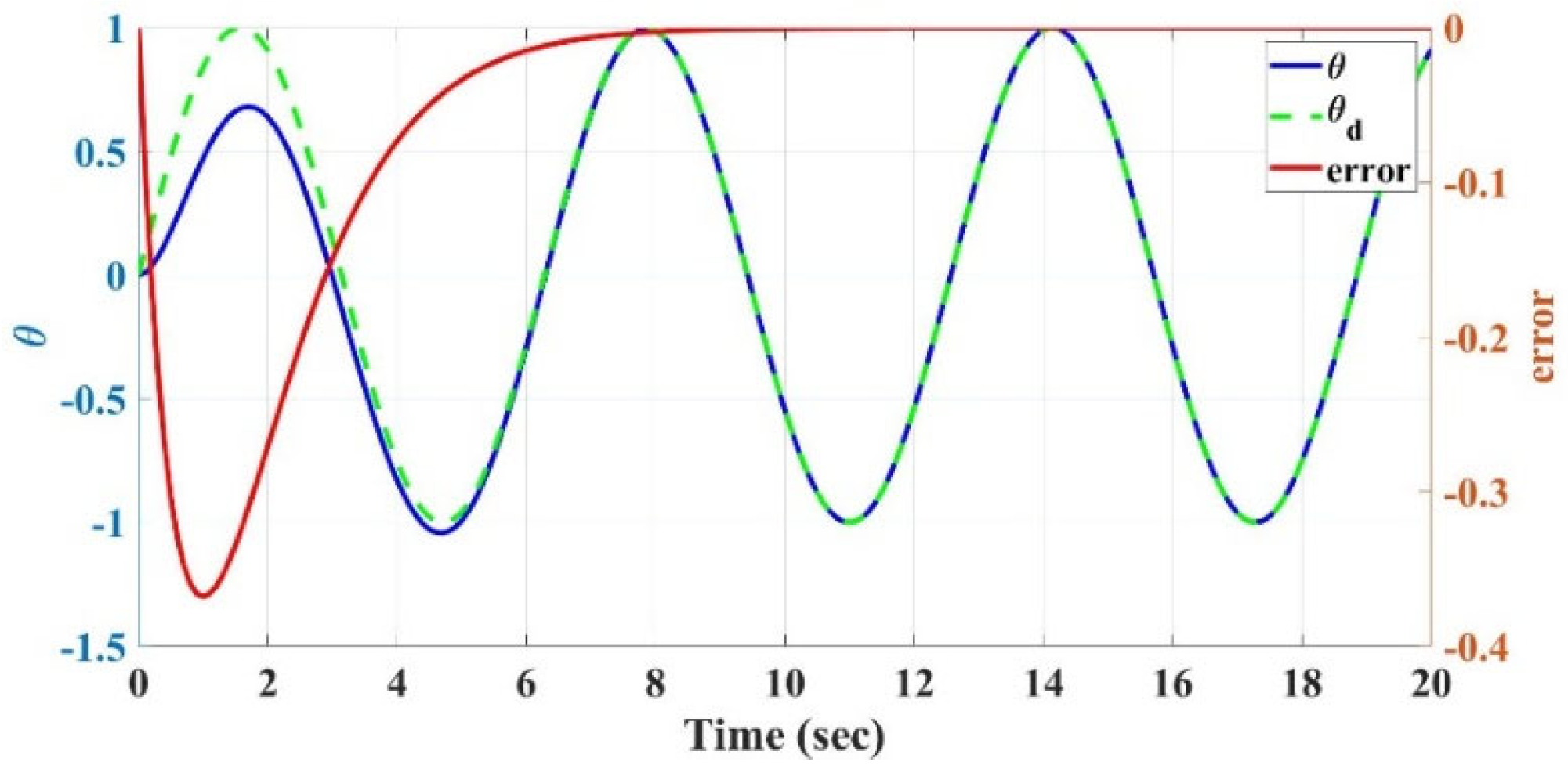
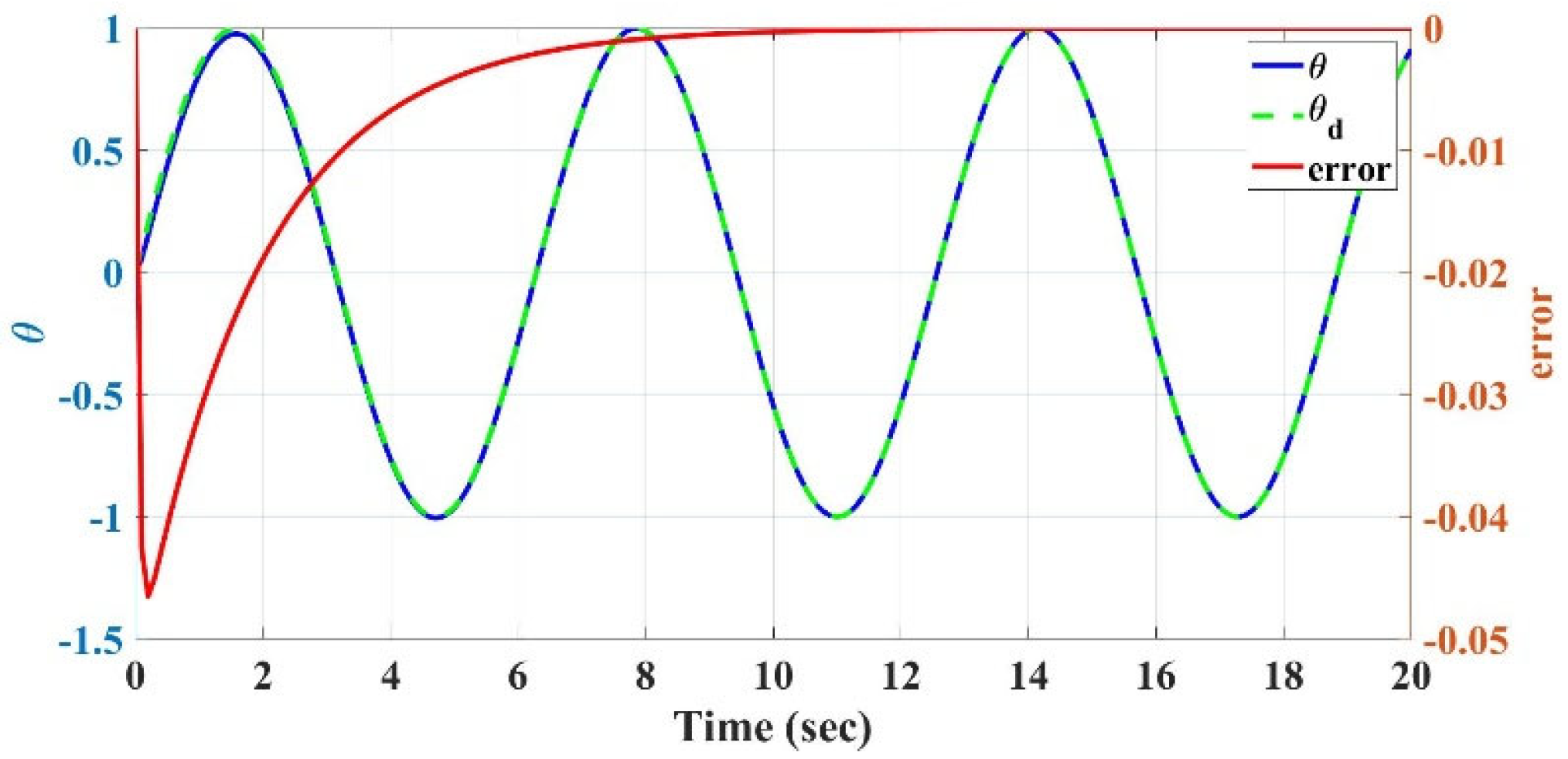
The control inputs for the flexible robotic landing gear are designed based on the error between the actual and desired positions of the landing gear. The control system aims to regulate the fuselage roll angle, θ(t), ensuring that the landing gear follows a desired trajectory. The control strategy accounts for both the roll angle error, , and the rate of change in this error. The desired roll angle, , is defined as a sinusoidal function:
The control law used to stabilize the system is given by
is the total moment of inertia about its center of mass (fuselage plus landing legs).
is the reference roll angle.
is a derivative control gain.
is a proportional control parameter.
is the error between the actual roll angle and the desired roll angle.
Additionally, the reference roll angle velocity
is updated according to the following rule:
where
is the rate of change in the desired roll angle, which for
is
is a tuning parameter in the control law that scales the impact of the roll angle error,
, on the desired rate of change. The parameter
acts as a proportional gain, ensuring that the control response is sensitive to discrepancies between the actual and desired roll angles.
This control law ensures that the roll angle of the fuselage, , tracks the desired sinusoidal trajectory by continuously adjusting the control input . The derivative term stabilizes the system, minimizing oscillations and ensuring smooth behavior. Here, is a derivative control gain, which regulates the system’s response to changes in the error signal. By appropriately tuning , one can control the rate at which the error is driven to zero over time, ensuring that the actual roll angle converges to the desired trajectory.
This approach allows the compliant robotic landing gear to perform controlled landings by dynamically adjusting the system’s behavior based on real-time feedback from the fuselage’s roll angle and the desired trajectory. The simulation runs for 20 s to demonstrate the stability and effectiveness of this control mechanism in guiding the landing gear.
4.5. Pseudo-Rigid-Body (PRB) Model
Building upon the modeling of compliant legs using cantilever beam equations, this study employs the Pseudo-Rigid-Body (PRB) model to simplify the deflection behavior of flexible elements into a more manageable and predictable framework. Specifically, the single revolute (1R) PRB model is utilized to estimate the allowable error bounds for beam tip deflections.
The PRBM approach bridges the gap between compliant mechanisms and rigid-link designs by approximating the behavior of flexible elements using kinematic trajectories and force–deflection relationships. The PRB 1
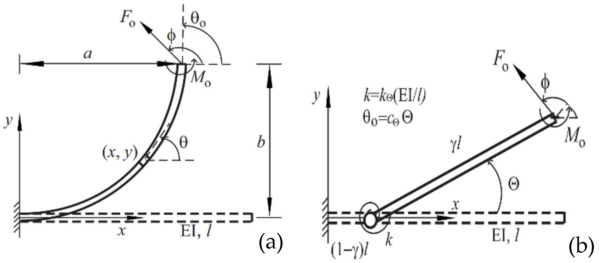
R model shown in
Figure 18b consists of two rigid links connected by a pin joint and a torsion spring. The location of the torsion spring from the origin is determined by the characteristic radius factor,
, and the horizontal and vertical positions
of the tip point are determined by a
Pseudo-Rigid-Body (PRB) angle,
[
28]. In
Figure 18a,
is the angle between the horizontal and the beam’s longitudinal axes.
In practical designs, the slope angle is often limited by the maximum stress of the beam, happening at the fixed end for a beam with monotonic curvatures. To prevent the beam of a rectangular cross-section from failure, the condition of , where , with the applicable/intended safety factor (S.F.), must be satisfied. Here, is the material yield strength, is the allowable stress, and is the height of the cross-sectional area. For the purposes of this design, the safety factor has been set to 1 for optimization (i.e., ), though this value can be adjusted depending on the specific requirements and design preferences of the engineer.
To determine the maximum slope angle,
, Su [
29] introduced a beam slenderness ratio of
, and a material flexibility of
into Equation (23) below:
The larger these two quantities, the larger slope angle the beam can be bent to.
The right side of Equation (23),
and
, represents the normalized and the dimensional net moment applied to the fixed end of the beam, respectively, where
.
The 1
R model Expression (25) below shows the characteristic radius factor,
, the parametric angle coefficient,
, and the stiffness coefficient,
(refer to [
28]).
where
a is horizontal tip deflection and
b is vertical tip deflection (
Figure 18), and the normalized tip deflection
, can be found using Equation (26) from the tip slope angle,
, utilizing parameters from the optimal PRB 1
R model Equation (25), as reported by [
28]:
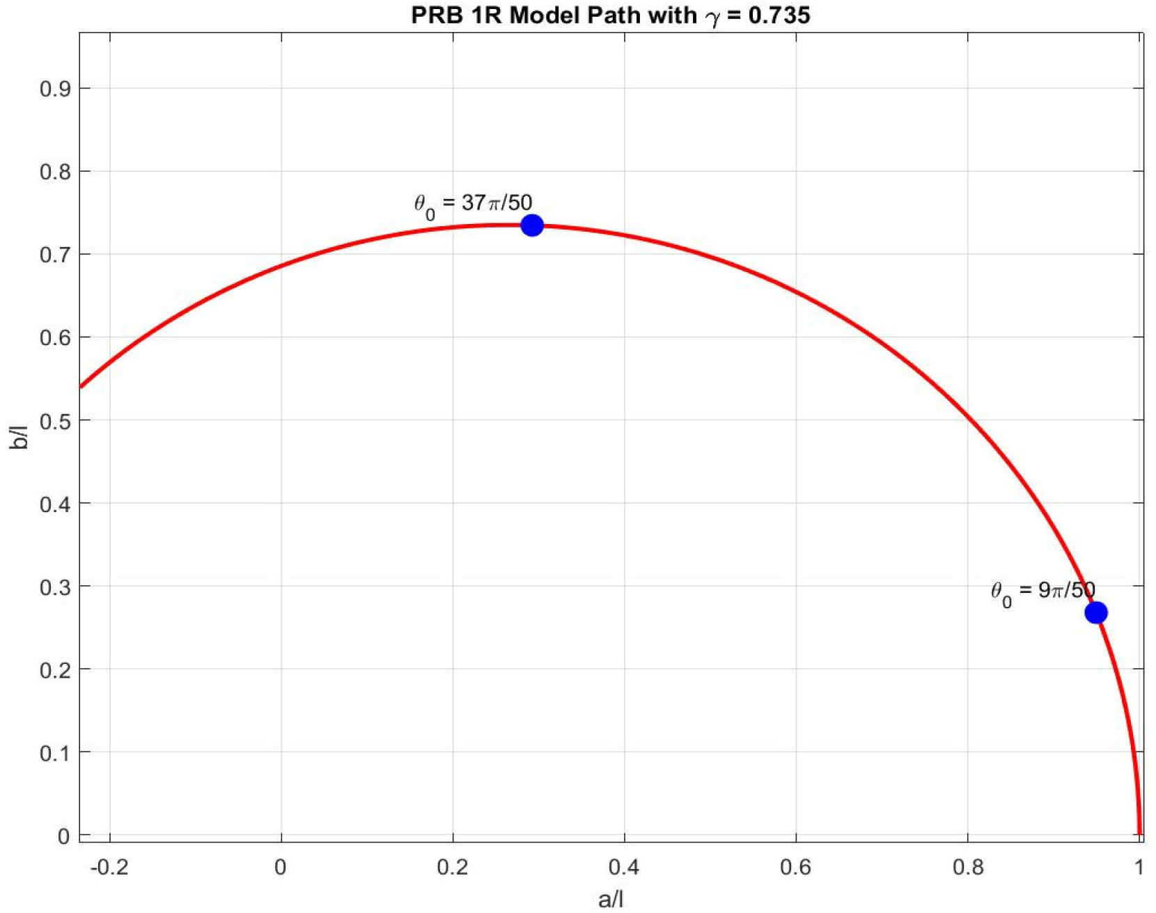
Figure 19 below illustrates the tip deflection of the PRB 1
R model path with specified parameters and markers for
.
4.6. Resistance and Actuation Calculations
In what follows, the pertinent structural and actuation subsystems, for the proposed
hybrid, compliant, four-bar, VTOL UAV RLG system, are briefly discussed. These subsystems include the structural mechanism, timing belts (marked in blue), pulleys, and the actuation components that enable motion, as shown in
Figure 12. The idler and tensioner are crucial for maintaining necessary tension in the belts and mitigating belt sag caused by distance changes between the tip and the fuselage.
As also mentioned earlier, a belt-driven system has been chosen over a cable-driven system to actuate the two flexible four-bar leg mechanisms, due to the advantages, such as reduced vibration, lighter weight, and higher torque transfer capabilities, collectively offering a greater margin of safety.
Consider a system with two sloped legs where the belts connect on a center gear, as shown in
Figure 12. This configuration enables symmetric-differential leg motion, with one leg moving up while the other moves down. Referring to
Figure 12, the vertical displacement or the deflection of flexible right link,
, and the tip horizontal position,
, the right leg position, caused by the external moment,
, at the tip of the flexible link, can be calculated as function of the link length,
, and the tip slope angle,
, from Equation (27):
using the parameters,
as given in Expression (25).
In the symmetrical leg movement, the position of the left leg would be of the same magnitude but in the opposite direction of the right one (i.e., ). Then, the total vertical displacement is: , and in the symmetric case, .
The total leg spread
D is given by:
, where
Thus, in the symmetric configuration:
, using the leg positions determined through Equation (27), the ground angle
can be calculated using Expression (23) below:
To identify the material and beam slenderness ratio of the flexible links, l/t, while sustaining without failure under a pure moment load (i.e., maximum stress), one should consider the maximum ground angle and vice versa. Equation (28) shows that the maximum ground angle is related to the length of the beam and the max tip slope angle, . Due to the design limit, (l/t)max= 100 for the materials of choice (aluminum (7075)/titanium Ti-13), as discussed earlier in this paper. The tip slope angle calculated for a beam made of titanium (Ti-13) is 115 deg, and for a flexible link made from aluminum (7075) it is 80 deg. By setting these maximum slope angles for each material and considering and , one can then calculate the maximum achievable ground angle for the RLG design. For a flexible leg mechanism (where , using flexible links made from titanium (Ti-13) would lead to a maximum ground angle of 26.57°. However, if aluminum (7075) construction is used, the flexible leg mechanism can be bent to achieve a ground angle of 19°.
The ratio of
(allowable stress over the modulus of elasticity) is used to determine the maximum weight that fuselages can safely sustain when supported by flexible legs mechanism made of Ti-13 or aluminum 7075, under pure moment loads (determined by maximum stress). For these materials, the flexibility ratio (
) of Ti-13 to aluminum 7075 is 10/7, reflecting their respective material flexibilities [
30]. Ti-13 demonstrates higher flexibility compared to aluminum 7075.
To determine the net moment required to bend the beam and reach maximum stress, the dimensional moment from Equation (23) is used, knowing the beam’s length, , thickness, , width, , and modulus of elasticity, . For Ti-13 and aluminum, a large moment is required to sustain substantial fuselage weights. However, one may calculate the allowable fuselage weight, should a different material be used. For example, a flexible leg mechanism made of polypropylene would support a much lighter fuselage weight when subjected to similar conditions, due to its much lower elastic modulus.
Finally, by examining the relationship between the forces
,
,
(acting on the leg), and the moment applied at the fuselage’s center (leading to a symmetric movement), the net moment for each flexible link (beam),
can be derived using the following equation:
This equation highlights the relationship between the net moment, the beam’s geometry (
l,
t,
w,
L0, and
L1), material properties (
E, and
), and the weight of the system,
W, providing crucial insights for optimizing the structural performance of flexible landing gear.
4.7. Compliant Mechanism: Design Optimization
In recent years, compliant mechanisms have gained significant attention as a viable alternative to traditional rigid body systems connected by conventional pin joints, especially in the creation of machine tools for small-scale applications. Unlike traditional mechanisms, compliant mechanisms are flexible, monolithic structures that derive their motion from the elastic deformation of certain parts, known as flexure hinges. This unique characteristic of compliant mechanisms provides several advantages over conventional mechanisms,
consisting of rigid links connected through revolute joints. These advantages include, but are not limited to, enhanced accuracy and reliability, along with lower wear, backlash, maintenance, and weight, accomplished through topology optimization and advanced manufacturing methods [
31].
A prominent example is circular notch hinges (
Figure 20, adapted from [
32]) formed by machining symmetrical circular patterns along each side of a beam, resulting in a slender, flexible path between two rigid segments. These notched flexures are nearly 100% efficient during assembly, offering a notable advantage over traditional leaf flexure hinges. Optimizing the geometry parameters of circular flexure hinges, thickness (
t), radius (
R), and width (
w), further contributes to the overall system optimization, as each enhancement in hinge design positively impacts the entire design process.
In a recent publication by Kabganian and Hashemi [
12], a new accurate compliance/stiffness equation for
t/R ranges of 0.2 to 0.8 was introduced, targeting improved modeling accuracy for torsional stiffness and rotational compliance
in circular flexure hinges (CFHs). Utilizing a hybrid PRBM-FEM approach, this model achieved improved accuracy in flexure hinge representation, resulting in the following empirical stiffness Equation (30):
where the coefficients
originally determined and reported in the authors’ earlier publication [
12], are presented in
Table 1 below. Additional parameters are illustrated in
Figure 20.
The current study adopts Equation (30) to improve design accuracy and minimize error in compliant mechanism applications, balancing simplicity in manufacturing with a safe, controllable design. By enabling precise control of torsional movement, this approach enhances system reliability—a critical factor for controlled performance.
4.8. Optimal 3-SFH Using the PRB Model
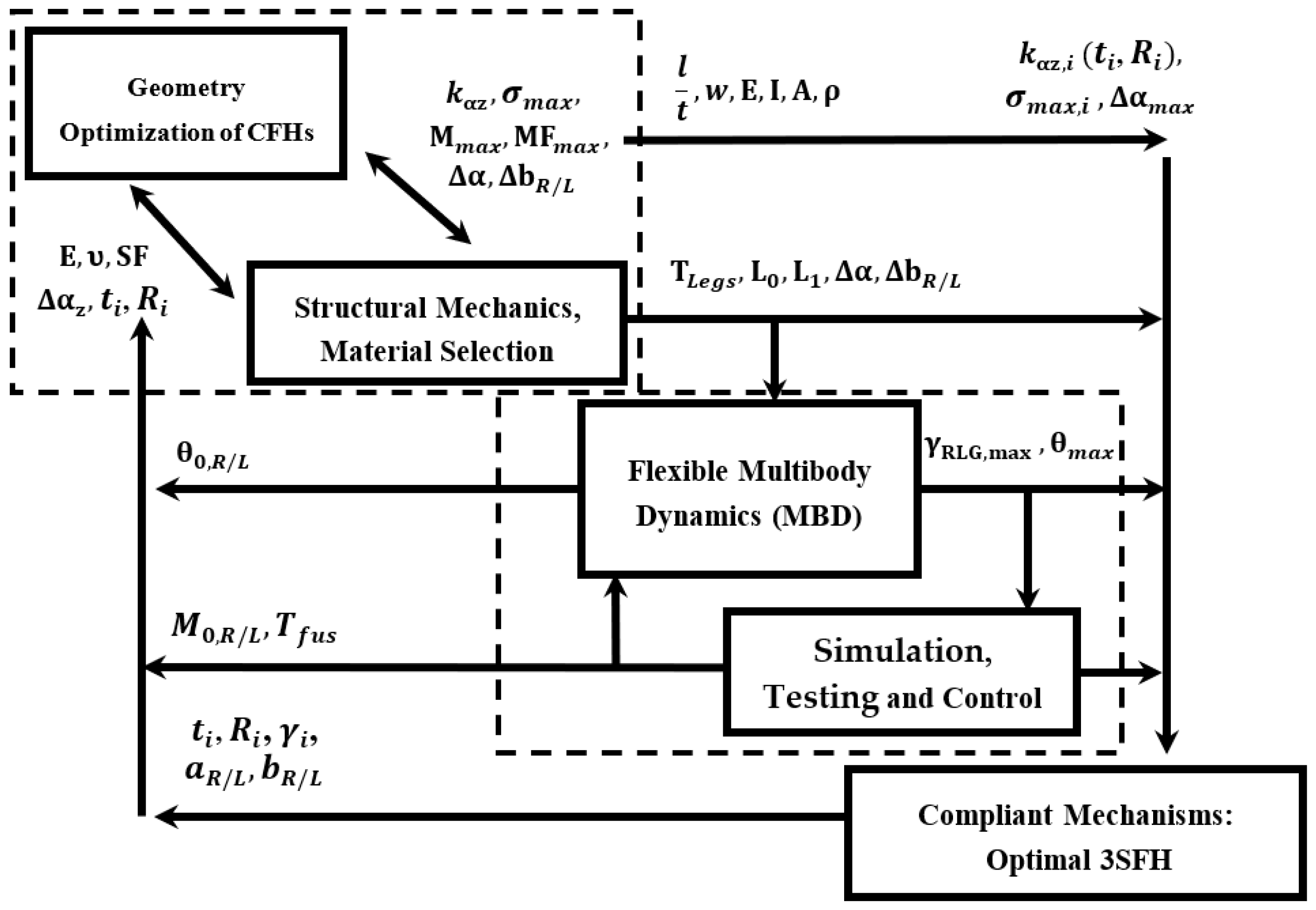
After determining the net moment applied to the fixed end of the cantilever beams and its relationship with the slope angle, the optimal design of circular flexure hinges (CFHs) is achieved using the kinostatic (kinematic and static) equations, as derived and presented by Su [
29] for cantilever beams subject to tip loads. Optimizing the geometric parameters of circular flexure hinges, i.e., thickness (
t), radius (
R), and width (
w), is crucial for enhancing the performance and reliability of compliant mechanisms. As shown in
Figure 20 (adapted from [
32]), these parameters significantly influence the mechanical behavior and structural integrity of the hinges.
Building on the compliance/stiffness Equation (30), the present study uses the modeling of torsional stiffness and rotational compliance () in CFHs. Utilizing a hybrid PRBM-FEM approach, Equation (30) was developed which is accurate for t/R ratios ranging from 0.2 to 0.8. The enhanced flexure hinge representation enables precise control of torsional movement and improved system reliability, i.e., a critical factor for controlled performance in compliant mechanisms.
Based on the earlier modeling and analysis of compliant legs using cantilever beam equations presented earlier in this paper, in what follows, the extension to the design and optimization of three-series flexure hinge (3SFH) compliant legs [
29], incorporating the Pseudo-Rigid-Body (PRB) method, is presented. The focus here is on the design optimization of circular flexure hinges through an accurate analytical model with variable parameters, as presented in an earlier work by the authors [
12], aimed at assessing compliance and rotational precision under various loads. These efforts are directed at enhancing the design of compliant legs equipped with circular flexure hinges, which have demonstrated accurate performance as torsional springs. The PRB 3
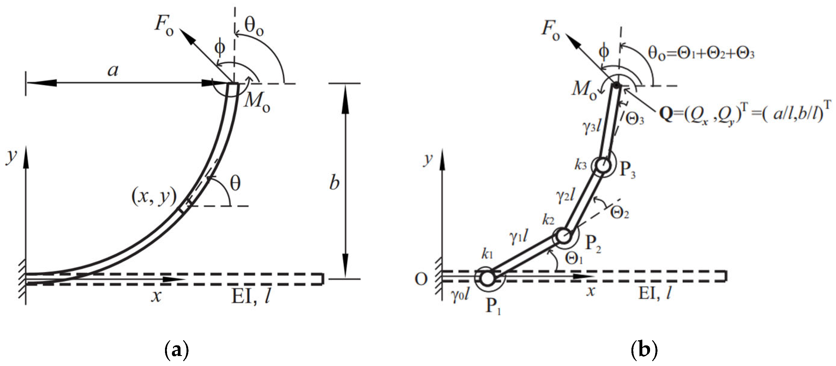
R model shown in
Figure 21 (right) consists of four rigid links connected by three pin joints and three torsion springs [
12], necessitating the calculation of compliant stiffness specific to the circular flexure hinges [
29]. For the 3
R model, the deflection angles and spring stiffness in
Figure 20, right, are denoted by
,
, and
and
,
, and
, respectively. The ratios of the length of each bar to the total length of the system are characteristic radius factors, denoted by
,
,
, and
, summing up to 1.
Considering the initially straight, continuous, cantilever beam (a) and the articulated PRB 3
R model (b),
Figure 21 shows deflections when the system is subjected to external tip loads of
and
. The direction of the end tip force,
, with respect to the
x-axis is denoted by the angle
. The parameters
,
, and
are the tip slope angle and the horizontal and vertical tip deflections, respectively.
and
are the nondimensional force index and load ratio, respectively, defined as [
29]
The position of the tip point is
, where
and
are the normalized tip deflection, and the slope angle,
, of the 3
R chain is calculated as
The torque values at the three pin joints are given by
where
, and
. The matrix
is the transpose of the nondimensional Jacobian of the 3
R chain obtained by differentiating kinematic Equation (32), written as
where
. Assuming the spring torques are proportional to the PRB angles, i.e.,
the spring stiffness,
, can then be normalized to
By substituting definitions (35) and (36) into (33), the normalized and nondimensional statics equation is obtained as
where the definitions (31) are used.
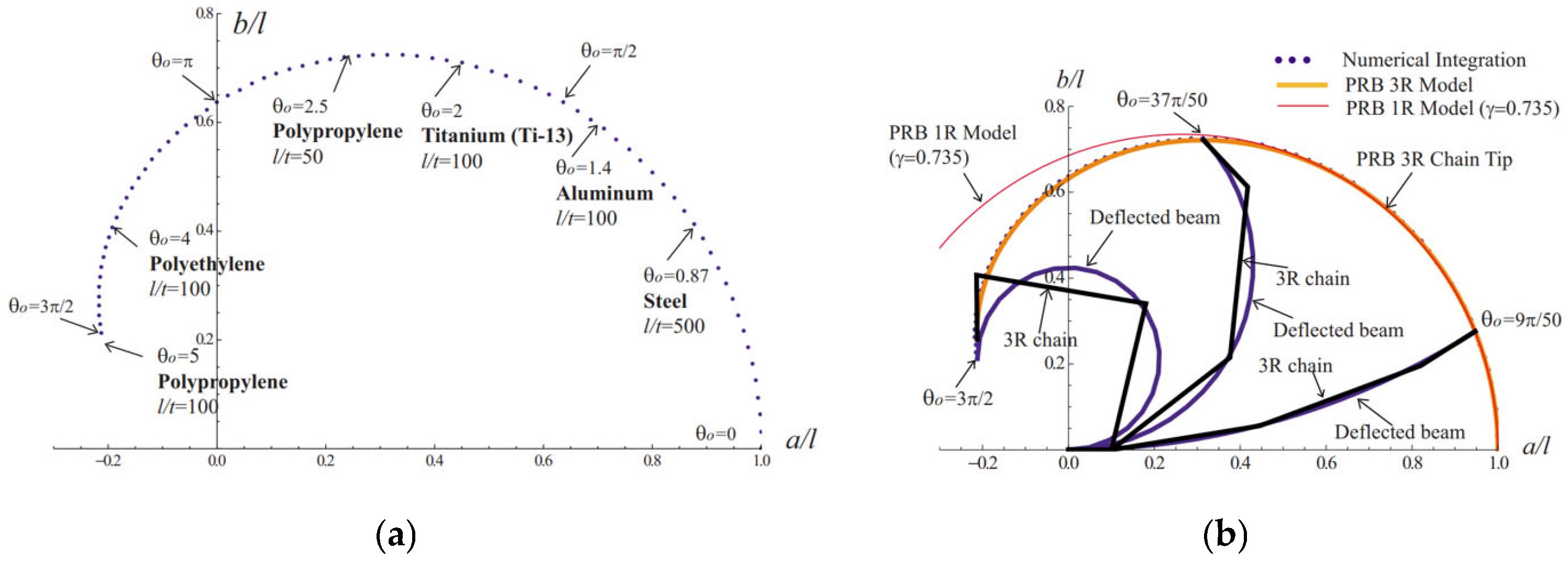
Figure 22a illustrates the fail-free, achievable tip slope,
, for a flexible beam subjected to a tip moment, influenced by the beam’s material properties,
E, and slenderness ratio,
. The values of the
l/
t ratio for various materials are from Reference [
30]. As can be seen in
Figure 22, titanium (Ti-13) and aluminum (7075) beams with
l/
t = 100 can sustain a tip bending angle of 2 rad (115°) and 1.4 rad (80°), respectively, without failure, whereas a steel (4140) beam of
l/
t = 500 can only be bent to an angle of 50°. A PRB 3
R model for determining the large deflection of cantilever beams subject to tip loads was presented by Su [
29] on the system’s geometric parameters and spring coefficients and showed that they are independent of external loads. The comparison between 1
R and 3
R can be seen in
Figure 22b. The implementation of these concepts in the development, analysis, and optimization of the proposed hybrid compliant RLG system, and the relevant results, will be reported later in this paper (refer to
Section 5).
