Article

Real-Time TECS Gain Tuning Using Steepest Descent Method for Post-Transition Stability in Unmanned Tilt-Rotor eVTOLs

1
Department of Convergence Engineering for Intelligent Drone, Sejong University, Seoul 05006, Republic of Korea
2
Institute of Mechanical and Electrical Engineering, University of Southern Denmark, 6400 Seonderborg, Denmark
3
Department of Drone and Robotics, Sejong Cyber University, Seoul 05000, Republic of Korea
*
Author to whom correspondence should be addressed.
The first author.
Drones 2025, 9(6), 414; https://doi.org/10.3390/drones9060414
Submission received: 23 April 2025 / Revised: 26 May 2025 / Accepted: 4 June 2025 / Published: 6 June 2025

Abstract

Unmanned tilt-rotor electric Vertical Take-Off and Landing (eVTOL) aircraft face significant control challenges during the transition from hover to forward flight, particularly when using open-source autopilot systems that rely on open-loop tilt control and static control gains. After the transition, the Total Energy Control System (TECS) becomes active in fixed-wing mode, but its default static gains often fail to correct energy imbalances, resulting in substantial altitude loss. This paper presents the Steepest Descent-based Total Energy Control System (SD-TECS), a real-time adaptive TECS framework that dynamically tunes gains using the steepest descent method to enhance post-transition altitude and airspeed regulation in unmanned tilt-rotor eVTOLs. The proposed method integrates gain adaptation directly into the TECS loop, optimizing control actions based on instantaneous flight states such as altitude and energy-rate errors. This enables improved responsiveness to nonlinear dynamics during the critical post-transition phase. Simulation results demonstrate that the SD-TECS approach significantly improves control performance compared to the default PX4 TECS, achieving a 35.5% reduction in the altitude settling time, a 57.3% improvement in the airspeed settling time, and a 66.1% decrease in the integrated altitude error. These improvements highlight the effectiveness of SD-TECS in enhancing the stability and reliability of unmanned tilt-rotor eVTOLs operating under autonomous control.

1. Introduction

The development of unmanned tilt-rotor electric Vertical Take-Off and Landing (eVTOL) aircraft has advanced rapidly due to their applicability in urban air mobility (UAM) and logistics [1]. As urban air mobility continues to attract attention for its potential to revolutionize transportation, one of the most critical challenges remains effective control during the transition between fixed-wing and rotary-wing flight, and vice versa. This transition, which occurs when the aircraft shifts between hover and forward flight modes, presents unique control complexities due to the dynamic differences between these two flight regimes. In particular, unmanned platforms face additional challenges in transition control due to the absence of pilot input, requiring reliable and fully autonomous control systems, as highlighted in recent studies on VTOL UAV control [2] and path planning for impaired unmanned air vehicles [3].
To address these challenges, open-source autopilot systems such as PX4 [4] have become increasingly popular for unmanned VTOL aircraft due to their accessibility and flexibility [5]. PX4 is well-suited for managing the complex control requirements of hybrid aircraft, particularly during the transition between multicopter and fixed-wing flight modes. In its fixed-wing mode, PX4 employs the Total Energy Control System (TECS), an energy-based control strategy introduced by Lambregts [6], which originally regulates airspeed and altitude through coordinated throttle and elevator inputs but, in PX4, adjusts throttle inputs and pitch setpoints, as detailed in Section 2.3.
Despite its effectiveness for conventional fixed-wing aircraft, PX4’s transition phase relies on open-loop control mechanisms that neglect nonlinear dynamics, leading to challenges such as pitch instability and altitude loss [7]. Since TECS activates only post-transition, it struggles with static gains to stabilize the aircraft and recover lost altitude, as discussed in Section 2.2. Previous studies have explored adaptive TECS strategies for fixed-wing aircraft [8], unmanned aerial vehicles [9], and hybrid VTOL aircraft [10], but these strategies have often relied on computationally intensive methods or static gains, leaving post-transition challenges in unmanned tilt-rotor eVTOLs unresolved.
To mitigate these limitations, we propose the Steepest Descent-based Total Energy Control System (SD-TECS), a real-time adaptive TECS framework leveraging the steepest descent method [11,12,13]. The proposed approach dynamically adjusts TECS gains based on the aircraft’s energy state, specifically the total and balanced energy-rate errors, to provide a resource-efficient solution for managing nonlinear dynamics in the post-transition phase. By tuning gains based on flight states such as altitude error and airspeed, it enhances energy regulation, rapidly stabilizing the aircraft and recovering lost altitude.
This work focuses on a small unmanned tilt-rotor eVTOL (mass: 5.22 kg; wing area: 0.75 m2), transitioning at speeds starting from 6 m/s and operating in fixed-wing mode at speeds starting from 15 m/s (with a maximum speed capability of 25 m/s for the aircraft) under a linear wind model (0–5 m/s). It aims to improve the reliability and efficiency of control systems for next-generation unmanned tilt-rotor eVTOL platforms, paving the way for their broader adoption in urban air mobility. While this study focuses on a small unmanned eVTOL, the adaptive gain-tuning approach of SD-TECS is scalable to other aircraft sizes, speed ranges, and environmental conditions, which will be validated in future research.
The contributions of this study are as follows:
  • The development of a real-time adaptive TECS framework that dynamically tunes gains to improve post-transition stability in unmanned tilt-rotor eVTOLs.
  • A simulation-based demonstration showing that SD-TECS outperforms PX4 TECS in altitude and airspeed control under various conditions.
  • Validation of the proposed method’s practical applicability through sensitivity and computational complexity analyses, ensuring robustness and feasibility for real-world applications.
This paper is structured as follows. Section 2 provides preliminaries on the transition phase of open-source autopilots and the limitations of TECS implementation. Section 3 reviews the related literature. Section 4 details the steepest descent-based gain-tuning methodology. Section 5 describes the simulation model. Section 6 presents the simulation results of comparing the adaptive TECS with conventional methods. Section 7 discusses the findings and concludes this paper with implications and future research directions.

2. Preliminaries

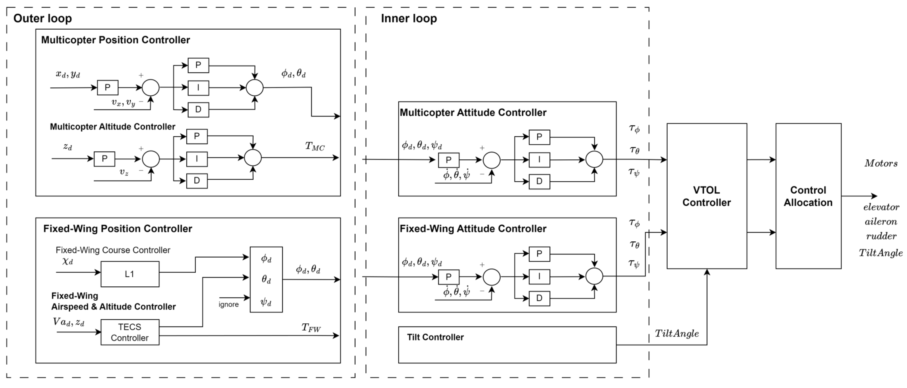
2.1. PX4 VTOL Control Architecture Overview

PX4, an open-source autopilot framework, manages VTOL aircraft using mode-dependent control modules: multicopter, transition, and fixed-wing, as visualized in Figure 1. In this architecture, PX4 activates the Total Energy Control System (TECS) only after entering fixed-wing mode, leaving the transition phase reliant on open-loop mechanisms (Section 2.2). This separation limits TECS’s ability to address dynamic coupling effects during transitions, such as the rapid aerodynamic shifts and thrust-vector changes that occur when switching between multicopter and fixed-wing modes, resulting in accumulated errors that affect post-transition stability.

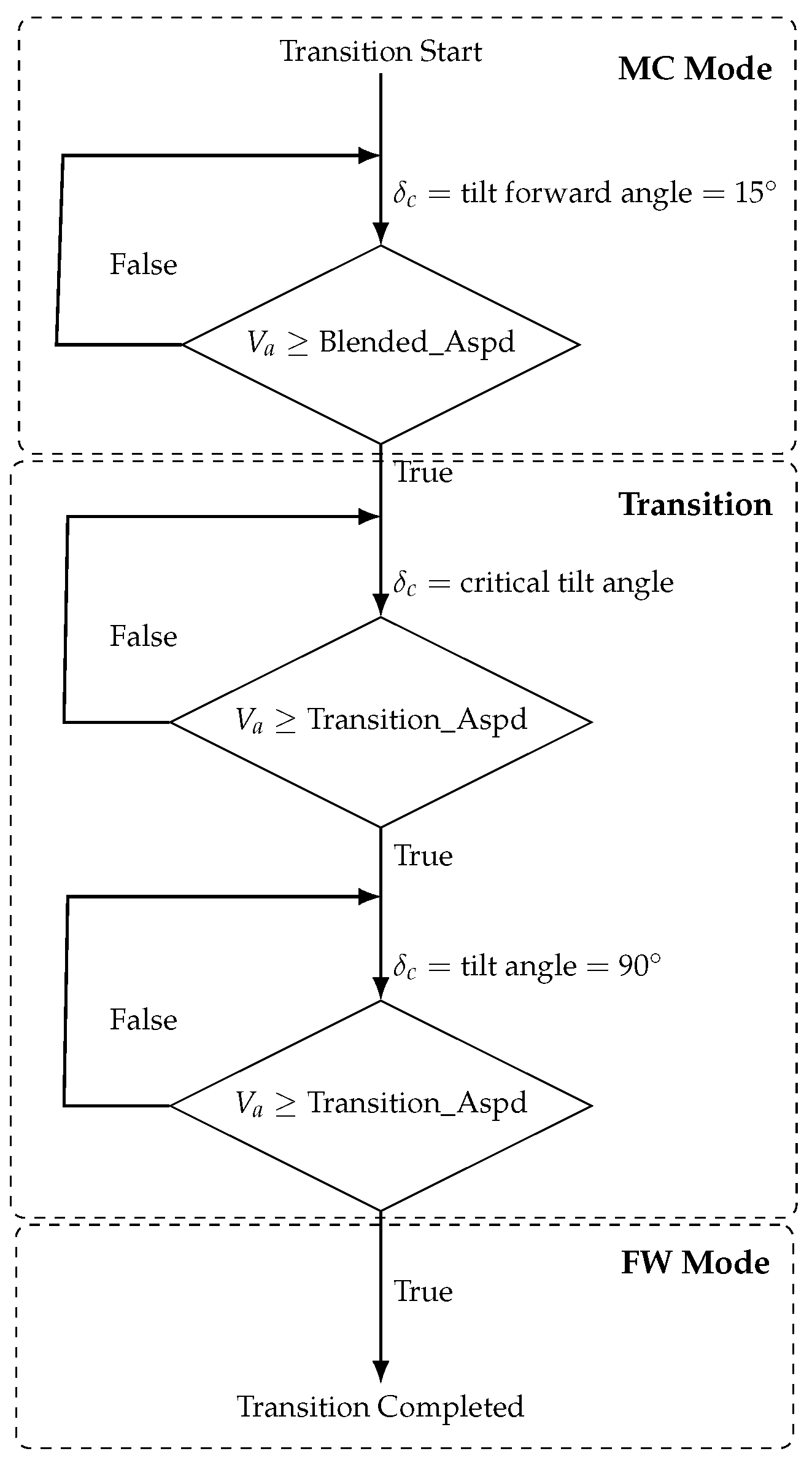
2.2. PX4 Transition Logic for Tilt-Rotor eVTOLs

PX4 transition control is primarily built upon two open-loop mechanisms:
  • Open-loop tilt-angle control: Front rotors tilt incrementally based on fixed airspeed thresholds (e.g., BLENDED_ASPD for initiating control output blending, and TRANSITION_ASPD for full fixed-wing mode engagement).
  • Linear control blending: PX4 linearly interpolates between multicopter and fixed-wing attitude controllers based on airspeed, ignoring aerodynamic nonlinearity.
This logic, as shown in Figure 2, lacks responsiveness to rapid dynamic changes, such as sudden shifts in aerodynamic forces due to rotor tilt, leading to pitch instability and altitude loss during transition [14,15].

2.3. Total Energy Control System (TECS)

TECS, introduced by Lambregts [6], regulates aircraft airspeed and altitude by manipulating throttle and pitch to control kinetic and potential energy. The total and balanced energy rates are defined as
E ˙ T = h ˙ g + v v ˙ , E ˙ B = h ˙ g v v ˙
The TECS control laws for thrust and pitch are
δ sp ( E ˙ T sp E ˙ T ) , θ sp ( E ˙ B sp E ˙ B )
As shown in Figure 3, TECS is activated only after fixed-wing engagement. This delayed activation, combined with fixed gains [9], prevents the effective mitigation of energy imbalance induced during the transition phase, particularly in tilt rotors where rotor tilt rapidly alters aerodynamic forces.

Gain Nomenclature Clarification

PX4 refers to proportional gains as “damping gains” ( D T , D B ), although they functionally behave as K p terms. This paper adopts conventional notation: K p for proportional gains and K i for integral gains.

3. Literature Review

3.1. Control Strategies for Urban Air Mobility (UAM)

Urban air mobility (UAM) has driven significant research into control systems for electric Vertical Take-Off and Landing (eVTOL) aircraft, envisioned to operate in densely populated areas [1,16]. Efficient control during critical phases, like transition and landing, is essential to ensure safety and reliability in such environments, with recent studies highlighting challenges such as maintaining stability during hover-to-forward flight transitions and achieving precise landing under varying conditions [17,18,19].

3.2. PX4-Based Transition Control and Limitations

PX4, a widely adopted open-source autopilot framework for UAV and VTOL research due to its modularity and community support, employs a rudimentary transition logic for tilt-rotor aircraft, relying on static airspeed thresholds and open-loop tilt-angle schedules that neglect nonlinear aerodynamic effects [20]. This results in pitch instability and altitude loss during transitions, particularly in tilt-rotor eVTOLs, as the system struggles to adapt to dynamic changes, leading to accumulated errors, such as deviations in pitch and altitude, that persist into fixed-wing mode, where subsequent control strategies, such as TECS, must compensate [7,21].
Similarly, ArduPilot, another widely-used open-source autopilot, implements TECS for fixed-wing mode with static gain scheduling and a state-machine-based transition logic [22]. Both systems lack dynamic adaptation during the critical transition phase, which can cause instability and altitude loss.

3.3. TECS and Energy-Based Control Advances

The Total Energy Control System (TECS), introduced by Lambregts [6], regulates altitude and airspeed in fixed-wing aircraft by managing the rate of change in specific energy states, thereby balancing throttle and pitch commands, with advances including adaptive methods [9], reinforcement learning integration [23], and model-free enhancement. However, in PX4, TECS activates only after the transition to fixed-wing mode, where its fixed gains struggle to adapt to the nonlinear dynamics and accumulated errors from the transition, often resulting in delayed post-transition stabilization [24].

3.4. Gradient-Based Adaptive Control Techniques

Gradient descent and its variants, such as nonlinear-PID adaptation using neural networks [11], adaptive TRMS stabilization [12], and Lyapunov-stable gradient dynamics [13], have gained traction as low-complexity adaptive tuning methods for real-time control, achieving stable convergence under nonlinear conditions. Recent studies have further applied steepest descent algorithms to flight control, demonstrating improved robustness and efficiency in tuning proportional–integral gains, making them suitable for integration into open-source autopilot frameworks [25,26].

3.5. Summary

Although prior studies have proposed enhancements to transition control and TECS, none have directly addressed the integration of a lightweight, gradient-based adaptive TECS controller within PX4 for tilt-rotor eVTOLs.
Recent applications of gradient-based methods in UAV control include PID autotuning for multicopters using adaptive strategies [25] and real-time optimal gain tuning leveraging flight telemetry [26]. However, these studies either focus on multicopter configurations or do not incorporate energy-based control logic like TECS. Moreover, most gradient-based approaches operate offline or require system identification, limiting their real-time adaptability in dynamically shifting aerodynamic conditions such as those found in tilt-rotor transitions.
In contrast, this study introduces SD-TECS, a steepest descent-based TECS extension fully embedded into PX4. It dynamically adjusts TECS gains during fixed-wing mode based solely on energy-rate errors, without prior model training or black-box estimators. This ensures low computational overhead and high transparency, making it suitable for real-time deployment in resource-constrained autopilot systems.
As demonstrated in Section 6.6, SD-TECS reduces the altitude integral error by 66.1% and the airspeed settling time by 57.3% compared to the standard PX4 TECS, confirming its technical advantage in energy regulation and post-transition stability.

4. Methodology

4.1. Adaptive Gain Tuning via Steepest Descent

To mitigate the limitations of static TECS gains in addressing the nonlinear dynamics of tilt-rotor eVTOLs during the post-transition phase, this study proposes a real-time gain-tuning methodology employing the steepest descent method. The proposed approach dynamically adjusts the proportional gains ( K p ) and integral gains ( K i ) of TECS based on critical flight states—such as altitude error, airspeed deviation, and pitch rate, which directly influence the pitch instability observed during transitions—thereby minimizing altitude loss and substantially enhancing stability immediately following the transition to fixed-wing mode and providing a resource-efficient solution for open-source autopilot systems. The overall control structure, inspired by Ahn and Thanh [11], is depicted in Figure 4.
The steepest descent method minimizes the error function, which is defined as
E = 1 2 ( r ( t ) y s ( t ) ) 2
where r ( t ) represents the reference state and y s ( t ) denotes the system output. The update rules for the gains are formulated as
d K p d t = η p E K p , d K i d t = η i E K i
This formulation draws inspiration from early work by Ahn and Thanh, who applied the steepest descent method to tune PID gains for a pneumatic artificial muscle (PAM) manipulator, using a single-layer structure initially described as a neural network [11]. More recent advancements, such as those by Alagoz et al., further refined this approach for nonlinear TRMS control, employing a fourth-degree polynomial to approximate system dynamics [12].
The stability of the proposed approach is substantiated by Yağmur and Alagoz, who established the Lyapunov stability of continuous-time gradient descent dynamics for η > 0 [13]. Specifically, by defining the Lyapunov function V = E , the time derivative becomes
d V d t = E K p d K p d t + E K i d K i d t = η p E K p 2 η i E K i 2 0
This guarantees the stability of the proposed method for positive learning rates.

4.1.1. Motivation for the Steepest Descent Method

During the transition from multicopter to fixed-wing mode, the aircraft undergoes significant aerodynamic shifts and thrust-vector changes, resulting in residual effects that persist into the post-transition phase. Fixed-gain TECS, activated only after the transition to fixed-wing mode, is insufficient to address these dynamic variations, often leading to suboptimal altitude control and delayed stabilization. The steepest descent method facilitates real-time adaptation by iteratively optimizing the gains based on current error metrics (e.g., altitude and energy-rate deviations), providing an effective and resource-efficient solution for open-source platforms such as PX4. By directly minimizing the error function, this method ensures rapid adaptation to the dynamic flight conditions immediately following the transition, thereby substantially enhancing post-transition stability.

4.1.2. Steepest Descent Gain-Update Formulation

In the TECS framework, two separate control loops are used to manage the total energy rate E ˙ T and balanced energy rate E ˙ B , corresponding to throttle and pitch control, respectively. Each loop uses independent proportional and integral gains— ( K p S T E , K i S T E ) for total energy and ( K p S B E , K i S B E ) for balanced energy. Although the derivation below is presented using a general energy rate E ˙ for brevity, the same steepest descent logic is applied independently to both E ˙ T and E ˙ B , resulting in separate gain updates for each loop.
The steepest descent method optimizes the gains by minimizing a cost function that quantifies the error between the desired and actual energy rates. The cost function is defined as
J ( k ) = 1 2 ( E ˙ sp ( k ) E ˙ ( k ) ) 2
where E ˙ sp ( k ) represents the desired energy rate and  E ˙ ( k ) denotes the actual energy rate. The control structure, inspired by Ahn and Thanh [11], consists of a control optimizer that adjusts the gains and an adaptation optimizer that estimates the system dynamics, as depicted in Figure 4.
To minimize the cost function, the steepest descent method updates the proportional gains ( K p ) and integral gains ( K i ) using the gradients of J ( k ) with respect to the gains. Applying the chain rule, the partial derivatives are expressed as
J ( k ) K p = J ( k ) E ˙ ( k ) · E ˙ ( k ) u ( k ) · u ( k ) x ( k ) · x ( k ) K p J ( k ) K i = J ( k ) E ˙ ( k ) · E ˙ ( k ) u ( k ) · u ( k ) x ( k ) · x ( k ) K i
Defining the energy-rate error as e ( k ) = E ˙ sp ( k ) E ˙ ( k ) , the components of the chain rule are derived as
J ( k ) E ˙ ( k ) = e ( k ) E ˙ ( k ) u ( k ) = f ( x ( k ) ) x ( k ) K p = e p ( k ) , x ( k ) K i = e i ( k )
Here, f ( x ( k ) ) is the sigmoid function used to shape the gain adjustments, providing a smooth and bounded response to error variations, defined as
f ( x ) = 2 ( 1 e x Y g ) Y g ( 1 + e x Y g )
with its derivative
f ( x ) = 4 e x Y g ( 1 + e x Y g ) 2
The input x ( k ) to the sigmoid function is computed based on the proportional and integral error terms:
x ( k ) = K p ( k ) e p ( k ) + K i ( k ) e i ( k ) , e p ( k ) = E ˙ sp ( k ) E ˙ ( k ) , e i ( k ) = e p ( k ) d t
where e p ( k ) is the proportional error, e i ( k ) is the integral error, and  Y g is a tuning parameter that shapes the sigmoid curve, as shown in Figure 5.
Substituting the components from Equation (8) into Equation (7), the gradients become
J ( k ) K p = e ( k ) · f ( x ( k ) ) · e p ( k ) J ( k ) K i = e ( k ) · f ( x ( k ) ) · e i ( k )
These gradients are then used in the steepest descent update rule to adjust the gains.
Finally, the gain update rules for the two control loops are applied as
K p S T E ( k + 1 ) = K p S T E ( k ) η S T E · J T ( k ) K p K i S T E ( k + 1 ) = K i S T E ( k ) η S T E · J T ( k ) K i K p S B E ( k + 1 ) = K p S B E ( k ) η S B E · J B ( k ) K p K i S B E ( k + 1 ) = K i S B E ( k ) η S B E · J B ( k ) K i
The learning rates η S T E and η S B E correspond to the steepest descent adaptation gains for the total energy control loop ( E ˙ T ) and the balanced energy control loop ( E ˙ B ), respectively. These learning rates determine the responsiveness of the gain updates and, as established by Yağmur and Alagoz [13], guarantee Lyapunov stability for all η > 0 . In this implementation, identical learning rates are used for both the proportional and integral terms in each loop— η S T E for total energy control and η S B E for balanced energy control—for simplicity and computational efficiency. While separate learning rates for K p and K i are possible and often recommended for fine-tuned control, the unified approach has demonstrated sufficient performance in our simulation-based evaluation.

4.2. Implementation and Validation
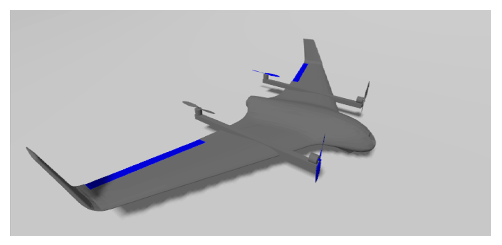
The proposed method was implemented and tested using PX4 simulations, focusing on the post-transition phase in fixed-wing mode. Performance was evaluated by comparing altitude stability and recovery time against the default fixed-gain TECS.

5. Simulation Model

5.1. Aircraft Configuration and Longitudinal Dynamics

The simulation framework is designed to model and analyze the longitudinal dynamics of a tilt-rotor eVTOL platform, with a focus on altitude, airspeed, and pitch attitude. The aircraft model reflects a conventional tilt-rotor configuration with transition-capable rotors, which adjust their tilt angle to switch between hover and forward flight modes, as described in the PX4 transition logic (Section 2.2) and fixed-wing surfaces. This study focuses on a small unmanned tilt-rotor eVTOL, with a total mass of 5.22 kg and a wing surface area of 0.75 m2, transitioning at speeds starting from 6 m/s and operating in fixed-wing mode at speeds starting from 15 m/s (with a maximum speed capability of 25 m/s for the aircraft), as defined by the transition parameters (BLENDED_ASPD and TRANSITION_ASPD). The physical and aerodynamic parameters used in this study are based on a representative subscale tilt-rotor configuration implemented in the Gazebo simulation environment (Figure 6). These values form the basis for computing the aerodynamic forces and moments throughout the simulation.
For the symbols shown in Table 1, m is the total mass; J x , J y , J z , J x z are the moments and products of inertia; S wing is the wing surface area; b is wingspan; and  c ¯ is the mean aerodynamic chord.
The aerodynamic coefficients in Table 2 are used to calculate the lift ( C L ), drag ( C D ), and moment ( C m ) coefficients dynamically as functions of the angle of attack ( α ), pitch rate (q), and elevator deflection ( δ e ) according to the following equations:
C L = C L 0 + C L α α + C L q q c ¯ 2 v + C L δ e δ e
C D = C D 0 + C D α α + C D α 2 α 2 + C D q q c ¯ 2 v + C D δ e δ e
C m = C m 0 + C m α α + C m q q c ¯ 2 v + C m δ e δ e
These equations dynamically compute the aerodynamic coefficients based on the instantaneous angle of attack α , pitch rate q, and elevator deflection δ e .
Table 1. Physical properties.
SymbolValueDescription
m5.22 kgTotal mass of the aircraft
J x 1.229 kg·m2Moment of inertia about the x-axis
J y 0.1702 kg·m2Moment of inertia about the y-axis
J z 0.8808 kg·m2Moment of inertia about the z-axis
J x z 0.9343 kg·m2Product of inertia
S wing 0.75 m2Wing surface area
b2.10 mWingspan
c ¯ 0.3571 mMean aerodynamic chord
Table 2. Aerodynamic coefficients of the aircraft model.
SymbolValueDescription
C L 0 0.0867Lift coefficient at zero angle of attack
C L α 4.02Lift coefficient per radian of angle of attack
C L q 3.8954Lift coefficient per unit pitch rate
C L δ e 0.278Lift coefficient per unit elevator deflection
C D 0 0.0197Drag coefficient at zero angle of attack
C D α 0.0791Drag coefficient per radian of angle of attack
C D α 2 1.06Drag coefficient per radian squared of angle of attack
C D q 0.0Drag coefficient per unit pitch rate
C D δ e 0.0633Drag coefficient per unit elevator deflection
C m 0 0.0302Moment coefficient at zero angle of attack
C m α −0.126Moment coefficient per radian of angle of attack
C m q −1.3047Moment coefficient per unit pitch rate
C m δ e −0.206Moment coefficient per unit elevator deflection
The corresponding aerodynamic forces and moments are
L = 1 2 ρ v 2 S C L , D = 1 2 ρ v 2 S C D , M = 1 2 ρ v 2 S C m
where L is the lift force, D is the drag force, M is the pitching moment, ρ is the air density, v is the airspeed, and S is the wing area.

5.2. Control Architecture

The control architecture of the tilt-rotor eVTOL is mode-dependent and composed of cascaded feedback loops tailored to the vehicle’s flight configuration. During vertical flight (multicopter mode), PID-based controllers regulate the body angular rates and altitude, whereas during forward flight (fixed-wing mode), the control switches to a fixed-wing attitude controller complemented by a Total Energy Control System (TECS), which manages the coupled airspeed and altitude dynamics. Each flight mode employs a distinct control strategy, summarized as follows:
  • Multicopter Flight Mode:
    Attitude Stabilization: A cascaded PID controller regulates the roll, pitch, and yaw rates using angular rate feedback.
    Altitude Hold: A proportional–integral (PI) controller tracks the desired altitude by modulating the vertical thrust.
  • Fixed-Wing Flight Mode:
    Attitude Control: A pitch attitude controller maintains longitudinal stability using elevator surface deflection.
    Energy Management: TECS regulates the total and balanced energy rates by coordinating the throttle and pitch commands.
This architecture enables mode-specific control tuning and ensures a seamless handover between the multicopter and fixed-wing control laws during the transition phase.

6. Simulation Results

6.1. Simulation Setup

Simulations were conducted in MATLAB Simulink with TECS running at 100 Hz, matching PX4’s control frequency. The proposed adaptive gain-tuning algorithm was integrated directly into the TECS loop to ensure real-time compatibility. Three configurations were tested: (1) the default PX4 TECS, (2) a manually tuned TECS, and (3) the proposed SD-TECS. The focus was on the post-transition phase, starting from a state with an altitude of 10 m and an airspeed of 0.1 m/s, reflecting the conditions immediately after transition. To assess robustness to environmental disturbances, we first evaluated performance under calm conditions (no wind) as a baseline. Subsequently, we applied a linear wind model, with wind speeds ranging from 0 m/s to 5 m/s, reflecting steady-wind conditions typical for longitudinal dynamics analysis in urban air mobility scenarios. Given that this study focuses on longitudinal dynamics, wind directions were set to 0 degrees (headwind from the north) and 180 degrees (tailwind from the south) to evaluate their impact on longitudinal stability, applied in the body frame. The simulations targeted fixed-wing mode operation at speeds starting from 15 m/s (with a maximum speed capability of 25 m/s for the aircraft), as defined by the transition parameters (BLENDED_ASPD and TRANSITION_ASPD), starting from a transition speed of 6 m/s, and were conducted using a small unmanned eVTOL (mass: 5.22 kg; wing area: 0.75 m2). The simulations used two parameter groups: VTOL transition parameters and TECS gain-tuning parameters, as summarized in Table 3. These define the mode-switching behavior and control characteristics for tilt-rotor eVTOLs.
All simulations were performed on a system with the following specifications: an AMD Ryzen 7 5700G CPU, 32 GB of RAM, and MATLAB 2024b (with Simulink) running on Windows 11. GPU acceleration was not utilized in these simulations.

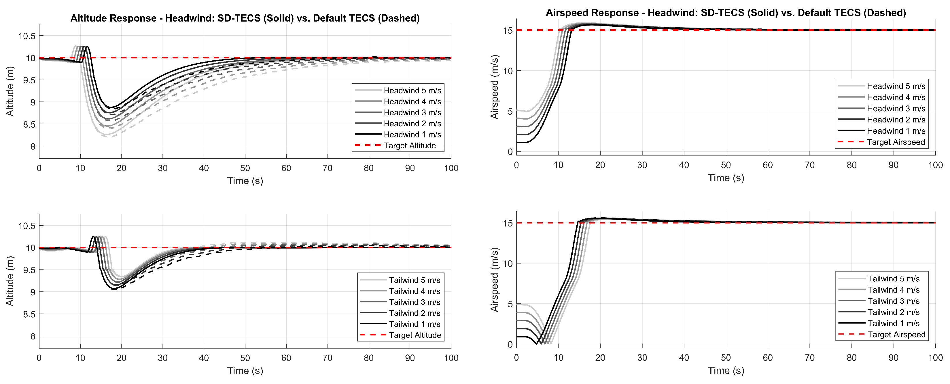
6.2. TECS State Response

Figure 7 compares the altitude and airspeed responses over the simulation period (0–100 s) for three TECS variants: SD-TECS, PX4 TECS with tuned gains, and PX4 TECS with default gains. To aid interpretation, the background of each plot illustrates the aircraft’s flight mode: the gray region corresponds to multicopter mode, the yellow region denotes the transition phase, and the light-blue region represents fixed-wing mode, during which TECS actively operates. The vertical dashed line at 13.8 s marks the exact transition completion point, and the dashed black box highlights the time window analyzed in the zoomed-in plots (Figure 8 and Figure 9), revealing that SD-TECS demonstrated faster altitude recovery, effectively reduced altitude loss in the post-transition phase, and also achieved faster airspeed stabilization compared to the default and tuned TECS variants. This demonstrates that the steepest descent approach effectively enhances both altitude and airspeed control during the fixed-wing phase, owing to its adaptive gain tuning that mitigates the nonlinear dynamics impacting both metrics post-transition.
For a detailed view of recovery behavior, Figure 8 and Figure 9 provide zoomed-in plots of the post-transition phase (starting at 13.8 s), revealing that SD-TECS achieved more rapid altitude recovery and airspeed stabilization compared to the other TECS configurations.  

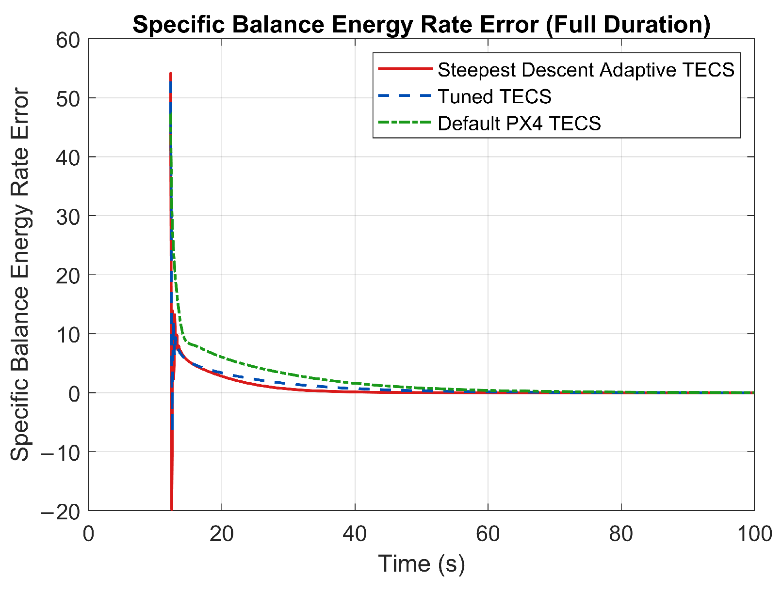
6.3. Energy-Rate Error Response

Figure 10 and Figure 11 illustrate the responses of the specific total energy rate (STE) and the specific balanced energy rate (SBE) errors post-transition. SD-TECS achieved a significantly faster reduction in both energy errors than the PX4 TECS with default and tuned gains, leading to quicker stabilization of the altitude and airspeed. The rapid reduction in the energy-rate errors highlights SD-TECS’s superior ability to adapt to the nonlinear dynamics of the transition phase, ensuring smoother and more stable flight performance by effectively compensating for the limitations of other TECS variants in managing energy errors during the post-transition phase.

6.4. TECS Control Outputs

Figure 12 and Figure 13 illustrate the thrust and pitch outputs for the different TECS variants. SD-TECS dynamically adjusted these control outputs more effectively than the other methods, contributing significantly to the enhanced stability during the post-transition phase, as its ability to adaptively modify thrust and pitch ensured smoother flight control, thereby minimizing oscillations and improving overall aircraft response, particularly during the post-transition phase with nonlinear dynamics, where other methods may struggle to stabilize the aircraft quickly.

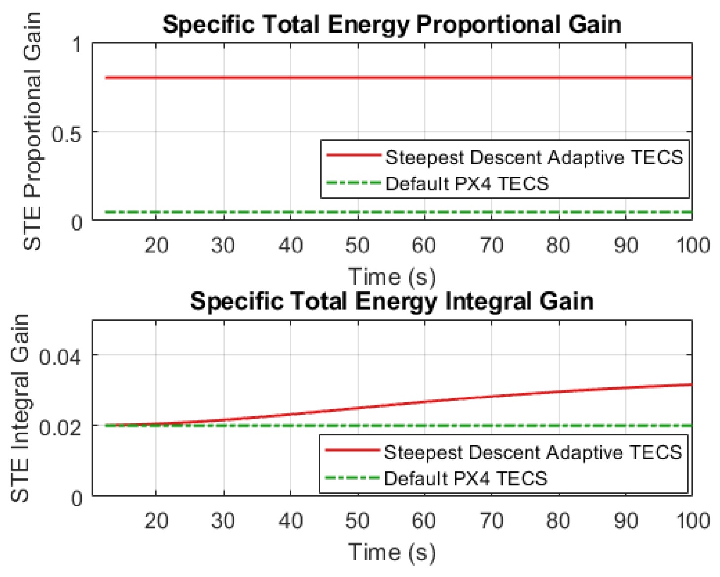
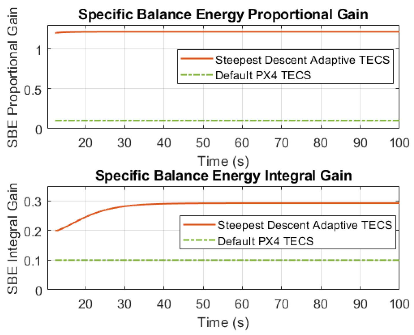
6.5. TECS Gain Tuning

Figure 14 and Figure 15 show the real-time adjustment of the proportional and integral gains for the STE and SBE loops in SD-TECS, enabled by the steepest descent method. This dynamic gain tuning allowed SD-TECS to quickly adapt to changes in the altitude and energy errors, ensuring stability and smooth performance during the post-transition phase, in contrast with the tuned TECS, which relied on fixed, pre-calibrated gains that did not adjust in real time. While the proportional gains remained stable in both methods, SD-TECS dynamically adjusted the integral gains, enabling faster stabilization of the altitude and airspeed, thus enhancing its ability to handle the nonlinear dynamics of the post-transition phase, whereas the tuned TECS lacked flexibility and relied on static values.

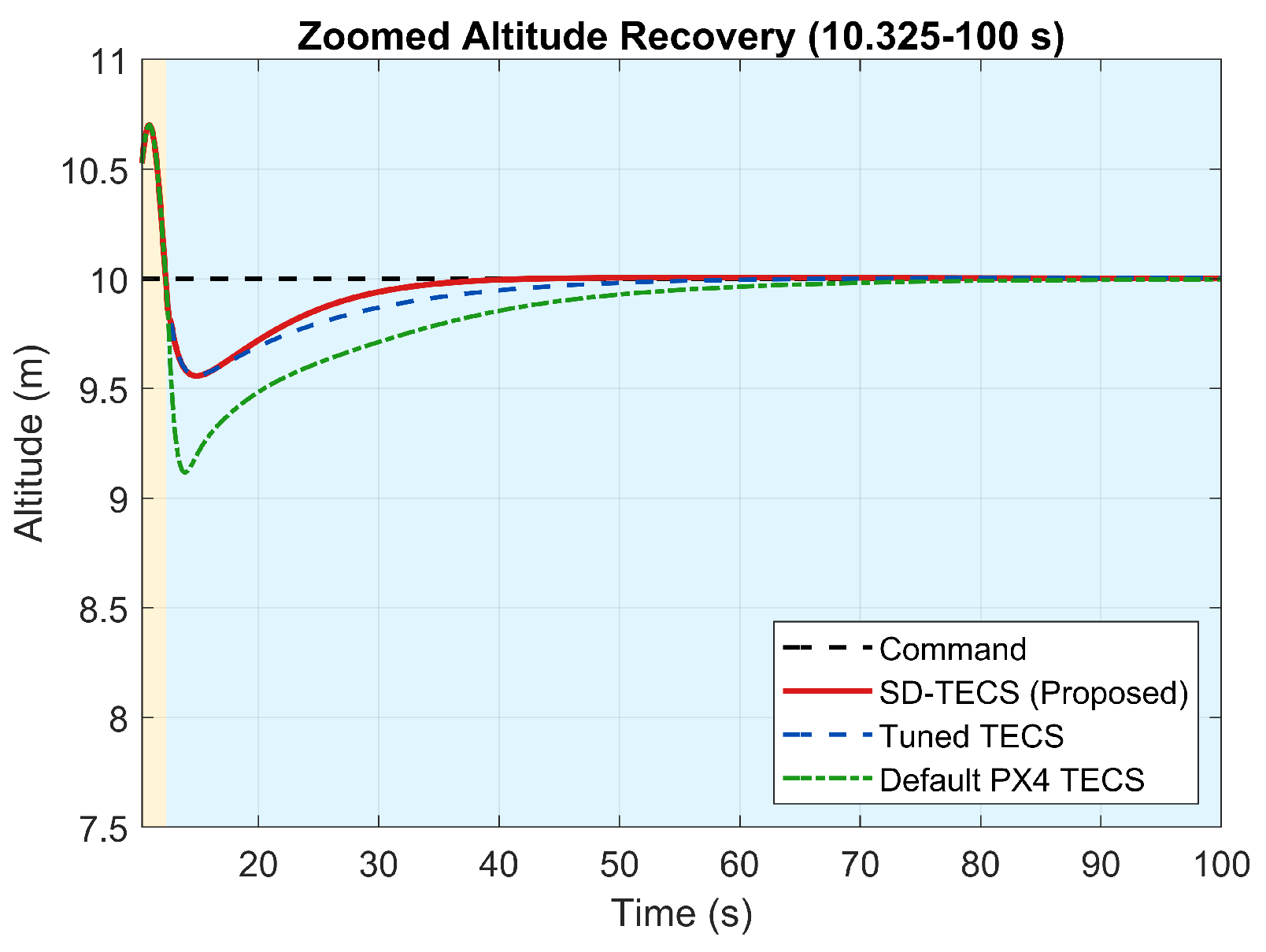
6.6. Performance Analysis

6.6.1. Transient Response Metrics

Performance was evaluated using key metrics: settling time, maximum altitude loss, and integration of errors for both altitude and airspeed. Table 4 presents the comparison results between the three TECS variants—PX4 default, tuned TECS, and the proposed SD-TECS—based on a 3% tolerance range around the target altitude (10 m) and airspeed (15 m/s). SD-TECS demonstrated the fastest response, reducing the altitude settling time to 28.56 s, a 35.5% improvement over the PX4 default (44.31 s) and 20.3% over the tuned TECS (35.31 s). The airspeed settled at 23.14 s for SD-TECS, outperforming the PX4 default (40.20 s) by 48.9% and the tuned TECS (26.75 s) by 13.5%. In terms of overshoot, SD-TECS minimized the maximum altitude loss to 0.83 m, representing a 42.4% improvement over the PX4 default and a 4.8% improvement over the tuned TECS. The airspeed overshoot was also the lowest at 0.61 m/s, showing a 48.9% reduction compared to the PX4 default (1.16 m/s). Additionally, SD-TECS achieved the smallest integration of errors: 12.78 m2 for altitude and 148.02 m·s for airspeed, representing 66.1% and 12.0% improvements over the PX4 default, respectively. Overall, SD-TECS consistently outperformed both baseline methods, demonstrating superior control accuracy, energy efficiency, and adaptability in dynamic post-transition flight scenarios.

6.6.2. Quantitative Evaluation: MAE, IAE, and ITAE

We utilized three commonly accepted quantitative metrics to assess control accuracy and efficiency [27].
These metrics are defined as follows:
  • MAE (Mean Absolute Error): 1 T 0 T | e ( t ) | d t ;
  • IAE (Integral of Absolute Error): 0 T | e ( t ) | d t ;
  • ITAE (Integral of Time-weighted Absolute Error): 0 T t · | e ( t ) | d t .
Here, e ( t ) represents the tracking error at time t.
As shown in Figure 16, the SD-TECS consistently yielded the lowest errors across all metrics for both altitude and airspeed control. Notably, it reduced the altitude IAE and ITAE by more than 65% and 75%, respectively, compared to the PX4 default controller.

6.7. Robustness Analysis

Section 6.6 demonstrated SD-TECS’s superior performance under baseline conditions, where it achieved faster convergence and reduced errors compared to the PX4 default. To further evaluate its applicability in real-world scenarios, this section examines the robustness of SD-TECS to environmental wind disturbances. A linear wind model was chosen to focus on longitudinal dynamics, which act as the primary disturbance in the post-transition phase for tilt-rotor eVTOLs, particularly in urban air mobility contexts where stable flight under varying wind conditions is essential. Specifically, we introduced wind speeds ranging from 0 m/s to 5 m/s, considering headwind (0 degrees) and tailwind (180 degrees) directions in the body frame. Figure 17 illustrates the altitude and airspeed responses under headwind and tailwind conditions for both SD-TECS and the PX4 default. The target altitude (10 m) and airspeed (15 m/s) are indicated with red dashed lines to highlight the desired setpoints. The line intensity in the figures reflects the wind speed, with 0 m/s represented by the darkest shade (black) and 5 m/s by the lightest shade (gray), providing a clear visual distinction of wind speed effects. As illustrated, SD-TECS demonstrated superior stability and control precision compared to the PX4 default across all tested wind conditions, achieving faster convergence to the target values with reduced oscillations. This enhanced performance is attributed to SD-TECS’s adaptive gain tuning, which enables more responsive and precise control compared to the fixed-gain approach of the PX4 default, as discussed further in Section 7.

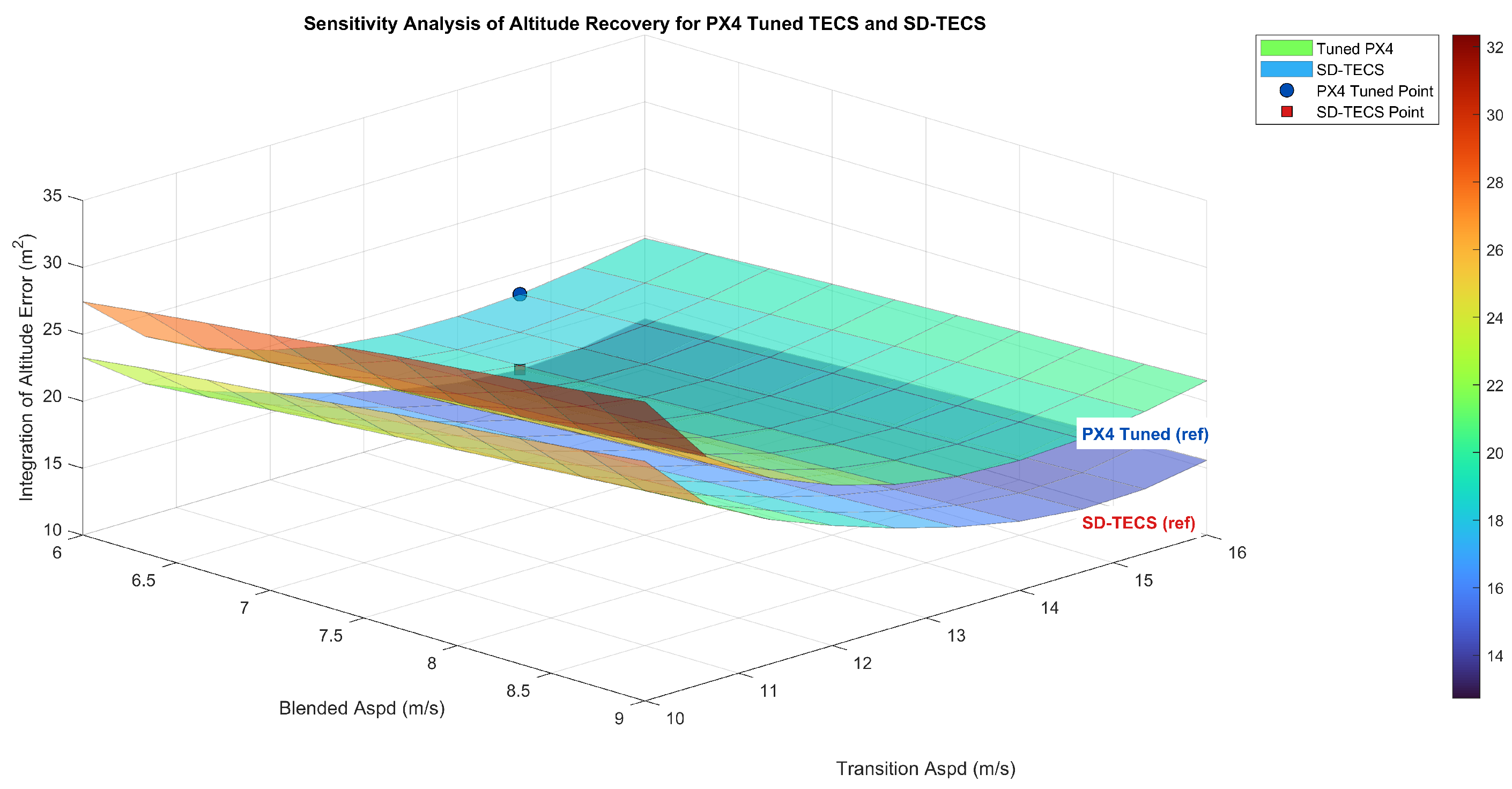
6.8. Sensitivity Analysis

Figure 18 evaluates the adaptability of SD-TECS to various flight conditions by analyzing its performance under different transition parameter settings. Specifically, BLENDED_ASPD and TRANSITION_ASPD were varied in the ranges of 6–9 m/s and 10–16 m/s, respectively, while keeping other PX4 parameters constant. The tilt rate was also tested, but its influence on transition behavior was found to be negligible, so it was excluded to focus on the two most influential parameters affecting fixed-wing engagement and energy-control dynamics. The surface plot compares the integration of altitude error for both the tuned TECS and the proposed SD-TECS across all parameter combinations, with the experimental reference point used in the performance analysis (i.e., BLENDED_ASPD = 6, TRANSITION_ASPD = 15) marked explicitly on the surface, highlighting that SD-TECS achieved superior performance under this condition and maintained a consistently lower altitude error across the tested parameter ranges, demonstrating that it is not only effective under nominal conditions but also adaptable to parameter variations, thereby making it a reliable option for real-world VTOL operations.

6.9. Computational Complexity Analysis

This study evaluated the computational complexity of SD-TECS compared to the baseline TECS using both theoretical and empirical approaches. Theoretically, both SD-TECS and TECS exhibit a time complexity of O ( n ) (where n is the number of time steps) and a space complexity of O ( n ) with data logging, or  O ( 1 ) otherwise, due to fixed computations per time step. SD-TECS incorporates adaptive gain adjustment via a steepest descent method, introducing additional computations (e.g., exponential and multiplication operations) but maintaining O ( 1 ) complexity per time step by avoiding iterative loops.
To quantify the computational overhead empirically, the Simulink Profiler measured the execution times of the TECS block within the SD-TECS and TECS subsystems. The results, based on 100 measurements, are summarized in Table 5. The TECS block was called 103,356 times during the 100 s simulation, operating at 100 Hz within a model simulated using a FixedStepAuto solver at 400 Hz.
SD-TECS recorded an average total execution time of 0.7188 s (standard deviation: 0.0062 s), compared to 0.6500 s (standard deviation: 0.0082 s) for TECS, resulting in a 10.58% increase in simulation time. On a per-call basis, SD-TECS required approximately 6.953 μs per call, while TECS required 6.289 μs, indicating a modest additional computational load due to the steepest descent method block. These results demonstrate that SD-TECS maintains computational efficiency suitable for real-time implementation on typical eVTOL hardware (e.g., Pixhawk), with the modest overhead well within acceptable limits for urban air mobility applications.

7. Discussion and Conclusions

This paper proposed SD-TECS to enhance the post-transition stability and recovery of hybrid UAVs. The simulation results showed that SD-TECS outperformed both the default and manually tuned PX4 TECS in key performance metrics, such as settling time, altitude recovery, and error reduction, under various wind conditions and initial conditions (Section 6.6 and Section 6.7). The key advantage of SD-TECS lies in its adaptive gain tuning, particularly the dynamic adjustment of the integral gains, which improves the response to real-time energy and altitude errors. This approach allows for more effective control during the post-transition phase without modifying PX4’s existing transition logic, ensuring seamless integration with the autopilot system.
The robustness analysis (Section 6.7) further demonstrated SD-TECS’s superior performance across wind disturbances from calm (0 m/s) to 5 m/s steady winds, where it maintained consistent stability and control accuracy throughout the tested scenarios.
The sensitivity analysis (Section 6.8) confirmed the adaptability of SD-TECS under various transition parameter settings, indicating its consistency across varying transition conditions. However, this study was limited to small unmanned eVTOLs and low- to medium-speed ranges starting from 15 m/s in fixed-wing mode. Additionally, the use of a linear wind model simplified the analysis but did not fully capture the complexity of real-world wind disturbances, such as significant turbulence or wind shear, which may affect performance in actual urban air mobility environments.
Future work will focus on extending the framework to include 6-DOF flight models to evaluate robustness against multi-directional disturbances. This will involve conducting real-world flight tests to validate performance in operational environments using a physical tilt-rotor eVTOL platform, including experimental TECS state-response plots for altitude and airspeed; assessing performance in higher speed ranges (e.g., above 15 m/s); and incorporating more realistic wind models, such as turbulence and wind shear, to evaluate SD-TECS’s performance under complex environmental conditions. In conclusion, SD-TECS provides a practical, resource-efficient solution for enhancing the performance of hybrid unmanned VTOL platforms, offering a promising approach to improve post-transition flight stability and facilitate broader adoption in urban air mobility applications.

Author Contributions

Methodology, N.P.N.; Software, C.L.; Validation, C.L.; Investigation, C.L.; Writing—original draft, C.L.; Writing—review & editing, S.B.; Supervision, S.K.H.; Funding acquisition, S.K.H. All authors have read and agreed to the published version of the manuscript.

Funding

This work was supported by the Future Space Navigation and Satellite Research Center through the National Research Foundation, funded by the Ministry of Science and ICT, the Republic of Korea (2022M1A3C2074404); by the Basic Science Research Program through the National Research Foundation of Korea (NRF), funded by the Ministry of Education (2020R1A6A1A03038540); and by the IITP (Institute of Information and Communications Technology Planning and Evaluation) under the ITRC (Information Technology Research Center) grant, funded by the Korean government (Ministry of Science and ICT) (IITP-2025-RS-2024-00437494).

Data Availability Statement

The original contributions presented in this study are included in the article. Further inquiries can be directed to the corresponding author.

Conflicts of Interest

The authors declare no conflicts of interest.

Abbreviations

The following abbreviations are used in this manuscript:
SD-TECSSteepest Descent-based Total Energy Control System
TECSTotal Energy Control System
PX4PX4 Autopilot
eVTOLElectric Vertical Take-Off and Landing
UAMUrban Air Mobility
IAEIntegral of Absolute Error
ITAEIntegral of Time-weighted Absolute Error
MAEMean Absolute Error

References

  1. Straubinger, A.; Rothfeld, R.; Shamiyeh, M.; Büchter, K.-D.; Kaiser, J.; Plötner, K.O. An overview of current research and developments in urban air mobility. Annu. Rev. Control. Robot. Auton. Syst. 2020, 3, 417–441. [Google Scholar] [CrossRef]
  2. Saleem, O.; Kazim, M.; Iqbal, J. Robust position control of VTOL UAVs using a linear quadratic rate-varying integral tracker: Design and validation. Drones 2025, 9, 73. [Google Scholar] [CrossRef]
  3. Tutsoy, O.; Asadi, D.; Ahmadi, K.; Nabavi-Chashmi, S.Y.; Iqbal, J. Minimum distance and minimum time optimal path planning with bioinspired machine learning algorithms for faulty unmanned air vehicles. IEEE Trans. Intell. Transp. Syst. 2024, 25, 9069–9077. [Google Scholar] [CrossRef]
  4. PX4 Autopilot. PX4 Open-Source Autopilot. Available online: https://px4.io/ (accessed on 3 June 2025).
  5. Meier, L.; Honegger, D.; Pollefeys, M. A Survey of Open-Source UAV Autopilots. Electronics 2024, 13, 4785. [Google Scholar] [CrossRef]
  6. Lambregts, A.A. Integrated System Design for Flight and Propulsion Control Using Total Energy Principles. In Proceedings of the AIAA Aircraft Design, Systems and Technology Meeting, Fort Worth, TX, USA, 17–19 October 1983. AIAA-83-2561. [Google Scholar] [CrossRef]
  7. PX4 Discussion Forum. Pitch up on Transitions to Fixed Wing. 2019. Available online: https://discuss.px4.io/t/pitch-up-on-transitions-to-fixed-wing/11287 (accessed on 3 June 2025).
  8. Brigido, D.; Rodriguez, H. Experimental Validation of an Adaptive Total Energy Control System Strategy for the Longitudinal Dynamics of a Fixed-Wing Aircraft. J. Aerosp. Eng. 2015, 28, 04014103. [Google Scholar] [CrossRef]
  9. Anandakumar, A.; Bernstein, D.S.; Goel, A. Adaptive Energy Control of Longitudinal Aircraft Dynamics. In Proceedings of the AIAA Scitech 2022 Forum, San Diego, CA, USA, 3–7 January 2022. [Google Scholar] [CrossRef]
  10. He, A.; Zhang, Y.; Zhao, H.; Wang, B.; Gao, Z. Adaptive Fault-Tolerant Control of a Hybrid VTOL UAV against Actuator Faults and Model Uncertainties under Fixed-Wing Mode. Int. J. Aerosp. Eng. 2022, 2022, 8191154. [Google Scholar] [CrossRef]
  11. Ahn, K.K.; Thanh, T.D.C. Nonlinear PID control to improve the control performance of the pneumatic artificial muscle manipulator using neural network. J. Mech. Sci. Technol. 2005, 19, 106–115. [Google Scholar] [CrossRef]
  12. Alagoz, B.B.; Tepljakov, A.; Kavuran, G.; Alisoy, H. Adaptive control of nonlinear TRMS model by using gradient descent optimizers. In Proceedings of the 2018 International Conference on Artificial Intelligence and Data Processing (IDAP), Malatya, Turkey, 28–30 September 2018; IEEE: Piscataway, NJ, USA, 2018. [Google Scholar]
  13. Yağmur, N.; Alagoz, B.B. Comparison of solutions of numerical gradient descent method and continuous time gradient descent dynamics and Lyapunov stability. Turk. J. Electr. Eng. Comput. Sci. 2017, 25, 3897–3908. [Google Scholar]
  14. Lu, K.; Tian, H.; Zhen, P.; Lu, S.; Chen, R. Conversion Flight Control for Tiltrotor Aircraft via Active Disturbance Rejection Control. Aerospace 2022, 9, 155. [Google Scholar] [CrossRef]
  15. Chen, Q.; Hu, Z.; Geng, J.; Bai, D.; Mousaei, M.; Scherer, S. A Unified MPC Strategy for a Tilt-rotor VTOL UAV Towards Seamless Mode Transitioning. arXiv 2024, arXiv:2402.07375. Available online: https://arxiv.org/abs/2402.07375 (accessed on 3 June 2025).
  16. Garrow, L.A.; German, B.J.; Leonard, C.E. Urban air mobility: A comprehensive review and comparative analysis with autonomous and electric ground transportation for informing future research. Transp. Res. Part Emerg. Technol. 2021, 132, 103377. Available online: https://www.sciencedirect.com/science/article/pii/S0968090X21003788 (accessed on 3 June 2025). [CrossRef]
  17. Sengupta, R.; Bulusu, V.; Mballo, C.E.; Onat, E.B.; Cao, S.A. Urban Air Mobility Research Challenges and Opportunities. Annu. Rev. Control. Robot. Auton. Syst. 2025, 8, 407–431. [Google Scholar] [CrossRef]
  18. Schoser, J.J.; Cuadrat-Grzybowski, M.; Castro, S.G.P. Preliminary control and stability analysis of a long-range eVTOL aircraft. In Proceedings of the AIAA SciTech 2022 Forum, San Diego, CA, USA, 3–7 January 2022. [Google Scholar] [CrossRef]
  19. Sobiesiak, L.; Topping, H.F. Modelling and control of transition flight of an eVTOL tandem tilt-wing aircraft. In Proceedings of the 8th European Conference for Aeronautics and Space Sciences (EUCASS), Madrid, Spain, 1–4 July 2019; Available online: https://www.eucass.eu/doi/EUCASS2019-0137.pdf (accessed on 3 June 2025).
  20. Salem, W.A.; Mohamady, O.; Draz, M.; El-bayoumi, G. Promoting the Maneuverability and Fault-Tolerant Control of Hybrid VTOL UAVs; Springer: Berlin/Heidelberg, Germany, 2023; Available online: https://link.springer.com/article/10.1007/s13369-023-08255-0 (accessed on 3 June 2025).
  21. Fixed-wing Altitude/Position Controller Tuning|PX4 Guide. PX4 Official Documentation. Available online: https://docs.px4.io/main/en/config_fw/position_tuning_guide_fixedwing.html (accessed on 3 June 2025).
  22. ArduPilot. QuadPlane Transition Control. Retrieved May 2025. Available online: https://ardupilot.org/plane/docs/quadplane-transitions.html (accessed on 3 June 2025).
  23. Choi, J.; Kim, H.M.; Hwang, H.J.; Kim, Y.-D.; Kim, C.O. Modular Reinforcement Learning for Autonomous UAV Flight Control. Drones 2023, 7, 418. [Google Scholar] [CrossRef]
  24. Jimenez, P.; Lichota, P.; Agudelo, D.; Rogowski, K. Experimental Validation of Total Energy Control System for UAVs. Energies 2020, 13, 14. [Google Scholar] [CrossRef]
  25. Spencer, J.; Lee, J.; Paredes, J.A.; Goel, A.; Bernstein, D.S. An Adaptive PID Autotuner for Multicopters with Experimental Results. University of Michigan, 2021. Available online: https://dsbaero.engin.umich.edu/wp-content/uploads/sites/441/2022/10/An_Adaptive_PID_Autotuner_for_Multicopters_with_Experimental_Results.pdf (accessed on 3 June 2025).
  26. Abdelkader, M.; Mabrok, M.; Koubaa, A. OCTUNE: Optimal Control Tuning Using Real-Time Data with Algorithm and Experimental Results. Sensors 2022, 22, 9240. [Google Scholar] [CrossRef] [PubMed]
  27. Zhang, Y.; Liu, X.; Zhang, B. Iterative learning control for path-following of ASV with the ice floes auto-select avoidance mechanism. IEEE Trans. Intell. Transp. Syst. 2025. [Google Scholar] [CrossRef]
Figure 1. PX4 VTOL control structure.
Drones 09 00414 g001
Figure 2. Flowchart for the transition process in flight modes.
Drones 09 00414 g002
Figure 3. PX4 TECS control structure.
Drones 09 00414 g003
Figure 4. Block diagram of gradient descent optimizer control in TECS.
Drones 09 00414 g004
Figure 5. Sigmoid function shapes for different Y g values.
Drones 09 00414 g005
Figure 6. Tilt-rotor Gazebo model.
Drones 09 00414 g006
Figure 7. TECS state response: altitude and airspeed comparison (0–100 s).
Drones 09 00414 g007
Figure 8. Zoomed-in view of altitude response.
Drones 09 00414 g008
Figure 9. Zoomed-in view of airspeed response.
Drones 09 00414 g009
Figure 10. Specific total energy-rate error.
Drones 09 00414 g010
Figure 11. Specific balanced energy-rate error.
Drones 09 00414 g011
Figure 12. Thrust output.
Drones 09 00414 g012
Figure 13. Pitch setpoint output.
Drones 09 00414 g013
Figure 14. Total energy gain adjustment for SD-TECS.
Drones 09 00414 g014
Figure 15. Balanced energy gain adjustment for SD-TECS.
Drones 09 00414 g015
Figure 16. Grouped bar chart comparison of quantitative performance indicators.
Drones 09 00414 g016
Figure 17. Comparison of responses of SD-TECS and PX4 default under headwind and tailwind conditions with wind speeds from 0 m/s to 5 m/s. The target values are indicated by red dashed lines. The line intensity reflects the wind speed, with 0 m/s as the darkest shade and 5 m/s as the lightest shade.
Drones 09 00414 g017
Figure 18. Sensitivity analysis of altitude recovery performance for the tuned TECS and SD-TECS under varying transition parameters (BLENDED_ASPD and TRANSITION_ASPD). The reference simulation point is marked based on prior performance evaluation.
Drones 09 00414 g018
Table 3. Simulation parameters for VTOL transition and TECS gain tuning.
ParameterValue
VTOL Parameters
Critical Tilt Angle50 degrees
Transition Thrust0.35
Blended Airspeed (BLENDED_ASPD)6 m/s
Transition Airspeed (TRANSITION_ASPD)15 m/s
TECS Parameters
η ste (STE Learning Rate)0.000001
η sbe (SBE Learning Rate)0.000001
Y g ste (STE Sigmoid Parameter)0.3
Y g sbe (SBE Sigmoid Parameter)0.2
Initial K p ste (STE Proportional Gain)0.8
Initial K i ste (STE Integral Gain)0.02
Initial K p sbe (SBE Proportional Gain)1.2
Initial K i sbe (SBE Integral Gain)0.20
Default K p ste (Default STE Proportional Gain)0.8
Default K i ste (Default STE Integral Gain)0.02
Default K p sbe (Default SBE Proportional Gain)1.2
Default K i sbe (Default SBE Integral Gain)0.20
Default K f f sbe (Default SBE Feedforward Gain)1.0
Initial Conditions
Initial Altitude10 m
Initial Airspeed0.1 m/s
Table 4. Performance comparison in terms of the settling time and overshoot.
MetricPX4 DefaultTuned TECSSD-TECS (Proposed)
Settling Time
Altitude (s)44.3135.3128.56
Improvement-20.31%35.55%
Airspeed (s)40.2026.7523.14
Improvement-45.90%57.30%
Overshoot
Max Altitude Loss (m)1.620.870.83
Improvement-46.3%48.9%
Airspeed Overshoot (m/s)1.160.630.61
Improvement-33.46%42.44%
Table 5. Computational complexity analysis of SD-TECS and TECS.
MetricSD-TECSTECS
Mean Total Time (s)0.71880.6500
Standard Deviation (s)0.00620.0082
Mean Time per Call (μs)6.956.29
Increase in Simulation
Time (%)
10.58
Disclaimer/Publisher’s Note: The statements, opinions and data contained in all publications are solely those of the individual author(s) and contributor(s) and not of MDPI and/or the editor(s). MDPI and/or the editor(s) disclaim responsibility for any injury to people or property resulting from any ideas, methods, instructions or products referred to in the content.

