1. Introduction
With the advancement of 6G and the growing adoption of the Internet of Things (IoT), the number of mobile intelligent devices has rapidly increased, driving the development of applications including augmented reality, image recognition, video streaming, and online gaming [
1]. Low latency and high computational efficiency constitute fundamental requirements for reliable operation of these applications. However, due to the constrained storage capacity, battery capacity, and computing frequency of mobile devices, it is challenging to maintain outstanding performance when processing these applications locally. While cloud computing enables the offloading of computation tasks to cloud servers, thus reducing the processing load on mobile devices, it can also lead to increased latency and network congestion due to the task-offloading process [
2,
3].
Mobile edge computing (MEC), as a novel distributed computing framework based on mobile communication networks, offers an effective and economical solution for latency critical and computationally intensive tasks by providing resources at network edge, closer to users [
4,
5]. Compared to traditional cloud computing, the distributed architecture of MEC deploys computing and storage resources close to users, enabling computing at the network edge. Consequently, the computing tasks can be offloaded from the user devices to distributed edge servers through the wireless network, which not only reduces the computational burden on terminal devices, but also improves response speed and quality of service, especially in the dynamic scenarios such as swarm robotics, intelligent transportation, and industrial automation [
6]. In traditional terrestrial MEC scenarios, the base stations are typically immovable, which limits the network coverage and flexibility, and may lead to non-line-of-sight (NLoS) propagation conditions, thereby negatively impacting the communication rate [
7]. Additionally, deploying terrestrial MEC servers in specific scenarios, such as remote areas, rural regions, or locations requiring disaster response, presents significant challenges [
8].
Fortunately, unmanned aerial vehicles (UAVs), with their exceptional mobility, flexibility of deployment, and line-of-sight (LoS) communication links, are becoming a crucial component of future wireless communications and network technologies. By integrating UAVs with MEC, a promising architecture known as UAV-assisted MEC is introduced, which is capable of overcoming the challenges of traditional terrestrial MEC [
9]. Compared with traditional MEC, UAV-assisted MEC provides distinct advantages in terms of on-demand deployment, enhancement in communication coverage, network flexibility, reconfiguration capability, mobility and cost-effectiveness, etc. Additionally, UAVs equipped with MEC servers can adjust their positions based on environment conditions such as user distribution and task volume, flying closer to users to establish better communication links for MEC services. The UAV-assisted MEC system significantly reduces communication latency, task computation latency, and user energy consumption.
Building on these advantages, extensive research has been conducted on UAV-assisted MEC systems, leading to significant achievements. Below, we summarize the main studies in this field. Latency optimization has become a focal point in recent studies. For instance, the work [
10] proposed a two-layer MEC framework enabled by UAVs and a high-altitude platform, and designed an algorithm to minimize latency. In complex environments, the work [
11] tackled the system latency minimization problem by employing successive convex approximation (SCA) and block coordinate descent (BCD) methods. Meanwhile, the article [
12] established the network model of maritime multi-UAV-assisted MEC, and the system latency is minimized by utilizing deep Q-network (DQN) and deep deterministic policy gradient (DDPG) algorithms. Beyond latency considerations, the article [
13] focused on energy efficiency enhancement, applying the block sequential upper bound minimization (BSUM) approach to iteratively optimize a decomposed objective function. Similarly, the authors in [
14] introduced a DDPG-based method to extend UAV battery life by optimizing a cost function comprising both latency and energy consumption. Addressing fairness in UAV task allocation, the work [
15] proposed a DDPG-driven strategy to balance UAV loads and users’ offloading tasks while minimizing energy consumption. Additionally, in [
16], the authors developed a distributed offloading algorithm to optimize the energy efficiency and latency of a ground–air cooperative MEC system. The above studies demonstrate that optimizing system performance in latency and energy efficiency is critical for UAV-assisted MEC systems.
To further improve the system performance and effectively integrate UAV into the MEC, researchers have focused on jointly optimizing UAV trajectory design and MEC resource allocation. The UAV deployment problem, as a component of trajectory design, has attracted research attention. The work [
17] developed a joint optimization framework integrating UAV deployment, task offloading, and resource allocation. By decomposing the problem into tractable subproblems and solving them via convex relaxation and iterative block updates, the proposed strategy reduced system energy consumption. The work [
18] developed a decomposed optimization framework in which optimal transport theory was applied to user association analysis and a swarm intelligence algorithm was employed for UAV deployment, thereby minimizing task delay. In [
19], the authors proposed a two-phase strategy for the UAV-assisted MEC system, comprising initial UAV deployment based on user trajectory prediction from historical data and subsequent joint optimization of trajectory design and offloading decisions, leading to minimized energy consumption. While deployment determines the initial positioning of UAVs, trajectory design leverages their mobility to improve QoS and resource utilization. In [
20], a unified framework integrating UAV trajectory planning, CPU frequency control, and transmission power management was proposed for MEC networks. In [
21], the authors proposed a metaheuristic-algorithm-based method which jointly optimizes trajectory planning and multi-stage task offloading under energy constraints to minimize the total system cost. The article [
22] jointly optimizes UAV path planning and 3D beamforming to reduce data transmission latency in MEC network. The article [
23] proposed an online joint optimization framework leveraging edge network resource scheduling and UAV trajectory design, which effectively minimized the weighted energy consumption of users while maintaining UAV energy constraints and data queue stability. Recognizing the dynamic nature of user task requirements, the work [
24] analyzed their impact on offloading, trajectory planning, and resource allocation, introducing an iterative BCD strategy to reformulate the problem into two convex subproblems. With the presence of multiple eavesdroppers, the work [
25] employed the BCD method to jointly optimize UAV trajectory, jamming beamforming and task offloading to establish secure communication links and maximize the secure transmission rate under delay constraints. To enhance system throughput and reduce latency, the authors in [
26] developed a comprehensive integrated framework for jointly optimizing UAV trajectory and task managements including offloading, caching, and migration, which is solved by the Lyapunov and BCD method. The authors in [
27] developed a deep reinforcement learning (DRL)-based framework, integrating DQN and convex optimization, to jointly optimize UAV trajectory and task offloading, aiming to minimize task completion time and propulsion energy.
In the aforementioned studies, researchers have extensively investigated latency minimization, energy efficiency, trajectory design, and resource allocation of UAV-assisted MEC. However, current research on UAV-assisted MEC remains insufficient. On the one hand, due to the constraints of flight dynamics, UAVs cannot arbitrarily adjust their acceleration and velocity in practice, making sudden acceleration, deceleration, and sharp turns infeasible. However, existing research on UAV trajectory design typically does not consider this aspect, leading to significant discrepancies between the ideal planned trajectory and actual trajectory. On the other hand, due to UAV flight and user mobility, the communication environment between the UAV and users dynamically changes. Meanwhile, users have different task-offloading requirements that vary over time. These dynamic issues require timely and frequent adjustments to the UAV flight trajectory and resource allocation [
28,
29,
30]. However, the existing studies typically derive the UAV trajectory based on relatively low dynamic factors in scenarios, which limits their applicability in complex and highly dynamic scenarios. In summary, due to UAV flight dynamics constraints and the need for real-time adaptability in dynamic environments, effectively integrating UAVs into MEC and leveraging them to enhance MEC performance remains challenging.
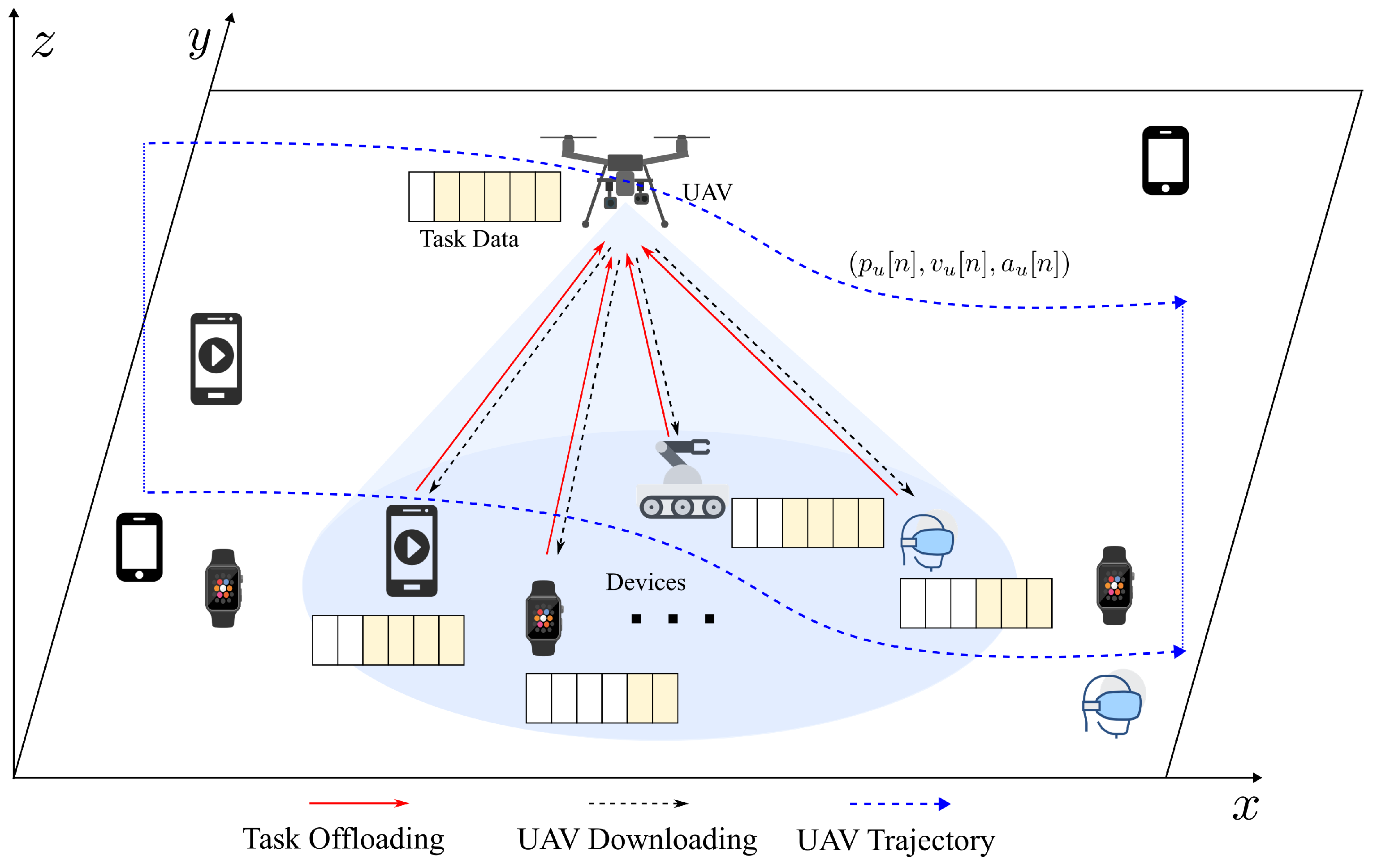
For the challenges discussed above, this paper concentrates on performance optimization of the UAV-assisted multi-user MEC system, taking into account UAV flight dynamics constraints and time-varying factors in dynamic scenarios. Specifically, UAVs operating in multi-user scenarios must dynamically control their flight trajectories and user association strategies based on real-time user task requirements and their own flight states. Such dynamic control is critical for performance optimization and operational feasibility. Notably, the system optimization involves both continuous action variables, such as UAV velocities, and discrete action variables, such as user associations, forming a hybrid action space where these variables are interdependent. This study develops a novel proximal policy optimization-based dynamic control (PPO-DC) algorithm, a DRL-based approach, to minimize system consumption by jointly optimizing the dynamic UAV flight trajectory control and user association strategy. The main contributions of this study are outlined below:
A comprehensive system model for UAV-assisted MEC system is mathematically built by introducing the constraints of UAV flight dynamics, where velocity and acceleration cannot be arbitrarily adjusted, along with dynamic factors such as the dynamic communication environment, time-varying user task requirements, and user mobility.
In order to improve the system performance in terms of delay and energy consumption, the joint optimization of dynamic UAV trajectory control and user association is considered, which is formulated as a non-convex optimization problem with discrete–continuous hybrid variables. The formulation provides the foundation for developing an efficient solution, which is crucial for improving system performance in a dynamic environment.
A novel DRL-based dynamic control algorithm, named PPO-DC, is developed to solve the optimization problem. First, the problem is transformed into a Markov decision process (MDP) model. Then, the PPO-DC algorithm is designed to enable the UAV to efficiently and dynamically adjust its flight trajectory, which corresponds to a continuous variable, and its association decision, which corresponds to a discrete variable. This algorithm minimizes the weighted sum of system delay and energy consumption, while tackling the challenging non-convex joint optimization problem and overcoming the complexities introduced by hybrid-action space and dynamic factors in the scenario.
With respect to UAV trajectory control, the proposed PPO-DC algorithm demonstrates notable practical utility and adaptability to dynamic scenarios. Moreover, the system performance in terms of latency and energy consumption under PPO-DC outperforms that of other hybrid-action DRL algorithms or metaheuristics in our simulation. The PPO-DC exhibits satisfactory reward convergence during the training process. These advantages are proved by the simulation results.
The remaining sections are structured as follows. In
Section 2, the system model, including communication model, computation model, user mobility model, and UAV dynamics model, is presented. Then, the problem formulation is presented. In
Section 3, the problem is transformed into an MDP, followed by the design of the PPO-DC algorithm. In
Section 4, simulation results are analyzed.
Section 5 concludes this paper.
3. PPO-DC Algorithm Design
The problem
presents significant complexity due to its non-convex objective function, the presence of both discrete and continuous variables, and the UAV dynamics Equation (
23a), a constraint that is commonly overlooked in existing works. In reality, the acceleration and velocity of UAVs, subject to the system dynamics constraint, cannot be changed arbitrarily. To tackle the complexity, the problem
is reformulated as an MDP, and then, a DRL algorithm named PPO-DC is proposed.
3.1. Markov Decision Process
The problem can be transformed into an MDP, in which the transition to the next state is only dependent on the current state and the action executed by UAV, satisfying the Markov property. By solving the MDP, the agent learns an optimal policy to improve system delay and energy efficiency through sequential decisions on UAV trajectory control and UD association. Formally, the MDP is characterized by the tuple , in which S, A, and R represent the set of states, actions, and rewards, respectively, while denotes the system’s policy. The detailed description of the MDP is given below.
(1) State: The state
encapsulates the critical information needed for decision-making. According to the system model formulated in
Section 2, the sate
is designed to contain the environment information at time slot
n, including UAV’s position, the UDs’ positions, and task requirements of all UDs. The
can be mathematically defined as
(2) Action: The UAV flight trajectory and UD association strategy are expected to be adjusted by the agent in real time. By enabling the agent to output both continuous (i.e., UAV flight velocity) and discrete (i.e., UD association strategy) actions simultaneously, the inherent interdependence between UAV trajectory control and UD association is preserved, thereby enhancing the effectiveness of joint optimization. Moreover, it improves the dynamic responsiveness of the optimization. The action at time slot
n can be defined as
where
denotes continuous variables representing UAV’s velocity in the x- and y-axes.
denotes the discrete variables indicating the association strategy, where
if the UAV is associated with UD
k, and
otherwise.
By taking the action
in environment, the state
transitions to the next state
according to the UAV dynamics model, user mobility model, communication model, and computation model in
Section 2.
(3) Reward: The goal of the algorithm is to optimize the actor network to maximize the long-term accumulative rewards, with the critic network providing an estimate of the advantage function for policy improvement. The reward function provides a basis for calculating the value and advantage functions, which serve as feedback for refining the policy during training. Through iterative updates of the policy using the clipped objective and advantage estimates, the agent learns an optimal strategy for UAV flight control and UD association. The reward of a state–action pair
can be defined as
where
denotes the penalty, which results from situations where the UAV violates the restricted airspace boundary or the task data amount exceeds the UD’s cache capacity.
At each time step, the agent collects the current environment state and selects the action depending on its learned policy . After the execution of action , the agent observes the next environment state and receives the reward . The iterative process enables the agent to refine its policy to maximize the expected cumulative reward.
3.2. Algorithm Description
Traditional algorithms usually address the issue of UAV trajectory design through iteration methods, which have high computational complexity and low adaptability, rendering them unsuitable for dynamic scenarios with stringent real-time requirements. In comparison, DRL-based algorithms have demonstrated superior performance in solving dynamic decision-making problems. Specifically, while DQN [
42] and A3C [
43] achieve excellent performance, their applicability is limited to discrete action spaces. DDPG [
44], being an offline and deterministic algorithm, is less suitable for real-time control. Within the realm of DRL, PPO [
45] demonstrates satisfactory performance in handling both continuous and discrete action control problems, and outperforms other methods in real-time control applications. Given these considerations, this paper adopts PPO as the fundamental framework for algorithm design, with the proposed algorithm enabling simultaneous control of discrete and continuous actions to dynamically optimize the trajectory and user association, thereby improving system performance. Specifically, the PPO-clip [
45] is utilized, which is one of the recently recommended algorithms by OpenAI [
46]. By leveraging a simple clipping mechanism, PPO-clip constrains policy updates within a predefined range, preventing excessively large policy shifts that could lead to instability. In contrast to the PPO-penalty algorithm, which incorporates a KL penalty and was introduced by Google DeepMind [
47], PPO-clip eliminates the need to manually adjust the KL divergence, making it more suitable for rapid experiments. The work [
45] reported that the clipped surrogate objective outperforms the KL penalty version. Additionally, PPO-clip eliminates the computational overhead imposed by the constraint in the TRPO algorithm [
48], thereby enhancing data-sampling efficiency, improving robustness, and simplifying hyperparameter selection. This makes PPO-clip a widely adopted choice in reinforcement learning applications, particularly in scenarios where both stability and computational efficiency are critical.
The architecture of the PPO-DC algorithm is depicted in
Figure 2. The PPO-DC model comprises an actor network and a critic network, with parameters denoted by
and
, respectively. Two convolutional neural networks (CNNs) with identical structures are separately assigned to the actor and critic networks as feature extractors. The CNNs process the current environment state into a compact feature representation. The input to the CNNs is a three-dimensional tensor, where the first channel records the spatial coordinates of UDs, the second channel stores the current task data amounts of each UD, and the third channel represents the UAV’s position. This structured encoding allows the network to effectively capture spatial correlations and task dynamics. The CNN feature extractor consists of three convolutional layers, where the first, second, and third layers apply 32 filters with kernel size
and stride 4, 64 filters with kernel size
and stride 2, and 32 filters with kernel size
and stride 1, respectively. Each convolutional layer is followed by a ReLU activation and batch normalization. After convolutional processing, the feature maps are flattened and passed through a fully connected layer to produce a 512-dimensional feature vector, which is subsequently fed into both the actor and critic networks. The actor network branches into two parallel heads, a categorical distribution head implemented by a linear layer mapping the 512-dimensional feature vector to 2 logits for discrete user association actions, and a diagonal Gaussian distribution head implemented by a linear layer mapping the feature vector to a 2-dimensional vector representing the continuous UAV velocity control actions. In parallel, the critic network applies a single linear layer to map the 512-dimensional feature vector to a scalar state-value estimation. Through this feature extraction and parallelized actor–critic architecture, PPO-DC efficiently optimizes hybrid discrete–continuous policies.
Following the notations in [
45], the network parameters are updated through gradient ascent to optimize the objective function
, formulated as
where
,
, and
denote the clipping coefficient, hybrid-action probability ratio, and advantage estimation, respectively.
The clipping function
constrains policy updates by ensuring that the probability ratio remains within
, thereby preventing excessive deviations between the new and old policies. When
exceeds this range, the advantage function
is clipped accordingly, thus stabilizing the training. The hybrid-action probability ratio
can be derived as
where the fraction
is the continuous action probability ratio, the fraction
is the discrete action probability ratio, and
is the weight factor.
The advantage estimation
can be derived as
where
,
, and
denote the discount factor, generalized advantage estimation (GAE) weight, and temporal difference error (TD-Error), respectively.
The
can be derived as
where
denotes the value function, which can be derived as
The parameters
of the policy network are updated after each episode by applying the stochastic gradient descent (SGD) method and the gradient
as follows.
where
denotes one mini-batch of time-step indexes and
is the learning rate for actor optimization.
The value loss function
is derived as
where the target value of TD-Error is
.
The critic network parameters are updated by SGD algorithm with
as follows.
where
is the learning rate for the critic network model optimization.
To implement these updates, a complete trajectory is first collected during each episode. This trajectory is then divided randomly into M mini-batches, denoted . Within each mini-batch (for ), the quantities , , , and are computed for each transition . Then, the gradients are derived over and the and are updated.
As explained above, the PPO-DC algorithm optimizes the action decision strategy. Based on this, the PPO-DC algorithm is developed to address the joint optimization of dynamic UAV trajectory control and UD association strategy, with the detailed steps provided in Algorithm 1.
| Algorithm 1 PPO-DC algorithm for dynamic UAV trajectory control and UD association |
- Initialize the Actor model parameters
; - Initialize the Critic model parameters
; - 1:
for Episodes = 1,... do - 2:
Reset the environment; - 3:
Initialize the observed state ; - 4:
for each do - 5:
Gather the current state ; - 6:
Obtain the continuous action distribution from Actor; - 7:
Obtain the discrete action distribution from Actor; - 8:
Sample and Output the hybrid action from Actor; - 9:
Start to execute the action ; - 10:
Obtain the reward and the state when the action is executed; - 11:
Store the transition into the trajectory . - 12:
end for - 13:
for each epoch do - 14:
Divide the trajectory randomly into M mini-batches ; - 15:
for each mini-batch , do - 16:
for each transition do - 17:
Obtain from Critic; - 18:
Derive the temporal difference error and the advantage ; - 19:
Derive the objective function and value loss function ; - 20:
end for - 21:
Compute the aggregated gradient over the mini-batch : - 22:
Update the Actor parameters: - 23:
; - 24:
Compute the aggregated gradient over the mini-batch ; - 25:
Update the Critic parameters; - 26:
; - 27:
end for - 28:
end for - 29:
end for
|
4. Simulation Results
In this section, a thorough evaluation of the PPO-DC is presented. The convergence performance and learning rate are examined initially. The UAV trajectory under flight dynamics constraints is then evaluated, followed by delay and energy consumption performance compared to other state-of-the-art hybrid-action DRL algorithms or metaheuristics.
In the simulation, the UDs and the UAV move within a rectangular service area
of 160 m × 160 m and the UAV flies at an altitude of 10 m above the ground level. The starting position of the UAV is the center of the area, while the initial velocity and acceleration are both set to 0. The maximum UAV flight velocity in x- and y-axes is
= 15 m/s. Each UD moves at a velocity ranging from 0 to 2 m/s. The transmit power of UD is set to 20 dBm. The uplink carrier frequency
is set to 2 GHz. The uplink bandwidth
B is set to 1 MHz. The duration of one time slot is set to 0.1 s. At each time slot, each UD randomly generates a task data amount that follows a Poisson distribution with an expectation of 0.05 Mbits, and the generated amount is truncated to lie within the range [0.01, 0.1] Mbits. The main simulation parameter settings are presented in the
Table 1, unless otherwise indicated. The key hyperparameter of the PPO-DC algorithm such as the learning rate is set to 0.0001 if undefined, the reward discount factor
is 0.99, the clipping coefficient
is 0.1, and the weight factor
of hybrid-action probability ratio is 0.5. Additionally, during agent training, we set up to 4000 time slots per update and utilized eight parallel environments to enhance training efficiency.
4.1. Simulation Parameter Setting
4.2. Convergence Performance
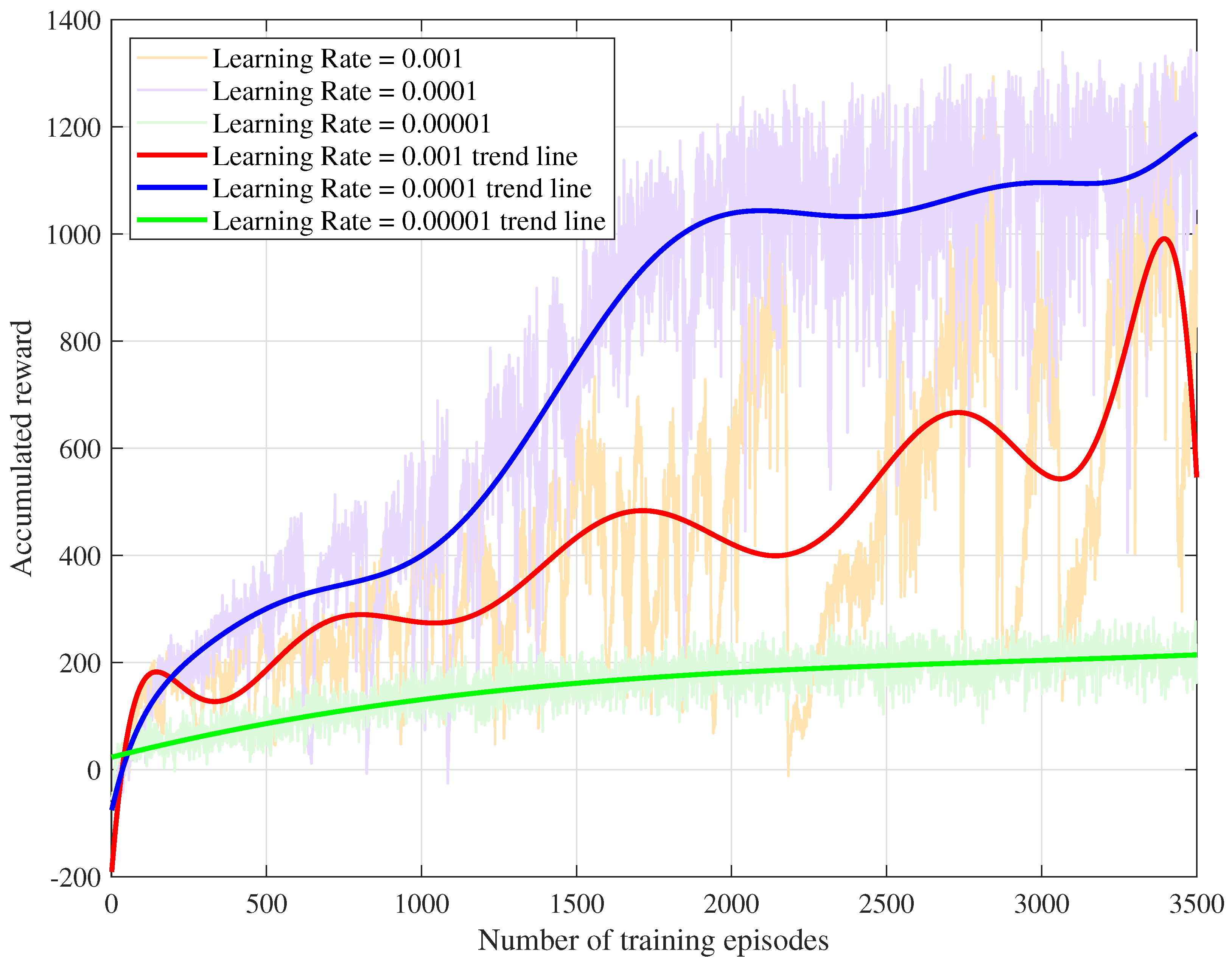
In
Figure 3, the training cumulative reward lines for the PPO-DC algorithm are illustrated under learning rates of 0.001, 0.0001, and 0.00001. It is evident that the learning speed of the agent decreases as the learning rate reduces. If the learning rate is set to 0.001, the agent is capable of learning quickly and achieving a higher cumulative reward than the 0.00001 case. However, the convergence behavior is highly unstable, as evidenced by frequent fluctuations in the cumulative reward line, where the reward often drops sharply after reaching a high value and then rapidly recovers. This instability renders it less practical for reliable training. In contrast, when the learning rate is 0.00001, the agent exhibits significantly more stable convergence, but the learning speed is extremely slow. The agent requires a large number of episodes and updates to achieve a relatively high reward, making it less efficient for practical training scenarios. With a learning rate of 0.0001, the agent achieves the highest cumulative reward among the three cases. The agent converges rapidly to a high reward level while maintaining intermediate stability compared to the other learning rates. Despite minor fluctuations in the reward line, the convergence trajectory remains relatively steady, indicating a robust balance between learning efficiency and stability.
4.3. UAV Trajectory Evaluation
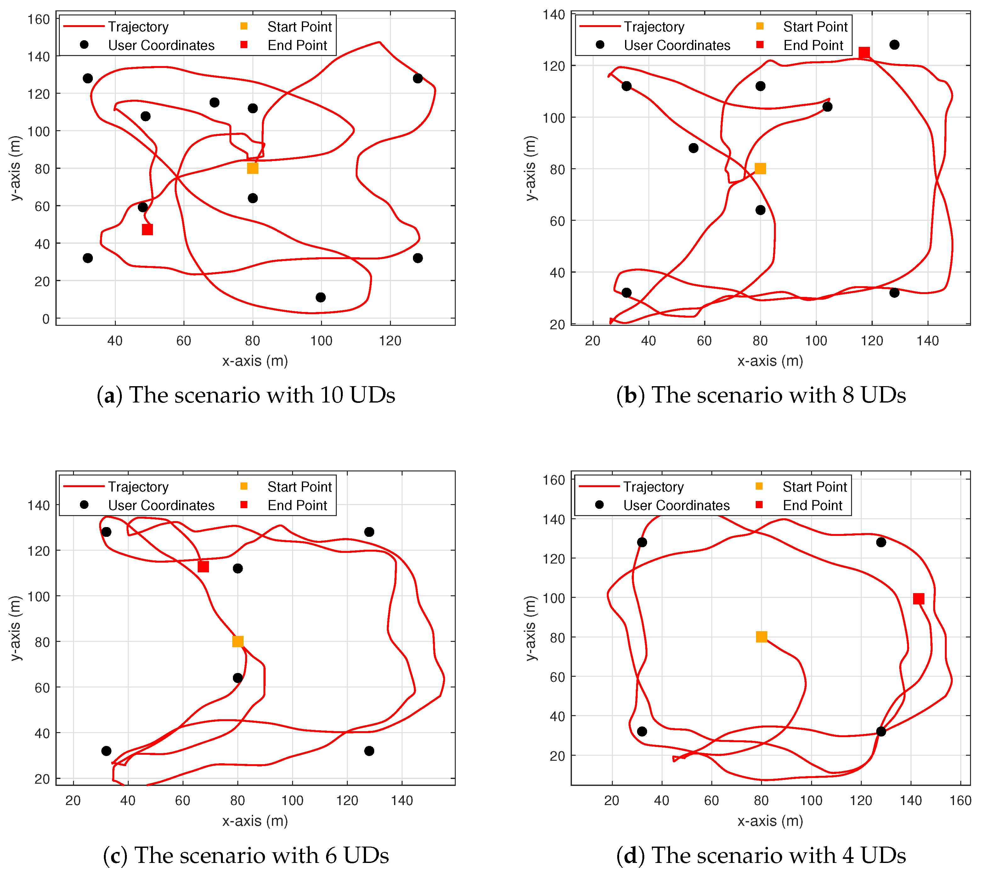
To evaluate the effectiveness of the PPO-DC algorithm in dynamic UAV trajectory control under dynamics principle constraints, the UAV trajectories in scenarios with varying numbers of UDs are first presented in
Figure 4. Subsequently, the comparisons with the PPO algorithm without dynamics constraints are depicted in
Figure 5,
Figure 6 and
Figure 7, focusing on the UAV trajectory, x-axis velocities, and y-axis velocities, respectively.
As demonstrated in
Figure 4, the UAV flight trajectories are effectively controlled by the agent in the scenarios in which MEC services are provided to 4, 6, 8, and 10 UDs, respectively. Specifically, in these scenarios, the UAV flight trajectory is dynamically adjusted based on the distribution of UDs within the service area and UD task requirements. As the density of UDs increases, the algorithm ensures that the UAV flight trajectory remains both feasible and efficient. This demonstrates the scalability of the PPO-DC algorithm in environments with varying UD densities.
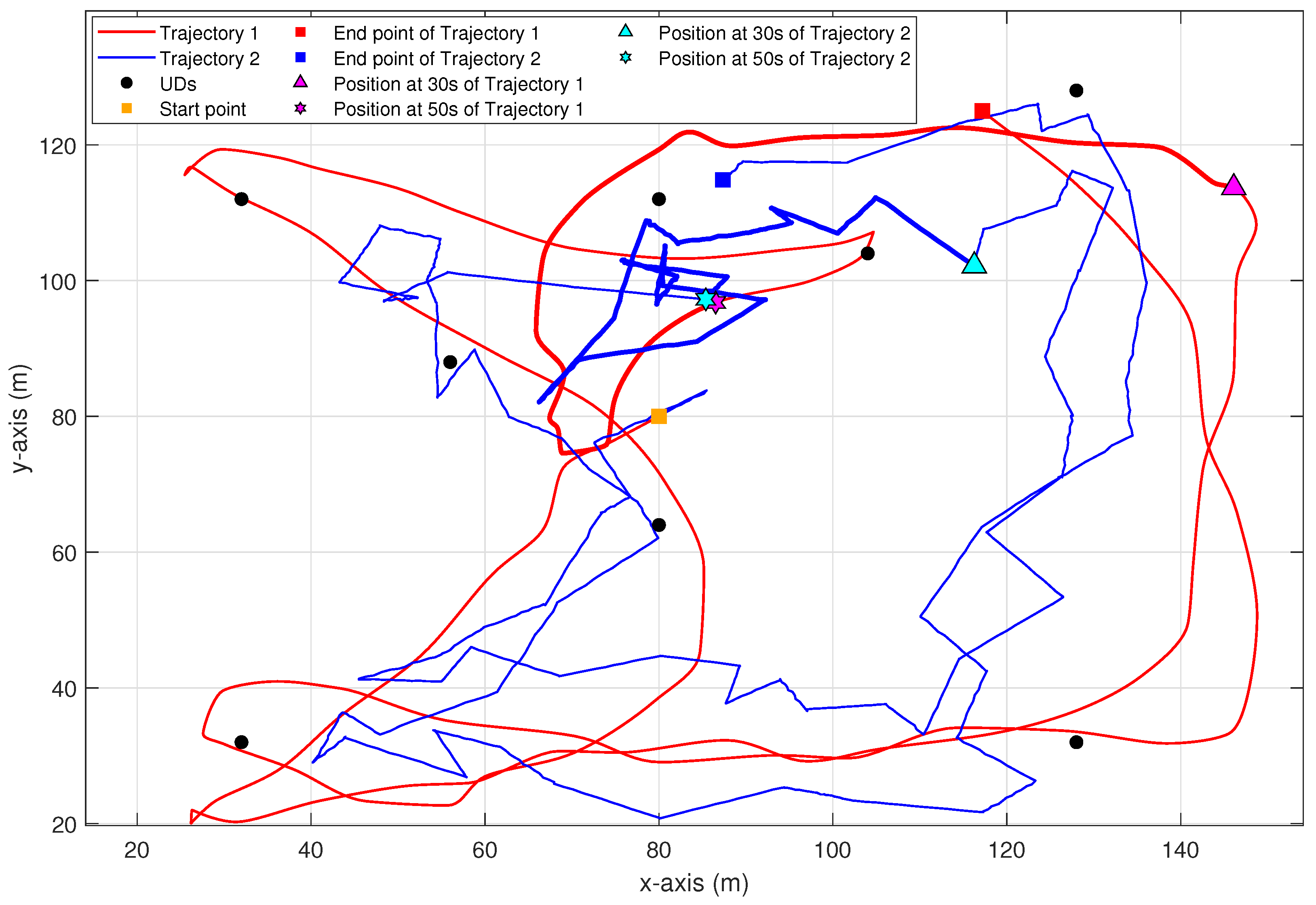
Figure 5 compares the UAV flight trajectories controlled by two different algorithms over a time period of 0 to 100 s in the scenario with eight UDs. Trajectory 1, controlled by the PPO-DC algorithm, which takes into account the flight dynamics constraints, corresponds to the red line. Trajectory 2, controlled by the PPO algorithm without considering flight dynamics constraints, corresponds to the blue line. Although both algorithms adaptively respond to the spatial distribution and task requirements of UDs, their resulting trajectories differ significantly. In particular, trajectory 1 demonstrates a variety of flight actions, including sustained approximate straight movements, smooth turns (e.g., in the lower-right area and upper-right area), sharp turns (e.g., in the lower-left area and upper-left area), semicircular arcs, and U-turns (e.g., in the lower-left area). Each kind of flight action involves continuous changes in direction and velocity, achieved through gradual deceleration before turning and acceleration afterward, which reflects strict compliance with UAV dynamics principles. The thickened portion of trajectory 1, representing the flight trajectory from 30 to 50 s, exhibits a gradual deceleration and acceleration behavior, which is further substantiated by the velocity variations shown in
Figure 6 and
Figure 7. These behaviors collectively illustrate the ability of PPO-DC to generate physically feasible trajectories of UAV across diverse motion contexts in the MEC scenarios. By contrast, trajectory 2 contains sudden direction changes without appropriate velocity adjustments, including many sharp turns executed instantaneously. Such actions violate the fundamental flight dynamics and are infeasible in practical deployments. This contrast reveals the limitations of idealized trajectory control policy and emphasizes the effectiveness of the PPO-DC approach.
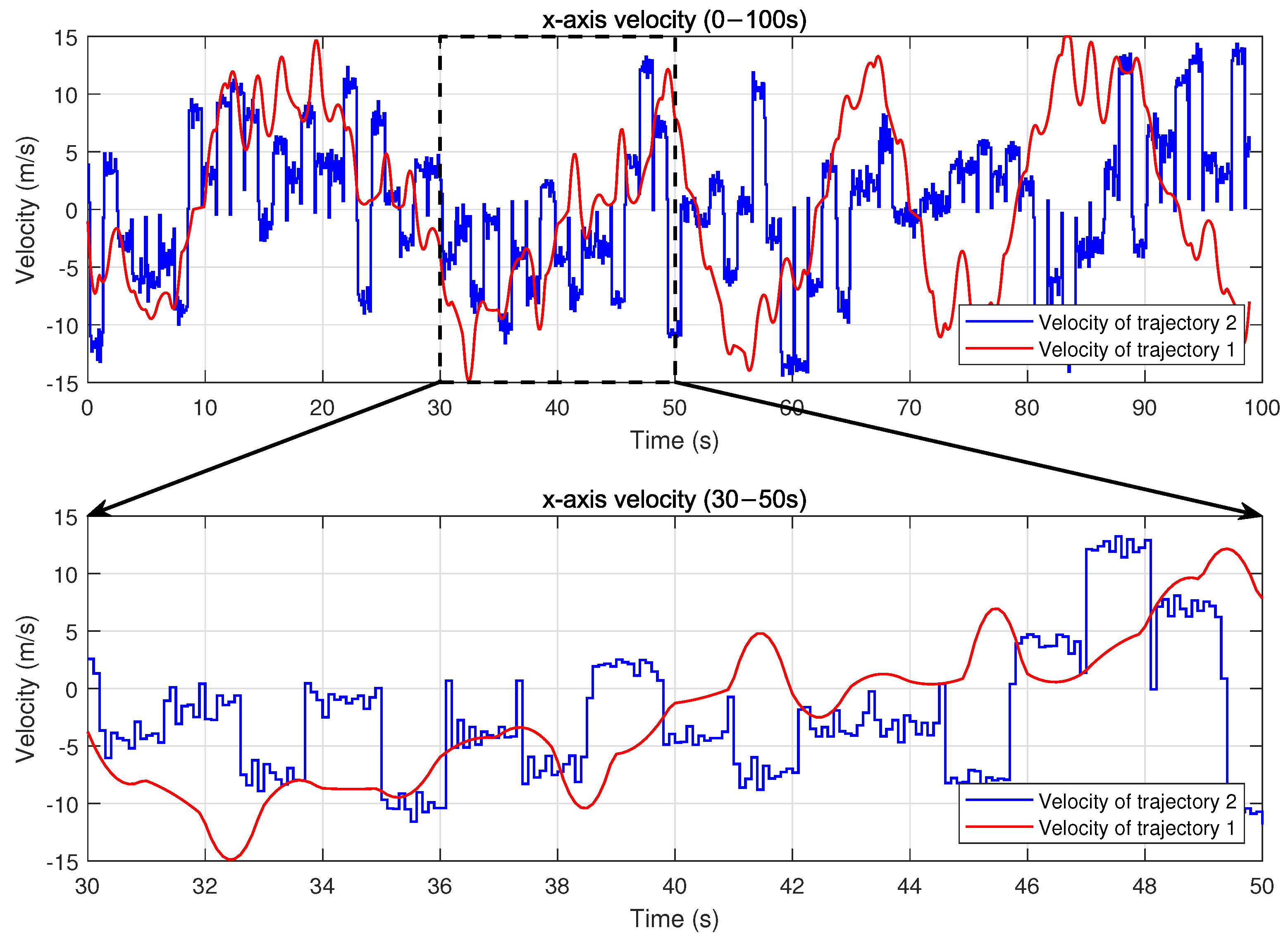
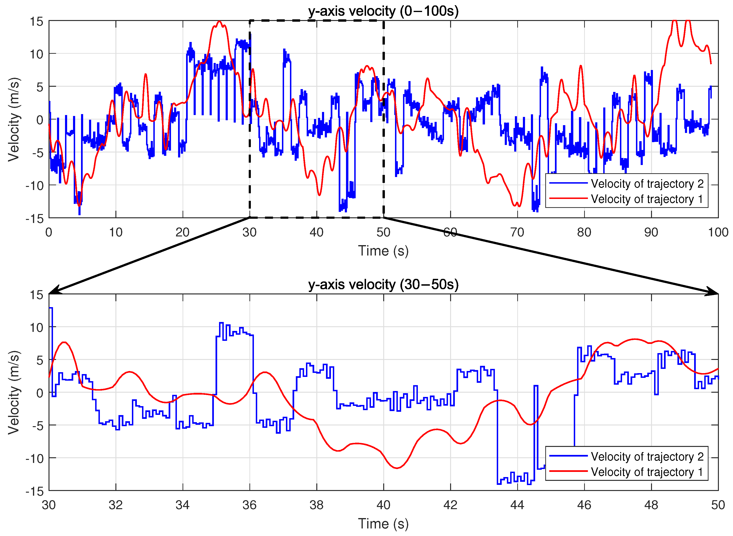
The contrast between trajectory 1 and trajectory 2 is further illustrated in
Figure 6 and
Figure 7, which show the UAV’s velocity changes along the x-axis and y-axis, respectively. In trajectory 2, the UAV experiences sudden jumps or drops in velocity at the beginning of some time slots, reflecting the nature of an idealized control policy that ignores flight dynamics constraints. Specifically, sharp velocity increases can be observed around 34 s and 36 s, where the UAV’s velocity suddenly jumps within a single time slot. Similarly, significant velocity drops occur around 40 s and 48 s. These sudden changes are physically unrealistic for actual UAV platforms, as they violate practical acceleration limits and reveal the lack of dynamics modeling in the baseline PPO algorithm. A zoomed-in view of the interval between 30 and 50 s clearly illustrates these distinctions. By comparison, trajectory 1 exhibits smooth and continuous velocity transitions, which result directly from the PPO-DC algorithm’s explicit consideration of UAV flight dynamics constraints. By embedding these constraints into the control framework, PPO-DC ensures that the trajectories adhere to realistic physical laws, avoiding abrupt changes in velocity and enabling physically feasible flight behavior.
In summary, these observations confirm that PPO-DC not only produces realistic and feasible trajectories but also adapts effectively to complex flight scenarios, including sharp turns, smooth turns, and the transitions between deceleration and acceleration. By considering the dynamics principle, the PPO-DC algorithm provides a more realistic transition of environment states, thereby enhancing the practical utility of the algorithm and its adaptability to dynamic UAV-assisted MEC scenarios.
4.4. Performance Comparisons
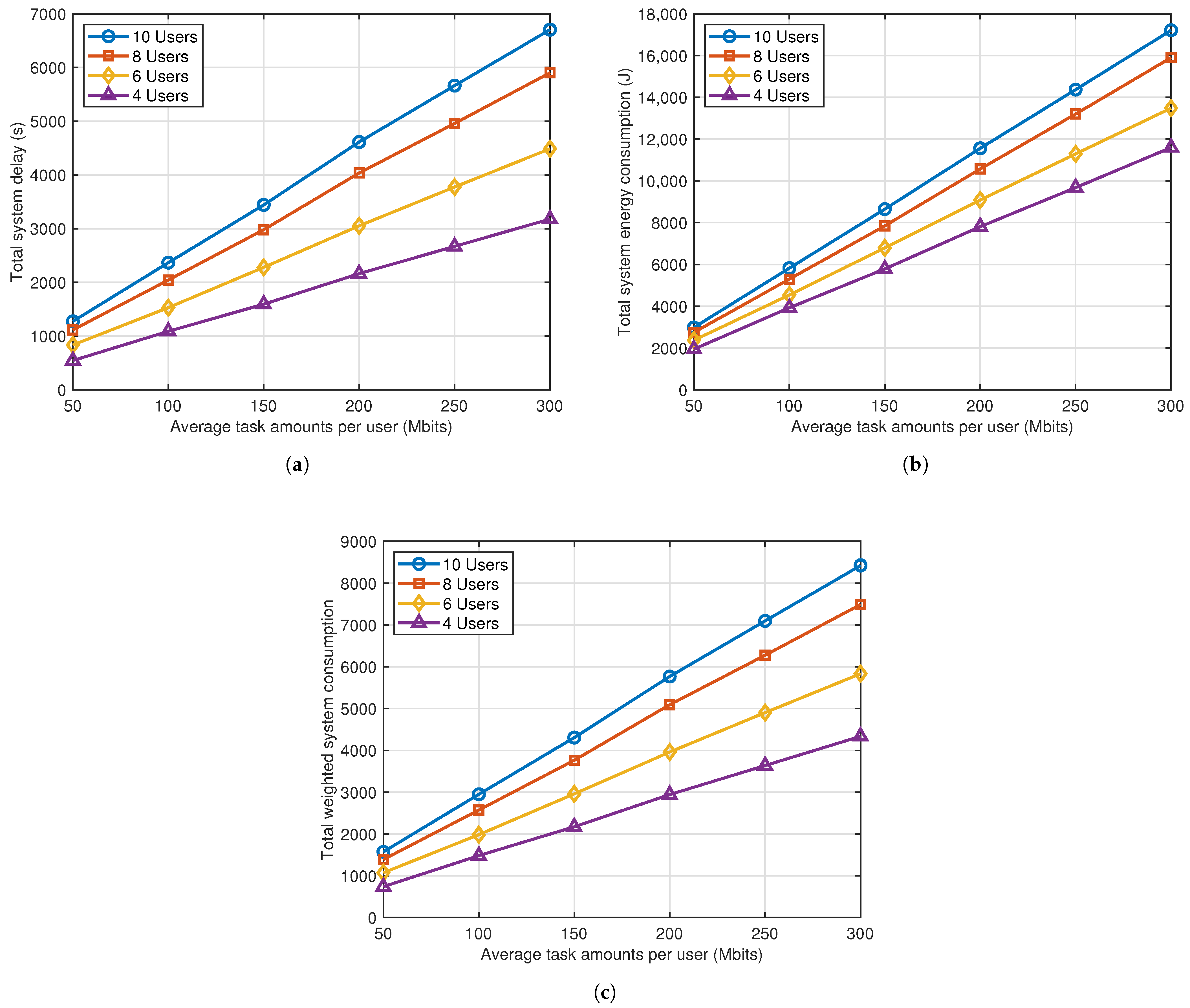
Figure 8 presents the system performance in the scenarios with different numbers of users under PPO-DC, in terms of three metrics, namely total energy consumption, total delay, and total weighted system consumption. The value on the x-axis in
Figure 8 indicates the average task amounts per UD. The figure shows that all three metrics increase as the average task amounts per UD becomes larger, which can be deduced from Equations (
6)–(
11). Additionally, system consumption increases with the number of UDs, as serving more UDs requires more energy and time resources for both computation and data transmission. It is noteworthy that the total system energy consumption in
Figure 8c is the sum of the total system delay and the energy consumption scaled by
. The purpose of introducing the weight parameter
is to modulate the contribution of energy consumption relative to delay, thereby prioritizing the optimization of delay during agent training.
To evaluate the impact of localization errors, zero-mean Gaussian noise with standard deviation values of 0 m, 3 m, 6 m, and 9 m is added to the positions of UDs to simulate measurement uncertainties. The simulation results depicted in
Figure 9 show that as the magnitude of localization errors increases, the system performance gradually deteriorates. This is because inaccurate position estimates disrupt the UAV’s user association and trajectory planning, leading to increased flight distances, higher energy consumption, and longer service delays. The degradation becomes more pronounced under higher UD densities, where smaller distances between UDs amplify the impact of localization noise. The simulation is set to terminate when the processed task data reach 100 Mbits per UD. These findings suggest that in future UAV-assisted MEC systems based on DRL, it would be valuable to explicitly incorporate localization uncertainties into the decision-making framework to further enhance system robustness.
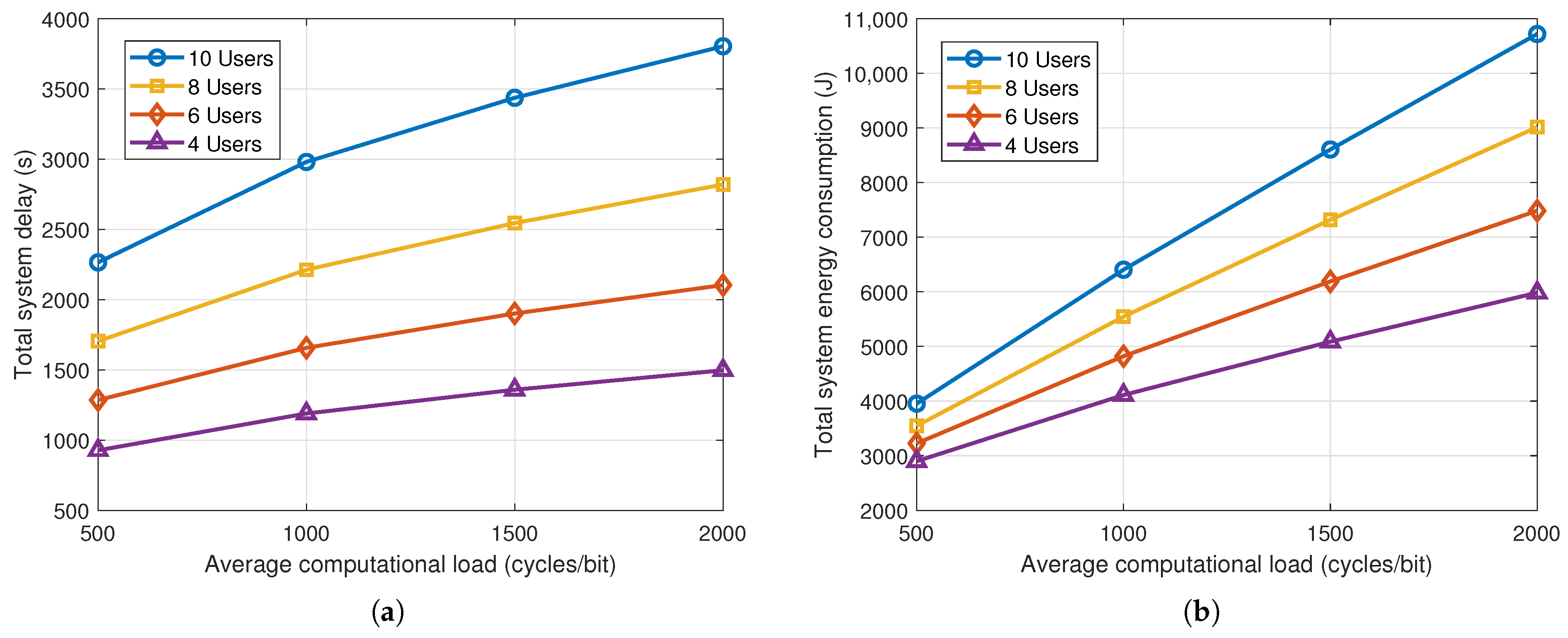
To evaluate the impact of computational load variations, we model the number of CPU cycles required to process one bit of task data as a uniformly distributed random variable centered around four nominal values of 500, 1000, 1500, and 2000 cycles/bit. To capture actual variations in task computing complexity, the computational load per bit of newly generated task data of each user in each time slot is randomly sampled from the
range around the corresponding nominal value. The simulation terminates once all UDs have processed 100 Mbits of data. As shown in
Figure 10, increasing the average computational load leads to significant rises in both system delay and energy consumption. Time-varying computational loads introduce more dynamic processing requirements. This variation challenges the system to maintain stable and efficient scheduling, as processing duration and energy usage fluctuate unpredictably over time. These effects become more pronounced in dense user environments, where the cumulative processing burden further exacerbates delay and energy overheads. These results highlight the necessity of accounting for dynamic computational requirements when evaluating the performance of UAV-assisted MEC systems.
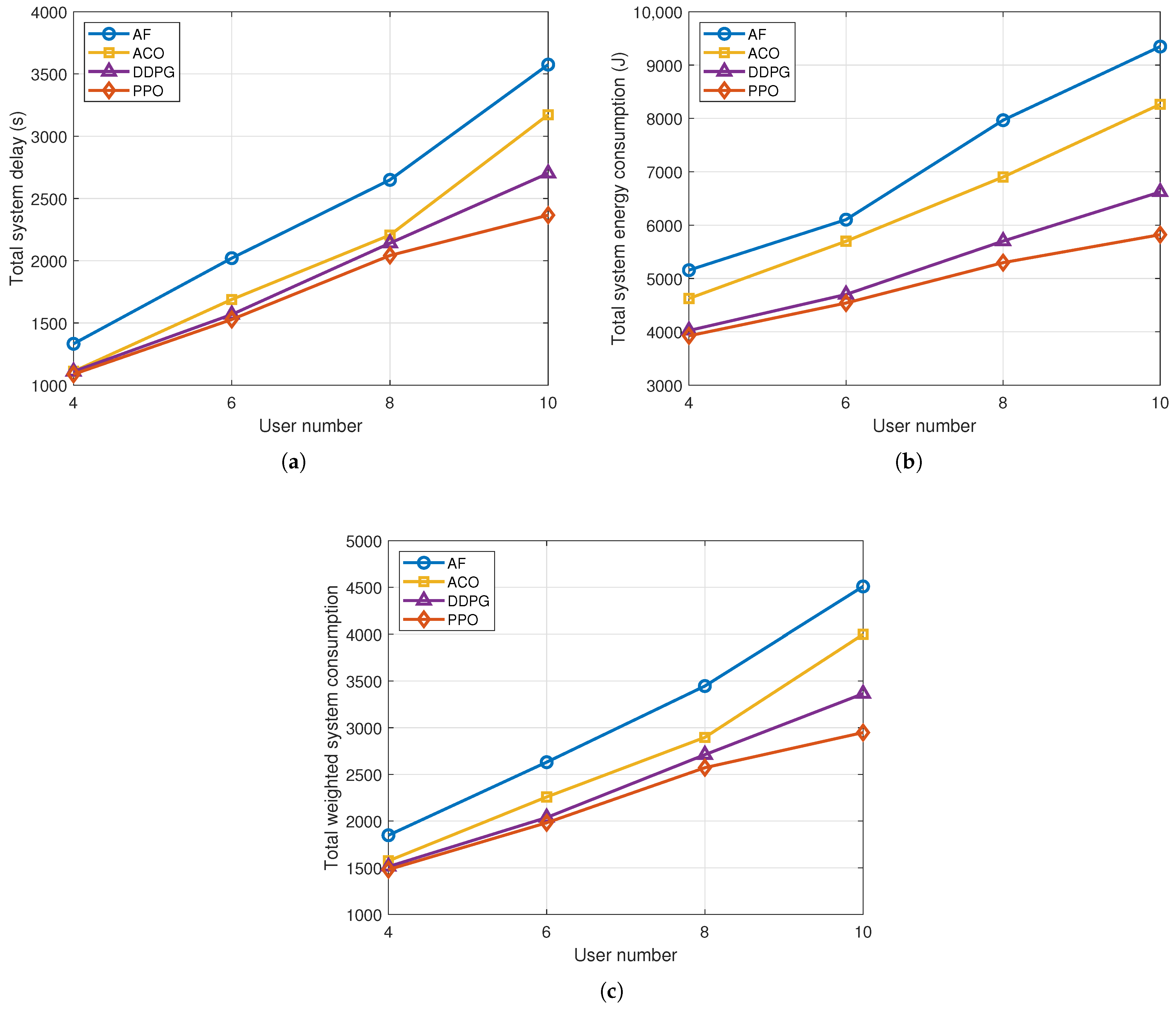
Secondly, to further evaluate the system performance under the PPO-DC algorithm, a comparison is performed between PPO-DC and the following hybrid-action DRL algorithms or metaheuristics:
(1) Ant colony optimization (ACO) strategy: This strategy employs the ACO method to solve a traveling salesman problem (TSP) for UAV trajectory planning. The UAV plans its flight trajectory and UD association by considering both the task requirements and the location distribution of UDs. After completing the trajectory, the UAV replans the optimal trajectory and UD association based on its current position, UD locations, and task requirements.
(2) Around flight (AF) strategy: In this strategy, the UAV associates with the nearest UD based on the shortest distance and flies toward it. The UAV continues to follow this rule to visit all UDs in the service area.
(3) DDPG [
44] strategy: This strategy employs the DDPG algorithm to optimize the UAV’s trajectory control and UD association, which leverages discretization to convert the continuous outputs of the agent to discrete association actions.
The simulation of
Figure 11 is completed when the total computed task data amount reaches 1000 Mbits. In
Figure 11, the total system energy consumption, total system delay, and total weighted system consumption for the different strategies are presented. It can be observed that the PPO-DC strategy exhibits the lowest delay and energy consumption, followed by the DDPG strategy and the ACO strategy, with the AF strategy performing the worst. This is due to the time-varying task requirements and the random mobility of UDs in the scenario, leading to a lack of timeliness of the optimal trajectory planned by ACO strategy. In addition, the AF strategy relies only on distance as the criterion for user association, which leads to poor adaptability to the time-varying task requirements of UDs. The DDPG strategy outperforms the ACO and AF strategies, but demonstrates lower performance compared to PPO-DC. This is because DDPG is designed for continuous action spaces and applies a floor operation to map continuous outputs to discrete UD association actions. This discretization disrupts the smoothness and continuity of the action space, leading to suboptimal decisions. In contrast, PPO-DC directly models and optimizes discrete actions within a hybrid continuous–discrete action framework, and leverages mechanisms such as clipping and entropy regularization to enhance training stability. Benefiting from these advantages, the PPO-DC strategy can dynamically adjust the UAV’s flight trajectory and UD association in real time by considering the UAV flight states, time-varying task requirements, and users’ mobility, thereby achieving superior performance compared to the other strategies.
5. Conclusions
In this paper, the joint optimization problem of dynamic UAV trajectory control and user association is investigated. Considering the UAV flight dynamics constraints and time-varying factors in scenarios, the system model is mathematically constructed. Moreover, the joint optimization is formulated as a non-convex optimization problem with discrete–continuous hybrid variables. To address the challenges posed by the complexity of problems and the dynamics of scenarios, a DRL-based algorithm named PPO-DC is developed. Comprehensive simulation results validate the effectiveness of PPO-DC in convergence rate, dynamic trajectory control, and system overhead reduction, highlighting its significance in enhancing UAV-assisted MEC performance.
Despite these achievements, several research directions remain to be addressed. First, this study focuses on a single UAV scenario, while multi-UAV coordination presents both challenges and opportunities. Future work could extend the proposed framework by considering multi-UAV cooperative user association, simultaneous multi-user computation task processing, and interference management under shared spectrum access, while exploring and developing distributed or federated reinforcement learning methods to address these challenges. Second, the assumption that the UAV has full knowledge of environmental states may not hold in practical scenarios due to incomplete or delayed information. In practice, obtaining complete environmental knowledge requires UDs to transmit their states via wireless links, which incurs overhead, latency, and potential errors. Therefore, exploring the framework of environment state information collection is promising for enhancing practical applicability. Third, LoS channels expose UAVs to security threats such as eavesdropping and jamming. Developing robust security mechanisms is critical to ensure system reliability.


 ,
, 


