Article

Minimum Snap Trajectory Planning and Augmented MPC for Morphing Quadrotor Navigation in Confined Spaces

by
Chaojun Qin
1,
Na Zhao
1,*,
Qiuyu Wang
1,
Yudong Luo
1 and
Yantao Shen
2
1
Department of Computer Science and Technology, Dalian Maritime University, Dalian 116026, China
2
Department of Electrical and Biomedical Engineering, University of Nevada, Reno, NV 89557, USA
*
Author to whom correspondence should be addressed.
Drones 2025, 9(4), 304; https://doi.org/10.3390/drones9040304
Submission received: 12 March 2025 / Revised: 5 April 2025 / Accepted: 10 April 2025 / Published: 12 April 2025

Abstract

:
Existing studies rarely investigate the dynamic morphology factor on motion planning and control, which is crucial for morphing quadrotors to achieve autonomous flight. Therefore, this paper studies the collaborative optimization of trajectory generation and flight control for the morphing quadrotor with real-time adjustable arms. In the motion planning layer, an objective function that combines position and morphology is constructed by embedding variable arm length as a decision variable into the conventional minimum snap trajectory generation framework. The generated trajectory not only satisfies the speed and acceleration constraints, but also smoothly passes through the narrow spaces that are difficult for traditional quadrotors to traverse. In the control layer, a constrained augmented model predictive control based on the dynamics of the morphing quadrotors is proposed to follow the generated trajectory with an embedded integrator, which is added by exploiting the differential flat variables to improve the tracking performance. In the numerical studies, a scenario with a corridor was considered to demonstrate the effectiveness of the proposed control strategy to achieve optimal trajectory under multiple constraints.

1. Introduction

Quadrotors have garnered widespread attention from researchers due to their low cost, simple structure, and high maneuverability [1], making them suitable for various applications, including aerial photography, reconnaissance, and logistics [2]. However, despite their success in open environments, their flight in complex and confined spaces is still limited due to their inability to change shape. This has sparked interest in shape-morphing quadrotors [3,4,5,6,7,8], which can dynamically adjust their airframe during flight to adapt to the environment or can promote their functionality. Currently, research on morphing quadrotors primarily focuses on mechanical design and optimization [9], as well as controller design [10]. Few studies, however, have considered morphological modification.
Compared to conventional quadrotors, morphing quadrotors face the following challenges in terms of motion planning and control [11]. The first one is the lack of consideration for the variable arm. Existing trajectory planning methods typically focus solely on the position of the center of gravity, overlooking changes in the quadrotor’s boundaries, which may lead to collisions when the quadrotor’s size exceeds the width of a confined space and fails to fully utilize the advantages of the morphing system. The second one is the lack of consideration for changes in the inertia matrix and control allocation matrix. During the in-flight morphing process, the system inertia and control allocation matrices change in response to structural changes, resulting in variations in system dynamics and even instability [12]. These problems make the study of path planning and control more challenging than the study of structural design.
Given that there is currently little work that considers morphing factors in motion planning, we primarily introduce methods for conventional quadrotors, which can be categorized into three main approaches: search-based, sampling-based, and numerical optimization-based planning methods [13]. The search-based planning method is represented by the A* algorithm [14], which typically rasterizes the environment, or represents it as a graph, and then utilizes a graph search algorithm to find an optimal path. The sampling-based planning method is represented by rapidly exploring random trees (RRTs) [15], which constructs a path tree or graph by randomly sampling points in the environment and then uses a specific strategy to find a feasible path. This method does not aim to find the optimal path, making it more computationally efficient. In general, the trajectories generated by the above two methods are a combination of a series of broken lines, and the transition between adjacent segments is not smooth, which would cause dynamic fluctuations. The numerical optimization-based trajectory planning method is typically modeled as an optimization problem with constraints on a continuous state space, where the constraints primarily arise from two aspects: the quadrotor and the environment. The optimization objective is, typically, to minimize the expected cost and time of trajectory execution. The trajectory optimization problem is essentially a nonlinear, non-convex optimization problem. There are two commonly used methods: one is the direct solution method; and the other is to transform non-convex optimization problems into convex optimization problems, such as quadratic programming problems and quadratic-constrained quadratic programming problems. The direct solution method typically addresses the original non-convex optimization problem directly and finds the local optimal solution through numerical optimization techniques, such as gradient descent and Newton methods. The advantage of this type of method is that it can handle complex nonlinear constraints and objective functions. However, due to the nature of non-convex problems, the solving process may fall into local optima, and computational efficiency may be low. Another approach is to transform the original problem into a convex problem by introducing slack variables, convex approximations, or reparameterization. The advantage of convex optimization problems lies in their unique global optimal solution and efficient solving ability. As a representative, the minimum snap trajectory generation algorithm proposed in [16] can generate smooth and energy-efficient trajectories by minimizing the trajectory jerk. It represents trajectories as piecewise polynomials with constraints, including trajectory continuity, starting and ending states, and constraints, such as obstacles or dynamic constraints. In this form, the minimum snap problem is transformed into a convex optimization problem, allowing for the global optimal solution to be found using convex optimization solvers.
Path planning technology addresses the problem of trajectory generation for a quadrotor, while the actual flight performance highly depends on the control system’s performance. Currently, researchers have proposed quite a few controllers for morphing quadrotors. A review work [17] provided a detailed summary; here, we introduce several typical controllers. In our previous work [3], we proposed a novel deformable quadrotor based on scissor-like structures, which allows the quadrotor’s volume to be dynamically adjusted to accommodate obstacles of various sizes. To further enhance the adaptability and versatility of the quadrotor, we proposed a novel deployable quadrotor aerial gripper that does not require the integration of extra manipulators [9]. To control these morphing quadrotor systems and to test the benefits of morphing, PID was used for automation. Desbiex et al. [18] proposed a foldable quadrotor that can change to an X-shape during flight, and they designed an adaptive model reference adaptive control (MRAC) strategy to adjust the quadrotor’s attitude and shape in real-time to cope with dynamic changes and uncertainties. Falanga et al. [5] proposed a quadrotor whose shape can transform from the conventional configuration to other shapes (e.g., H, O, and T morphology) in order to adapt to different conditions and operational requirements. Experiments, such as narrow gap crossing, grasping, and transporting, were performed using a linear quadratic regulator (LQR) with adaptive morphology online gain updates. However, performing these tasks in the field can be challenging due to the lack of full six-degree of freedom (DOF) control [17]. Yang et al. [19] developed an origami-based foldable quadrotor, whose arm length can change through a wire-driven mechanism. A feedback controller was designed to ensure stability when the arm changes. In general, most controllers have the following issues: (i) they solve the problems within a fixed window instead of dynamically solving according to current states, such as LQR [5]; (ii) they have not considered the dynamic changes caused by morphing behavior; and (iii) they cannot independently handle multiple constraints, such as PID [9], adaptive controllers [18], and feedback controllers [19], which require combining with other controllers to address constraints. To tackle these issues, we proposed a MPC for the morphing quadrotor [20], which can handle multiple state variables and control inputs under different constraints and adopt orthogonal functions to approximate the control input sequences to reduce the computational burden. The imperfection of this work is that it only studied the attitude control of the morphing quadrotor in different size states, which is a quasi-static study and lacks full six-DOF control.
In this paper, a custom-built morphing quadrotor was used as our platform, which features an additional DOF, allowing it to transform in addition to the functions of a traditional quadrotor. We considered this DOF in the system dynamics and incorporated it into the path planning and controller. The system architecture of this paper, which employs a layered optimization strategy to achieve trajectory tracking, is illustrated in Figure 1. Firstly, a multi-constraint optimization model was constructed based on the minimum snap algorithm, with the minimization of the position state change rate and arm length change rate as the optimization goal, thus adding continuity constraints to ensure the smoothness of the motion, imposing differential constraints to achieve dynamic feasibility, and combining corridor constraints to ensure the safety of obstacle avoidance. Finally, the optimal trajectory and the corresponding arm length sequence were generated as desired values and fed back to the control layer. Then, the desired Euler angles were obtained through the position controller, combined with the expected servo angle obtained from the arm dynamics model, and then input into the attitude loop to acquire the torques and subsequent control allocation. The contributions of this work are as follows: (i) We introduced the morphological factor into the minimum snap trajectory optimization framework and added the quadrotor’s variable arm length as an optimization variable to find an optimal trajectory and arm length. To the best of our knowledge, this was the first attempt to consider the morphing variables in the trajectory optimization framework for the path planning of the morphing quadrotor. (ii) We expanded the work to include full-DOF control based on the augmented model with an embedded integrator in the control to eliminate steady-state error and to ensure accurate trajectory tracking. More importantly, after considering the variable arm length in the path planning algorithm, the obtained quadrotor parameters were dynamically adjusted during flight, which poses an additional challenge compared to the quasi-static work [20].
This paper is organized as follows. Section 2 presents the dynamic model and the augmented MPC controller design based on the custom-built morphing quadrotor. Section 3 details the optimal trajectory generation algorithm, with corridor constraints added and morphology modifications considered. Section 4 demonstrates the trajectory planning and control results based on the numerical studies. Finally, the work is then summarized.

2. Dynamic Modeling and Controller Design

In this section, the dynamic model of the quadrotor, incorporating variable arm-length dynamics, is first established. Then, to simplify the trajectory planning and tracking control design of the system, we give the proof of differential flatness for the morphing system. Finally, a linear parameter-varying augmented state space model is formed to prepare for the MPC-based controller design.

2.1. Dynamic Model of the Morphing Quadrotor

To describe the posture of the quadrotor, we established the world coordinate system o w x w y w z w , the transition coordinate system o c x c y c z c , and the body coordinate system o b x b y b z b , as shown in Figure 2a. The transition coordinate system was obtained by rotating the world coordinate system to the quadrotor’s center of mass by a yaw angle, and then the body coordinate system was obtained through a roll and pitch rotation. Assume that the system center of mass coincides with the origin of the body coordinate system, o b . The dynamic models of the position and attitude loops are briefly given below.

2.1.1. Position Dynamics

Define p = [ x , y , z ] T as the position vector of the quadrotor; thus, we have the corresponding translational dynamics as
m p ¨ = [ 0 0 m g ] T + R [ 0 0 T ] T ,
where m is the mass of the quadrotor, g denotes the gravitational acceleration, T represents the total thrust generated by the four propellers, and R is the rotation matrix of any vector from the body coordinate system to the world coordinate system.
R = c θ c ψ c ψ s θ s ϕ s ψ c ϕ c ψ s θ c ϕ + s ψ s ϕ c θ s ψ s ψ s θ s ϕ + c ψ c ϕ s ψ s θ c ϕ c ψ s ϕ s θ s ϕ c θ c ϕ c θ
where c x and s x denote cos x and sin x , respectively.
Assuming that the attitude angles are small, then (1) can be approximated around the hovering condition as
m p ¨ = [ 0 0 m g ] T + R ¯ [ ϕ θ T ] T ,
where R ¯ = [ 0 m g 0 ; m g 0 0 ; 0 0 1 ] T .

2.1.2. Attitude Dynamics

Define γ = [ ϕ θ ψ ] T as the attitude vector of the quadrotor, and, according to Euler’s equation, the corresponding attitude dynamics can be expressed as
I · ω ˙ = ω × ( I · ω ) + τ ,
where I = d i a g ( I x x , I y y , I z z ) is the inertia matrix, and ω = [ p q r ] T denotes the angular velocity in the body coordinate system, which satisfies the below relationship with the angular velocity in the world coordinate system.
[ ϕ ˙ θ ˙ ψ ˙ ] T = R ˜ [ p q r ] T ,
where R ˜ = [ 1 s ϕ t θ c ϕ t θ ; 0 c ϕ s ϕ ; 0 s ϕ / c θ c ϕ / c θ ] , and t x = tan x . The updated rotation matrix R ˜ can be further simplified to a unit matrix; thus, we have [ ϕ ˙ θ ˙ ψ ˙ ] T = [ p q r ] T . As such, τ = [ τ 1 τ 2 τ 3 ] T is the torque vector, indicating the torque generated by the propeller around the airframe axis, which is
τ 1 τ 2 τ 3 = 0 k F l ^ 0 k F l ^ k F l ^ 0 k F l ^ 0 k M k M k M k M ω 1 2 ω 2 2 ω 3 2 ω 4 2 ,
where k M is the rotor moment constant; k F is the thrust constant of the rotor; ω j , j = 1 , 2 , 3 , 4 , is the motor speed; and l ^ is the arm length of the morphing quadrotor, which is a time-varying parameter and will be identified later.
Then, (4) can be linearized around the operating point as follows:
[ ϕ ¨ θ ¨ ψ ¨ ] T = τ 1 I ^ x x τ 2 I ^ y y τ 3 I ^ z z T ,
where the symbol with hat indicates that the variable is an estimated value.

2.1.3. Identification of Arm Length Dynamics

According to the custom-built morphing quadrotor, it is known that the arm length is controlled by a servo motor. Therefore, the motor rotation angle and arm length correspond to the input and output of the identification model, respectively. According to the geometric relationship illustrated in Figure 2b, we have l 1 = ( l h sin α ) 2 + ( r 1 l h cos α ) 2 , where α is the rotation angle of the servo motor, l h is the radius of the servo horn, and r 1 is the length from the center of servo horn to the central body. Then, we can obtain l ^ = l e + l m + r 1 ( l h sin α ) 2 + ( r 1 l h cos α ) 2 and l m = l 1 + l 2 , where l e is the length of the rod that connects the variable arm and the motor base, l 1 is the length from the center of servo horn to the scissor structure, and l 2 is the length of the variable arm. As l e , l h and r 1 are constants and l m can be measured, the relationship between l ^ and α can be expressed as
l ^ ¨ ( α ) = a l ^ ˙ ( α ) + b l ^ ( α ) + c α ,
where a, b, and c are dimensionless constants that can be obtained through system identification, as indicated in [19]. It is noted that this method can provide us with a rough range, and ultimately, stable control can be achieved by adjusting the control gain.

2.2. Differential Flatness of the Morphing Quadrotor

The theory of differential flatness, by introducing the parametric form of flat outputs, enables the mapping of system dynamics to a low-dimensional subspace, thereby significantly simplifying trajectory planning and control design. Here, we give the proof of the differential flatness for the morphing system, which means that the states and inputs can be expressed as algebraic functions of the carefully chosen flat outputs and their derivatives.
The state vector of the morphing system is given by the position, attitude angle, velocity, angular velocity, and arm length, that is, [ x , y , z , ϕ , θ , ψ , x ˙ , y ˙ , z ˙ , p , q , r , l ] T . We chose the flat output as ξ = [ x , y , z , ψ , l ] T . The input vectors include total thrust T, the torque vector τ , and rotation angle of the servo motor α . Then, a trajectory ξ ( t ) in space can be represented by the flat output, as shown in (9). Clearly, the position [ x , y , z ] T , velocity [ x ˙ , y ˙ , z ˙ ] T , yaw angle ψ , and arm length l can be represented by ξ and ξ ˙ . Next, we will show that other state vectors and inputs can also be represented by ξ and its derivatives.
ξ ( t ) : [ t 0 , t N ] R 3 × S O ( 2 ) × R 1 .
Firstly, to prove that ϕ and θ can be represented by ξ and its derivatives, we introduce the corresponding coordinate axes in (1) as follows:
m p ¨ = m g z w + T z b .
Thus, we have
z b = ε ε , ε = [ x ¨ , y ¨ , z ¨ + g ] T .
The rotation transformation from the world coordinate system to the transition coordinate system can be obtained as x c = [ cos ψ , sin ψ , 0 ] T . From the coordinate system relation illustrated in Figure 2a, y b is perpendicular to the plane formed by x b and z b , which is coplanar with x c and z c , so y b is also perpendicular to x c and z b . Hence, we have
y b = z b × x c z b × x c , x b = y b × z b ,
where z b × x c 0 .
We then have the coordinates of the basis of the body coordinate system in the world coordinate system, which means that (2) can be uniquely determined by (13). Then, ϕ and θ can be uniquely determined.
R = [ x b y b z b ] .
Afterward, we need to prove that the angular velocity can be expressed in terms of ξ and its derivatives. Define the linear acceleration of the quadrotor as a , and take the first-order derivative of (10). Then, we have
m a ˙ = T ˙ z b + ω × T z b .
Substitute T ˙ = m a ˙ z b into (14), and then we can acquire
Γ = ω × z b = m T ( a ˙ ( a ˙ z b ) z b ) .
By substituting the angular velocity ω = p x b + q y b + r z b into (15), we then have
Γ = ω × z b = p y b + q x b .
Therefore, the angular velocity components p, q can be expressed as
p = Γ y b , q = Γ x b .
Note that the angular velocity has the following coordinate transformation relationship: ω = ω b c + ω c w , where ω b c represents the angular velocity of the body coordinate system relative to the transition coordinate system, and ω c w represents the angular velocity of the transition coordinate system relative to the world coordinate system. At the same time, ω b c has no component in the z b direction, so
r = ( ω b c + ω c w ) z b = ψ ˙ z w z b .
Finally, we show that the input can be represented by ξ and its derivatives. Combining (10) and (11), we can obtain T = m ε . As the angular velocity and inertia matrix are functions of the flat output and its derivatives, the control input τ can be calculated from (4). Meanwhile, the rotation angle of the servo motor α can be calculated by (8).
In summary, this section proves the global differential flatness of the system in state-input space by constructing the flat output. This property demonstrates that the entire dynamic behavior of the morphing system can be uniquely parameterized by the flat output and its finite derivatives, thereby reducing the original high-dimensional, nonlinear dynamics constraint to a low-dimensional trajectory planning problem in a flat space. This proof provides theoretical support for the trajectory optimization algorithm in Section 3, which enables the programming problem under complex dynamic constraints to be transformed into a convex optimization problem in flat space.

2.3. Augmented Model Predictive Control

2.3.1. Augmented Model

The state space model of the linear continuous time system is given as follows:
[ p ˙ p ¨ ] T = A 1 [ p p ˙ ] T + B 1 u 1 y = C 1 [ p p ˙ ] T ,
[ γ ˙ γ ¨ ] T = A 2 [ γ γ ˙ ] T + B 2 u 2 y = C 2 [ γ γ ˙ ] T ,
where u 1 = [ ϕ θ T ] T , u 2 = [ τ 1 τ 2 τ 3 ] T , and the combo { A 1 , B 1 , C 1 , A 2 , B 2 , C 2 } are used to define the system in the form of the state-space equation, and the matrices are as follows:
A 1 = A 2 = 0 1 0 0 0 0 0 0 0 0 0 0 0 0 0 1 0 0 0 0 0 0 0 0 0 0 0 0 0 1 0 0 0 0 0 0 B 1 = 0 0 0 0 g 0 0 0 0 g 0 0 0 0 0 0 0 1 m C 1 = C 2 = 1 0 0 0 0 0 0 0 0 0 0 0 0 0 1 0 0 0 0 0 0 0 0 0 0 0 0 0 1 0 0 0 0 0 0 0 B 2 = 0 0 0 1 I x x 0 0 0 0 0 0 1 I y y 0 0 0 0 0 0 1 I z z .
It is noted that the position control loop, described in (19), is a linear time-invariant (LTI) system whose dynamics are independent of the morphing, while the attitude control loop, defined in (20), is a linear parameter-varying (LPV) system whose dynamic characteristics vary with the morphing parameters. The generalized form of (19) and (20) after discretization can be described as
x ( k + 1 ) = A d x ( k ) + B d u ( k ) ,
y ( k ) = C d x ( k ) ,
where the subscript d indicates discretization.
To reduce the steady-state error of the system, we rewrote it in the augmented form by incorporating the integral. Taking a difference operation on (21) and (22), we have
x ( k + 1 ) x ( k ) = A d ( x ( k ) x ( k 1 ) ) + B d ( u ( k ) u ( k 1 ) ) ,
y ( k + 1 ) y ( k ) = C d ( x ( k + 1 ) x ( k ) ) ,
y ( k + 1 ) = C d ( x ( k + 1 ) x ( k ) ) + y ( k ) .
Here, let Δ x ( k + 1 ) = x ( k + 1 ) x ( k ) , Δ u ( k ) = u ( k ) u ( k 1 ) , and Δ x ( k ) = x ( k ) x ( k 1 ) , and then substitute these into (23) and (24) as follows:
Δ x ( k + 1 ) = A d Δ x ( k ) + B d Δ u ( k ) ,
y ( k + 1 ) = C d A d Δ x ( k ) + C d B d Δ u ( k ) + y ( k ) .
Thus, we have an updated state space equation with a new input variable Δ u ( k ) and a new state variable vector x ( k ) = [ Δ x ( k ) T , y ( k ) ] T as follows:
Δ x ( k + 1 ) y ( k + 1 ) x ( k + 1 ) = A d O q y × n x T C d A d E q y × q y A Δ x ( k ) y ( k ) x ( k ) + B d C d B d B Δ u ( k ) y ( k ) = O q y × n x E q y × q y C Δ x ( k ) y ( k ) x ( k ) ,
where O q y × n x is a zero matrix with dimension q y × n x ; E q y × q y is a unit matrix with dimension q y × q y ; n x is the number of states; and q y is the number of outputs.

2.3.2. Output Prediction

Define the sampling time as k, the future state vector as x ( k + 1 ) , x ( k + 2 ) , , x ( k + n y ) , and the future control trajectory as Δ U = [ Δ u ( k ) , Δ u ( k + 1 ) , , Δ u ( k + n u 1 ) ] T , where n u is the control time domain and n y is the predicted time domain, satisfying n u n y . The detailed process of calculating the future state vector and output prediction is described in [21], and it is omitted here. Finally, the output prediction after n y step can be expressed as
y ( k + n y ) = C [ A n y x ( k ) + A n y 1 B Δ u ( k ) + + B Δ u ( k + n y 1 ) ] ,
and the predicted output of each step is Y = [ y ( k + 1 ) , y ( k + 2 ) , , y ( k + n y ) ] T . Then, we have
Y = Px ( k ) + H Δ U ,
where
P = [ CA , CA 2 , CA 3 , , CA n y ] T and H = CB 0 0 CAB CB 0 CA 2 B CAB 0 CA n y 1 B CA n y 2 B CA n y n u B .

2.3.3. Constraints

As the integral term is introduced to reduce the steady-state error, the design of MPC controller needs to consider the constraints on the changing rate Δ u ( k ) in addition to the control variable u ( k ) . For the position loop, as shown in (19), the constraints on the control input u 1 ( k ) = [ ϕ ( k ) θ ( k ) T ( k ) ] T and the corresponding changing rate Δ u 1 ( k ) = [ Δ ϕ ( k ) Δ θ ( k ) Δ T ( k ) ] T need to be considered. Similarly, for the attitude loop, as shown in (20), constraints on the control input u 2 ( k ) = [ τ 1 ( k ) τ 2 ( k ) τ 3 ( k ) ] T and the corresponding changing rate Δ u 2 ( k ) = [ Δ τ 1 ( k ) Δ τ 2 ( k ) Δ τ 3 ( k ) ] T need to be considered. Therefore, at the sampling time k, we have the following generalized constraints formula: u η m i n u η ( k ) u η m a x and Δ u η m i n Δ u η ( k ) Δ u η m a x with η = 1 , 2 .
Considering the sampling times, the maximum and minimum changing rate can be expressed as [ Δ U ( k ) Δ U m a x , Δ U ( k + 1 ) Δ U m a x , , Δ U ( k + n u 1 ) Δ U m a x ] T and [ Δ U ( k ) Δ U m i n , Δ U ( k + 1 ) Δ U m i n , , Δ U ( k + n u 1 ) Δ U m i n ] T , respectively, which can be grouped into the following form:
E E T Δ U Δ U m i n Δ U m a x T ,
where Δ U m i n and Δ U m a x are the column vectors with the same number as the control time domain.
The control input u ( k ) , u ( k + 1 ) , , u ( k + n u 1 ) T can be written in the form that incorporates the input changing rate as C 1 u ( k 1 ) + C 2 [ Δ u ( k ) , Δ u ( k + 1 ) , , Δ u ( k + n u 1 ) ] T , which can be further expressed as
( C 1 u ( k 1 ) + C 2 Δ U ) U m i n ( C 1 u ( k 1 ) + C 2 Δ U U m a x ,
where C 1 = [ E , E , , E ] T and C 2 = [ E , 0 , 0 , , 0 ; E , E ,   0 , , 0 ; ; E , E , E , , E ] .
Combining (30) and (31), we can obtain a linear constraint inequality as
C 2 C 2 E E Δ U U m i n + C 1 u ( k 1 ) U m a x C 1 u ( k 1 ) Δ U m i n Δ U m a x .

2.3.4. Optimization

The purpose of MPC is to minimize the error between the prediction and the reference so that the predicted output at each sampling time reaches the expected reference value. The final result is a series of control inputs Δ U , and then the first obtained control input is returned to the system to make the system reach the reference value. The optimization objective function can be written as J = ( R s Y ) T ( R s Y ) + Δ U T W Δ U , where R s = [ E , E , , E ] T r ( k ) , r ( k ) is the reference value at time k, and W is the diagonal weight matrix of the control input. The final cost function is obtained by solving the first derivative
J = 1 2 Δ U T M Δ U + Δ U T F ,
subject to (32), where M = 2 ( H T H + W ) and F = 2 H T ( R s Px ( k ) ) , which are compatible matrices in the quadratic programming problem.

3. Trajectory Generation with Corridor Constraints

The key to achieving autonomous flight for the quadrotor is to utilize existing information to realize reasonable trajectory planning. As shown in this section, we randomly generated a series of waypoints in 3D space using existing information, and we then calculated the optimal trajectory based on the minimum snap method. This allows the quadrotor to fly from the starting point, pass through the waypoints along the trajectory in sequence, and, finally, return to the starting point. Unlike the trajectory generation of traditional quadrotors, this method leverages the scalability advantage of the morphing quadrotor to achieve better trajectories when navigating narrow corridors.

3.1. Determining Objective Function

Suppose that we have obtained N waypoints through the front-end path planning, then we need to plan them and turn them into a smooth curve. In this work, the polynomial was adopted to express the trajectory, which is defined as σ ( t ) = [ x , y , z , l ] T , where ψ is set to 0 in this study. Thus, we have
σ ( t ) = σ 1 ( t ) = s = 0 n σ s 1 t s , t 0 t < t 1 σ 2 ( t ) = s = 0 n σ s 2 t s , t 1 t < t 2 σ N ( t ) = s = 0 n σ s N t s , t N 1 t t N ,
where t 0 and t N represent the initial time and the end time, respectively; n is the order of the polynomial; and σ i ( t ) denotes the i-th segment with i = 1 , 2 , , N . The time of each segment t can be set freely according to the requirements.
Next, we calculated the parameters σ s i = [ x s i , y s i , z s i , l s i ] T ( s = 0 , 1 , , n ) while satisfying a series of constraints, including equality constraints and inequality constraints. The equality constraints include the fixed waypoints that the quadrotor is expected to pass through, as well as the initial velocity, acceleration, and constraints set to ensure smoothness at the intersection of adjacent trajectories. The inequality constraints include setting the maximum and minimum values of velocity and acceleration, as well as the constraints on the trajectory position and arm length within the corridor area. In addition, the energy consumption during flight is expected to be as minimal as possible; accordingly, the objective function can be modified by minimizing the rate of change in the quadrotor’s position and arm length. Thus, we have the following cost function:
min t 0 t N μ r d k r r d t k r 2 + μ l ( d k l l d t k l ) 2 ,
where position vector r = [ x , y , z ] T , μ r , μ l are dimensionless constants. As τ 1 and τ 2 are functions of the fourth-order derivative of the position, the generated trajectory minimizes the integral of the square of the snap norm, and k r is set to be 4. Similarly, the control input α related to the arm length is presented in the second-order derivative; thus, we have k l = 2 .
The objective function can be transformed into a quadratic programming problem:
min c T H c + f T c s . t . A e q c = b e q A i n e q c b i n e q ,
where c = { x s i , y s i , z s i , l s i } . The equality and inequality constraints can be found in Section 3.2 and Section 3.3.

3.2. Adding Equality Constraints

The equality constraints, including the waypoint constraint, continuity constraint, and differential constraint, are described separately below, with the schematic diagram shown in Figure 3.

3.2.1. Waypoint Constraint

To ensure that the trajectory passes through N waypoints, the following constraints are required:
σ ( t i ) = σ i ,
where σ i = [ x i , y i , z i , l i ] T .

3.2.2. Continuity Constraint

We consider two types of continuity. One is to ensure the continuity of the trajectory, that is, the values at the intersection of the two adjacent trajectories are equal. The other is to minimize snap, which requires the continuity of the fourth-order derivative at the waypoint. Thus, we have
σ i ( κ 1 ) ( t i ) = σ i + 1 ( κ 1 ) ( t i ) ,
where κ 1 = 0 , 1 , 2 , 3 indicates that the κ 1 -th order derivatives are smooth.

3.2.3. Differential Constraint

Continuity constraints ensure that the position, velocity, acceleration, jerk, and snap values are equal at the intersection of adjacent trajectories. Additionally, differential constraints require these values to match predefined setpoints. The general expression can be written as
σ i ( κ 2 ) ( t i ) = σ i ( κ 2 ) ,
where κ 2 = 1 , 2 , 3 , 4 . Generally, the velocity, acceleration, jerk, and snap values for the starting and ending points of the trajectory are set to 0.

3.3. Adding Inequality Constraint

We incorporated the corridor constraints, which account for the variable arm length of the morphing quadrotor, into the inequality constraints of the quadratic programming problem to ensure that the quadrotor can safely traverse the corridor. To this end, we first defined the unit vector from the starting points r i to the end points r i + 1 of the i-th segment as e = ( r i + 1 r i ) / r i + 1 r i . The vertical distance vector d i ( t ) of the i-th segment can be obtained by subtracting the projection component of the vector r i + 1 r i in the direction of the unit vector.
d i ( t ) = ( r ( t ) r i ) ( ( r ( t ) r i ) · e ) e .
The width of the i-th corridor is defined as δ i . To ensure that the path stays within the corridor, it is necessary to satisfy d i ( t ) δ i . Considering that the arm length of the quadrotor changes in flight, there should be d i ( t ) + l i δ i when t i t t i + 1 . By introducing h intermediate points, the inequality constraints are established as follows:
| x w · d i ( t i + ζ 1 + n ( t i + 1 t i ) ) | + l i δ i , ζ = 1 , , h ,
and, equivalently, for y w and z w .

4. Numerical Studies and Results

This section presents the trajectory optimization results of a morphing quadrotor with corridor constraints added and morphology modification considered. A three-dimensional position coordinate and arm length sequence was generated, which were input into the MPC controller and the servo motor that controls the morphing, respectively. The computational unit (HP Z2 Mini G9 Workstation Desktop PC, manufactured by HP Inc., Beijing, China) was equipped with an Intel Core i7-13700 processor and 32 GB RAM. The numerical studies were conducted based on MATLAB R2024b.

4.1. Trajectory Planning Results

4.1.1. Experimental Setup

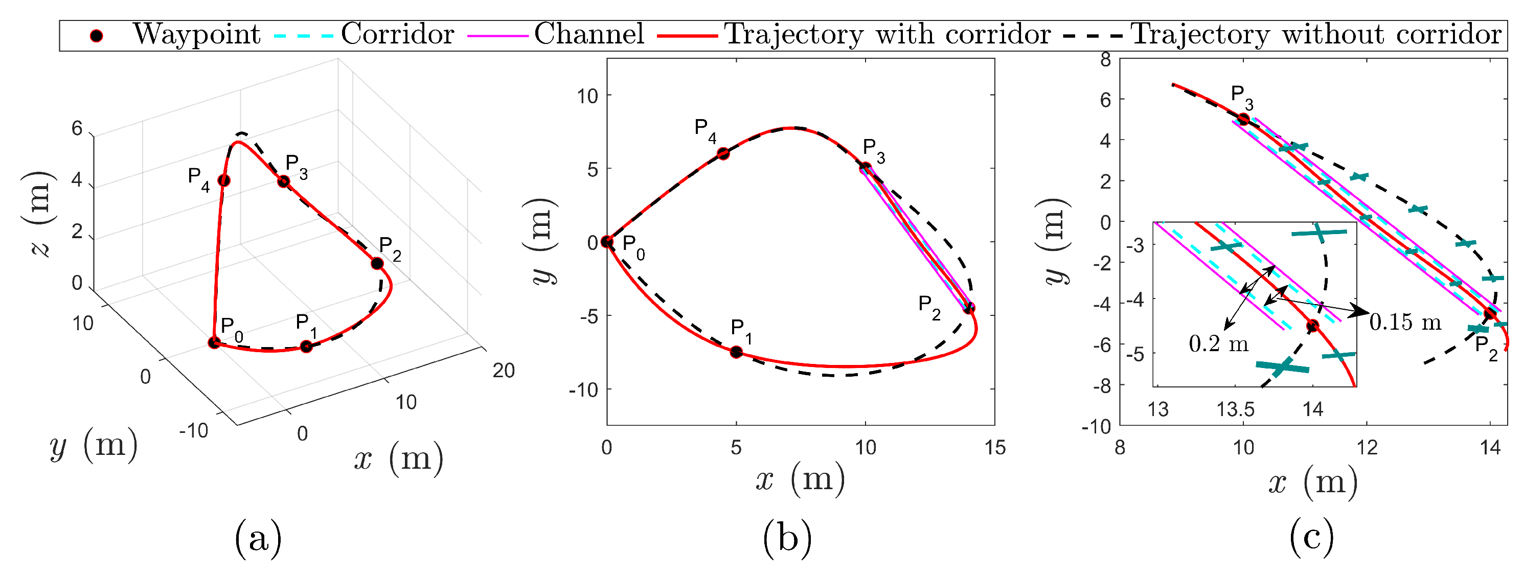
We designed a scenario in which a morphing quadrotor with variable arms needs to pass through N = 5 waypoints and a narrow channel. The positions of these waypoints were randomly set to P 0 = ( 0 , 0 , 0 ) , P 1 = ( 5 , 7.5 , 0.8 ) , P 2 = ( 14 , 4.5 , 2.3 ) , P 3 = ( 10 , 5 , 4 ) , and P 4 = ( 4.5 , 6 , 4.5 ) , respectively, as shown as the black dots in Figure 4a. The narrow channel with a width of D = 0.20 m appeared between P 2 and P 3 , as shown by the magenta solid line in Figure 4b and with the partially enlarged view shown in Figure 4c. Given that there was still a distance from the rotor motor to the quadrotor physical boundary, to ensure the morphing quadrotor could pass through intact, the corridor width was further constrained to δ = 0.15 m ( δ < D ), as shown by the cyan dashed line in Figure 4c. This setting can ensure that, when the quadrotor encounters a narrow channel, it can reduce its size from a larger one to a smaller one to cross. The trajectory, represented by a sixth-order polynomial, starts from P 0 at t 0 = 0 s, sequentially passes through five waypoints with each flight segment lasting 2 s, and then returns to P 0 at t N = 10 s.

4.1.2. Experimental Results

During the simulation process, it was found that the selection of the number of intermediate points h within the corridor in (41) had a significant influence on the result. We employed an exhaustive method to test a series of possible h values and observed the results. When the h value was inappropriate, two types of overshoot would occur. One was constraint violation overshoot, where the arm length exceeded the predefined safety boundary. The other was redundant overshoot, which resulted in an unnecessary increase in arm length due to the suboptimal solution caused by the weight imbalance in the cost function. The above situation will not occur when the h value is appropriate, such as h = 5 and h = 30 . However, as h increases, the time overhead increases, and computational efficiency decreases. Therefore, considering the above factors, a lower value of h = 5 is determined as the optimal number of intermediate points.
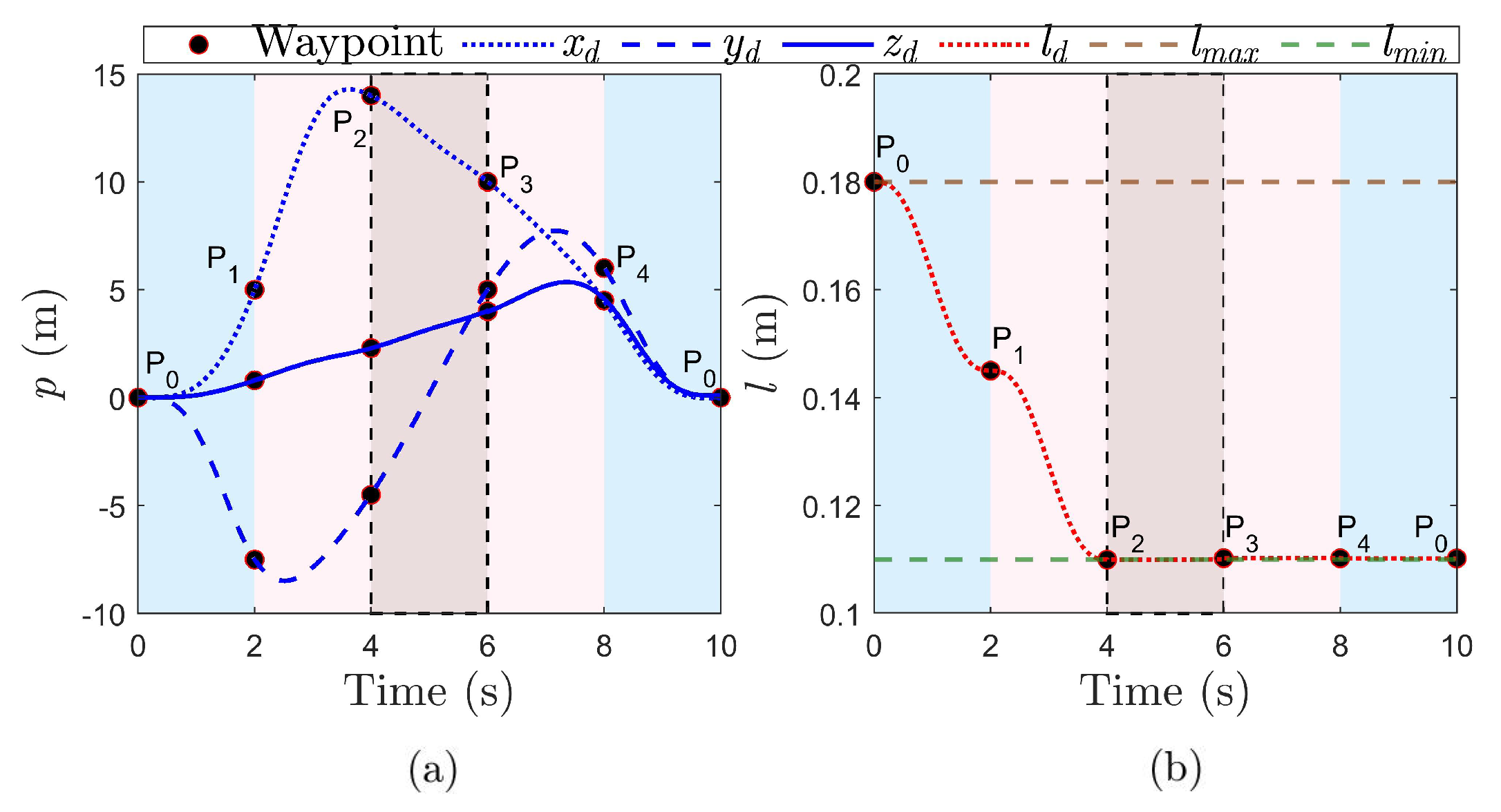
The regular corridor-free trajectory generated by five waypoints is plotted as a black dashed line in Figure 4a–c. When a narrow corridor was added between P 2 and P 3 , the trajectory was replanned to the red solid curve. Figure 5a,b demonstrate the generated position coordinates and the arm length, where the subscript d indicates the replanned information after adding the corridor, which will be used as the desired coordinates for the control. It can be observed that, before entering the corridor, the quadrotor’s arm length was initially 0.18 m, and it then decreased to approximately 0.14 m within the first 2 s, thus optimizing the flight state by shortening the arm length in preparation for the subsequent crossing of the corridor. After a short period of stabilization, the arm length continues to decrease, reaching 0.11 m at t = 3.85 s, which created favorable conditions for crossing the corridor. When t [ 4 , 6 ] s, the quadrotor successfully crossed the corridor with a length of 0.11 m. After that, the arm length remained 0.11 m until the quadrotor returned to P 0 .
The results show that the optimization-based minimum snap trajectory generation method can generate smooth flight trajectories. When considering narrow corridors, by incorporating arm length changes into the optimization objective, the quadrotor is expected to adjust the arm length to safely and stably traverse the confined space without deviating from the trajectory while minimizing position changes and arm length changes, that is, minimizing energy. At this point, we obtained the coordinates of the optimal trajectory and optimal arm length for the morphing quadrotor, [ x d , y d , z d , l d ] , which were then input into the subsequent controller.

4.2. Augmented MPC-Based Controller Results

4.2.1. Experimental Setup

An inner–outer double-loop-augmented MPC controller was designed to realize the trajectory tracking. The trajectory generated above was used as a reference for the outer position loop, the generated control sequence served as a reference for the inner attitude loop, and the generated control input sequence determined the propeller speed. In designing the controller, the parameters and constraints were set as follows: m = 1.6 kg; g = 9.81 m/s2; ϕ , θ [ π 5 , π 5 ] rad; ψ = 0 rad; T [ 0 , 2 m g ] ; [ Δ ϕ m i n , Δ ϕ m a x ] = [ 0.6 , 0.6 ] ϕ m a x , [ Δ θ m i n , Δ θ m a x ] = [ 0.6 , 0.6 ] θ m a x ; [ Δ T m i n , Δ T m a x ] = [ 0.6 , 0.6 ] m g , ω j [ 3093 , 4720 ] rpm; and the prediction horizon and control horizon in the position control and attitude control were both n y = 20 and n u = 3 , respectively. Additionally, a random noise of 0.01 × r a n d ( 1 ) was added to the morphing quadrotor to make it more realistic.

4.2.2. Experimental Results

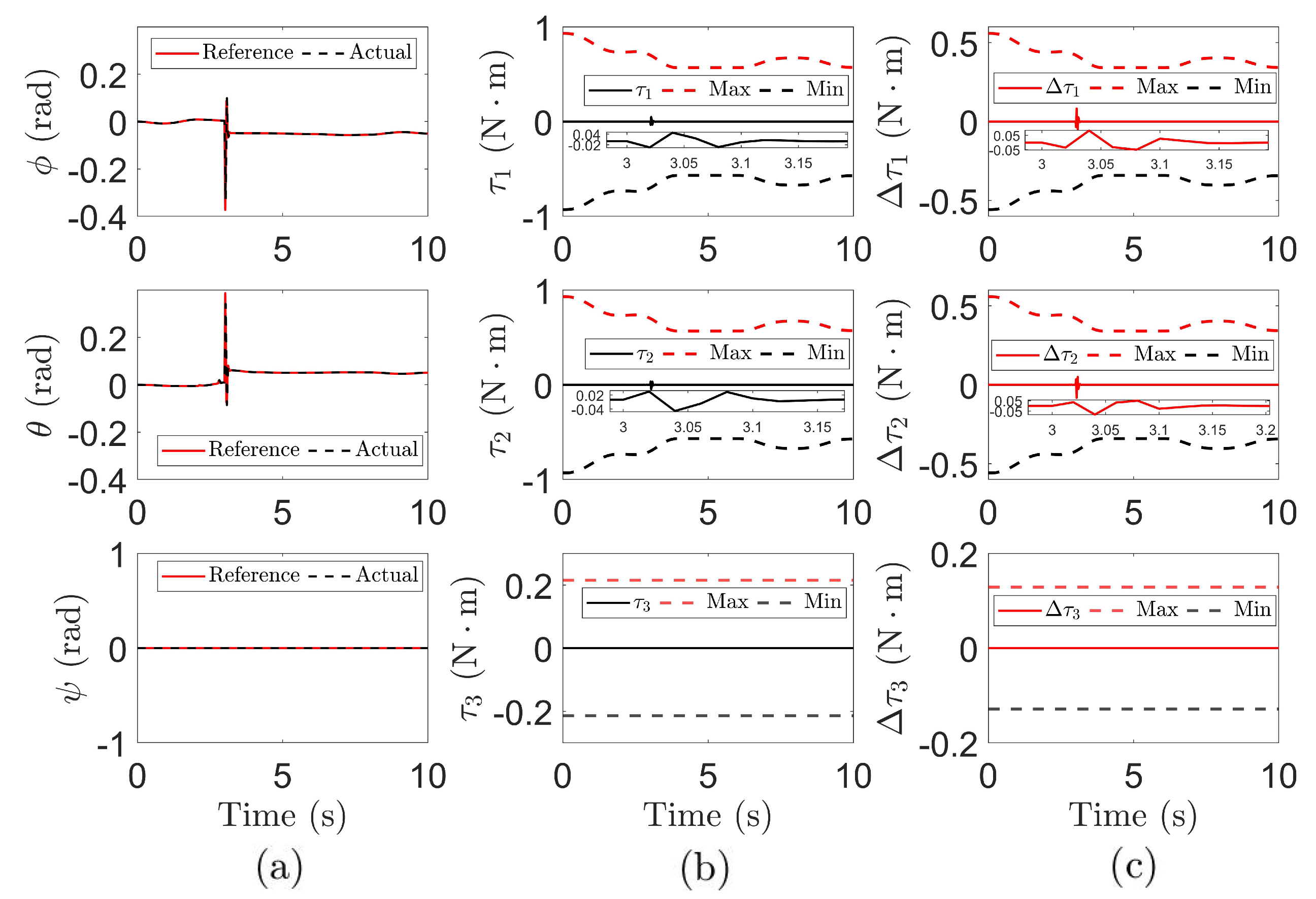
The control results of the position and attitude are shown in Figure 6 and Figure 7. The trajectory generated by the trajectory optimization algorithm in the above step was used as the desired trajectory for the position control in this step, which is represented by the red curve in Figure 6a, with the black dashed line indicating the actual trajectory. It can be seen that, despite the addition of random noise to the system, the position controller was still able to track the desired trajectory coordinates well, with a maximum error of 0.02 m in the x y plane. In addition, Figure 6b,c show the control input required for the outer loop [ ϕ , θ , T ] , and their changing rate [ Δ ϕ , Δ θ , Δ T ] was constrained to their respective fixed ranges (see the dashed lines). It is worth noting that, in order to eliminate the high-frequency jitter caused by noise and system nonlinearity, the control inputs are processed by median filtering. As shown by the solid red line in Figure 6b, the filtered control inputs were relatively smooth, without obvious oscillations or mutations. Then, ϕ , θ , together with the preset ψ , was used as the reference for the inner loop. Similarly, it can be seen from Figure 7a that the attitude controller achieved a high attitude tracking accuracy, with the maximum tracking error being less than 0.006 rad. The control input of the attitude loop was the three-axis torque. It is noted here that, different from the position control, the constraints of the torques and their corresponding changing rate were dynamically adjusted over time due to the variable arm length characteristic, as shown the high bound and low bound curves in Figure 7b,c. Nonetheless, the controller can ensure that the control inputs and their changing rate are always determined within the constraints without exceeding the boundaries. These results demonstrate that the constructed augmented MPC-based controller exhibits tracking accuracy in the presence of random noise, effectively coping with the uncertainty caused by changes in system parameters and thereby proving its adaptive ability.
In summary, the position loop achieved high-precision trajectory tracking despite random noise disturbances, and the attitude loop maintained excellent tracking performance, even in the presence of dynamic variations. These results validate the effectiveness of the proposed dual-loop augmented MPC-based control strategy for the morphing quadrotor system.

4.3. Robustness Test Results

To comprehensively evaluate the robustness of the proposed controller, a series of disturbance increment tests were conducted by adding bidirectional burst disturbances to the position loop at a specific time to observe the system’s dynamic compensation ability in response to external disturbances. The results show that the maximum disturbance amplitude that the system can withstand is ±0.1 m. Therefore, we will representatively demonstrate the system’s response at a certain moment (such as, for example, t = 3 s) when the disturbance amplitude is 0.1 m, as shown in Figure 8 and Figure 9. Overall, in the position loop, the horizontal axis ( x / y ) tracking errors remained stable throughout, while the vertical axis (z) exhibited instantaneous overshoot after disturbance but converged to a steady state within 0.1 s, as illustrated in Figure 8a. For control inputs, we have ϕ , θ , and T, along with their changing rate transient fluctuations due to disturbance compensation demands, but these stabilized within 0.2 s, as shown in Figure 8b,c. In the attitude loop, the attitude angle tracking errors remained within 0.002°, as shown in Figure 9a, validating the high-precision tracking capability of the inner loop. Although torque τ 1 and τ 2 , as well as their changing rate, exhibited overshoot at the disturbance moment, they converged rapidly within 0.2 s without triggering attitude oscillations, as shown in Figure 9b,c. The experimental results demonstrate that the proposed controller effectively blocks disturbance chain propagation while ensuring position tracking accuracy, providing a reliable solution for full-state stability control in dynamic environments.

5. Conclusions

In response to the current research situation, where few morphological modifications have been considered in the motion planning of existing morphing quadrotors, a synergistic framework for trajectory planning and control is proposed to enable the autonomous flight of quadrotors. In motion planning, the arm length variable is integrated into the minimum snap optimization framework to achieve joint optimization of position and morphology. The generated trajectory can circumvent obstacles that cannot be passed by traditional fixed quadrotors by dynamically adjusting the arm length. In terms of control, we designed full-system control based on the augmented model and a dual-loop MPC architecture, with the outer loop tracking the position trajectory and the inner loop synchronizing the attitude and arm length. An integrator was also embedded in the control to eliminate the steady-state error, and precise trajectory tracking of the quadrotor was achieved under dynamic changes in the quadrotor parameters. Additionally, a step disturbance was introduced to verify the system’s robustness.

Author Contributions

Conceptualization, N.Z.; methodology, N.Z., C.Q. and Y.L.; software, C.Q.; validation, C.Q. and Q.W.; formal analysis, C.Q.; investigation, N.Z. and C.Q.; resources, C.Q. and Q.W.; data curation, C.Q.; writing—original draft preparation, C.Q.; writing—review and editing, N.Z., Q.W., Y.L. and Y.S.; visualization, C.Q.; supervision, N.Z.; project administration, N.Z.; funding acquisition, N.Z. and Y.L. All authors have read and agreed to the published version of the manuscript.

Funding

This research was funded by the National Natural Science Foundation of China (under Grant 52305009) and the Fundamental Research Funds for the Central Universities (under Grant 3132024252). The APC was backed by the National Natural Science Foundation of China (under Grant 52305009).

Data Availability Statement

The original contributions presented in this study are included in the paper. Further inquiries can be directed to the corresponding authors.

Conflicts of Interest

The authors declare no conflicts of interest.

Abbreviations

The following abbreviations are used in this manuscript:
PIDProportional-Integral-Derivative
RRTRapidly Exploring Random Tree
LQRLinear Quadratic Regulato
DOFDegree of Freedom
MPCModel Predictive Control
LTILinear Time-Invariant
LPVLinear Parameter-Varying

References

  1. Ollero, A.; Tognon, M.; Suarez, A.; Lee, D.; Franchi, A. Past, Present, and Future of Aerial Robotic Manipulators. IEEE Trans. Robot. 2022, 38, 626–645. [Google Scholar] [CrossRef]
  2. Loianno, G.; Scaramuzza, D. Special Issue on Future Challenges and Opportunities in Vision-Based Drone Navigation. J. Field Robot. 2020, 37, 1–8. [Google Scholar] [CrossRef]
  3. Zhao, N.; Luo, Y.; Deng, H.; Shen, Y. The Deformable Quad-Rotor: Design, Kinematics and Dynamics Characterization, and Flight Performance Validation. In Proceedings of the 2017 IEEE/RSJ International Conference on Intelligent Robots and Systems (IROS), Vancouver, BC, Canada, 24–28 September 2017; pp. 2391–2396. [Google Scholar]
  4. Zhao, M.; Anzai, T.; Shi, F.; Chen, X.; Okada, K.; Inaba, M. Design Modeling and Control of an Aerial Robot Dragon: A Dual-Rotor-Embedded Multilink Robot with the Ability of Multi-Degree-of-Freedom Aerial Transformation. IEEE Robot. Autom. Lett. 2018, 3, 1176–1183. [Google Scholar] [CrossRef]
  5. Falanga, D.; Kleber, K.; Mintchev, S.; Floreano, D.; Scaramuzza, D. The Foldable Drone: A Morphing Quadrotor That Can Squeeze and Fly. IEEE Robot. Autom. Lett. 2019, 4, 209–216. [Google Scholar] [CrossRef]
  6. Wu, Y.; Yang, F.; Wang, Z.; Wang, K.; Cao, Y.; Xu, C.; Gao, F. Ring-Rotor: A Novel Retractable Ring-Shaped Quadrotor with Aerial Grasping and Transportation Capability. IEEE Robot. Autom. Lett. 2023, 8, 2126–2133. [Google Scholar] [CrossRef]
  7. Bucki, N.; Tang, J.; Mueller, M.W. Design and Control of a Midair-Reconfigurable Quadcopter Using Unactuated Hinges. IEEE Trans. Robot. 2023, 39, 539–557. [Google Scholar] [CrossRef]
  8. Xu, M.; De, Q.; Yu, D.; Hu, A.; Liu, Z.; Wang, H. Biomimetic Morphing Quadrotor Inspired by Eagle Claw for Dynamic Grasping. IEEE Trans. Robot. 2024, 40, 2513–2528. [Google Scholar] [CrossRef]
  9. Zhao, N.; Luo, Y.; Wang, G.; Shen, Y. A Deployable Articulated Mechanism Enabled In-Flight Morphing Aerial Gripper. Mech. Mach. Theory 2022, 167, 104518. [Google Scholar] [CrossRef]
  10. Patnaik, K.; Zhang, W. Adaptive Attitude Control for Foldable Quadrotors. IEEE Control Syst. Lett. 2023, 7, 1291–1296. [Google Scholar] [CrossRef]
  11. Xing, S.; Zhang, X.; Tian, J.; Xie, C.; Chen, Z.; Sun, J. Morphing Quadrotors: Enhancing Versatility and Adaptability in Drone Applications—A Review. Drones 2024, 8, 762. [Google Scholar] [CrossRef]
  12. Cui, G.; Xia, R.; Jin, X.; Tang, Y. Motion Planning and Control of a Morphing Quadrotor in Restricted Scenarios. IEEE Robot. Autom. Lett. 2024, 9, 5759–5766. [Google Scholar] [CrossRef]
  13. González, D.; Pérez, J.; Milanés, V.; Nashashibi, F. A Review of Motion Planning Techniques for Automated Vehicles. IEEE Trans. Intell. Transp. Syst. 2016, 17, 1135–1145. [Google Scholar] [CrossRef]
  14. Hart, P.E.; Nilsson, N.J.; Raphael, B. A Formal Basis for the Heuristic Determination of Minimum Cost Paths. IEEE Trans. Syst. Sci. Cybern. 1968, 4, 100–107. [Google Scholar] [CrossRef]
  15. Karaman, S.; Frazzoli, E. Sampling-Based Algorithms for Optimal Motion Planning. Int. J. Robot. Res. 2011, 30, 846–894. [Google Scholar] [CrossRef]
  16. Mellinger, D.; Kumar, V. Minimum Snap Trajectory Generation and Control for Quadrotors. In Proceedings of the 2011 IEEE International Conference on Robotics and Automation, Shanghai, China, 9–13 May 2011; pp. 2520–2525. [Google Scholar]
  17. Patnaik, K.; Zhang, W. Towards Reconfigurable and Flexible Multirotors: A Literature Survey and Discussion on Potential Challenges. Int. J. Intell. Robot. Appl. 2021, 5, 365–380. [Google Scholar] [CrossRef]
  18. Desbiez, A.; Expert, F.; Boyron, M.; Diperi, J.; Viollet, S.; Ruffier, F. X-Morf: A Crash-Separable Quadrotor That Morfs Its X-Geometry in Flight. In Proceedings of the 2017 Workshop on Research, Education and Development of Unmanned Aerial Systems (RED-UAS), Cartagena, Spain, 8–10 November 2017; pp. 222–227. [Google Scholar]
  19. Yang, D.; Mishra, S.; Aukes, D.M.; Zhang, W. Design, Planning, and Control of an Origami-Inspired Foldable Quadrotor. In Proceedings of the 2019 American Control Conference (ACC), Philadelphia, PA, USA, 10–12 July 2019; pp. 2551–2556. [Google Scholar]
  20. Zhao, N.; Luo, Y.; Qin, C.; Luo, X.; Chen, R.; Shen, Y. Attitude Control for Morphing Quadrotor through Model Predictive Control with Constraints. In Proceedings of the 2024 IEEE International Conference on Robotics and Automation (ICRA), Yokohama, Japan, 13–17 May 2024; pp. 10489–10495. [Google Scholar]
  21. Rossiter, J.A. Model-Based Predictive Control: A Practical Approach; CRC Press: Boca Raton, FL, USA, 2017. [Google Scholar]
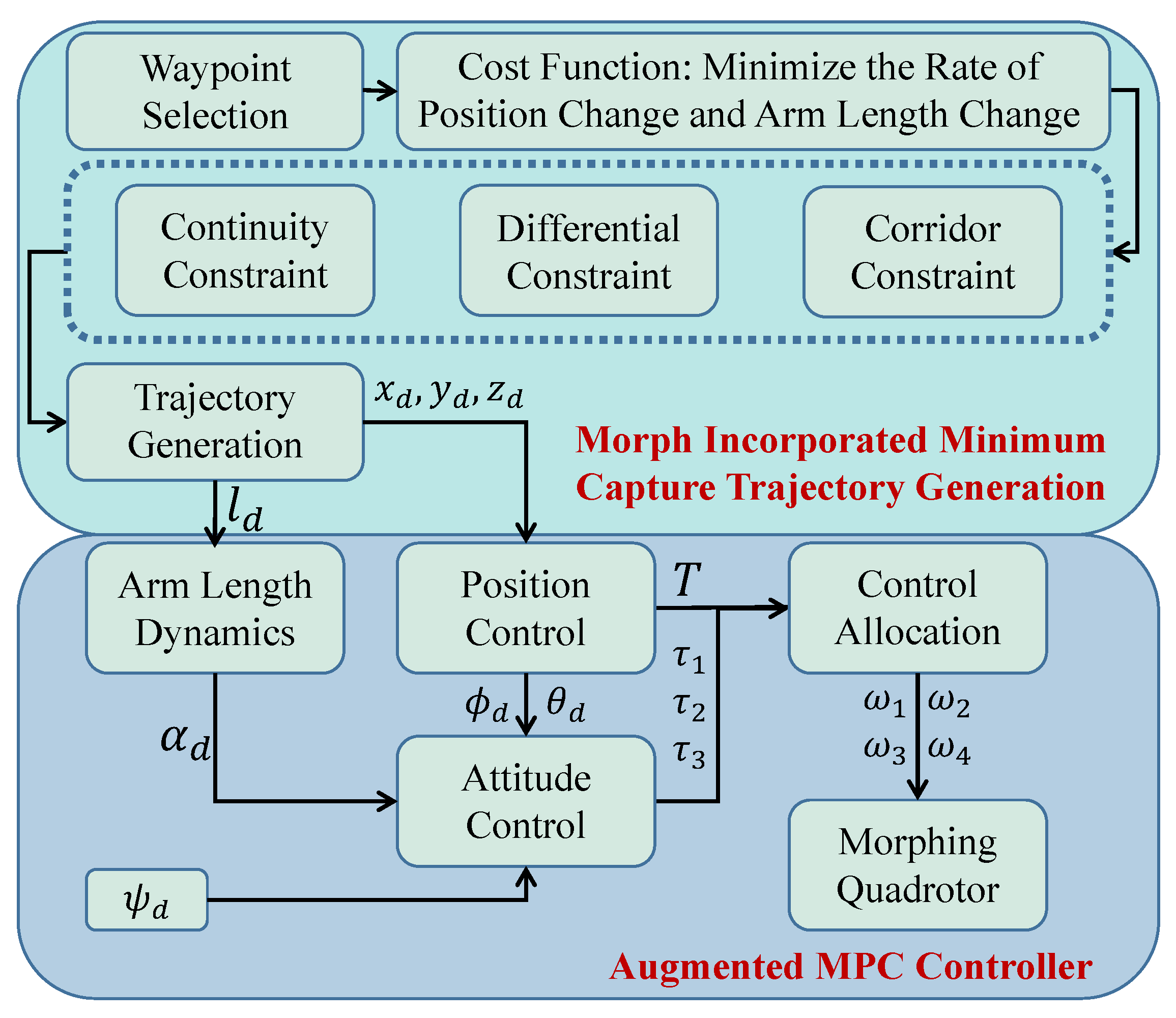
Figure 1. The structural framework of the layered optimization strategy and trajectory tracking control of the morphing quadrotor. The symbols will be followed up with in Section 2 and Section 3.
Drones 09 00304 g001
Figure 2. Illustration of the morphing quadrotor: (a) the coordinate system, and (b) a partially enlarged diagram of the arm.
Drones 09 00304 g002
Figure 3. Schematic diagram of the multiple constraints in minimum snap trajectory generation.
Drones 09 00304 g003
Figure 4. The results of the trajectory optimization: (a) a 3D trajectory graph, (b) a trajectory in the x y plane, and (c) a detailed diagram of the corridor. Different sizes of green ‘+’ represent different sizes of the morphing quadrotor.
Drones 09 00304 g004
Figure 5. The results of the generated position coordinates and the arm length: (a) position change p = [ x , y , z ] T , and (b) arm length change l.
Drones 09 00304 g005
Figure 6. The results of the augmented MPC-based position control: (a) the position tracking results, (b) control inputs with constraints, and (c) changing rates of the control inputs with constraints. The horizontal dashed lines in (b,c) indicate the constraint boundary, and parts of (b,c) are enlarged in detail. B–F: before filter, A–F: after filter. The same applies below.
Drones 09 00304 g006
Figure 7. The results of the augmented MPC-based attitude control: (a) attitude tracking results, (b) control inputs with constraints, and (c) changing rates of the control inputs with constraints.
Drones 09 00304 g007
Figure 8. The results of the augmented MPC-based position control in response to a step disturbance: (a) the position tracking results, (b) control inputs with constraints, and (c) the changing rates of the control inputs with constraints.
Drones 09 00304 g008
Figure 9. The results of the augmented MPC-based attitude control in response to a step disturbance: (a) the attitude tracking results, (b) control inputs with constraints, and (c) the changing rates of the control inputs with constraints.
Drones 09 00304 g009
Disclaimer/Publisher’s Note: The statements, opinions and data contained in all publications are solely those of the individual author(s) and contributor(s) and not of MDPI and/or the editor(s). MDPI and/or the editor(s) disclaim responsibility for any injury to people or property resulting from any ideas, methods, instructions or products referred to in the content.