Article

Estimation of Equivalent Transmitted Power of Sparse Array Based on Unmanned Aerial Vehicles in Collaborative Jamming

College of Intelligence Science and Technology, National University of Defense Technology, Changsha 410073, China
*
Author to whom correspondence should be addressed.
Drones 2025, 9(4), 242; https://doi.org/10.3390/drones9040242
Submission received: 13 February 2025 / Revised: 15 March 2025 / Accepted: 16 March 2025 / Published: 25 March 2025
(This article belongs to the Collection Drones for Security and Defense Applications)

Abstract

Unmanned Aerial Vehicles (UAVs) are widely used in defense applications. Multiple UAVs equipped with jamming sources can form a sparse array. The sparse array can be quickly deployed and achieve an extensive range of effective jamming. At present, the jamming power in the target area is mainly calculated through the superposition of node waveforms. The algorithm needs to sequentially calculate the angle of the target position relative to each node to obtain the corresponding gain and then calculate the path loss by the transmission model to obtain the total jamming power, which has high algorithmic complexity and needs to recount the power every time after adjusting the position of the node. An equivalent transmitted power estimation algorithm based on the pattern multiplication theorem is proposed in this paper, which regards the sparse array as a whole directional jammer. The power in the target area can be estimated according to the jammer gain, the equivalent transmitted power, and the jamming distance. In the calculation of jamming power, the proposed array-based algorithm reduces the complexity by 50% compared with the waveform superposition algorithm, and the estimation variance of the jamming power is less than 1.4%.

1. Introduction

Electronic warfare is an important form of modern warfare. Jammers interfere with communication systems by emitting electromagnetic waves, affecting the quality of communication and reducing combat effectiveness [1,2,3,4,5,6]. The increase in the dimensions of combat has put forward higher requirements for the coordination between equipment. This has made coordinated electronic jamming a development trend in electronic warfare. Coordination between jammers can extensively play to their respective advantages and minimize the impact of the shortcomings of individual jammers on the entire jamming system. Distributed beamforming has been widely used in coordinated jamming due to its high directivity and flexibility. This technology uses the coordination between array elements to optimize the main beam and half-power beamwidth and suppress sidelobes to achieve higher-quality power transmission [7,8,9]. These papers studied the impact of frequency and phase errors between nodes on beam efficiency. They used phase prediction models to estimate errors, track the drift of signals, and implement beam correction through probabilistic adaptive direction adjustment techniques. They proposed average received power and the amount of information exchange as evaluation indicators of the model’s overall performance. UAVs carry array elements due to their high mobility to achieve more efficient energy transmission [10]. Based on a nonlinear energy harvesting model, this paper proposed an energy efficiency maximization problem, which mainly involves the optimization of analog beamforming, trajectory planning, and transmission power control. The authors simplified the complex three-dimensional uniform linear array and designed a convex optimization iterative algorithm, which improved the convergence speed of the algorithm and achieved beam concentration. In addition to adjusting the positions of nodes to change the phase, directly adjusting the signal’s phase can gather more energy in the target area. The author proposed a phase adjustment algorithm in [11], similar to the Fresnel zone plate focusing principle. The far-field transmitter is constructively superimposed in the target area. Experiments have shown that the proposed method can produce a high-energy beam in the target area.
Under far-field conditions, distributed arrays form plane waves. However, the node spacing in coordinated jamming is usually greater than half a wavelength, which does not meet the far-field conditions. In such cases, sparse arrays have been proposed to solve this problem. The nodes in sparse arrays are composed of highly directional sub-arrays. These nodes aim at the target to implement precise jamming and can adjust the position and transmission power of the nodes according to the size of the area and the characteristics of the target. Under the limited transmission power of the nodes, by optimizing the beam of the sparse array, effective jamming can be achieved over a larger area [12,13,14]. These papers introduced matrix mapping to transform the strictly constrained optimization problem into a non-constrained problem with only upper and lower limits. Based on the genetic algorithm, the differential evolution of nodes is realized, and multiple beampattern matching is achieved by optimizing the positions of nodes and the phase of excitation current. The paper in [15] studied the configuration of arrays in regular and irregular networks, aiming to reduce the number of sub-arrays while maintaining the sensitivity of the system. Experiments have shown that the effective area of the same number of sub-arrays in regular networks is more significant than that in irregular networks. In [16], an asymmetric mapping method was proposed, which contrasts with traditional symmetric matrix mapping. Under the constraints of aperture, the number of sub-arrays, and the spacing of sub-arrays, the authors constructed two distinct mapping functions to optimize the array layout. This approach leads to performance improvements of 7.37% and 19.33% over the symmetric matrix mapping method, respectively. These papers used the pattern multiplication theorem to calculate the pattern of the sparse arrays, suppress the sidelobes, and improve the performance of the main beam but did not further calculate the transmission power of the sparse arrays and the power in the target area.
Some other research has studied the power optimization problem of sparse arrays in the target area. The primary approach is to obtain the total waveform by superimposing each node in the target area and then calculating the jamming power. The authors in [17] modified the transmission model, more accurately defined the protected area in precise jamming, proposed a new target optimization function, and simplified the complex covariance matrix into a semi-definite programming and mixed Boolean problem, which improved the jamming accuracy and power. The authors in [18] proposed three algorithms to reduce the grating lobe effect based on the Majorization–Minimization (MM) and Alternating Direction Method of Multipliers (ADMM) frameworks. Without relaxation algorithms, a proximal gradient method was designed to maintain the sparsity of the one-norm, achieving beam concentration. The authors in [19,20] proposed ADMM algorithms and Riemannian space optimization methods to solve non-convex and non-smooth problems under imperfect Channel State Information (CSI). The results showed that both the Signal to Interference Plus Noise Ratio (SINR) and the Combined Power Spectrum (CPS) were improved. However, these papers did not consider the array as a whole when calculating the received power. They needed to calculate the waveform after superposition in each grid sequentially. When the sub-array is a directional antenna, it is also necessary to estimate the angle between the target point and the sub-array to obtain the gain. This calculation method requires many resources and reduces the convergence speed of the algorithm.
Combining the contributions of the aforementioned literature, this paper proposes an equivalent transmitted power calculation method for sparse arrays. This algorithm treats the sparse array as a whole and calculates the pattern and gain. By combining the transmitted power of the sub-arrays, the transmitted power of the entire sparse array can be obtained. In the study of coordinated jamming, this method can more quickly calculate the power in the target area based on the array shape, thereby assessing the effectiveness of electronic warfare. The remainder of this paper is organized as follows: Section 2 describes the steps of the beam superposition algorithm for power calculation. Section 3 presents a universal method for calculating the array factor and sub-array pattern, eliminating the need to select different calculation models based on the array shape. Section 4 derives the calculation method for equivalent transmitted power. Section 5 calculates the estimation accuracy and compares the complexity with the beam superposition algorithm. Finally, Section 6 summarizes the entire paper.

2. The Waveform Superposition Algorithm

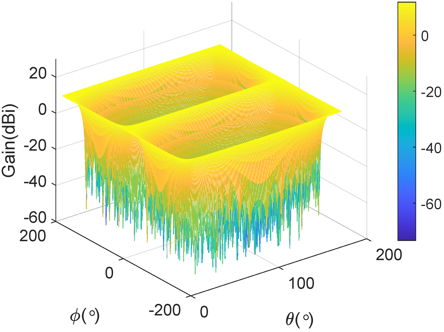
2.1. The Gain of Nodes

The diagram of collaborative jamming is shown in Figure 1. The jammers are formed by a uniform rectangular array. Each node aims at the target and sends a directional jamming beam, which is d k far from the target, and the steering vector of the beam is e j 2 π d k / λ . When the beams overlap, they form a high-power field within a specific range, jamming the communication receiver effectively. The jamming array is regarded as a whole, and the beam emitted by each node would form a directional combined beam towards the target under the far-field condition. In addition, redundant UAVs at the rear support the damaged UAVs to ensure a continuous jamming effect.
The normalized field pattern of node k is written as
f ( θ , ϕ ) = i = 1 n e j K ( u u 0 ) · x i
where K = 2 π / λ , u is the unit vector from the node’s element origin to the point ( L , θ , ϕ ) on the sphere, and x i is the vector of the node’s element pointing to the origin of the target. Thus, the gain of the node is expressed as
g ( θ , ϕ ) = 4 π η e | f ( θ , ϕ ) | 2 p t o t a l
where η e is the efficiency, and p t o t a l is the total radiated power of the node in the sphere, which is provided by
p t o t a l = 2 π 2 N e N a i = 1 N e 1 j = 1 N a 1 f ( θ i , ϕ j ) 2 sin θ i
where N e is the number of elevation grid points and N a is the number of azimuth grid points. The gain of the uniform linear array (ULA) is shown in Figure 2, which is composed of 16 isotropic antennas, assuming ϕ and θ of the target are 0 and π / 2 , respectively, and the space between the nodes is 0.5 λ . In the horizontal direction, the main lobe is concentrated at 0 and ± 180 . The symmetry in the gain pattern around these angles suggests that the array has a balanced radiation profile in the horizontal plane. The gain pattern exhibits uniform amplitude distribution in the vertical direction, implying that the ULA maintains consistent radiation characteristics across different elevation angles. The side lobes, visible at other angles, have significantly lower gain, indicating effective suppression of unwanted radiation in non-primary directions.
The gain of the uniform rectangular array (URA) is shown in Figure 3. Assume ϕ and θ of the target are 0 and π / 2 , respectively, and there are 4 main lobes of the array. This contrasts with the ULA, which typically exhibits fewer main lobes. The URA’s gain pattern shows that the energy is more concentrated in the main lobes, with significantly reduced side lobes compared to the ULA. This characteristic allows for more efficient focusing of jamming power towards the intended directions, thereby enhancing the effectiveness of the jamming signal. However, the presence of multiple main lobes means that only the lobe directed toward the target is useful for jamming. The power transmitted through the other main lobes is wasted and does not contribute to the jamming effort.

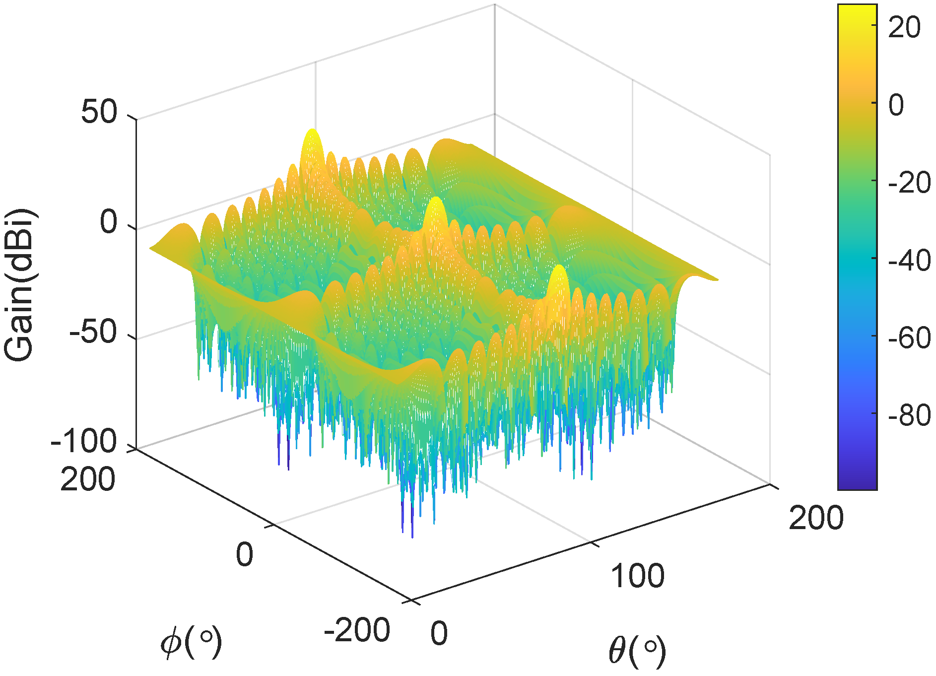
2.2. Waveform Superposition

Each node emits a directional jamming beam aimed at the target, as shown in Figure 4. These beams overlap at various positions in space, resulting in varying degrees of constructive and destructive interference. If these beams arrive at the target point simultaneously and are perfectly aligned in phase and frequency, the strongest interference effect can be achieved at the target location, maximizing the interference across the entire space.
The superposed waveform can be expressed as
x ( t ) = k = 1 N x k ( t )
where x k ( t ) is the waveform of node k:
x k ( t ) = A t k cos ( 2 π f c t + φ k 0 )
where A t k is the amplitude of the waveform, f c is the carrier frequency, and φ k 0 is the initial phase of the waveform, which is set according to the distance of the node from the target location L k 0 :
φ k 0 = K L k 0
where λ is the carrier wavelength. The amplitude relationship between the receiver and transmitter is
A r k ( θ , ϕ ) A t k = P r k ( θ , ϕ ) P t k
where P t k and P r k ( θ , ϕ ) are the transmitted and received power of the node, respectively.
According to the Friis formula, the received power is given by
P r k ( θ , ϕ ) = P t k · g ( θ k , ϕ k ) · G r ( θ , ϕ ) · λ 4 π L k ( θ , ϕ ) 2
where G r ( θ , ϕ ) is the gain of the target antenna, and L k ( θ , ϕ ) is the distance between the node and the point on the sphere. The θ k , ϕ k represents the azimuth and elevation angle of the point on the sphere concerning node k, respectively.
In order to calculate θ k , ϕ k , node k is regarded as the origin of the coordinates, and the z axis is the target’s direction. As shown in Figure 5, the coordinate is transformed. Assume P ( x , y , z ) is a point in the coordinate system. First, move the origin point to node k, whose coordinates are ( x k , y k , z k ) ; secondly, rotate ϕ counterclockwise with z as the axis, and then rotate θ counterclockwise with y as the axis.
The coordinate of P in the new coordinate system is given by
x y z = cos θ cos ϕ cos θ sin ϕ sin θ sin ϕ cos ϕ 0 sin θ cos ϕ sin θ sin ϕ cos θ x y z
Based on the new coordinate, the azimuth and elevation angle of the point on the sphere concerning node k are given by
θ k = arctan z x 2 + y 2 ϕ k = arctan 2 ( y , x )
Bring (8) to (7), and A r k ( θ , ϕ ) is written as
A r k ( θ , ϕ ) = A t k λ 4 π L k ( θ , ϕ ) · g ( θ k , ϕ k ) · G r ( θ , ϕ )
After the waveform is transmitted to the sphere, the phase is written as
φ k ( θ , ϕ ) = φ k 0 + K · L k ( θ , ϕ )
Therefore, the waveform after superposition of the point ( L , θ , ϕ ) on the sphere is given by
Y θ , ϕ ( t ) = k = 1 n A r k ( θ , ϕ ) · cos ( 2 π f c t + φ k ( θ , ϕ ) )
As a result, combined with (13), the jamming power is
P j , w a v e ( θ , ϕ ) = lim T 1 T T / 2 T / 2 Y θ , ϕ 2 ( t ) d t = lim T 1 T T / 2 T / 2 k = 1 N l = 1 N A r k ( θ , ϕ ) A r l ( θ , ϕ ) · cos 2 π f c t + φ k ( θ , ϕ ) · cos 2 π f c t + φ l ( θ , ϕ ) d t = 1 2 k = 1 N l = 1 N A r k ( θ , ϕ ) A r l ( θ , ϕ ) · cos φ k ( θ , ϕ ) φ l ( θ , ϕ ) = 1 2 k = 1 N l = 1 N A r k ( θ , ϕ ) A r l ( θ , ϕ ) [ cos ( φ k ( θ , ϕ ) ) cos ( φ l ( θ , ϕ ) ) + sin ( φ k ( θ , ϕ ) ) sin ( φ l ( θ , ϕ ) ) ]
bring (11) and (2) into (14),
P j , w a v e ( θ , ϕ ) = λ 2 8 π · p t o t a l k = 1 N l = 1 N A t k A t l L k ( θ , ϕ ) L l ( θ , ϕ )   · f ( θ k , ϕ k ) · G r ( θ , ϕ ) · f ( θ l , ϕ l ) · G r ( θ , ϕ )   · cos ( φ k ( θ , ϕ ) ) cos ( φ l ( θ , ϕ ) ) + sin ( φ k ( θ , ϕ ) ) sin ( φ l ( θ , ϕ ) )
Assume the target antenna is isotropic, so  G r ( θ , ϕ ) = 1 , and
A = [ A t 1 · f ( θ 1 , ϕ 1 ) cos ( φ 1 ( θ , ϕ ) ) L 1 ( θ , ϕ ) , A t n · f ( θ n , ϕ n ) cos ( φ n ( θ , ϕ ) ) L n ( θ , ϕ ) ] T B = [ A t 1 · f ( θ 1 , ϕ 1 ) sin ( φ 1 ( θ , ϕ ) ) L 1 ( θ , ϕ ) , , A t n · f ( θ n , ϕ n ) sin ( φ n ( θ , ϕ ) ) L n ( θ , ϕ ) ] T
Therefore, P j , w a v e ( θ , ϕ ) is given by
P j , w a v e ( θ , ϕ ) = η e λ 2 8 π · p t o t a l sum ( AA T ) + sum ( BB T )

3. Array-Based Jamming Power Estimation

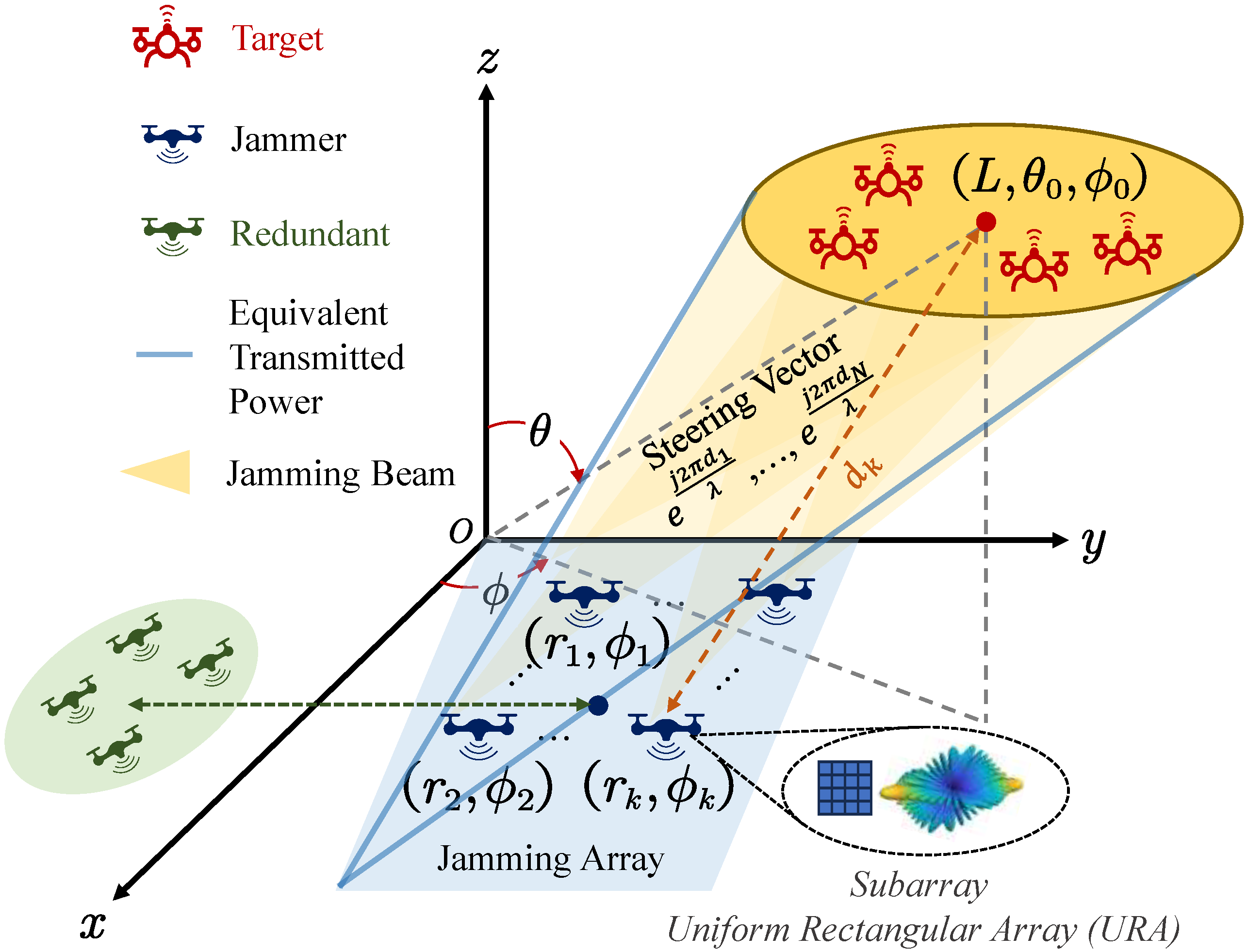
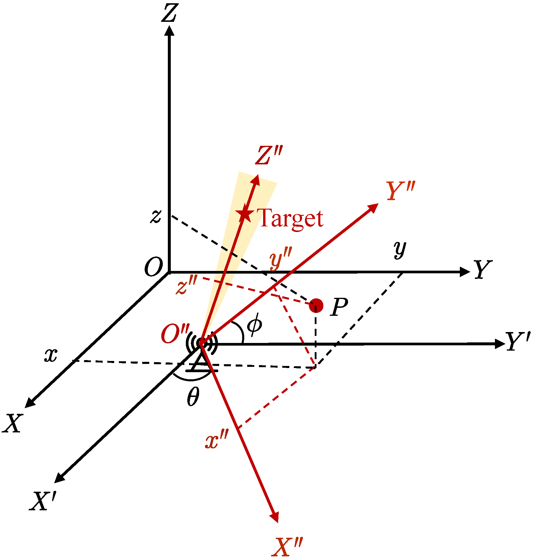
3.1. Sparse Array Model

Assume the jamming UAVs are randomly distributed in a circle with a radius of R. The array factor is written as
F a r r a y ( θ , ϕ ) = k = 1 N e j K ( d k ( θ , ϕ ) d k ( θ 0 , ϕ 0 ) )
where N is the number of nodes of the sparse array, and d k ( θ , ϕ ) is the distance between node k and the point ( L 1 , θ , ϕ ) on the far-field sphere:
d k 2 ( θ , ϕ ) = L 1 2 + r k 2 2 L 1 r k · sin θ sin θ k cos ( ϕ ϕ k ) + cos θ cos θ k
The 16 UAV nodes are distributed in the x o y plane, the distributed radius R is 5 m, the distance L 1 is 1000 m, and the carrier frequency is 400 MHz. The normalized array factor is shown in Figure 6, and the azimuth and elevation angles of the target are 0 and 60 , respectively. The amplitude of the main lobe is significantly higher than that of the side lobe. Compared with the uniform array, the random array shows a more focused distribution of the field pattern.
According to the pattern multiplication theorem, the beampattern of the sparse array is equal to the product of the node’s field pattern and the array factor:
B ( θ , ϕ ) = f ( θ , ϕ ) · F a r r a y ( θ , ϕ ) = i = 1 n e j K ( u u 0 ) · x i · k = 0 N 1 e j K ( d k d k 0 )
Therefore, the gain of the array is expressed as
G ( θ , ϕ ) = 4 π η a | B ( θ , ϕ ) | 2 P t o t a l
where η a and P t o t a l are the efficiency factor and total radiated power of the sparse array, respectively. P t o t a l is expressed as
P t o t a l = 2 π 2 N e N a i = 1 N e j = 1 N a B ( θ i , ϕ j ) 2 sin θ i

3.2. Equivalent Transmitted Power

The electromagnetic wave transmitted by the nodes continues to transmit L 2 forward to reach the target location; i.e., L = L 1 + L 2 . Assume the equivalent transmitted power of the array is P t , a r r a y , and the jamming power in the target area is given by
P j , a r r a y ( θ , ϕ ) = P t , a r r a y ( θ , ϕ ) · G ( θ , ϕ ) · λ 4 π L 2 2
According to the equation: P j , a r r a y ( θ , ϕ ) = P j , w a v e ( θ , ϕ ) , P t , a r r a y is given by
P t , a r r a y ( θ , ϕ ) = η e · 2 π L 2 2 sum ( AA T ) + sum ( BB T ) p t o t a l · G ( θ , ϕ ) = η e 2 η a · n 2 L 2 2 P t o t a l p t o t a l · sum ( AA T ) + sum ( BB T ) | B ( θ , ϕ ) | 2
Assume that the nodes consist of a 4 × 4 uniform rectangular array with 0.5 λ array element spacing; the sparse array consists of these nodes arranged randomly in a circle with a radius of 5 m. Assume A t k = 1 ,   θ = π / 2 ,   L 2 = 2500 ,   η e = η a = 1 , and the coordinate of the target in the Cartesian coordinate system is ( 0 , 5000 ) . The distribution curve of P t , a r r a y ( ϕ ) is shown in Figure 7, which is calculated according to (24), and the variance in the horizontal direction is 1.55 × 10 5 , showing that P t , a r r a y ( ϕ ) has little difference at all angles.
Take the equivalent transmitted power at the target orientation ϕ 0 as the equivalent transmitted power of the array; i.e., P t , a r r a y ( ϕ ) = P t , a r r a y ( ϕ 0 ) . Furthermore, since the nodes’ beams are aligned to the target, so f ( ϕ 0 ) = 1 , the beampattern at the target orientation B ( ϕ 0 ) is equal to N, and P t , a r r a y is written as
P t , a r r a y = L 2 2 2 · n N · P t o t a l p t o t a l 2 · [ sum ( AA T ) + sum ( BB T ) ]
As shown in (25), P t , a r r a y of the array is only related to the nodes themselves and the distribution of the array. Moreover, there is no need to calculate the relative positions between the nodes and the target, reducing the computational complexity.

4. Discussion

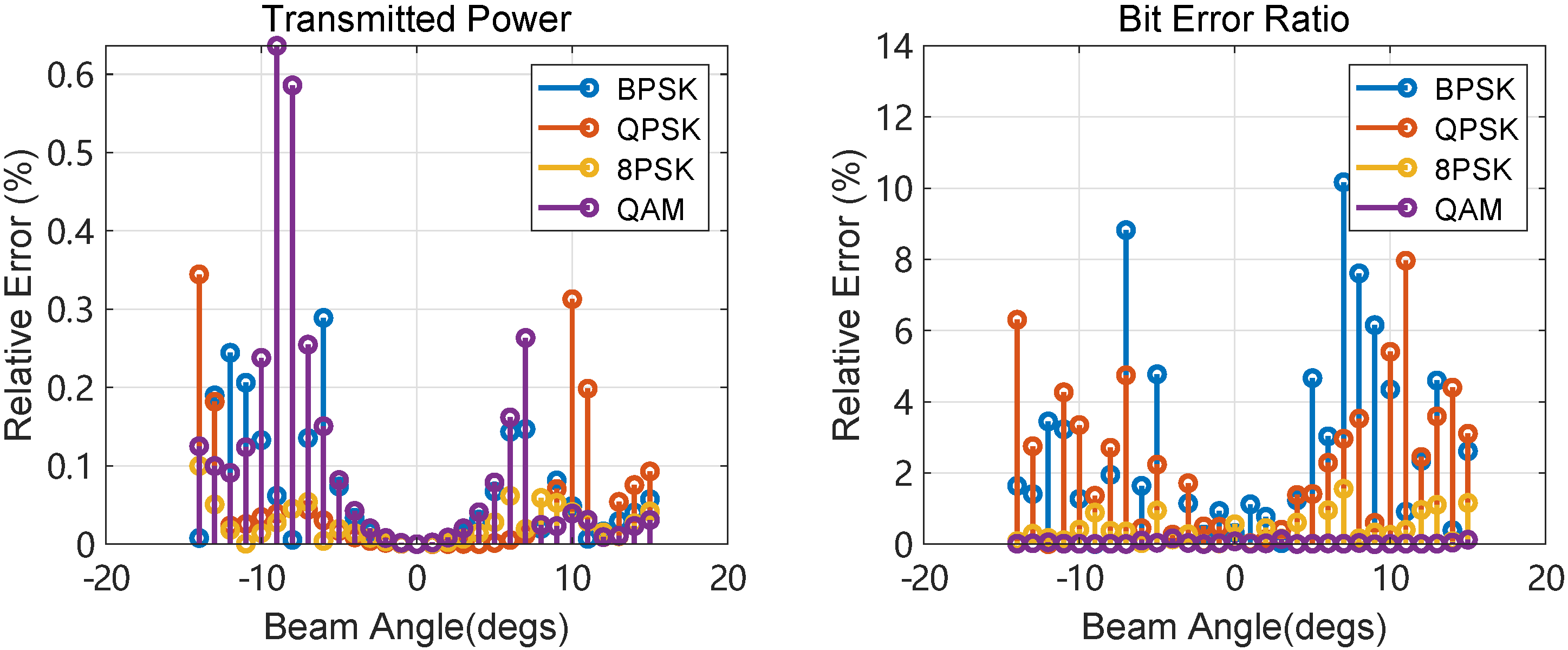
4.1. Accuracy of Jamming Power Estimation

In order to verify the rationality of P t , a r r a y , the jamming power results are compared between (23) and (17). The carrier frequency is 400   MHz , the number of nodes is 16, which are distributed in the x o y plane, and the array radius is 5 m. The distribution of the jamming power is shown in Figure 8. The wave-superposition method could be regarded as the true value of the jamming power; the curves of the two algorithms are basically the same, and the estimated jamming power at every azimuth angle is almost equal to the true value.
In order to further evaluate the accuracy of the estimation, the relative errors between the two algorithms are shown in Figure 9. The relative errors are all less than 1.4%, showing good accuracy of the proposed method. As a result, the jamming power evaluation could be simplified using the array-based algorithm.

4.2. Algorithm Complexity Analysis

The waveform superposition algorithm calculates the jamming power based on (1), (16), and (17). The computational complexity of the normalized field pattern is O ( n ) , and the computational complexity of calculating θ , ϕ in (16) is O ( n ) . Equation (17) contains two summations with a computational complexity of O ( n 2 ) , so the waveform superposition algorithm has a complexity of O ( n 2 ) . Similar to the waveform superposition algorithm, the array-based algorithm relies on (16), (23), and (25), which has a complexity of O ( n 2 ) . However, since the angle of each point on the sphere concerning the node needs to be iterated in the waveform superposition algorithm, the running time is increased. The array-based algorithm in this paper only needs to focus on the transmitted power and distribution of the nodes, reducing the computational complexity.
Under the same conditions, the running times of the two algorithms are compared. The results are shown in Figure 10. With the increase in the number of nodes, the calculation complexity of ( θ , ϕ ) increases, so the running time of the waveform superposition algorithm increases significantly. In contrast, the running time of the array-based algorithm is maintained within 1 s, basically unaffected by the number of nodes, which can shorten the response time of the jammer and improve the response speed of electronic warfare in practical applications.

5. Experiment

5.1. Jamming Evaluation

In order to verify the accuracy of the jamming power estimation, several experiments are conducted with different modulation types. Sixteen UAVs are located in a circle with a radius of 5 m, the jamming power of each UAV is 50 mW, and the transmitted power of each target is 1 W. The center of the UAVs is 1000 m far from the target, while the distance within the target is 200 m. Assume the jamming beam’s width is 30 , and the target is within the beam. The bit error ratios (BERs) of different modulation types are shown in Figure 11. An improvement in BER indicates that the jamming impacts the signal quality, especially the complex modulation format, which shows a higher BER in different directions. In addition, the two jamming transmitted power estimation methods show good consistency, proving that the proposed method is applicable to different communication systems.
Furthermore, constellation diagrams are obtained from the demodulated signals. Figure 12a illustrates the constellation diagram of the target receiver under ideal conditions without jamming, where the signals are uniformly distributed across different quadrants, demonstrating high communication quality. However, as jamming is introduced, as shown in Figure 12b, it becomes challenging to recover the original signals as they overlap and cannot be effectively separated. This further validates the significant impact of jamming signals on the communication system.
The relative errors of the transmitted power and BER are calculated to validate the proposed transmitted power estimation method’s accuracy further. As shown in Figure 13, the results across all modulation formats demonstrate the high precision of the estimation method. Due to the uncertainty of the channel and the small BER, the relative error of BER is slightly larger than that of the transmitted power. The accuracy is higher in the high-order modulation than in the low-order modulation, which is expected due to the higher complexity of the high-order modulation.

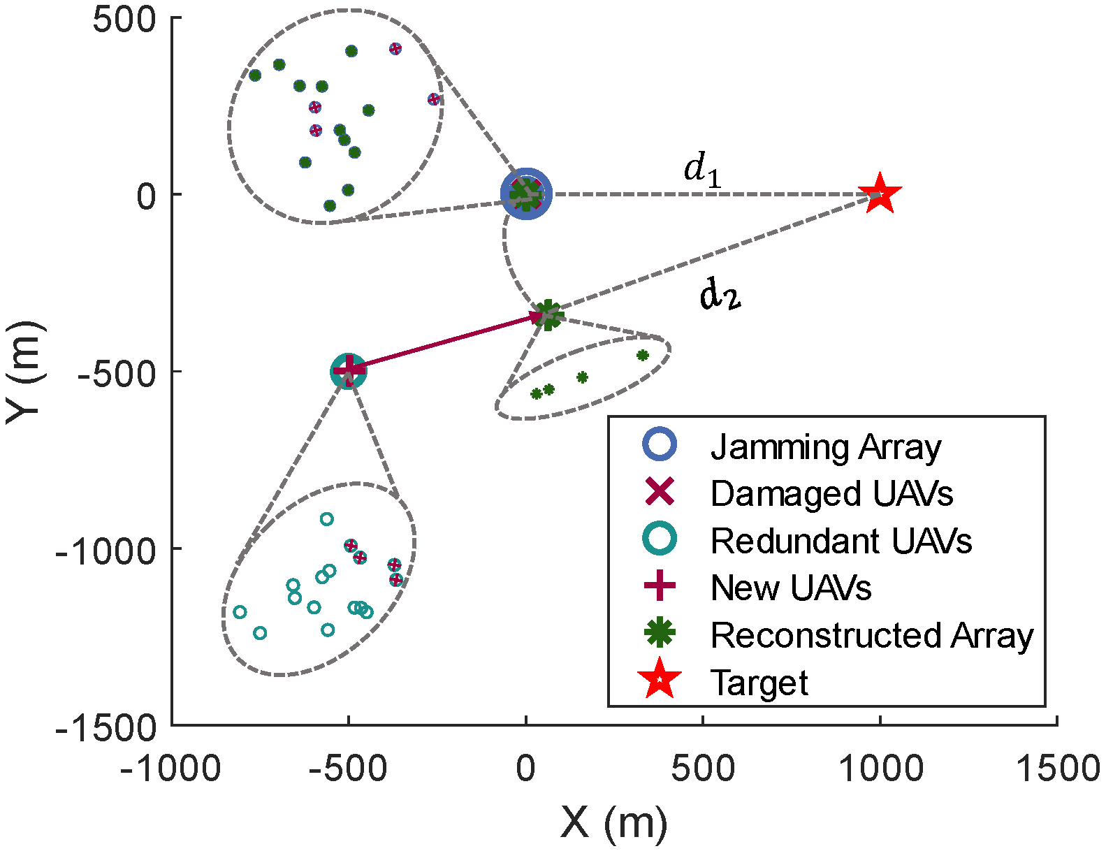
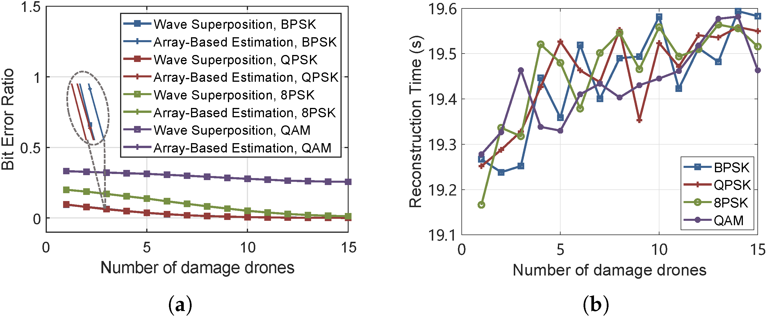
5.2. Jamming Array Reconstruction After Attack

When UAVs conduct jamming, they are also susceptible to attacks. Therefore, it is essential to deploy redundant UAVs in the rear. This paper investigates scenarios where UAVs are attacked, the selection of new UAVs to join the jamming array, and the time required to restore jamming. It is assumed that there are also 16 redundant UAVs located 500 m from the jamming array. When the jamming array is attacked, the nearest redundant UAV is selected to join the array. The positions of the UAVs and the target are shown in the figure. When UAVs in the jamming array are attacked, the nearest redundant UAV is selected to reconstruct the jamming array. Notably, the new UAV does not need to fly to the position of the damaged UAV but instead chooses a location that is equidistant from the target as the damaged UAV. In Figure 14, distances d 1 and d 2 are the same, so the new UAV selects a closer position, thereby saving time.
The relationship between the number of damaged UAVs and the bit error rate (BER) is simulated. As shown in Figure 15a, when the attack intensifies, the jamming effectiveness gradually decreases, and the trends for BPSK and QPSK are almost identical. Figure 15b illustrates the time required for jamming array reconstruction. Assuming a UAV flight speed of 30 m/s, the more UAVs that are reinforced, the more complex the mission decision-making and trajectory planning become, resulting in longer time consumption. In addition, the BER after the reconstruction is higher than that before the reconstruction. As shown in Table 1, the effective jamming is re-implemented after 4 UAVs are damaged, and the BER returns to normal.

6. Conclusions

Sparse arrays composed of UAVs have much larger spacing than half-wavelength. However, they can configure the sub-arrays more flexibly for more efficient power transfer and more extensive coverage, and collaborative jamming in defense applications takes advantage of this to improve maneuverability. When calculating the power distribution in the target region, the waveform superposition algorithm must calculate the jamming waveforms at all the sphere points, then superpose them and integrate them to calculate the jamming power, which is a complicated calculation and reduces the computational efficiency. Therefore, this paper takes the sparse array as a whole, the total equivalent transmitted power is calculated, and the jamming power is estimated based on the array gain and the transmission model. The proposed algorithm dramatically reduces the computational complexity and improves the defense efficiency.

Author Contributions

All authors contributed significantly to the research and development of this manuscript. Y.Z.: Conceptualization, methodology, software, data curation, writing—original draft, visualization. Z.Z.: Supervision, project Administration. Z.H.: Software, data curation, validation. J.Z.: Formal analysis, resources, data curation. J.B.: Writing—review and editing, funding acquisition. L.L.: Formal analysis, investigation. H.H.: Visualization and validation. All authors have read and agreed to the published version of the manuscript.

Funding

This research was funded by the National Natural Science Youth Foundation of China under Grant No. 62201598.

Data Availability Statement

The data presented in this study are available upon request from the corresponding author.

DURC Statement

The current research is limited to UAVs’ electromagnetic countermeasures, which is beneficial to the development of low-altitude defense in collaborative jamming and does not pose a threat to public health or national security. The authors acknowledge the dual-use potential of research involving UAVs equipped with jamming nodes and confirm that all necessary precautions have been taken to prevent potential misuse. As an ethical responsibility, the authors strictly adhere to relevant national and international laws about DURC. The authors advocate for responsible deployment, ethical considerations, regulatory compliance, and transparent reporting to mitigate misuse risks and foster beneficial outcomes.

Conflicts of Interest

The authors declare that they have no known competing financial interests or personal relationships that could have appeared to influence the work reported in this paper.

References

  1. Spezio, A. Electronic warfare systems. IEEE Trans. Microw. Theory Tech. 2002, 50, 633–644. [Google Scholar] [CrossRef]
  2. Kim, D.G.; Park, G.H.; Kim, H.N.; Park, J.O.; Park, Y.M.; Shin, W.H. Computationally Efficient TDOA/FDOA Estimation for Unknown Communication Signals in Electronic Warfare Systems. IEEE Trans. Aerosp. Electron. Syst. 2018, 54, 77–89. [Google Scholar] [CrossRef]
  3. Gupta, M.K.; Hareesh, G.; Mahla, A. Electronic Warfare: Issues and Challenges for Emitter Classification. Def. Sci. J. 2011, 61, 228–234. [Google Scholar] [CrossRef]
  4. Sharma, P.; Sarma, K.K.; Mastorakis, N.E. Artificial Intelligence Aided Electronic Warfare Systems- Recent Trends and Evolving Applications. IEEE Access 2020, 8, 224761–224780. [Google Scholar] [CrossRef]
  5. You, S.; Diao, M.; Gao, L. Deep Reinforcement Learning for Target Searching in Cognitive Electronic Warfare. IEEE Access 2019, 7, 37432–37447. [Google Scholar] [CrossRef]
  6. Zhang, C.; Wang, L.; Jiang, R.; Hu, J.; Xu, S. Radar Jamming Decision-Making in Cognitive Electronic Warfare: A Review. IEEE Sens. J. 2023, 23, 11383–11403. [Google Scholar] [CrossRef]
  7. Mittal, A.; Xu, Z.; Du, K.; Kumar, S.S.; Shrivastava, A. An Ultralow-Power Closed-Loop Distributed Beamforming Technique for Efficient Wireless Power Transfer. IEEE Internet Things J. 2024, 11, 31301–31316. [Google Scholar] [CrossRef]
  8. Sharma, S.; De, S. Distributed RF Beamforming for Wireless Power Transfer Over Time Varying Channels. In Proceedings of the ICC 2023—IEEE International Conference on Communications, Rome, Italy, 28 May–June 2023; pp. 919–924. [Google Scholar] [CrossRef]
  9. Guo, W.; Wang, Z.; Zhou, H.; Zhou, W.; Cui, X.; Zhang, J. DPDA: Distributed Probability-adaptive Direction Adjustment for Magnetic Wireless Power Transfer. In Proceedings of the 2023 20th Annual IEEE International Conference on Sensing, Communication, and Networking (SECON), Madrid, Spain, 11–14 September 2023; pp. 142–150. [Google Scholar] [CrossRef]
  10. Yuan, X.; Jiang, H.; Hu, Y.; Schmeink, A. Joint Analog Beamforming and Trajectory Planning for Energy-Efficient UAV-Enabled Nonlinear Wireless Power Transfer. IEEE J. Sel. Areas Commun. 2022, 40, 2914–2929. [Google Scholar] [CrossRef]
  11. Fan, X.; Ding, H.; Zhang, Y.; Trappe, W.; Han, Z.; Howard, R. Distributed beamforming based wireless power transfer: Analysis and realization. Tsinghua Sci. Technol. 2020, 25, 758–775. [Google Scholar] [CrossRef]
  12. Liu, H.; Zhao, H.; Li, W.; Liu, B. Synthesis of Sparse Planar Arrays Using Matrix Mapping and Differential Evolution. IEEE Antennas Wirel. Propag. Lett. 2016, 15, 1905–1908. [Google Scholar] [CrossRef]
  13. Gu, P.; He, Z.; Xu, J.; Leung, K.W.; Chen, R.S. Design of Wide Scanning Sparse Planar Array Using Both Matrix-Pencil and Space-Mapping Methods. IEEE Antennas Wirel. Propag. Lett. 2021, 20, 140–144. [Google Scholar] [CrossRef]
  14. Yepes, L.F.; Covarrubias, D.H.; Alonso, M.A.; Ferrús, R. Hybrid Sparse Linear Array Synthesis Applied to Phased Antenna Arrays. IEEE Antennas Wirel. Propag. Lett. 2014, 13, 185–188. [Google Scholar] [CrossRef]
  15. Syeda, R.Z.; de Vaate, J.G.b.; Prinsloo, D. Regular and Irregular-on-Grid Sparse Array Comparison of Connected Aperture Arrays. IEEE Antennas Wirel. Propag. Lett. 2020, 19, 586–590. [Google Scholar] [CrossRef]
  16. Dai, D.; Yao, M.; Ma, H.; Jin, W.; Zhang, F. An Asymmetric Mapping Method for the Synthesis of Sparse Planar Arrays. IEEE Antennas Wirel. Propag. Lett. 2018, 17, 70–73. [Google Scholar] [CrossRef]
  17. Song, D.; Wang, W.; Xu, Z.; Xiong, Z.; Kirubarajan, T. Focused energy delivery with protection for precision electronic warfare. IEEE Trans. Aerosp. Electron. Syst. 2016, 52, 3053–3064. [Google Scholar] [CrossRef]
  18. Chen, S.; Xu, C.; Zhang, J. Efficient focused energy delivery with grating lobe mitigation for precision electronic warfare. Signal Process. 2020, 169, 107409. [Google Scholar] [CrossRef]
  19. Yang, Z.; Li, Z.; Yu, X.; Zhou, Q.; Huang, C.; Zhang, J. Maximin Design of Wideband Constant Modulus Waveform for Distributed Precision Jamming. IEEE Trans. Signal Process. 2024, 72, 1316–1332. [Google Scholar] [CrossRef]
  20. Huang, C.; Huang, Z.; Zhou, Q.; Li, Z.; Yang, Z.; Zhang, J. Joint Transmit Waveform and Receive Filter Design for the DFRC System With Imperfect CSI. IEEE Trans. Radar Syst. 2024, 2, 288–302. [Google Scholar] [CrossRef]
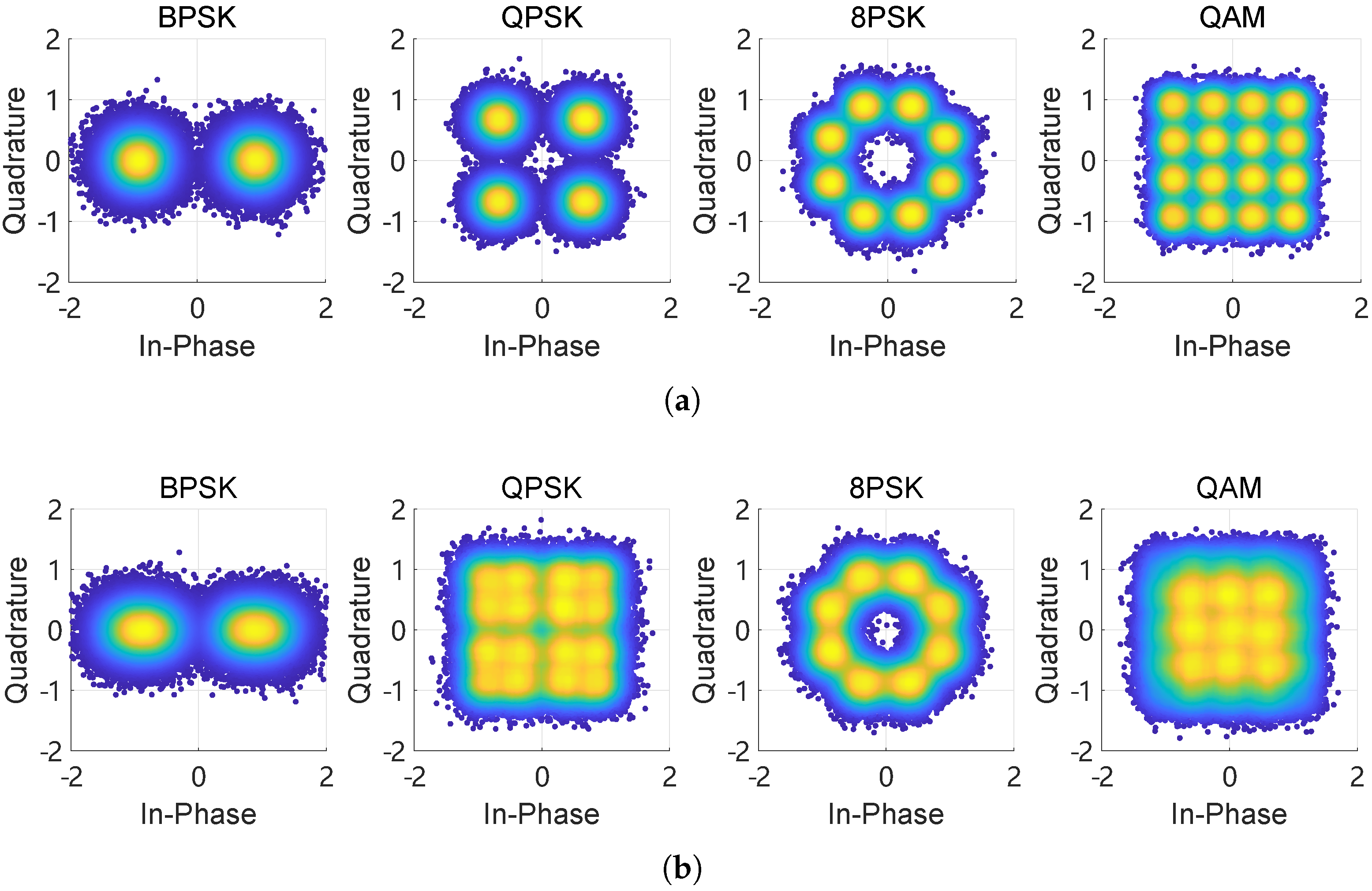
Figure 1. The diagram of collaborative jamming. The jammers are distributed in the x o y plane, the coordinate of jammer k is ( r k , ϕ k ), and the target is located at ( L , θ 0 , ϕ 0 ) .
Drones 09 00242 g001
Figure 2. The gain of ULA.
Drones 09 00242 g002
Figure 3. The gain of URA.
Drones 09 00242 g003
Figure 4. The diagram of wave superposition.
Drones 09 00242 g004
Figure 5. The diagram of coordinate system transformation: the coordinates change from ( x , y , z ) to ( x , y , z ) .
Drones 09 00242 g005
Figure 6. The array factor of a sparse array.
Drones 09 00242 g006
Figure 7. Equivalent transmitted power distribution in the horizontal direction.
Drones 09 00242 g007
Figure 8. Jamming power comparison between the array-based algorithm and the waveform superposition algorithm.
Drones 09 00242 g008
Figure 9. The relative errors between the array-based algorithm and the waveform superposition algorithm.
Drones 09 00242 g009
Figure 10. Running time comparison between the array-based algorithm and the waveform superposition algorithm.
Drones 09 00242 g010
Figure 11. The BERs of different modulation types, and the carrier frequency is 400 MHz.
Drones 09 00242 g011
Figure 12. The constellation diagrams of the target receiver under different conditions. (a) The constellation diagram of the target receiver under ideal conditions. (b) The constellation diagram of the target receiver under jamming conditions.
Drones 09 00242 g012
Figure 13. The relative errors between the array-based estimation algorithm and the waveform superposition algorithm under different modulation types.
Drones 09 00242 g013
Figure 14. The positions of the UAVs and the target. The selected redundant UAVs fly to the given position to join the jamming task, and the unattacked UAVs continue to maintain the formation.
Drones 09 00242 g014
Figure 15. The impact of UAV attack and the time required to reconstruct the jamming array. (a) The bit error rate versus the number of damaged UAVs. (b) The reconstruction time versus the number of damaged UAVs.
Drones 09 00242 g015
Table 1. The bit error ratio after the jamming array reconstruction.
Modulation TypeBPSKQPSK8PSKQAM
BER10.11580.11620.21820.3360
BER20.11600.11700.21890.3364
Note: BER1 is the result based on the wave superpositon algorithm, and BER2 is the result based on the array-based estimation algorithm.
Disclaimer/Publisher’s Note: The statements, opinions and data contained in all publications are solely those of the individual author(s) and contributor(s) and not of MDPI and/or the editor(s). MDPI and/or the editor(s) disclaim responsibility for any injury to people or property resulting from any ideas, methods, instructions or products referred to in the content.

