Article

OTFS-Based Handover Triggering in UAV Networks

by
Ehab Mahmoud Mohamed
1,
Hany S. Hussein
2,3,
Mohammad Ahmed Alnakhli
1 and
Sherief Hashima
4,5,*
1
Department of Electrical Engineering, College of Engineering in Wadi Addawasir, Prince Sattam Bin Abdulaziz University, Wadi Addawasir 11991, Saudi Arabia
2
Electrical Engineering Department, College of Engineering, King Khaled University, Abha 62529, Saudi Arabia
3
Electrical Engineering Department, Aswan Faculty of Engineering, Aswan University, Aswan 81452, Egypt
4
Computational Learning Theory Team, RIKEN-Advanced Intelligence Project, Fukuoka 819-0395, Japan
5
Engineering Department, Nuclear Research Center, Egyptian Atomic Energy Authority, Cairo 13759, Egypt
*
Author to whom correspondence should be addressed.
Drones 2025, 9(3), 185; https://doi.org/10.3390/drones9030185
Submission received: 14 January 2025 / Revised: 25 February 2025 / Accepted: 27 February 2025 / Published: 3 March 2025

Abstract

:
In this paper, delay Doppler (DD) domain is utilized for enabling an efficient handover-triggering mechanism in highly dynamic unmanned aerial vehicles (UAVs) or drones to ground networks. In the proposed scheme, the estimated DD channel gains using DD multi-carrier modulation (DDMC), e.g., orthogonal time frequency space (OTFS) modulation, are utilized for triggering the handover decisions. This is motivated by the fact that the estimated DD channel gain is time-invariant throughout the whole OTFS symbol despite the entity speed. This results in more stable handover decisions over that based on the time-varying received-signal strength (RSS) or frequency time (FT) channel gains using orthogonal frequency division multiplexing (OFDM) modulation employed in fifth-generation–new radio (5G-NR) and its predecessors. To mathematically bind the performance of the proposed scheme, we studied its performance under channel estimation errors of the most dominant DD channel estimators, i.e., least square (LS) and minimum mean square error (MMSE), and we prove that they have marginal effects on its performance. Numerical analyses demonstrated the superiority of the proposed DD-based handover-triggering scheme over candidate benchmarks in terms of the handover overhead, the achievable throughput, and ping-pong ratio under different simulation conditions.

1. Introduction

Recently, many research efforts have been performed in the integration of the air segment, containing aerials such as fixed-wing aircrafts, unmanned aerial vehicles (UAVs), or drones, with the ground segment, containing mobile base stations (BSs) and user equipment (UE) [1,2], especially in space–air–ground integrated networks (SAGINs) [3]. The UAVs’ ability to fly, hover, and maneuver enable them to be utilized in a wide range of wireless communication applications [4,5,6,7]. They can be used in rescue operations after natural disasters, where they can quickly establish temporary communication networks for successful relief services [4]. Also, they can be used for providing wireless connectivity like flying BSs or relays for connecting users in remote and rural areas as well as in advanced technologies like metaverse [5]. By utilizing reconfigurable intelligent surface (RIS), UAV-mounted RIS can strengthen the coverage in crowdy hotspots [6]. Furthermore, collecting data from the internet of things (IoT) devices can be easily performed using flying UAVs [7].
Although the integration of UAVs with ground networks has a significant impact on future communications, mobility management poses a significant challenge due to the high speeds of the UAVs or ground entities like highspeed trains (HSTs). These speeds vary, ranging from 5 Km/Hr for UAVs to over 1000 Km/Hr for fixed-wing aircrafts or HSTs. This high speed introduces a substantial Doppler shift in the communication channel, rendering it exceedingly time varying [8]. This results in highly time-varying channels between UAVs and ground entities in the time domain. In both pre-planned aircraft routes and spontaneous UAV trajectories, it is crucial to seamlessly transfer the UAV connection from one ground BS (GBS) to another to maintain un-interrupted connectivity. Likewise, when UAVs function as airborne BS (ABS), smooth handovers of ground entities, e.g., HST, should occur between different coverage ABSs while they are in motion [9]. The current technology of using received signal strength (RSS)-based handover triggering or the estimated channel gains in frequency time (FT) domain using OFDM modulation will be inefficient in these scenarios [10]. This is because, in RSS, the handover decision is taken based on comparing the received powers in the time domain from the serving and the target cells, which are highly fluctuated. Also, the FT channel suffers from this time dependency due to the inter-carrier interference (ICI) coming from the high Doppler shifts. This results in highly increasing the handover overheads and decreasing the achievable throughput in consequence. Moreover, unnecessary handovers occur, which increases the ping-pong ratio. Sometimes, when the handover rate is ultimately high, the communication links between UAVs and ground entities cannot be efficiently established, which ends up with frequent communication failures [11]. Thus, designing a stable handover triggering mechanism is of the most importance in this highly time-varying environment.
In this paper, an efficient handover-triggering scheme is proposed based on the delay Doppler (DD) representation of the channel [12,13,14,15]. In this context, DD multi-carrier (DDMC), like orthogonal time frequency space modulation (OTFS), can be used for estimating the DD channel to trigger the handover decisions. OTFS is a new modulation scheme presented in 2017 by Hadani as an alternative to the conventional OFDM modulation [12]. The main idea of OTFS is to combat the ICI occurring in OFDM due to high Doppler shifts [13]. This can be accomplished by spreading the transmitted symbols over the whole channel in the DD domain instead of the FT domain used in OFDM. This approach allows OTFS to maintain orthogonality across both time and frequency axes simultaneously, resulting in superior resilience to time-varying channels and Doppler shifts [12,13]. By transforming the signal into a 2D representation, OTFS ensures that symbols remain well separated in the presence of high mobility or multipath propagation, thereby mitigating ICI in addition to inter-symbol interference (ISI). Thus, in OTFS, the DD channel gain becomes constant over the whole OTFS symbol duration regardless of the Doppler frequency shift coming from different velocities of the transmitter (Tx), receiver (Rx), or surrounding reflectors. Since its invention, a lot of research efforts have been made to deeply understand and investigate the operation of OTFS, including the design of efficient OTFS equalizers and channel estimators [14,15]. Also, it was applied in various communication systems as given in [16,17]. In this paper, leveraging the estimated DD channel using OTFS modulation, we suggest initiating handovers between UAV and ground entities based on it rather than relying on the time-varying RSS or FT channel gains. Although we used OTFS in this paper, other DDMC alternatives like orthogonal delay Doppler modulation (ODDM) [18] or orthogonal delay scale space (ODSS) modulation [19] can be applied to the proposed scheme without any necessary modifications. Thus, the main contributions of this paper can be summarized as follows:
  • We will investigate the issue of handover triggering within an integrated UAV-to-ground network, employing the time-varying DD channel modeling given in [8]. Subsequently, we will demonstrate that both the conventional RSS and the FT channel gain-based handover triggering are significantly time-variant, particularly in this highly dynamic environment characterized by extreme UAV velocities.
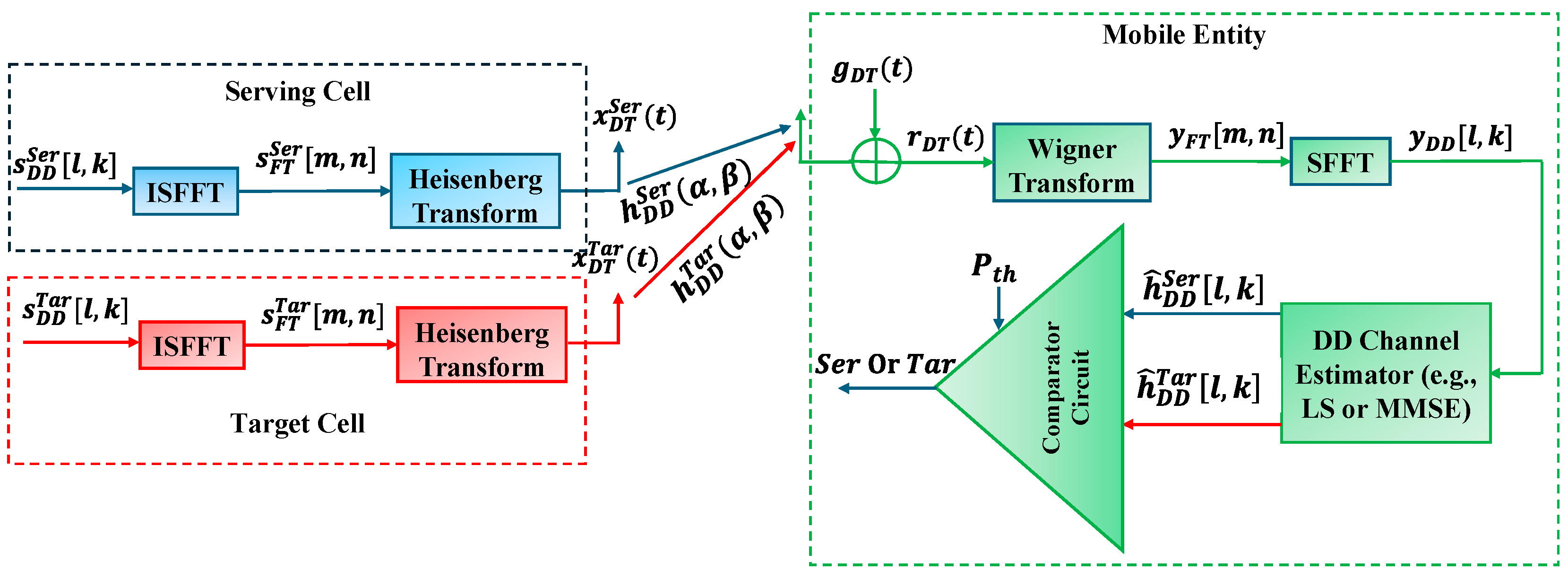
  • We will propose a handover-triggering framework based on OTFS modulation, where the estimated DD channel will be used for initiating the handover routines. In this scenario, the DD channel gains from the serving and target cells are compared, upon which a handover decision will be made. In this paper, we will mathematically prove that the DD channel power is constant over the whole OTFS symbol duration even in time-varying DD channel conditions. Through this stable handover-triggering strategy, a low number of handover decisions are made, and high throughput will be achieved coming from the lower handover-signaling overhead and the lower unnecessary handovers.
  • As the proposed approach relies on the estimated DD channel, it is vulnerable to channel estimation errors. To bind this effect on the performance of the proposed scheme, we mathematically study the channel estimation errors in the most dominant DD channel estimation strategies, which are least square (LS)- and minimum mean square error (MMSE)-based channel estimators. In both cases, we showed that the variance of the channel estimation error is lower than that introduced by additive white Gaussian noise (AWGN) at Rx, which proves the efficiency of the proposed scheme even under channel estimation errors.
  • Numerical analyses are conducted to prove the potency of the proposed DD handover strategy over the conventional RSS and FT channel gain-based ones in terms of the handover overhead, the achievable throughput, and the ping-pong ratio in different scenarios. Also, the performance of the proposed scheme under the effect of channel estimation error is bounded using numerical simulations.
The reminder of this paper is structured as follows: Section 2 gives the works related to that presented in this paper. Section 3 presents the UAV-to-ground handover scenarios and channel modeling. Section 4 explores the OTFS modulation, including its mathematical foundation. Section 5 gives the proposed DD channel-based handover triggering. Section 6 gives the mathematical analysis of the channel estimation error effect on the performance of the proposed scheme. Section 7 gives the conducted numerical analysis followed by the concluding remarks in Section 8.
The definitions of mathematical symbols used in this paper are given in Table 1.

2. Related Works

Several research studies have investigated the integration of UAV systems with ground networks, recognizing their unique flight capabilities within the broader framework of SAGIN [4,5,6,7]. In [4], a UAV is used for post-disaster rescue operations, where online learning was utilized to optimize its trajectory for maximizing the total system rate while considering the limited battery budget of both UAV and victims. In [5], the authors explored how UAVs serving as ABSs can enhance content delivery for metaverse users, focusing on factors like delivery success probability and average delay. It proposed a novel ABS association strategy based on received power and cache hit probability, highlighting optimal UAV deployment parameters for improved content delivery in the metaverse. In [6], UAV mounted RIS was used to strengthen the coverage in crowdy hotspots, such as stadiums or train stations. In this regard, the authors proposed an online learning approach to optimize the UAV trajectory over these hotspots without any prior information about them or their traffic needs. In [7], a laser-powered UAV-based data collection scheme for IoT networks was proposed to enhance energy efficiency, introducing an improved clustering algorithm and a novel approach for determining optimal visiting order and entry points for IoT device clusters.
Regarding UAV-to-ground handovers, the primary focus of this paper, there exists some research efforts exploring this issue, as given in [9,20,21,22,23]. In [9], a path-loss-plus-fading model for handover in UAV networks was proposed, where a discrete time Markov chain using Nakagami-m distribution was utilized to analyze the handover-triggering probability. However, this study relies on the traditional RSS-based handover-triggering method. In [20], deep reinforcement learning (DRL) was used to enhance connectivity for UAVs within cellular networks by improving the handover routines. Yet, RSS is still used for handover triggering. In [21], the software-defined networking (SDN) platform was enhanced by using UAVs as on-demand forwarding switches. The aim was to reduce handover latency and improve the handover performance of SDN using UAVs, but still RSS was the main enabler for handover triggering. In [22], the impact of different altitudes of UAVs on handover performance was investigated via addressing a gap in understanding 3D placement effects. Through modeling and analysis, the study establishes equivalence in handover occurrence processes across mobility scenarios and derives computationally efficient upper bounds for handover rates, demonstrating their accuracy through numerical examples. However, RSS was used as the metric for handover triggering. In [23], an overview of handover management challenges for drones within future mobile networks was given through highlighting the complexity posed by their three-dimensional mobility. The handover schemes considered both cases when drones are used as ABS or as users for the ground network. It synthesized current research approaches and discussed potential solutions for integrating drones into heterogeneous networks, providing insights into future research directions in this domain. However, all handovers’ schemes surveyed by this paper relied on RSS as the main trigger for handovers.
To the best of our knowledge, this work is the first proposal that utilizes the estimated DD channel Top of Form, employing OTFS modulation to trigger handover decisions in the UAV-to-ground networks. Instead, all existing research works relied on the traditional RSS for triggering these handovers, which is unsuitable for these high-speed environments.

3. UAV to Ground Handover Scenarios and Channel Modeling

Figure 1 illustrates three dominant handover scenarios within the UAV-to-ground communication network, most of these scenarios are given in [24]. In the first scenario, given in Figure 1a, the airplane or fixed-wing UAV remains connected to GBSs for navigation and control. Along its predetermined path, it should switch among different GBSs to maintain continuous connectivity. The second and third scenarios given in Figure 1b,c involve a swarm of UAVs working as ABSs deployed to cover vehicles and HSTs, where vehicles/HSTs travel at high speeds. The HST requires handovers between UAVs to relay its data to the closest GBS, ensuring continuous communication, especially in challenging regions like rural and mountainous areas, where installing multiple GBSs is costly. Here, seamless communication requires vehicles/HSTs to transition between UAVs as they move along the highway/railway. The primary factors influencing these different UAV-to-ground handover scenarios are the exceptionally high velocities of fixed-wing UAVs, highway vehicles, and HSTs. These velocities vary from several Km/Hr for drones to several hundred or even one thousand Km/Hr for fixed-wing airplane/UAVs or HSTs. In such high-speed scenarios, the time-domain channel experiences significant fluctuations, rendering the utilization of RSS or even FT channel gains for handover triggering inefficient. These schemes would lead to an excessive number of unnecessary handovers and subsequently a lower throughput. Therefore, a novel handover-triggering mechanism should be developed to address the challenges of high-mobility environments, ensuring stable handover performance regardless of the high velocities of both UAV and ground entities.
For UAV-to-ground DD channel modeling, we followed the time-varying DD-channel-spreading function (CSF) given in [8,25]. In this modeling, small-scale fading results from the time-varying channel path gains, fractional Doppler shifts and fractional delay times of the physical DD channel are considered. Towards that, the discrete DD channel impulse response (CIR) is divided into Q = N / n several coherence periods in the DD grid, where n T s is the duration of each coherence period, where NT s is the total duration of the OTFS symbol. The OTFS symbol occupies a total bandwidth of M f Hz, where f is the subcarrier spacing and f T = 1 . Based on [8], the CIR of the q -th coherence period, 1 q Q can be written as follows:
h q D D α , β = i q = 1 P q h i q δ α α i q δ β β i q ,  
where P q is the number of paths (each of which is composed of inseparable paths) in the q -th coherence period. Also, h i q , α i q , and β i q are the complex amplitude, the delay spread, and the Doppler shift in path i q . Then, the whole quantized DD CIR resulting from the Q coherence periods becomes the following [8]:
h D D l M f , k N T = 1 M N q = 1 Q i q = 1 P q h i q e j 2 π α i q β i q A i q , β i q , k B i q , β i q , l  
where
A i q , β i q , k = e j π 2 n q n 1 k T β i q N N sin n π N k T β i q N sin π N k T β i q N ,  
B i q , α i q , l = e j π M 1 l f α i q M M sin π l f α i q M sin π M l f α i q M ,  
Herein, A i q , β i q , k and B i q , β i q , l are the Dirichlet kernels of Fourier transform. Also, 0 l M 1 and 0 k N 1 , where l and k indicate the normalized delay and Doppler dimensions of the DD grid, and M × N is the dimension of the OTFS symbol. In this context, the delay resolution is equal to 1 M f , while the Doppler resolution is equal to 1 N T . For notation simplicity, h D D l , k will be used for the subsequent equations to indicate the DD CIR.
As stated in [8], for each coherence period q , h i q follows Rayleigh distribution, and α i q comes from uniform random distribution in the range of [ α m a x ,   α m a x ], where α m a x is the maximum delay spread of the channel. Similarly, β i q is drawn from uniform random distribution in the range of [ β m a x ,   β m a x ], where β m a x is the maximum Doppler frequency, which is equal to v f / c , where v is the speed of the object, f is the operating frequency, and c is the speed of light. Detailed derivations of this time-varying DD channel modeling can be found in [8], where an algorithm for generating the DD CIR in HST scenario was proposed.

4. OTFS Modulation/Demodulation

Without loss of generalization, in this paper, we will consider OTFS modulation/demodulation as given in Figure 2 [12], as it is the primary DDMC scheme. In this section, the mathematical foundation of the OTFS modulation/demodulation will be given in detail while considering the time-varying DD CIR given (1) and (2). For comprehensive explanations, we will explain the two forms of OTFS modulation/demodulation. The first one is the original form of the OTFS introduced in [12], where OTFS is considered as a pre- and post-coded OFDM using inverse symplectic Fourier transform (ISSFT)/Wigner transform followed by Heisenberg/SFFT for modulation/demodulation, respectively. The second one is a more compact form based on the discrete representation of OTFS using matrix-vector notation, where the inverse Zak transform (IZT) is used for modulation and the Zak transform (ZT) for demodulation [13,14].

4.1. OTFS Modulation

The first step in the OTFS modulation is to convert the DD matrix s D D l , k C M × N containing quadrature amplitude modulation (QAM) Tx symbols into its corresponding FT matrix s F T m , n C M × N using ISFFT operation. ISFFT is a two-dimensional Fourier transform, where FFT is applied on the delay space of s D D l , k , while IFFT is applied on the Doppler space of it [12]:
s F T m , n = l = 0 M 1 k = 0 N 1 s D D l , k e j 2 π n k N m l M ,  
In matrix notation [13],
S F T = F M S D D F N ,  
where both S D D , S F T C M × N indicate the complex DD and FT matrices of s . F N and F M are the discrete Fourier transform (DFT) matrices of sizes N and M , respectively, where F M m , l = e j 2 π m l M , F N n , k = e j 2 π n k N , and the superscript indicates the Hermitian transpose. Then, Heisenberg transform using windowing function b T x t is used to convert s F T m , n into the continuous DT signal x D T t :
x D T t = m = 0 M 1 n = 0 N 1 s F T m , n b T x t n T e j 2 π m f t n T ,    
In the matrix notation, (7) is equivalent to performing column-wise IFFT on S F T with pulse shaping as follows:
X D T = B T x F M S F T 6   B T x S D D F N  
where 6   means by substituting (6), X D T C M × N is a matrix containing N -OFDM symbols in its column, and B T x = d i a g b T x 0 ,   b T x T M ,   , b T x m T M ,   , b T x M 1 T M C M × M is an M × M diagonal matrix containing the sampled b T x in its diagonal. For rectangular pulse, i.e., B T x = I M , where I M is the identity matrix, X D T = S D D F N , which is called the IZT on S D D [13,14]. Thus, the whole OTFS modulation, including both ISSFT and Heisenberg transform with windowing, is just equivalent to performing IZT on the DD data matrix. By applying vectorization on (8), the transmitted column-wise of x D T C M N × 1 becomes the following:
x D T = v e c X D T = F N B T x s D D ,  
where   s D D = v e c S D D C M N × 1 is the column-wise vectorization of S D D , and means the Hadamard product.

4.2. OTFS Demodulation

Based on (1), the received continuous DT signal, r D T t , at the front of the Rx side can be expressed as follows [12,13,14]:
r D T t = q = 1 Q i q = 1 P q h i q e j 2 π β i q t α i q x D T t α i q + g D T t  
where g D T t ~ N 0 , σ g 2 is AWGN with zero mean and variance of σ g 2 . In discrete from, r D T t is sampled at t = z T M ,   0 z M N 1 , producing r D T z :
r D T z = q = 1 Q i q = 1 P q h i q e j 2 π β i q z α i q x D T z α i q M N + g D T z    
where . λ means mode λ operation. In matrix–vector notation, the vector of received symbols r D T C M N × 1 can be expressed as the multiplication of the circulant DD channel matrix H D D C M N × M N and the vector of transmitted symbols x D T C M N × 1 [26]:
r D T = H D D x D T + g D T ,  
where x D T = v e c X D T , and g D T C M N × 1 is the AWGN vector. In this context, H D D = q = 1 Q i q = 1 P q h i q Τ α i q Σ β i q with Τ α i q is the permutation matrix of size M N × M N related to delay spread α i q , and Σ β i q is a diagonal matrix of size M N × M N containing the effect of Doppler shift β i q , where Τ is given as follows [26]:
Τ = 0 0 1 0   1 0 0 1   0 M N × M N ,
while Σ is expressed as follows [26]:
Σ = d i a g 1 ,   e j 2 π ,     e j 4 π ,   . ,     e j 2 π M N 1 ,  
Thus, each channel path i q introduces an   α i q cyclic shift to the transmitted vector x D T modeled by Τ α i q ,while its introduced Doppler shift β i q is modeled by   Σ β i q .
The received r D T t signal in (10) is first converted to the FT signal y f , t by applying the Wigner transform (inverse of the Heisenberg transform) using the received pulse b R x t   [13]:
y f , t = b R x * t t r D T t e j 2 π f t t d t  
Then, it is sampled at f = m f and t = n T to produce y F T m , n in FT domain [13]:
y F T m , n = y f , t f = m f , t = n T ,  
Based on the detailed derivations given in [13], the relation between y F T m , n and s F T m , n including channel and noise effects can be written as follows [13]:
y F T m , n = H F T m , n s F T m , n + G F T m , n ,  
where G F T m , n is the sampled AWGN, and H F T m , n is the channel response in the FT domain, expressed as follows [13]:
H F T m , n = l = 0 M 1 k = 0 N 1 h D D l , k e j 2 π n k N m l M ,  
Simply, (18) is the ISFFT of h D D l , k given in (2).
In discrete form, the Wigner transform in (15) is equivalent to performing Fourier transform over the columns of the windowed received matrix R D T = v e c 1 r D T C M × N , which results from un-vectorizing r D T , giving the following:
Y F T = F M B R x R D T ,
where   B R x = d i a g b R x 0 ,   ,   b R x m T M ,   , b R x M 1 T M C M × M is an M × M diagonal matrix containing the sampled b R x in its diagonal.
To obtain the DD-received signal   y D D l , k , SFFT is applied to y F T m , n in (17) as follows:
y D D l , k = 1 M N m = 0 M 1 n = 0 N 1 y F T m , n e j 2 π n k N m l M ,  
In the matrix notation:
Y D D = 1 M N F M Y F T F N , 19   1 M N F M F M B R x R D T F N = 1 N B R x R D T F N  
If rectangular pulses are used at the Rx side, i.e., B R x = I M , then Y D D = 1 N R D T F N , which is called ZT [13,14]. Thus, the OTFS demodulation including the Wigner transform followed by SFFT is equivalent to just performing ZT on the received DT data matrix [13,14]. The input–output relationship in the DD domain between s D D l , k and y D D l , k can be obtained by substituting (5) and (18) into (17) then in (20) while assuming bi-orthogonal pulses, as follows [13]:
y D D l , k = 1 M N l = 0 M 1 k = 0 N 1 s D D l , k h D D l l , k k + G D D l , k ,  
where G D D l , k is the AWGN in the DD domain, and G D D = 1 N G D T F N C M × N .
Alternatively, in matrix–vector notation, the input–output relation between y D D C M N × 1 and s D D in DD domain can be obtained by vectorizing (22), i.e., y D D = v e c Y D D , and then substitute (12) followed by (9) as follows:
y D D = 1 N F N B R x r D T , 12 1 N F N B R x H D D x D T + F N B R x g D T , 9 1 N F N B R x H D D F N B T x s D D + F N B R x g D T .  

5. Proposed UAV–Ground Handover Triggering Based on DD Channel Estimation

In this section, the conventional time-varying RSS and FT channel gains-based handover decision schemes will be presented, showing their shortcomings in highly time-varying channel conditions especially those related to UAV-to-ground communications. Then, a handover-triggering strategy based on the estimated DD channel h ^ D D l , k will be introduced.

5.1. RSS-Based Handover Triggering

The ratified 3GPP handover routine, which is still used for 5G-NR [14], is based on always monitoring the RSS between the serving/target cells and the UE [14]. If the measured RSS of the serving ( S e r ) cell falls below that of the target ( T a r ) cell by a certain value for a time-to-trigger (TTT) interval, a handover decision is taken by the control unit. Hence, the communication session is handed over to the target cell from the serving one using a specified signaling procedure. This can be expressed mathematically as follows:
H O S e r T a r = 1 , R S S T a r z R S S S e r z > P t h   ,   F o r   z T T T ,  
where R S S T a r z , R S S S e r z , and P t h are the RSS of the target cell in dBW, the RSS of the serving cell in dBW, and the threshold power in dB, respectively. Also, z T T T indicates that the condition in (24) is satisfied for a period of TTT. The “1” in (24) indicates that a handover should be executed if the condition R S S T a r z R S S S e r z > P t h   f o r   z T T T is satisfied. Based on the DD channel representation given in (1), the time-sampled DT channel at each delay tap α i q can be deduced as given in the following [13,14]:
h D T α i q , z = h i q e j 2 π β i q z α i q ,   0 z N M 1  
Thus, the sampled RSS value at the Rx side can be written as follows:
R S S z = P T x q = 1 Q i q = 1 P q h D T α i q , z 2 ,  
Then, by substituting (25) into (26), R S S z can be written as follows:
R S S z = P T x q = 1 Q i q = 1 P q h i q e j 2 π β i q z α i q 2 ,  
which can be expanded to the following:
R S S z = P T x q = 1 Q i q = 1 P q h i q e j 2 π β i q z α i q q = 1 Q i q = 1 P q h i q * e j 2 π β i q z α i q , = P T x q = 1 Q i q = 1 P q q = 1 Q i q = 1 P q h i q h i q * e j 2 π z β i q β i q + β i q α i q β i q α i q ,  
where P T x is the Tx power in Watts. As given by (28), RSS is highly time-varying and depends on the time instance z . Also, it results from multiplexing all channel paths, including their channel coefficients, delay spreads, and Doppler shifts. Thus, it will be inefficient in high-speed scenarios like the UAV-to-ground networks under consideration. This is because the signals received from the different GBSs will be highly fluctuated and overlapped. Hence, the UAV will be handed over multiple GBSs within a short time period, resulting in an incredible handover overhead and low throughput in consequence. Nevertheless, frequent communication failures may occur due to this incredible number of handovers.

5.2. FT-Channel-Based Handover Triggering

The FT domain using OFDM modulation may be an alternative to the RSS for triggering handover decisions in time varying environments. This can be achieved by comparing the FT channel gains of the serving and the target cells for multiple OFDM symbols, i.e., TTT interval. If the FT channel gain of the serving cell falls below that of the target cell in dB, then the handover decision will be taken, as follows:
H O S e r T a r = 1 , P T x m = 0 M 1 n = 0 N 1 h ^ F T T a r m , n 2 m = 0 M 1 n = 0 N 1 h ^ F T S e v m , n 2 > P t h , F o r   N S y m O F D M N S y m t h ,
The “1” in (29) indicates that a handover should be executed if the condition P T x m = 0 M 1 n = 0 N 1 h ^ F T T a r m , n 2 m = 0 M 1 n = 0 N 1 h ^ F T S e v m , n 2 > P t h F o r   N S y m O F D M N S y m t h is satisfied.
Using (1), H F T m , n can be written as follows [13,14]:
H F T m , n = q = 1 Q i q = 1 P q h i q e j 2 π β i q n T α i q e j 2 π α i q m f ,  
Thus
H F T m , n 2 = q = 1 Q i q = 1 P q h i q e j 2 π β i q n T α i q e j 2 π α i q m f × q = 1 Q i q = 1 P q h i q * e j 2 π β i q n T α i q e j 2 π α i q m f ,  
H F T m , n 2 = q = 1 Q i q = 1 P q q = 1 Q i q = 1 P q h i q h i q * e j 2 π n T β i q β i q + β i q α i q β i q α i q e j 2 π α i q α i q m f ,  
Similarly to RSS, the FT channel gain is time-dependent, as it varies with time n , but unlike RSS, it changes at intervals of T s, i.e., OFDM symbol duration, rather than instantaneously, i.e., every chip duration. Additionally, unlike R S S z defined in (28), H F T m , n 2 in (32) includes an extra phase shift based on the subcarrier frequency, introducing not only time dependency but also frequency dependency results in ICI. This ICI arises due to Doppler spread, which destroys the orthogonality between subcarriers, especially in high-mobility scenarios, where the rapid variations in velocity cause significant frequency shifts. Thus, in an FT domain framework, channel gains fluctuate rapidly due to Doppler-induced frequency dispersion, leading to erratic variations in signal quality. The presence of ICI reduces the accuracy of FT channel gains-based handover triggers, which causes incorrect handover decisions, leading to increased handover failures, and ping-pong effect.

5.3. Proposed DD-Channel-Based Handover Triggering

In this section, we propose an UAV-to-ground handover triggering based on the estimated DD channel, h ^ D D l , k , using OTFS transmission. This is motivated by the fact that the sum of the DD channel gains is almost constant over the whole OTFS symbol duration, and its value depends on the number of coherence periods and their duration irrespective of the UAV’s speed, as will be deduced shortly. Thus, in the proposed scheme, the UAV always monitors the estimated DD channel from the serving and target cells. If the power achieved through the serving cell’s channel in dB is less than that of the target cell by a certain value for several OTFS symbols, i.e., N S y m O T F S N S y m t h , then a handover decision will take place. This can be expressed as follows:
H O S e r T a r = 1 , P T x l = 0 M 1 k = 0 N 1 h ^ D D T a r l , k 2 l = 0 M 1 k = 0 N 1 h ^ D D S e v l , k 2 > P t h , F o r   N S y m O T F S N S y m t h ,  
The “1” in (33) indicates that the handover should be executed if the condition P T x l = 0 M 1 k = 0 N 1 h ^ D D T a r l , k 2 l = 0 M 1 k = 0 N 1 h ^ D D S e v l , k 2 > P t h F o r   N S y m O T F S N S y m t h is satisfied.
From (2)
h ^ D D l , k 2 = 1 M N 2 q = 1 Q i q = 1 P q h ^ i q e j 2 π α i q β i q A i q , β i q , k B i q , α i q , l 2 ,  
= 1 M N 2 q = 1 Q i q = 1 P q h ^ i q 2 A i q , β i q , k 2 B i q , α i q , l 2 ,  
From (3), for on-grid Doppler shifts, i.e., when k = T β i q N N , A i q , β i q , k = n , and A i q , β i q , k = sin n π N k T β i q N sin π N k T β i q N otherwise. Also, from (4), for on-grid delay times, i.e., when l = f α i q M M , B i q , α i q , l = M , and B i q , α i q , l = 0 otherwise. Thus, for on-grid delay and Doppler values:
h ^ D D l , k 2 = n N 2 q = 1 Q i q = 1 P q h ^ i q 2   f o r   l = f α i q M M ,   k = T β i q N N   1 N 2 q = 1 Q i q = 1 P q h ^ i q 2 sin n π N k T β i q N sin π N k T β i q N 2   f o r   l = f α i q M M , k T β i q N N 0   f o r   l f α i q M M , k   ,  
The first term in (36) is the summation of all DD channel gains from all coherence periods, which is a constant value for a specified n value. The second term is the summation of DD channel gains depending on the coherence period n . That is, if n = 1 , then sin n π N k T β i q N sin π N k T β i q N 2 = 1 , and the DD channel gain will be constant and equals to the first term, i.e., 1 N 2 q = 1 Q i q = 1 P q h ^ i q 2 for l = f α i q M M   a n d   k . On the other hand, when n = N , there will be only one coherence period equal to the whole OTFS symbol duration, and then the DD channel gain will be constant and equal to i = 1 P h ^ i 2 for   l = f α i q M M   a n d   k = T β i q N N , and 0 otherwise. For a general n value, the term sin n π N k T β i q N sin π N k T β i q N 2 will depend on k , but the k s channel gain is less than that comes from the first term. Thus, the summation of the DD channel gains over the whole OTFS symbol is constant for a given n value.
In the case of off-grid β i q and α i q values, i.e., when k T β i q N N , and l f α i q M M , both A i q , β i q , k and B i q , β i q , l will have non-zero values for many k s and l s locating at the neighbors of T β i q N N and f α i q M M , respectively. Although the off-grid case increases the sparsity of the DD channel, the sum of the DD channel gains is still constant over the whole OTFS symbol, and its value varies based on the number of coherence periods and their duration.
Figure 2 gives the baseband block diagram of the proposed handover-triggering scheme. In this figure, the mobile entity, e.g., a UAV, estimates the DD CIR of both target and serving cells, i.e., h ^ D D T a r l , k and h ^ D D S e r l , k , using DD channel estimators like LS [27] or MMSE [28]. This can be accomplished by transmitting pilot symbols from the serving and the target cells. Then, the estimated CIRs are sent to a comparator circuit to evaluate the condition given in (33) using the specified threshold   P t h , and then the mobile entity decides even to switch to the target cell or continue connecting with the serving one.
The values of P t h , T T T , and N S y m t h given in (24), (29), and (33) affect the number of handovers as follows: (1) Increasing P t h will reduce the number of handovers, as the HST will be linked with a certain UAV for a long time period and vice versa. (2) Similarly, increasing T T T and N S y m t h will reduce the number of handovers, as the HST will be linked to a certain UAV for a long time period and vice versa. Typically, the OTFS symbol duration is longer than the OFDM symbol duration, while both are longer than the RSS symbol duration. Thus, it is expected that z in (24) is shorter than N S y m O F D M in (29), and both are shorter than N S y m O T F S in (33). Consequently, it is expected that the number of handovers in the RSS scheme will be higher than that belonging to the OFDM scheme, and both are higher than that which belongs to the OTFS scheme.
Increasing the number of OFDM symbols for handover decisions can improve the stability of FT-based handover mechanisms to some extent. However, this primarily relies on temporal averaging, which may not fully capture the mobility dynamics in high-speed scenarios. In the DD domain, each signal component is localized in both delay and Doppler, making it more resistant to frequency dispersion compared to FT-based representations. This leads to a more stable metric for handover triggering, reducing the likelihood of false handover events caused by temporary channel degradations due to ICI. Similarly, filtering and smoothing RSS measurements can reduce ping-pong handovers by reducing short-term fluctuations. However, RSS-based handover decisions remain susceptible to large-scale fading, shadowing, and multipath interference, leading to suboptimal handover timing. The DD channel, by contrast, directly exploits Doppler characteristics, enabling predictive and mobility-aware handover triggering, particularly in high-speed aerial and ground communication scenarios.

6. Mathematical Analysis of the Channel Estimation Error Effect

Although the proposed scheme provides stable communication links and low handover rates, it is vulnerable to channel estimation errors. This channel estimation error mainly depends on the channel estimation strategy used. In the following mathematical analysis, we will investigate the effect of the channel estimation error on the achievable spectral efficiency in bps/Hz of the proposed handover strategy. Towards that, we analyzed the most dominant OTFS channel estimation techniques, which are LS [27] and MMSE schemes [28]. Following the procedure given in [29], let us assume that the channel estimation error in the DD domain is defined as follows [29]:
H i q H ^ i q = a ,  
where H i q = h i q e j 2 π α i q β i q and H ^ i q = h ^ i q e j 2 π α ^ i q β ^ i q are the actual and estimated channel coefficients of path i q . a ~ N 0 , σ H 2 is a Gaussian random number of zero mean and variance of σ H 2 , where σ H 2 is equal to the MSE between the actual and estimated channel path, as defined in [29]. The spectral efficiency ψ H ^ , including both AWGN and channel estimation errors, becomes the following [29]:
ψ H ^ = l o g 2 1 + P T x H 2 M S E H + σ g 2 ,  
where
M S E H = 1 M N l = 0 M 1 K = 0 N 1 h D D l , k h ^ D D l , k 2 ,  
In the following, we will evaluate the value of M S E H for both LS [27] and MMSE [28] OTFS channel estimators.

6.1. LS-Based OTFS DD Channel Estimation

LS is the simplest OTFS channel estimation technique, where LS is used to estimate the DD channel coefficients from received symbols corresponding to specific embedded pilots in the DD domain, as given in [27]. As a single pilot s D D l , k is diffused over the whole OTFS symbol in the DD domain, a single embedded pilot can be used for estimating the whole channel, as given in [27]. Thus, by setting s D D 0,0 = 1 at l = k = 0 , and multiplying both sides of (22) by M N , h ^ D D l , k can be written as follows [27]:
h ^ D D l , k = h D D l , k + G D D l , k ,  
Using (39), M S E H , L S can be evaluated as follows:
M S E H , L S = 1 M N l = 0 M 1 K = 0 N 1 G D D l , k 2 ,  
which results in the following:
M S E H , L S = 1 N σ g 2  
The detailed derivation of (42) can be found in Appendix A.

6.2. MMSE-Based OTFS DD Channel Estimation

For evaluating M S E H , M M S E , we consider the MMSE channel estimation technique given in [26]. In this technique, pilot and data symbols are superimposed in the DD domain. Then, the MMSE channel estimator is used to estimate the DD channel based on the channel variance, the noise variance, and the variance of the pilot and the transmitted data. In this scheme, the transmitted M N × 1 DD vector containing both pilot and data symbols is s D D = s D D e + s D D o , where e indicates the pilot symbols, and o refers to the data symbols. From (23), the received DD vector becomes the following:
y D D = 1 N F N B R x H D D F N B T x s D D q + s D D o + F N B R x g D T ,  
By considering rectangular pulses at Tx and Rx, i.e., B T x = B R x = I M and H D D given in (12), y D D can be re-written as follows:
y D D = 1 N q = 1 Q i q = 1 P q h i q Θ i q s D D e + s D D o + g ~ D T ,  
where   Θ i q = F N I R x Τ α i q Σ β i q F N I T x C M N × M N , and g ~ D T = F N I R x g D T . In compact form, and by assuming all coherence periods have the same number of paths, i.e., P q = P   q , then (44) can be re-written as follows:
y D D = 1 N φ e h + φ o h + g ~ D T = 1 N φ e h + g ~ g o , D T  
where h C Q P × 1 is the vector of the concatenated channel path gains. g ~ g o , D T is the random vector combining both the AWGN effect and the interference from data symbols on the pilot symbols. Also, φ e , φ o C M N × Q P are the concatenated matrices corresponding to the pilot and data symbols, respectively.
φ e = Θ 1 s D D e ,   Θ 2 s D D e ,   ,   Θ Q P s D D e   ,
φ o = Θ 1 s D D o ,   Θ 2 s D D o ,   ,   Θ Q P s D D o   ,
As proven in [26], the MMSE of the channel h ^ M M S E is given as follows:
h ^ M M S E = φ e Ω g o , D T 1 φ e + Ω h 1 1 φ e Ω e o , D T 1 y D D ,  
where Ω e o , D T 1 is the co-variance matrix of the AWGN, interference comes from the superimposed data, and Ω h 1 is the DD channel covariance matrix, which are expressed as follows:
Ω g o , D T = q = 1 Q i q = 1 P σ h i q 2 σ o 2 + σ g 2 I M N ,  
Ω h 1 = d i a g σ h 1 2 , σ 2 2 , , σ h i 2 , ,   σ h Q P 2 ,  
where σ h i 2 is the channel gain of path i q in the coherence period q , where i = i q + q 1 × P , 1 q Q , and σ o 2 is the variance of the random data. In the case that pilot symbols are transmitted separate from data symbols, then (49) only comes from AWGN, i.e., Ω g o , D T = σ g 2 I M N . Based on the derivation given in [26], the MMSE of h ^ M M S E , becomes the following:
M S E H , M M S E = T r φ e Ω g o , D T 1 φ e + Ω h 1 1 ,  
where T r means the trace of a matrix. Based on the detailed derivation given in Appendix B, M S E H , M M S E is lower-bound by the following:
M S E H , M M S E Q P 2 Q P M N 3 σ e 2 σ o 2 i = 1 Q P σ h i 2 + σ g 2 + i = 1 Q P 1 σ h i 2 ,  
To compare M S E H , M M S E with M S E H , L S in (42), let us consider the case of separate pilots, i.e., removing the term σ o 2 i = 1 Q P σ h i 2 from the denominator of (52), equal channel gains, i.e., i = 1 Q P σ h i 2 = Q P σ h 2 , and pilots symbols are generated from σ e 2 = 1 , then,
M S E H , M M S E Q P 2 Q P M N 3 σ g 2 + Q P σ h 2 Q P σ g 2 M N 3 + σ g 2 / σ h 2 ,  
In this context, σ e 2 = 1 is a typical assumption, and it was assumed in [26] where the power of Tx pilot symbols is normalized. Also, it is a typical assumption in many digital communication systems. This is because many modulation schemes (BPSK, QPSK, QAM) are designed with a normalized average symbol power. This normalization ensures that different modulation schemes can be compared in terms of spectral efficiency and error performance without worrying about different power levels. Moreover, as typically σ h 2 σ g 2 and Q P M N for correct OTFS operation, then the lower bound of M S E H , M M S E becomes less than σ g 2   like M S E H , L S . Even when Q P = M N , the lower bound of M S E H , M M S E will be less than M S E H , L S . However, this improvement comes at the expense of pre-knowing σ h i 2 , as given in the denominator of (52), which needs long-term pre-training. By combining (42) and (53) into (38), we can say that the channel estimation error has lower effects than AWGN in both LS and MMSE DD channel estimation.
Compared to the MSEs of the LS and MMSE OFDM channel estimators deduced in [29], the MSEs of the LS and MMSE OTFS channel estimators are lower than that which belongs to OFDM. This is because the length of the OTFS symbol is typically N -fold the length of the OFDM symbol, which results in high accurate channel estimation.

7. Numerical Analysis

In this section, an extensive numerical analysis is conducted to prove the efficiency of the proposed UAV-to-ground handover-triggering scheme based on the DD-estimated channel over that based on the conventional RSS or the FT channel gains using OFDM modulation. A simulation area of 10 Km2 is constructed, where several UAVs, i.e., working as ABSs, hovering at an altitude of 2000 m , are randomly distributed inside it to cover an HST. We selected the UAV-HST scenario given in Figure 1c, because it is extensively investigated in [8], enabling us to use their practical time-varying DD channel model and its associated parameters. The operating frequency of communication between UAV and HST is set to 5.06 GHz and P T x of 10 Watts. Also, the total frame duration is set to 50 OTFS symbols: other simulation parameters are listed in Table 2, unless otherwise stated.
As for performance metrics, we are interested in measuring the following handover metrices:
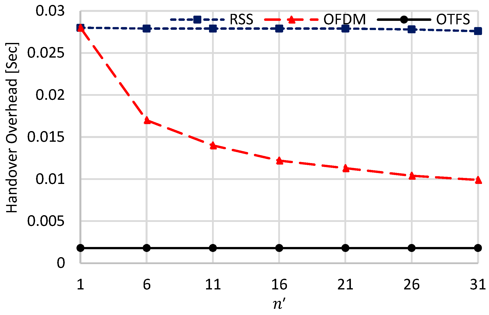
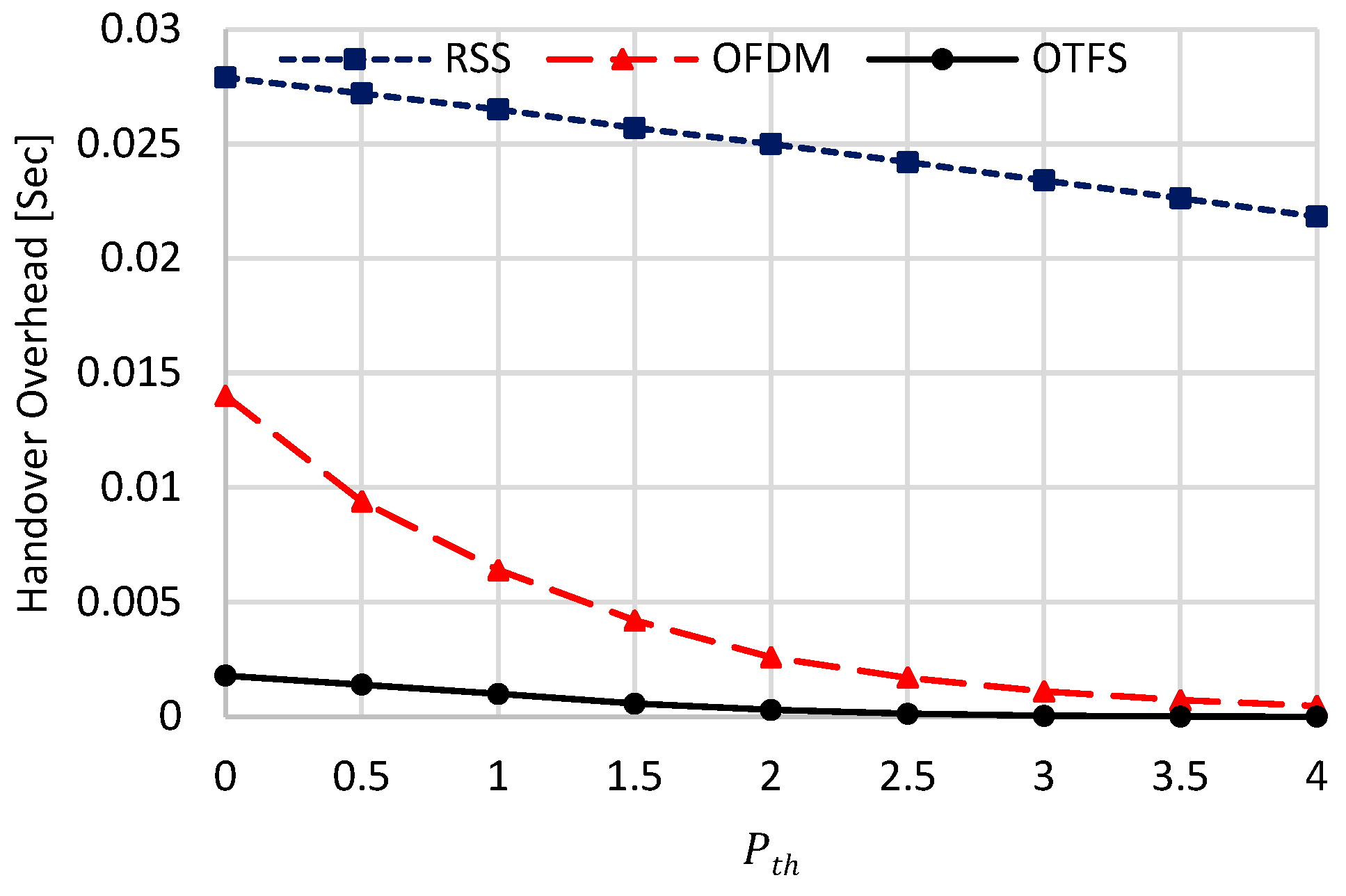
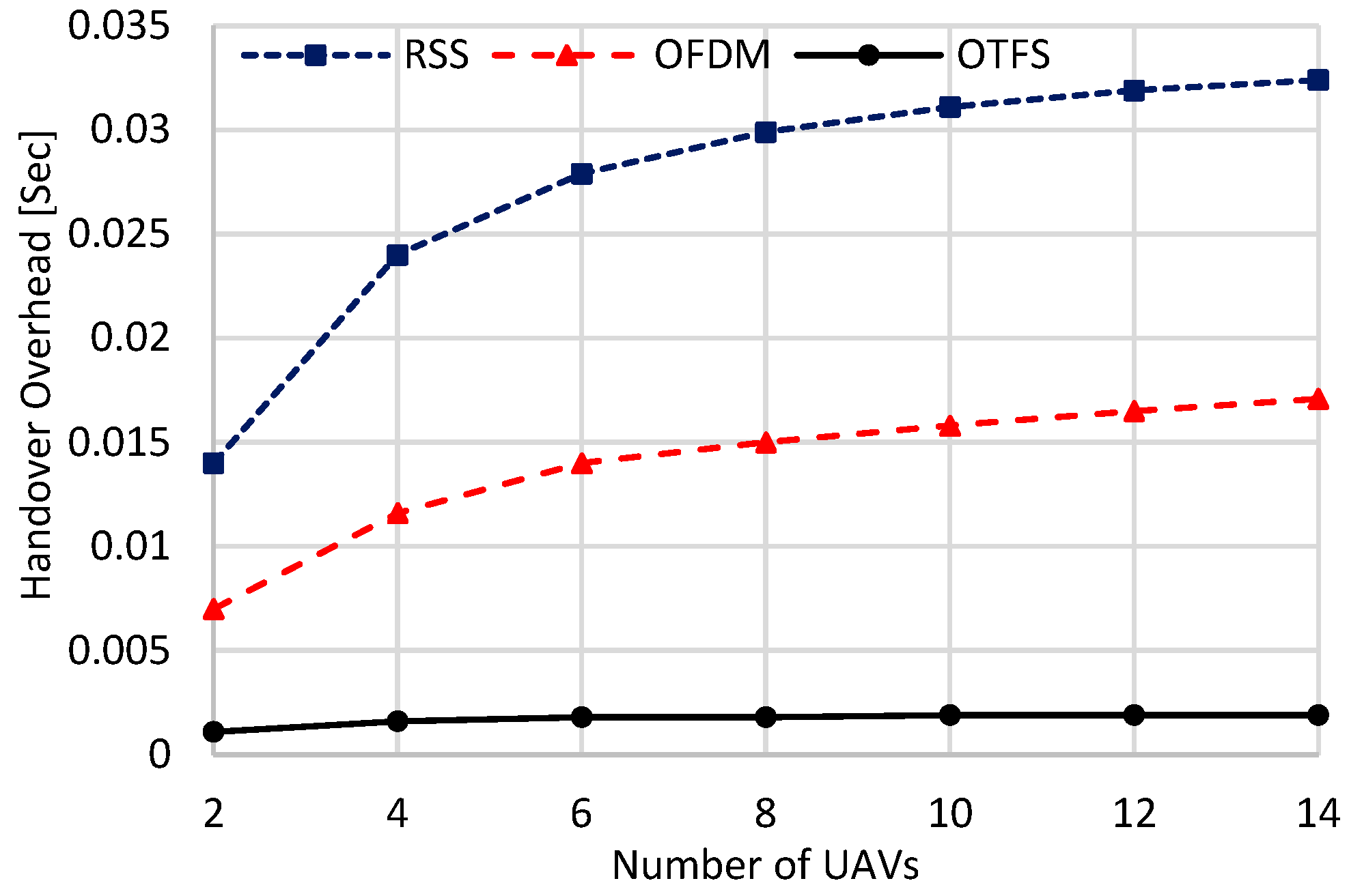
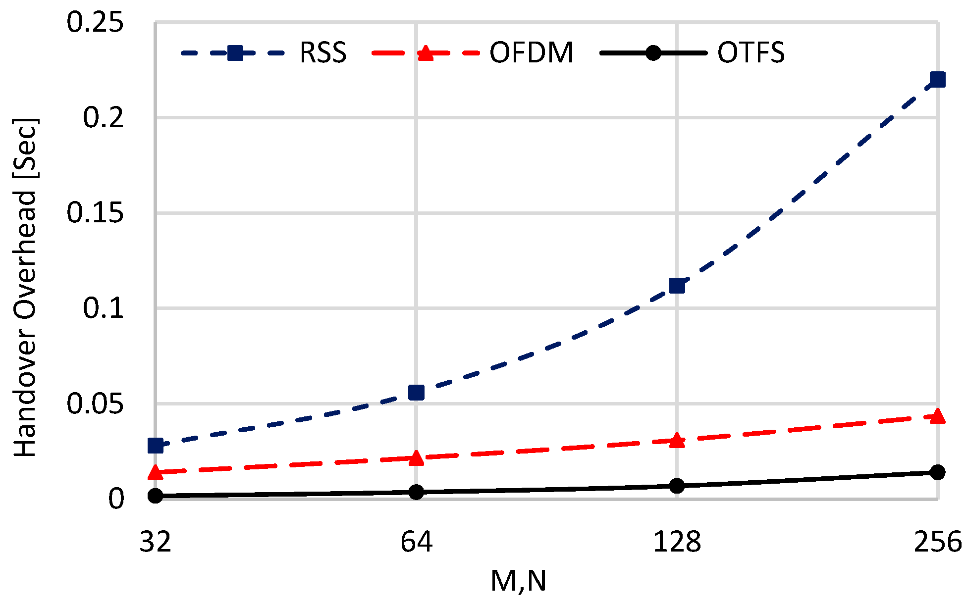
  • Handover Overhead [s], which is defined as follows [30]:
    O H O = N u m b e r   o f   H a n d o v e r s × S i n g l e   H a n d o v e r   d u r a t i o n
    Actually, there are many components of single-handover duration, including, channel estimation overhead, signaling overhead, processing delay, data packet loss and re-transmission delay, and synchronization time. In this paper, for fair comparisons, we were more concerned about physical-layer handover issues than the network-layer handover issues. Thus, we only considered channel estimation overhead, signaling overhead, and synchronization time. Also, we considered that only one packet can be used to do all this. Thus, the length of this packet will be P q T / M s in the case of RSS, a single OFDM symbol duration of T s in the case of OFDM, and a single OTFS symbol duration of N T s in the case of OTFS. Apparently, OTFS has the largest handover duration while the RSS scheme has the lowest one.
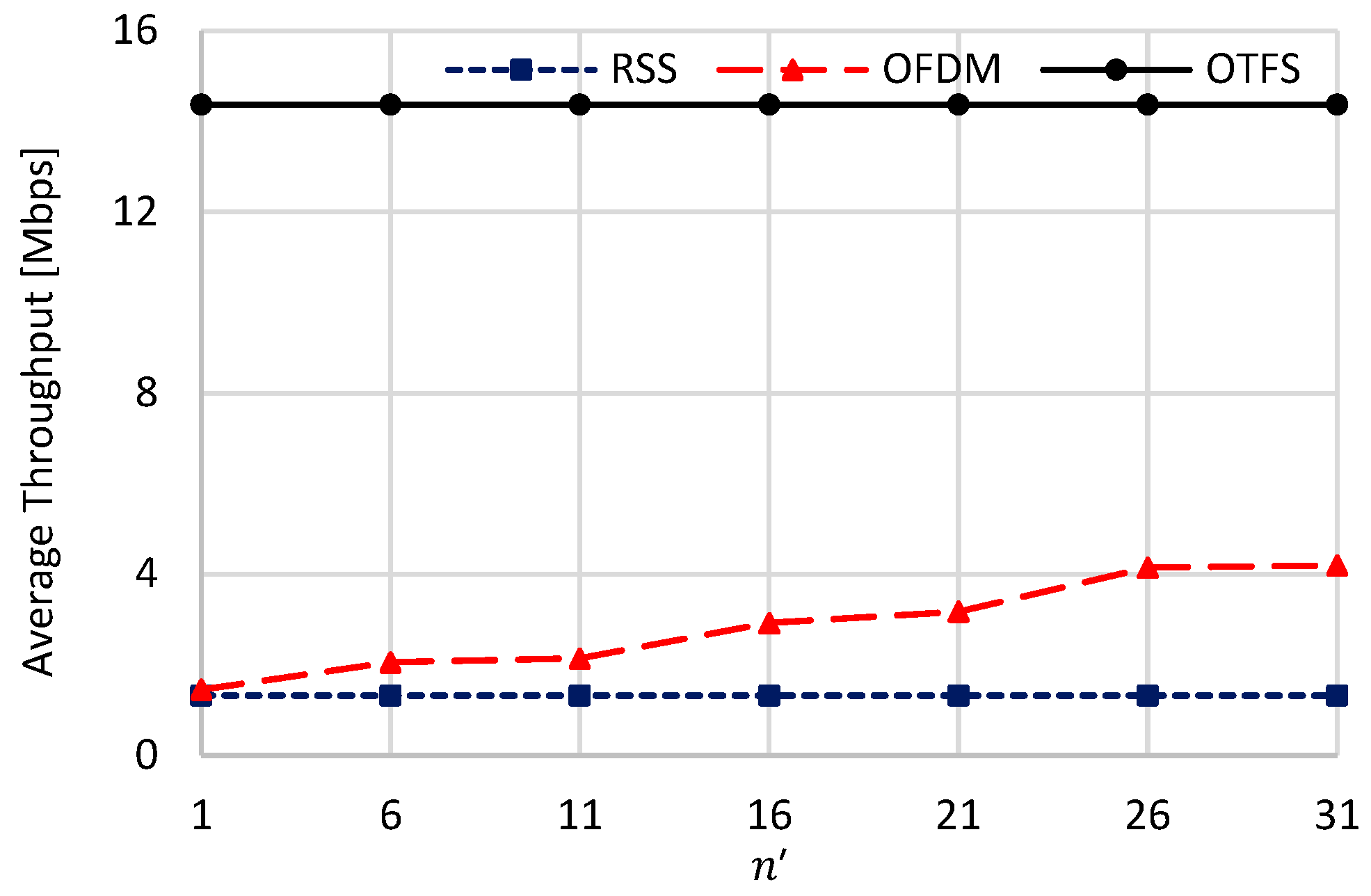
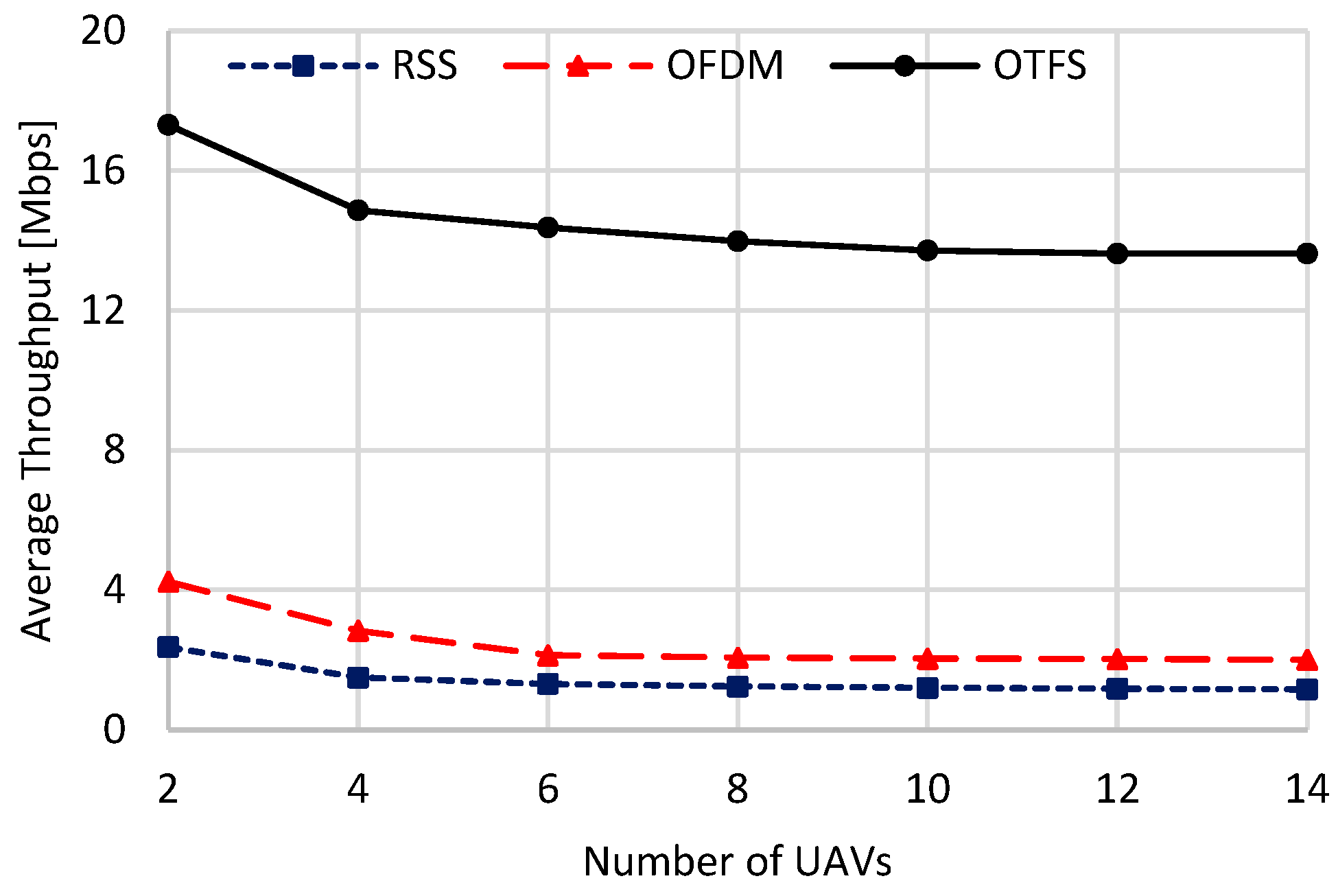
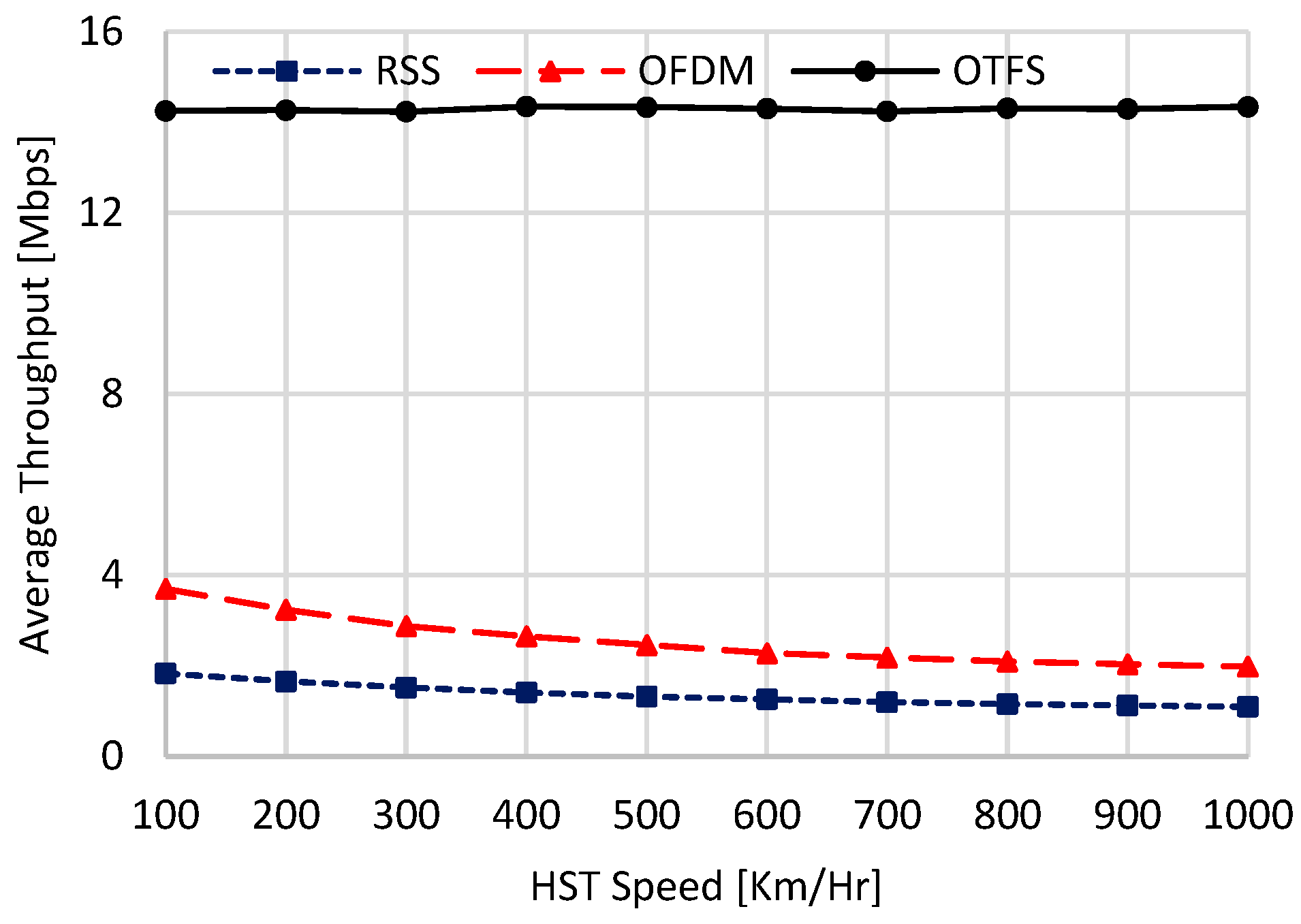
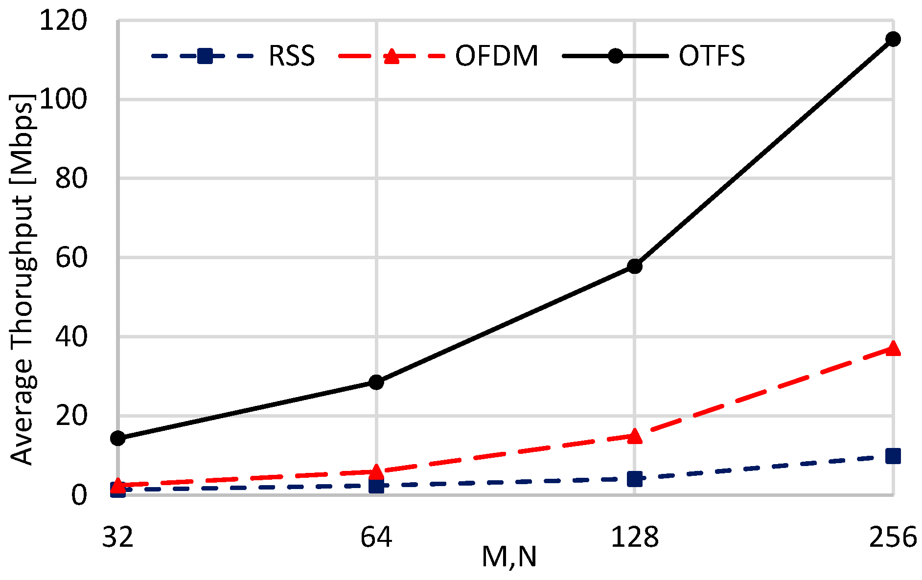
  • Average Throughput [bps]: For the average throughput calculation, we followed the formula given in [30]. In this formula, the average throughput is simply the data rate multiplied by the percentage of the handover overhead as follows:
    Ψ = M f ψ H ^ O T F S   s y m b o l s   d u r a t i o n O T F S   s y m b o l s   d u r a t i o n + H a n d o v e r   O v e r h e a d ,
    where M f ψ H ^ is the achievable average data rate resulting from multiplying the total bandwidth M f with the average spectral efficiency ψ H ^ given in (38), and the ratio O T F S   s y m b o l s   d u r a t i o n O T F S   s y m b o l s   d u r a t i o n + H a n d o v e r   O v e r h e a d < 1 is the loss in the achievable data rate resulting from the accumulated handover overhead due to the transmission of the OTFS symbols.
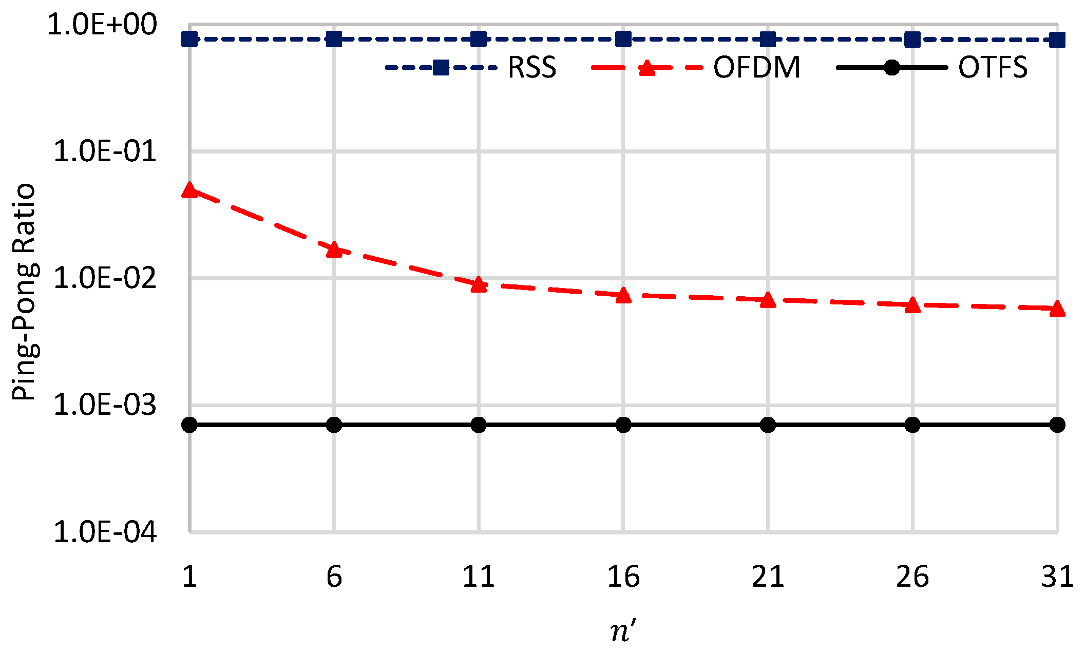
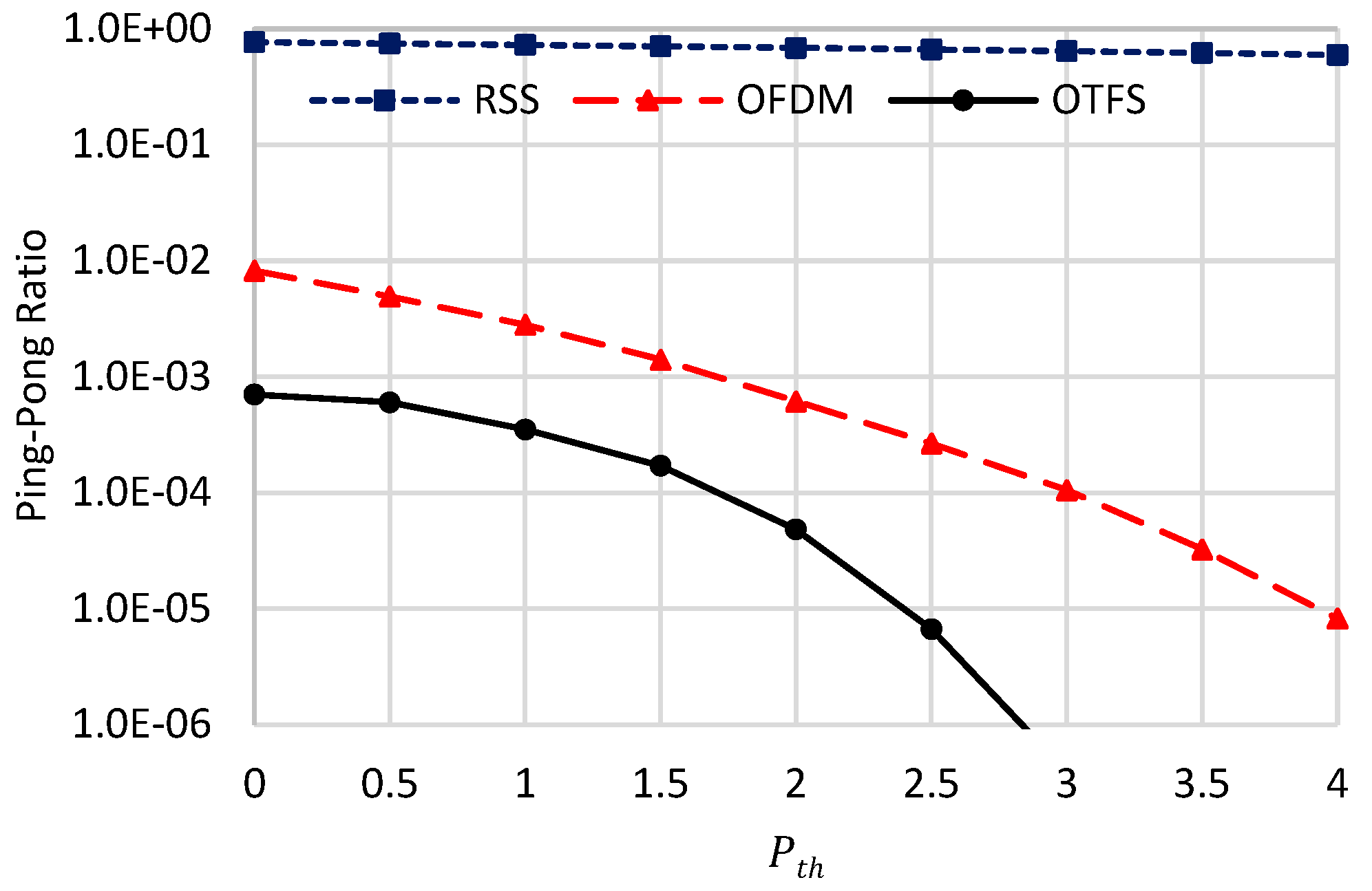
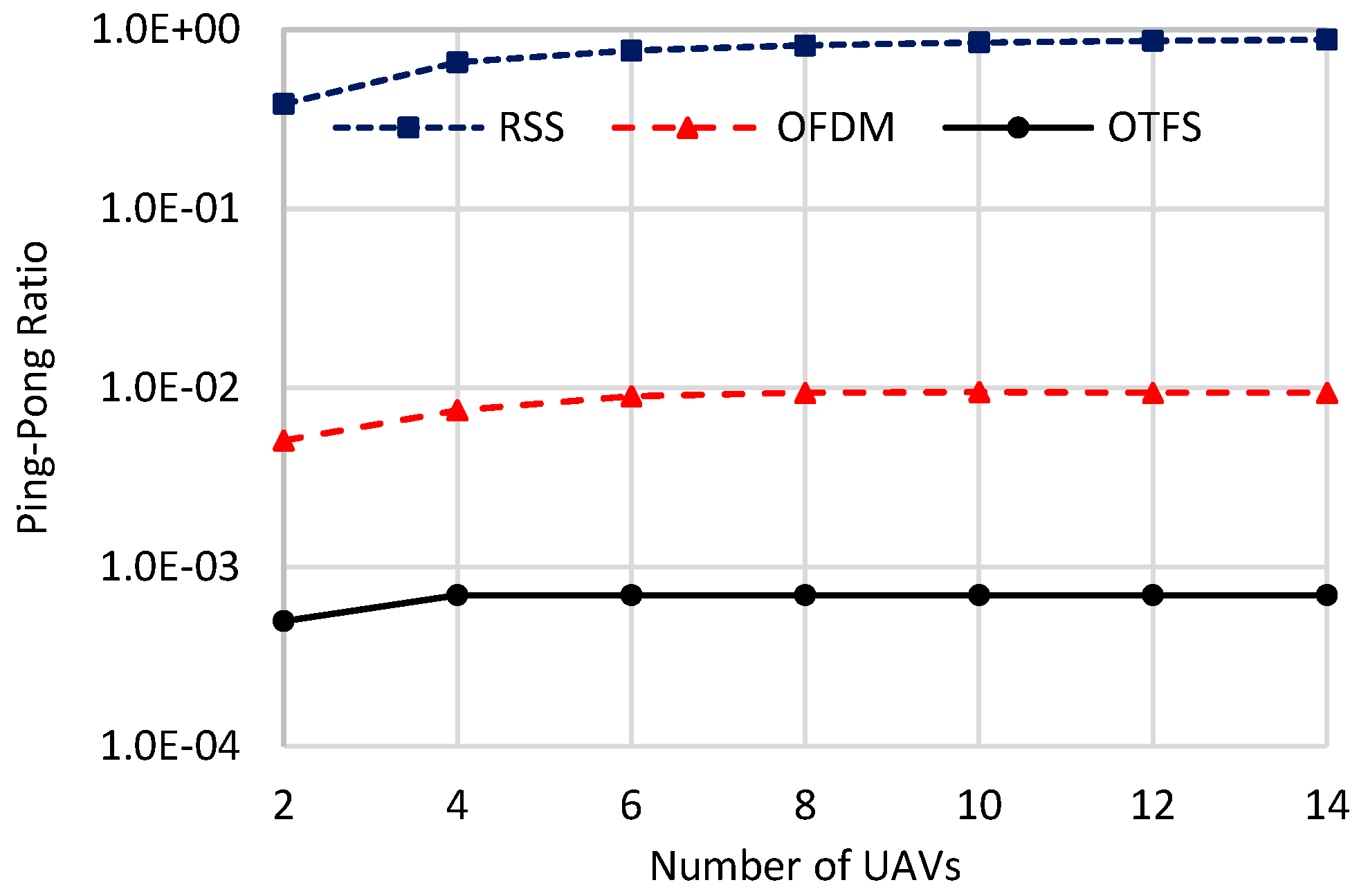
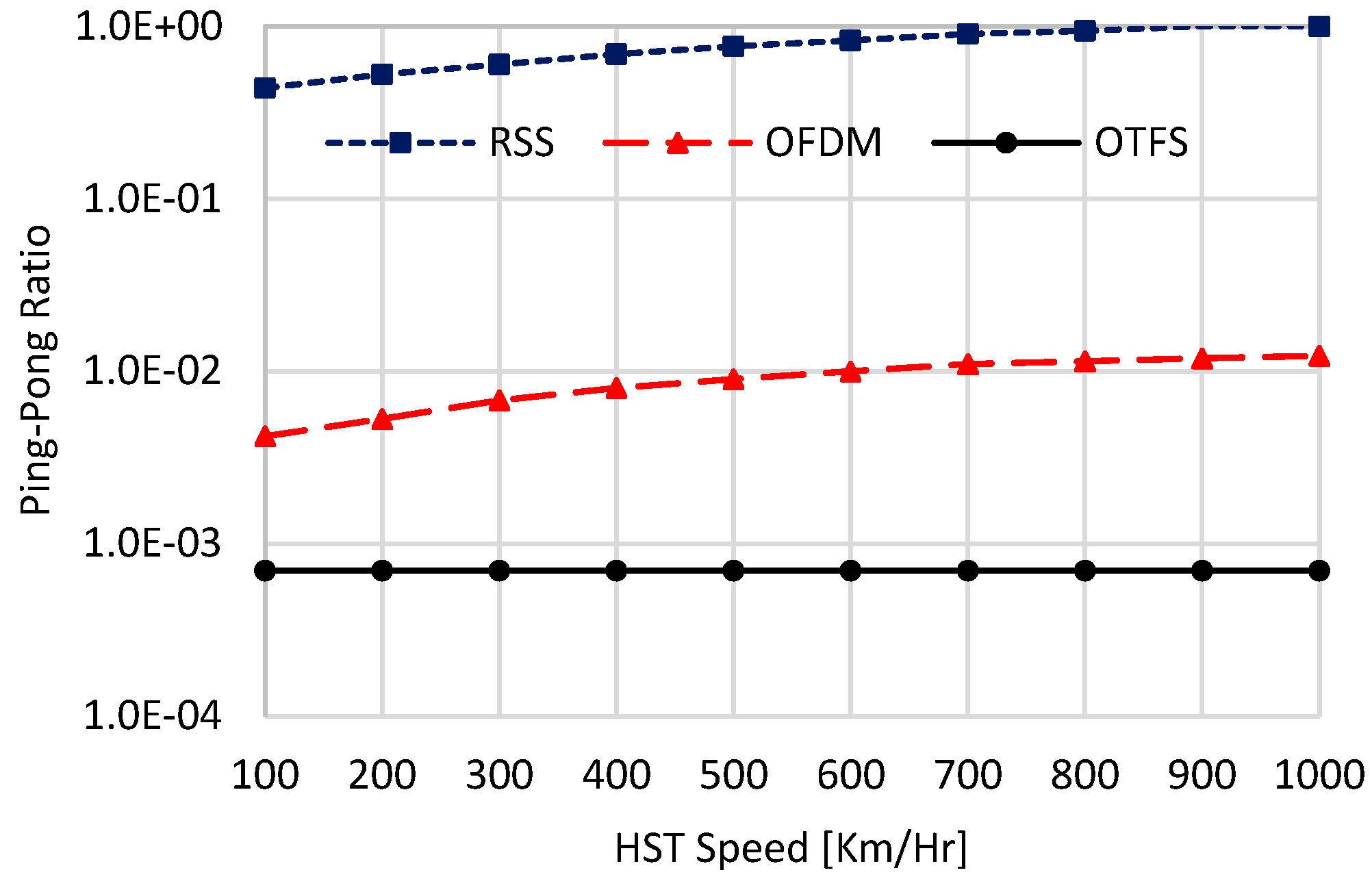
  • Ping-Pong Ratio, which is defined as the number of handovers, where the HST switches back and forth to the same UAV, divided by the total number of handovers. This ratio can give an indication of the number of unnecessary false handovers, which highly degrades the overall system performance.
Table 2. Simulation parameters.
ParameterValue
f 5.06 GHz [8]
f 15 KHz [8]
M 32 [31]
N 32 [31]
α m a x 5.47 × 10⁻³ [8]
P q 17 [8]
σ g 2 −114 dBm
v 500 Km/Hr
n 12 [8]
P T x 10 Watts [8]
P t h 0

7.1. Studying the Effects of n and P t h

In this part of the numerical analysis, we investigate the performances of the schemes involved in the comparisons against the critical parameters n and P t h while considering perfect DD channel estimation, i.e., M S E H = 0 in (38). Also, the HST speed is set to 500   K m / H r , and six UAVs are used. As n decreases, i.e., decreasing the number of coherence periods, the DD channel will be highly time-varying, and vice versa. Similarly, as P t h decreases high number of handovers are expected, and vice versa.

7.1.1. Effect of n

Figure 3, Figure 4 and Figure 5 give the handover performance metrices against the value of n ranging from 1 to 31 while considering the worst scenario of P t h = 0   d B . In this regard, n = 1 means a highly time-varying DD CIR, while n = 31 means the DD CIR is almost constant over the whole OTFS symbol duration.
For the RSS strategy, the handover overhead is marginally decreased when increasing n . This is because RSS fluctuates at every chip duration due to the accumulated effect of multi-path and Doppler shift. Thus, changing the channel every T s, i.e., when n = 1 , or changing it every N T s, i.e., when n = 31 , will have almost the same impact on the RSS handover performance due to the highly fluctuating RSS in both cases. This is the reason why the handover metrices of the RSS schemes marginally changed when increasing n .
For OTFS, the handover overhead, the ping-pong ratio, and the average throughput are constant irrespective of the value of n . This comes from the constant h ^ D D l , k 2 value for a given n value as we proved in detail. The only difference between the low n values and the high n values reside in the DD channel sparsity. That is, the DD channel sparsity increases when decreasing n , and vice versa, but the DD channel gain h ^ D D l , k 2 is constant over the whole OTFS symbol for both cases. Thanks to this phenomenon, the proposed handover strategy has the lowest handover overhead and ping-pong ratio, while it has the highest average throughput in consequence.
Different from RSS and OTFS, the FT channel using OFDM is highly influenced by the value of n . When n = 1 , the DD channel changes at every OFDM symbol, and it will be too sparse, which highly increases ISI and ICI of the FT channel. This results in highly fluctuating the FT channel gain making the handover overhead, the average throughput, and the ping-pong ratio almost equal to that which belongs to the RSS strategy. Although both OFDM and RSS have the same handover overhead when n = 1 , they have different numbers of handovers, and they have different single-handover durations.
However, when n = 31 , the DD CIR is almost constant over the whole OTFS symbol and is less sparse, which decreases the ISI and ICI of the corresponding FT channel. This results in highly enhancing the handover metrics of the OFDM strategy, as shown in Figure 3, Figure 4 and Figure 5. From these figures, when n = 1 , the handover overhead and the ping-pong ratio of the OTFS-based handover are equal to 0.0643 (0.643) and 0.014 (9.1277 × 10⁻⁴) of that which belongs to OFDM (RSS), respectively. Also, its average throughput is higher than that which belongs to OFDM (RSS) by 9.93 (10.9) times.

7.1.2. Effect of P t h

Figure 6, Figure 7 and Figure 8 show the assessed handover metrices of the compared schemes against P t h using n = 12 , which is the rated n value for the HST scenario, as stated in [8], based on practical measurements. Generally, the handover overhead and the ping-pong ratio of all compared schemes are decreasing when increasing P t h , while their average throughput is increasing. This can be attributed to the trade-off coming from increasing the value of P t h . On the one hand, increasing P t h will always link the HST with a certain UAV for a long time period, decreasing both the handover duration and the ping pong ratio. On the other hand, the linkage with a certain UAV for a long time period will decrease the spectral efficiency of the HST, as it will be unable to connect with other UAVs with higher spectral efficiencies. Decreasing handover duration and the ping-pong ratio will increase the average throughput, while decreasing the spectral efficiency will decrease it for constant available bandwidth ( M f ) . As the handover overhead has a dominant effect over the spectral efficiency, its decrease due to increasing P t h will always result in increasing the achievable throughput till reaching a saturation point. The saturation happens when there are no other handovers between the current UAV and the other UAVs, resulting in Ψ = M f ψ H ^ , as given in (55). The proposed OTFS-based strategy has superior handover performances over the other benchmarks due to its constant DD channel gain over the whole OTFS symbol duration. From these figures, when P t h = 0   d B , the handover overhead of the proposed OTFS strategy is about 0.1286 (0.067) of that belonging to OFDM (RSS), respectively, and these values become 0.0036 (7.8 × 10⁻⁵) when P t h = 4   d B . For the ping-pong ratio, these values are 0.0854 (9.16 × 10⁻⁴) when P t h = 0   d B . For average throughput, the proposed OTFS-based handover strategy has higher throughput than OFDM (RSS) by 5.81 (10.8) times when P t h = 0   d B , and these values become 1.74 (15.64) when P t h = 4   d B . Also, we can conclude that the optimal P t h value for the proposed scheme, causing a saturation in the average throughput, is equal to 3.5 dB.

7.2. Against Number of UAVs

In this part of numerical analysis, we compare the handover performances of the candidate schemes against the number of deployed UAVs. In these simulations, we use n = 12 , an HST speed of 500   K m / H r , and the worst case of P t h = 0   d B . Also, we assume perfect DD channel estimation, i.e., M S E H = 0 in (38).
Figure 9, Figure 10 and Figure 11 show the handover overhead, the average throughput, and the ping-pong ratio of the compared schemes against the number of UAVs. Generally, as the number of UAVs increases, the handover overhead and the ping-pong ratio increase, while the average throughput decreases. This is because when increasing the number of UAVs, using P t h = 0   d B as a worst-case scenario, the HST will always be handed over among the deployed UAVs, as there will always be a high possibility of finding a better UAV with a higher data rate than the currently connected one. This possibility will be further increased as we increase the number of UAVs deployed, resulting in increasing the handover overhead and the ping-pong ratio, as given in Figure 9 and Figure 10. As given in (55), average throughput is inversely related to handover overhead, and the handover overhead has the dominant effect over the average data rate on the value of the average throughput. Thus, it declines when increasing the number of UAVs, as illustrated in Figure 10, due to the increased handover overhead depicted in Figure 9. Additionally, the handover metrices of all schemes saturate as the number of deployed UAVs grows. This is due to the high density of UAVs, which shortens the separation distances among candidate UAVs. As a result, candidate UAVs offer nearly equal handover metrics, leading to a saturation in their performance. From these figures, the proposed scheme achieves significant improvements in handover metrics compared to other schemes. It also exhibits the lowest rates of increase in handover overhead and ping-pong ratio, as well as the lowest rate of decrease in average throughput. This superior handover performance is attributed to its stable handover decisions, resulting from constant DD channel gains. As a numerical example, when the number of UAVs is equal to two, the proposed scheme achieves 0.001 s, 17.3 Mbps, and 0.0005 for the handover overhead, the average throughput, and the ping-pong ratio, respectively. However, the OFDM (RSS) scheme achieves 0.007 (0.014) s, 4.2 (2.3) Mbps, and 0.0051 (0.384), respectively. When the number of UAVs is set to 14, the proposed scheme achieves a handover overhead of 0.0019 s, average throughput of 13.6 Mbps, and ping-pong ratio of 7 × 10⁻⁴. However, the OFDM (RSS) scheme achieves 0.0171 (0.0324) s, 2.03 (1.16) Mbps, and 0.0084 (0.8816) for handover overhead, average throughput, and ping-pong ratio, using 14 UAVs, respectively.

7.3. Against HST Speed

In this part of numerical analysis, we study the effect of the HST speed on the performance of the schemes involved in the comparison. Figure 12, Figure 13 and Figure 14 show the performances of the compared schemes against different HST speeds in Km/Hr. In these simulations, six deployed UAVs with n = 12 and the worst case of P t h = 0   d B are used. Also, perfect DD channel estimation, i.e., M S E H = 0 in (38) is considered. These figures validate the hypothesis that the proposed OTFS-based handover-triggering mechanism delivers superior and sustainable handover performance, independent of the HST speed. This resilience is attributed to the DD channel’s unique ability to resolve channel gains in the DD domain, resulting in gains that remain constant over each OTFS symbol duration, even at high HST speeds. In contrast, the handover performance of the other two candidate mechanisms, particularly the RSS-based approach, is considerably affected by variations in HST speed. The RSS-based handover triggering is especially sensitive to speed-induced fluctuations because it encapsulates ISI and cumulative Doppler effects across all frequencies, leading to rapid signal strength variations.
In OFDM, the Doppler shift impacts each subcarrier according to its specific frequency, creating lower FT channel fluctuations than RSS, mainly due to ICI. As a result, the OFDM-based handover mechanism achieves higher stability than RSS-triggered handover, as reflected by these figures. However, the performance of OFDM-based handover remains substantially inferior to that of OTFS, which provides a more consistent and high-performing handover strategy under high-speed conditions. As a numerical example, when the HST speed is equal to 100 Km/Hr, the proposed scheme achieves 0.0018 s, 14.3 Mbps, and 0.0007 for the handover overhead, the average throughput, and the ping-pong ratio, respectively. However, the OFDM (RSS) scheme achieves 0.0084 (0.012) s, 3.7 (1.71) Mbps, and 0.0042 (0.44), respectively. When the HST speed is set to 1000 Km/Hr, the proposed scheme achieves the same handover performances as the case of 100 Km/Hr. However, the handover metrices are highly deteriorated for OFDM (RSS) scheme, which achieves 0.0175 (0.039) s, 1.98 (1.01) Mbps, and 0.0113 (1) for handover overhead, average throughput, and ping-pong ratio, respectively. These results reveal that at extremely high speeds, e.g., 1000 Km/Hr, the ping-pong ratio of the RSS-based handover triggering reaches one. This indicates that nearly all handovers initiated by the RSS scheme at this speed are unnecessary.

7.4. Against N and M Values

In this part of the numerical analysis, we study the effect of the critical parameters M and N on the handover performances of the compared schemes. In these simulations, six UAVs, an HST speed of 500 Km/Hr, P t h = 0 , n = 12 , and perfect channel estimation are considered. Figure 15, Figure 16 and Figure 17 show the handover overhead, the average throughput, and the ping-pong ratio of the compared schemes against increasing the values of M and N. Figure 15 illustrates the handover overhead associated with the evaluated schemes as a function of the parameters M and N . As observed in the figure, when M and N are doubled, the handover overhead in the RSS scheme also doubles. This phenomenon arises due to the increased number of handovers resulting from the extended OTFS symbol duration, as given in (54). For OTFS, although the number of handovers remains unchanged as we increase M and N , the single handover duration increases proportionally with them. Consequently, this leads to a marginal increase in its overall handover overhead compared to RSS, as depicted in Figure 15. Similarly, in OFDM, the single handover duration is increased when increasing the value of M , resulting in slightly increasing its overall handover overhead. However, its rate of increase is lower than OTFS, indicating a lower number of handovers as we increase the value of M and N . As a quantitative example, when M and N increase from 32 to 256, the handover overhead in the RSS scheme exhibits a 7.8-fold increase. In contrast, the corresponding increases for OFDM and OTFS are 2.42-fold and 8.23-fold, respectively. Notably, the rate of increase in handover overhead for OFDM is the lowest among the evaluated schemes, demonstrating that it does not scale linearly with M and N . This can be attributed to the improved averaging process inherent in OFDM symbols, which effectively mitigates handover frequency, reducing the number of handovers, and enhances its handover performance. Nevertheless, OTFS exhibits the most superior performance overall.
Figure 16 presents the average throughput of the evaluated schemes as a function of M and N . All schemes exhibit performance gains with increasing M and N , primarily due to the corresponding rise in achievable data rate ( M f ψ H ^ ), resulting from the expanded allocated bandwidth ( M f ) , as described in (55). Owing to the dominant impact of ( M f ) over the ratio O T F S   s y m b o l s   d u r a t i o n O T F S   s y m b o l s   d u r a t i o n + H a n d o v e r   O v e r h e a d , Ψ of OTFS nearly doubles when M and N are doubled due to its marginal increase in handover overhead as given in Figure 15. In contrast, the OFDM scheme exhibits an increase in Ψ that exceeds a factor of two when doubling the values of M and N , a behavior attributed to its enhanced handover strategy arising from the averaging process over large M and N values. Meanwhile, the RSS scheme does not attain an exact doubling of Ψ , owing to its increased handover overhead, as illustrated in Figure 15. As a numerical example, when M and N increase from 32 to 256, the average throughput in the RSS scheme improves by a factor of 7. By comparison, OFDM and OTFS attain improvements of 15.1-fold and 7.98-fold, respectively. These findings confirm both the superior performance of the proposed OTFS scheme and the significant enhancements in OFDM performance with increasing M and N .
Figure 17 depicts the ping-pong ratio of the evaluated schemes as M and N increase. Due to the higher number of handovers, the RSS scheme exhibits an elevated ping-pong ratio, which approaches nearly 100% when M and N are both set to 256. It is interesting to note that, although the handover overhead of both OTFS and OFDM increases with larger M and N , their ping-pong ratios decrease. This is because the additional overhead in OTFS and OFDM arises from a longer duration per handover, rather than a greater number of handovers, as we previously explained. In fact, for OFDM, the number of handovers declines at higher values of M and N , attributed to the enhanced averaging process. Consequently, the ping-pong ratio of both OTFS and OFDM diminishes as M and N grow, as shown in Figure 17. For instance, when M and N increase from 32 to 256, the ping-pong ratio of the RSS scheme grows by a factor of 1.27. In contrast, the ping-pong ratios of OFDM and OTFS are reduced by factors of 16.3462 and 63.9, respectively. These findings affirm the superior performance of the proposed OTFS scheme across all tested values of M and N .

7.5. Effect of Channel Estimation Error

Figure 18 studies the effect of channel estimation error on the average throughput performance of the proposed scheme using 6 UAVs and an HST speed of 500 Km/Hr under different P t h values. In the aforementioned mathematical analysis, we proved that both M S E H , L S and M S E H , M M S E are less than σ g 2 . Thus, we will measure the average throughput against the normalized channel estimation error M S E H / σ g 2 ranging from 0 to 1. In this context, 0 means exact CIR information without any channel estimation error, and 1 indicates the utmost channel estimation error where M S E H reaches σ g 2 , which does not occur, as proven in (42) and (53). From these figures, as the channel estimation error increases, a small degradation in the average throughput is obtained for all tested P t h values. This comes from the marginal effect of the channel estimation error on the performance of the proposed scheme, as proven in (42) and (53) using LS and MMSE OTFS channel estimators. For example, the average throughput only decreases by 4.8%, 3.38%, 2.76% for P t h = 0 d B , 1.5 dB, and 3 dB, respectively, when increasing the normalized channel estimation error from 0 to 1. This figure shows that as P t h increases, the rate at which average throughput decreases slows down.

8. Conclusions

In this paper, we have investigated the problem of handover triggering in UAV-to-ground communication networks, where the UAVs and/or ground entities are flying/moving too fast. Instead of the conventional highly time-varying handover-triggering schemes based on RSS or FT channel gains using OFDM modulation, we introduced a handover strategy based on the estimated DD channel gains using OTFS modulation. This is motivated by the fact that DD channel gains are stable and constant over the whole OTFS symbol duration. By mathematical analysis, we proved that channel estimation errors using LS or MMSE have marginal effects on the spectrum efficiency performance of the proposed scheme. By numerical analysis, we proved the high potency of the proposed scheme over RSS and OFDM in terms of handover overhead, average throughput, and ping-pong ratio under different scenarios. Also, we bound the effect of channel estimation error on the performance of the proposed scheme via numerical simulations. The numerical results revealed the high efficiency of the proposed scheme over other benchmarks, where it outperforms their average throughput performance tens of times in ultra-high-speed scenarios. While this paper focuses on the UAV-to-ground scenario, the proposed OTFS-band handover approach is adaptable to any highly dynamic communication applications without requiring any modifications. Also, the DD channel framework facilitates optimization of the UAV trajectory by dynamically adjusting its velocity and direction to align with the motion of the ground entity. This approach significantly mitigates the frequency of handover requests, thereby enhancing handover performance. Nevertheless, further investigation is warranted to comprehensively address this aspect, which is deferred to future research endeavors.

Author Contributions

Conceptualization, E.M.M. and H.S.H.; methodology, E.M.M. software, E.M.M.; validation, E.M.M., M.A.A. and S.H.; formal analysis, E.M.M.; investigation, E.M.M.; resources, E.M.M. and M.A.A.; writing—original draft preparation, E.M.M.; writing—review and editing, H.S.H., M.A.A. and S.H.; visualization, S.H.; project administration, E.M.M.; funding acquisition, E.M.M. and H.S.H. All authors have read and agreed to the published version of the manuscript.

Funding

The authors extend their appreciation to Prince Sattam bin Abdulaziz University for funding this research work through the project number (PSAU/2024/01/30944).

Data Availability Statement

The original contributions presented in this study are included in the article. Further inquiries can be directed to the corresponding author.

Conflicts of Interest

The authors declare no conflicts of interest.

Appendix A

Converting (41) into matrix vector multiplication using G D D = 1 N G D T F N results in
M S E H , L S = 1 M N 1 N G D T F N F 2 ,  
where . F means the Frobenius norm of a matrix, which can be re-written as follows:
M S E H , L S = 1 M N 3 T r G D T F N G D T F N , M S E H , L S = 1 M N 3 T r G D T F N G D T F N , = 1 M N 3 T r G D T F N F N G D T = 1 M N 2 T r G D T I N G D T = 1 M N 2 T r G D T G D T = 1 M N 2 T r N I M σ g 2 ,   57
which completes the proof of (42).

Appendix B

From [32], for any positive definite matrix A C P × P , T r A 1 P 2 T r A . Thus, from (51)
M S E H , M M S E Q P 2 T r φ e Ω g o , D T 1 φ e + Ω h 1 ,  
where
T r φ e Ω g o , D T 1 φ e + Ω h 1 = T r φ e φ e σ o 2 i = 1 Q P σ h i 2 + σ g 2 + i = 1 Q P 1 σ h i 2 ,  
From (46),
T r φ e φ e = T r i = 1 Q P Θ i s D D e Θ i s D D e = T r i = 1 Q P s D D e Θ i Θ i s D D e ,  
where
Θ i Θ i = F N I R x Τ α i Σ β i F N I T x F N I R x Τ α i Σ β i F N I T x , = Τ α i Σ β i F N I T x F N I R x F N I R x Τ α i Σ β i F N I T x = N Τ α i Σ β i F N I T x I M N Τ α i Σ β i F N I T x = N F N I T x Τ α i Σ β i Τ α i Σ β i F N I T x = N F N I T x Σ β i Τ α i Τ α i Σ β i F N I T x = N F N I T x Σ β i I M N Σ β i F N I T x = N F N I T x Σ β i Σ β i F N I T x = N F N I T x I M N F N I T x = F N I T x F N I T x = N 2 I M N ,
Then
T r φ e φ e = T r i = 1 Q P s D D e Θ i Θ i s D D e = T r N 2 i = 1 Q P s D D e I M N s D D e = Q P M N 3 σ e 2 .  
Substituting (A7) in (A4) and then in (A3) completes the proof of (52).

References

  1. Alnakhli, M.A.; Mohamed, E.M.; Fouda, M.M. Bandwidth allocation and power control optimization for multi-UAVs enabled 6G network. IEEE Access 2024, 12, 67405–67415. [Google Scholar] [CrossRef]
  2. Alnakhli, M.; Mohamed, E.M.; Abdulkawi, W.M.; Hashima, S. Joint User Association and Power Control in UAV Network: A Graph Theoretic Approach. Electronics 2024, 13, 779. [Google Scholar] [CrossRef]
  3. Mohamed, E.M.; Alnakhli, M.; Fouda, M.M. Joint UAV Trajectory Planning and LEO-Sat Selection in SAGIN. IEEE Open J. Commun. Soc. 2024, 5, 1624–1638. [Google Scholar] [CrossRef]
  4. Amrallah, A.; Mohamed, E.M.; Tran, G.K.; Sakaguchi, K. UAV Trajectory Optimization in a Post-Disaster Area Using Dual Energy-Aware Bandits. Sensors 2023, 23, 1402. [Google Scholar] [CrossRef]
  5. Zheng, J.; Zhu, Q.; Jamalipour, A. Content Delivery Performance Analysis of a Cache-Enabled UAV Base Station Assisted Cellular Network for Metaverse Users. IEEE J. Sel. Areas Commun. 2024, 42, 643–657. [Google Scholar] [CrossRef]
  6. Mohamed, E.M.; Hashima, S.; Hatano, K. Energy Aware Multiarmed Bandit for Millimeter Wave-Based UAV Mounted RIS Networks. IEEE Wirel. Commun. Lett. 2022, 11, 1293–1297. [Google Scholar] [CrossRef]
  7. Li, D.; Xu, S.; Zhao, C.; Wang, Y.; Xu, R.; Ai, B. Data Collection in Laser-Powered UAV-Assisted IoT Networks: Phased Scheme Design Based on Improved Clustering Algorithm. IEEE Trans. Green Commun. Netw. 2024, 8, 482–497. [Google Scholar] [CrossRef]
  8. Ma, Y.; Ma, G.; Ai, B.; Fei, D.; Wang, N.; Zhong, Z.; Yuan, J. Characteristics of Channel Spreading Function and Performance of OTFS in High-Speed Railway. IEEE Trans. Wirel. Commun. 2023, 22, 7038–7054. [Google Scholar] [CrossRef]
  9. He, Y.; Huang, W.; Wei, H.; Zhang, H. Effect of Channel Fading and Time-to-Trigger Duration on Handover Performance in UAV Networks. IEEE Commun. Lett. 2021, 25, 308–312. [Google Scholar] [CrossRef]
  10. Tayyab, M.; Gelabert, X.; Jäntti, R. A Survey on Handover Management: From LTE to NR. IEEE Access 2019, 7, 118907–118930. [Google Scholar] [CrossRef]
  11. Nor, A.M.; Mohamed, E.M. Li-Fi Positioning for Efficient Millimeter Wave Beamforming Training in Indoor Environment. Mob. Netw. Appl. 2019, 24, 517–531. [Google Scholar] [CrossRef]
  12. Hadani, R.; Rakib, S.; Tsatsanis, M.; Monk, A.; Goldsmith, A.J.; Molisch, A.F.; Calderbank, R. Orthogonal Time Frequency Space Modulation. In Proceedings of the 2017 IEEE Wireless Communications and Networking Conference (WCNC), San Francisco, CA, USA, 19–22 March 2017; pp. 1–6. [Google Scholar] [CrossRef]
  13. Hong, Y.; Thaj, T.; Viterbo, E. Delay-Doppler Communications: Principles and Applications; Academic Press: Cambridge, MA, USA, 2022; ISBN 9780323850285. [Google Scholar]
  14. Thaj, T.; Viterbo, E. Low Complexity Iterative Rake Decision Feedback Equalizer for Zero-Padded OTFS Systems. IEEE Trans. Veh. Technol. 2020, 69, 15606–15622. [Google Scholar] [CrossRef]
  15. Zhang, H.; Huang, X.; Zhang, J.A. Low-Overhead OTFS Transmission with Frequency or Time Domain Channel Estimation. IEEE Trans. Veh. Technol. 2024, 73, 799–811. [Google Scholar] [CrossRef]
  16. Zieliński, T.P.; Karpovich, P.; Abratkiewicz, K.; Maksymiuk, R.; Samczyński, P.; Duda, K.; Wypich, M. Wireless OTFS-Based Integrated Sensing and Communication for Moving Vehicle Detection. IEEE Sens. J. 2024, 24, 6573–6583. [Google Scholar] [CrossRef]
  17. Shang, H.; Chen, R.; Zhang, H.; Ma, G.; He, R.; Ai, B.; Zhong, Z. OTFS modulation and PAPR reduction for IoT-railways. China Commun. 2023, 20, 102–113. [Google Scholar] [CrossRef]
  18. Lin, H.; Yuan, J. Orthogonal Delay-Doppler Division Multiplexing Modulation. IEEE Trans. Wirel. Commun. 2022, 21, 11024–11037. [Google Scholar] [CrossRef]
  19. Arunkumar, K.P.; Murthy, C.R. Orthogonal delay scale space modulation: A new technique for wideband time-varying channels. IEEE Trans. Signal Process. 2022, 70, 2625–2638. [Google Scholar]
  20. Jang, Y.; Raza, S.M.; Kim, M.; Choo, H. Proactive Handover Decision for UAVs with Deep Reinforcement Learning. Sensors 2022, 22, 1200. [Google Scholar] [CrossRef]
  21. Sharma, V.; Song, F.; You, I.; Chao, H.-C. Efficient Management and Fast Handovers in Software Defined Wireless Networks Using UAVs. IEEE Netw. 2017, 31, 78–85. [Google Scholar] [CrossRef]
  22. Fujieda, K.; Kimura, T.; Takine, T. Handover Analysis in Aerial Base Station Networks with Different Altitudes. IEEE Commun. Lett. 2024, 28, 138–142. [Google Scholar] [CrossRef]
  23. Angjo, J.; Shayea, I.; Ergen, M.; Mohamad, H.; Alhammadi, A.; Daradkeh, Y.I. Handover Management of Drones in Future Mobile Networks: 6G Technologies. IEEE Access 2021, 9, 12803–12823. [Google Scholar] [CrossRef]
  24. Liu, D.; Xu, Y.; Wang, J.; Chen, J.; Yao, K.; Wu, Q.; Anpalagan, A. Opportunistic UAV Utilization in Wireless Networks: Motivations, Applications, and Challenges. IEEE Commun. Mag. 2020, 58, 62–68. [Google Scholar] [CrossRef]
  25. Ma, Y.; Ma, G.; Ai, B.; Wang, N.; Zhong, Z. Impacts of Time-Varying Channel Spreading Function on the OTFS Modulation System. IEEE Trans. Veh. Technol. 2024, 73, 10744–10749. [Google Scholar] [CrossRef]
  26. Raviteja, P.; Hong, Y.; Viterbo, E.; Biglieri, E. Practical Pulse-Shaping Waveforms for Reduced-Cyclic-Prefix OTFS. IEEE Trans. Veh. Technol. 2019, 68, 957–961. [Google Scholar] [CrossRef]
  27. Shen, W.; Dai, L.; Fan, P.A.J.; Heath, R.W. Channel Estimation for Orthogonal Time Frequency Space (OTFS) Massive MIMO. IEEE Trans. Signal Process. 2019, 67, 4204–4217. [Google Scholar] [CrossRef]
  28. Mishra, H.B.; Singh, P.; Prasad, A.K.; Budhiraja, R. OTFS Channel Estimation and Data Detection Designs with Superimposed Pilots. IEEE Trans. Wirel. Commun. 2022, 21, 2258–2274. [Google Scholar] [CrossRef]
  29. Sayana, K.; Zhuang, J.; Stewart, K. Channel Estimation Modeling for System Simulations. IEEE 802.16 Working Group on Broadband Wireless Access Standards, 2007, IEEE C802.16m-07/208. Available online: https://ieee802.org/16/tgm/contrib/C80216m-07_208r4.pdf (accessed on 26 February 2025).
  30. Neetu, R.R.; Ghatak, G.; Bohara, V.A.; Srivastava, A. Performance Analysis of Cache-Enabled Handover Management for Vehicular Networks. IEEE Trans. Netw. Sci. Eng. 2024, 11, 1151–1164. [Google Scholar]
  31. Mohamed, E.M.; Fouda, M.M. OTFS-Based Proactive Dynamic UAV Positioning for High-Speed Train Coverage. IEEE Open J. Commun. Soc. 2024, 5, 5718–5734. [Google Scholar] [CrossRef]
  32. Ulukök, Z.; Türkmen, R. On some matrix trace inequalities. J. Inequalities Appl. 2010, 2010, 1–8. [Google Scholar] [CrossRef]
Figure 1. Handover scenarios in aerial-to-ground network: (a) A fixed-wing airplane switches among different GBSs to maintain continuous connectivity. (b) A car in the roadway switches between multiple UAVs working as ABSs for seamless communication. (c) An HST switches between multiple UAVs working as ABSs for relaying information and providing continuous wireless coverage in hard-to-reach areas.
Drones 09 00185 g001
Figure 2. Baseband block diagram of the proposed DD channel gain-based handover triggering using OTFS modulation.
Drones 09 00185 g002
Figure 3. Handover overhead against n .
Drones 09 00185 g003
Figure 4. Average throughput against n .
Drones 09 00185 g004
Figure 5. Ping-pong ratio against n .
Drones 09 00185 g005
Figure 6. Handover overhead against P t h .
Drones 09 00185 g006
Figure 7. Average throughput against P t h .
Drones 09 00185 g007
Figure 8. Ping-pong ratio against P t h .
Drones 09 00185 g008
Figure 9. Handover overhead against the number of UAVs.
Drones 09 00185 g009
Figure 10. Average throughput against the number of UAVs.
Drones 09 00185 g010
Figure 11. Ping-pong ratio against the number of UAVs.
Drones 09 00185 g011
Figure 12. Handover overhead against HST speed.
Drones 09 00185 g012
Figure 13. Average throughput against HST speed.
Drones 09 00185 g013
Figure 14. Ping-pong ratio against HST speed.
Drones 09 00185 g014
Figure 15. Handover overhead against the values of M and N .
Drones 09 00185 g015
Figure 16. Average throughput against the values of M and N . .
Drones 09 00185 g016
Figure 17. Ping-pong ratio against the value of M and N .
Drones 09 00185 g017
Figure 18. Effect of channel estimation error on the OTFS average throughput.
Drones 09 00185 g018
Table 1. List of symbols.
SymbolDefinition
h i q Complex amplitude of channel path i in the coherence period q
Q Number of coherence periods
T OFDM symbol duration
M Number of subcarriers in the OTFS symbol
N Number of Doppler taps in the OTFS symbol
f Subcarrier spacing
n T Duration of each coherence period
NTOTFS symbol duration
P q Number of paths) in the q -th coherence period
α i q Delay spread of channel path i in the coherence period q
β i q Doppler shift in channel path i in the coherence period q
h q D D DD   CIR   of   the   q -th coherence period
l Normalized delay dimension in the DD grid
k Normalized Doppler dimension in the DD grid
β m a x Maximum Doppler frequency of the channel
α m a x Maximum delay spread of the channel
f Operating frequency
v Speed of the object
c Speed of light
s D D Tx DD QAM symbols
F N N-point DFT matrix
F M M-point DFT matrix
s F T Tx FT symbols
x D T Tx continuous DT signal
b T x Tx windowing function
I M Identity matrix
g D T AWGN in DT domain
r D T Rx continuous DT signal
Τ α i q Permutation matrix related α i q
Σ β i q Diagonal matrix containing the effect of β i q
y F T Rx FT symbols
H F T FT CIR
b R x Rx windowing function
y D D Rx DD QAM symbols
G D D AWGN in DD domain
H O Handover
R S S Received signal strength
TTTTime to trigger
P t h Threshold power
N S y m O F D M Number of OFDM symbols
N S y m t h Number of threshold symbols
N S y m O T F S Number of OTFS symbols
M S E Minimum square error
ψ H ^ Spectral efficiency
P T x Tx power
σ g 2 AWGN power
σ h 2 Channel power
O H O Handover overhead
Ψ Average throughput
Disclaimer/Publisher’s Note: The statements, opinions and data contained in all publications are solely those of the individual author(s) and contributor(s) and not of MDPI and/or the editor(s). MDPI and/or the editor(s) disclaim responsibility for any injury to people or property resulting from any ideas, methods, instructions or products referred to in the content.

