1. Introduction
In next-generation mobile networks, mobile data traffic is experiencing exponential growth. Meeting the demand for mobile broadband services with higher data rates and improving the QoS pose new challenges to ground networks [
1]. When ground base stations (GBSs) become overloaded and cannot accommodate the increasing number of users, the QoS of users is compromised. An effective way to alleviate network congestion is to deploy an unmanned aerial vehicle (UAV) as an aerial BS in the overloaded area [
2].
UAV communication has been widely used in cargo transport, emergency rescue, weather monitoring, and other fields [
3]. Unlike GBSs, UAVs have the advantage of flexible deployment and high mobility. UAVs do not require highly restricted and expensive infrastructure, as they can easily change deployment positions and provide on-demand services to ground users. Additionally, the UAV has the advantage of Line-of-Sight (LoS) paths with high probability and short communication distance, which can satisfy the QoS of ground users. In hotspot areas (e.g., sports events and concerts) where ground BSs fail to support massive connections, UAVs can assist in providing reliable wireless services for ground users. After deploying UAVs, excessive load can be transferred from ground BSs to UAVs, improving network capacity and guaranteeing QoS for users. Using UAV-based air-to-ground (A2G) networks is a promising solution to achieve fast, flexible, and reliable wireless communication in public areas.
However, deploying UAVs for wireless networking also faces many challenges. On the one hand, while the deployment of UAVs can restore communication in the target areas, they can only serve a limited number of users due to the limited coverage area. To assist in alleviating network congestion in hotspot areas with massive users, the number and deployment locations of UAVs need to be jointly optimized [
4]. Considering that GBSs and UAVs can belong to different operators [
5], adaptively deploying UAVs according to the traffic request in the ground network can provide on-demand cellular service and save unnecessary deployment costs. Additionally, considering user mobility and the changing service requirements, the deployment locations of UAVs need to be continuously optimized to ensure the QoS of users.
On the other hand, UAV-assisted A2G networks are envisioned to be green and energy efficient [
6,
7]. In a UAV-assisted network, the optimization of network energy consumption focuses mainly on minimizing the energy consumption of ground users and UAVs. Mobile devices have limited battery energy, so optimizing the transmit power can effectively prolong the transmission life of the users. Moreover, UAVs are also energy-constrained and their service time is limited. The energy consumption of UAVs is constituted by propulsion energy and communication energy, which are highly related to the UAV’s flight trajectory and transmission strategies of ground users, respectively. Therefore, it is essential to reduce the on-board energy consumption of UAVs by optimizing the deployment of UAVs and user association.
In this paper, we overcome the aforementioned challenges by proposing a joint optimization of UAV deployment, user association, resource allocation, and power control in UAV-assisted A2G networks, where a GBS and multiple UAVs are deployed in a hotspot area. The optimization goal is to minimize the total energy consumption of ground users and UAVs. First, leveraging the max-clique algorithm [
8], we solve the problem of where and how many UAVs should be deployed. Next, we formulate the problem of user association, resource allocation, and power control as a coalition game. The users covered by UAVs iteratively choose to connect to UAV or GBS by evaluating the energy consumption of ground users under optimal transmit power and resource allocation. Finally, the deployment positions of the UAVs are fine-tuned to minimize the transmit power of the users with the mobility and energy consumption of the UAVs during flight. The DDQN algorithm is exploited to obtain the optimal movement policy for the UAV in different environments. To the best of our knowledge, the proposed optimization problem has never been studied in previous studies. The main contributions of this paper are summarized as follows:
We propose a novel UAV-assisted traffic offloading framework by comprehensively considering UAV deployment, user association, resource allocation, and power control. Unlike previous studies, we consider the energy consumption of both ground users and UAVs as the optimization goal.
The UAVs are initially deployed based on user distribution using the maximum-clique algorithm. With the deployment position of UAV, the joint optimization of user association, resource allocation, and power control is performed using coalition game, where the optimal association strategy, bandwidth allocation strategy, and transmit power are obtained, respectively.
We also consider the mobility of users, and the deployment positions of UAVs will be adjusted according to the new user distribution. The DDQN algorithm is used to learn the optimal strategy for the movement of the UAV. As an agent, the UAV interacts with the environment to reduce the total energy consumption of ground users and the UAV, under the constraints of the QoS of the user and the transmit budget.
The simulation results demonstrate the effectiveness of the proposed framework. Compared to baseline schemes, the proposed framework can effectively improve the movement efficiency and reduce the energy consumption of the network.
2. Related Work
Recently, the deployment of UAVs for the offloading of ground cellular traffic has been investigated in [
9,
10,
11,
12,
13,
14,
15,
16,
17,
18,
19]. The authors in [
9] jointly optimized the 3D positions of the UAVs and the power allocation to maximize the system capacity in UAV-assisted hotspot areas. In [
10], the joint optimization of 3D deployment and resource allocation in a single UAV-assisted network was studied to maximize system throughput under backhaul constraint. The authors in [
11] proposed deploying a UAV for the ground network with diverse user QoS, and the system throughput was maximized by optimizing the 3D position of the UAV. However, the studies in [
9,
10,
11] are confined to the deployment of a fixed number of UAVs, without considering the varying user distribution and QoS demands. Taking into account user mobility, the maximum coverage area and maximum sum rate were achieved using two different UAV deployment schemes, respectively [
12]. Moreover, the authors in [
13,
14] adopted threshold-based UAV deployment schemes and proposed to dynamically deploy UAVs according to practical traffic request. In [
13], the authors proposed to predict the number of connection requests using historical data. When the prediction result exceeds the predetermined threshold, the UAVs will be deployed. The authors in [
14] considered the dynamic deployment of UAVs in different hotspot areas. The deployment of UAVs is activated if the number of tasks exceeds a threshold. In [
15], the weighted expectation maximization algorithm was used to estimate the user distribution. With that knowledge, the UAV deployment problem was solved by contract theory. In [
16], periodic traffic demand prediction was performed to identify hotspot areas. Then, the joint optimization of UAV deployment and resource allocation was designed to minimize performance degradation. The authors in [
17,
18,
19] considered the path planning of UAVs for offloading. In [
17], a UAV was dispatched to fly along the cell. The authors maximized the minimum throughput of ground users by trajectory optimization, bandwidth allocation, and user partitioning. In [
18], the authors designed the trajectory of a single UAV to aid in the collection of uplink data. In [
19], the authors predicted the short- and long-term traffic requests in the UAV-assisted network, and the UAV trajectory was optimized to maximize the number of traffic requests served.
To guarantee the QoS of users, the allocation of resources should be optimized to allocate resources to users from a limited bandwidth, which has been the focus in the literature [
20,
21,
22,
23,
24]. In [
20], the authors proposed an efficient UAV deployment scheme to ensure the QoS of the users. The authors in [
21] also considered a multi-UAV assisted network, where human-type and machine-type communication services coexist. The authors jointly optimized the 3D deployment of the UAVs and user association to minimize uplink resource consumption. In [
22], the authors exploited multiple UAVs to cover a hotspot area, where the number of users covered is optimized under the constraint of UAV capacity and user QoS. The authors in [
23] adopted the multi-agent deep reinforcement learning (MADRL) method to allocate the uplink spectrum in a UAV-assisted heterogeneous network, where uplink capacity was maximized by suppressing the co-tier interference between UAVs and cross-tier interference from the UAV to a GBS. The authors in [
24] considered a QoS-guaranteed deployment and resource allocation scheme in UAV-assisted IoT.
Using short-distance transmission with high probability of an LoS path, UAV deployment can effectively reduce the energy consumption of ground users [
25]. Therefore, minimizing energy consumption in UAV-assisted networks has received widespread attention [
26,
27,
28,
29,
30,
31,
32]. In [
26], a UAV-assisted edge computing scenario was considered. The authors jointly optimized the positions of ground vehicles and UAVs, user association, and resource allocation to minimize the energy consumption of ground vehicles. In [
27], the average uplink transmit power was minimized by optimizing the deployment positions of UAVs, user–UAV association, bandwidth allocation, and power control. The authors in [
28] assumed that the number of users served for each UAV deployed in UAV-assisted IoT is equal and proposed a joint optimization of UAV placement and resource allocation to minimize the total transmit power of users. To maximize aggregated uplink capacity with a minimum number of UAVs, the authors in [
29] optimized the movement, clustering of users, and flight altitude of the UAV in the energy budget of the UAV. In [
30], the authors considered the QoS demand of different services and designed a bandwidth allocation algorithm to minimize the system’s energy consumption. The UAV deployment and association schemes with statistical user position were studied in [
31], where the total energy consumption of the users and UAVs was optimized using multi-agent Q-learning. In UAV-assisted mobile edge computing systems, the weighted energy consumption minimization problem was solved using alternative optimization [
32].
Unlike [
26,
27,
28,
29], which optimize energy consumption on the UAV or user side, our framework jointly minimizes system-level energy consumption through integrated UAV trajectory refinement and user power control, achieving a balanced trade-off between aerial and ground energy constraints. In contrast to static deployment strategies in [
9,
10,
11], our mobility-aware DDQN algorithm dynamically adjusts UAV positions by tracking user centroid shifts, enabling adaptability in different scenarios. Furthermore, while [
22] relies on an exhaustive search for optimal user–UAV associations, we propose a lightweight coalition game mechanism that guarantees Nash-stable associations with polynomial-time complexity, significantly reducing decision latency. These distinctions collectively address critical gaps in scalability, adaptability, and energy efficiency, establishing our framework as a holistic solution for dynamic UAV-assisted networks.
3. System Model and Problem Formulation
3.1. Network Model
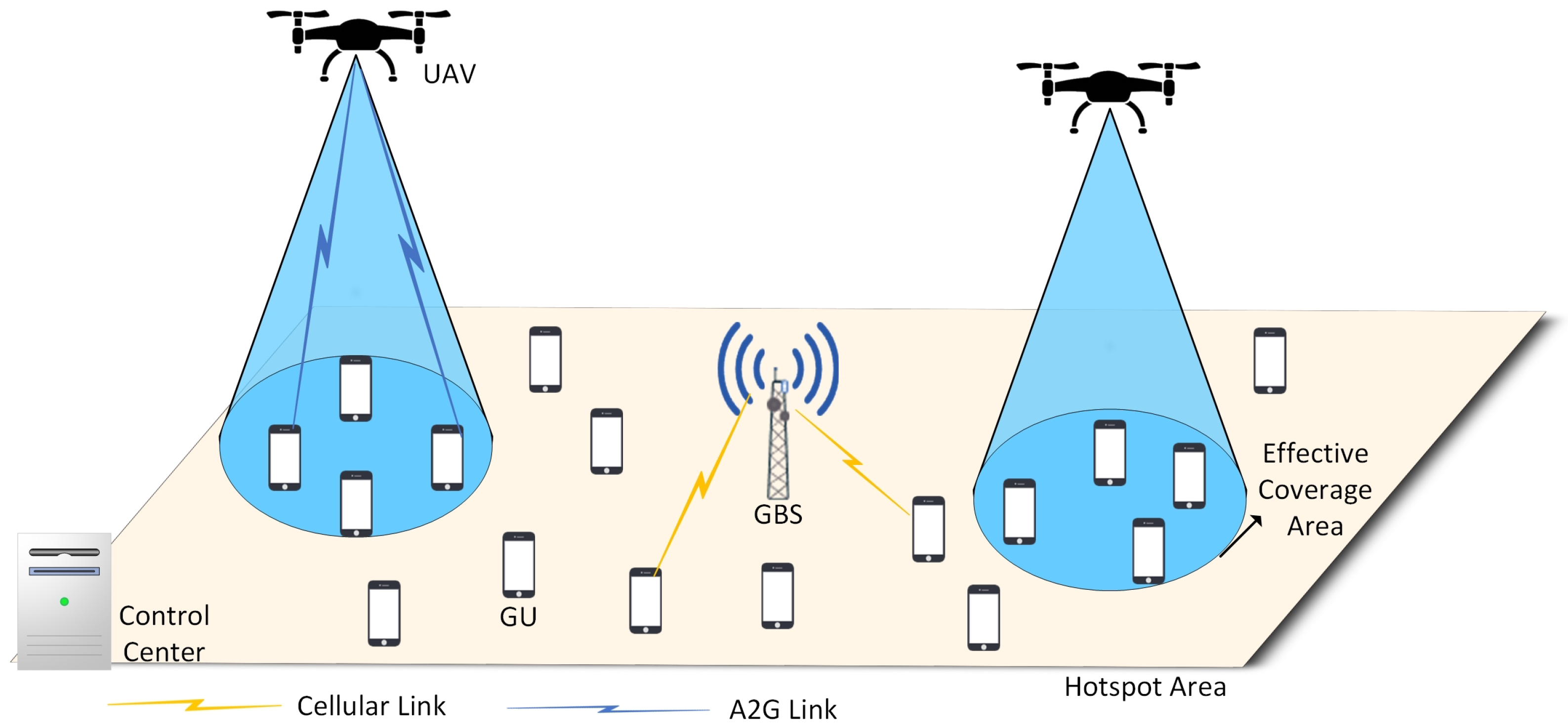
As shown in
Figure 1, we consider a UAV-assisted uplink cellular network in the hotspot area, where a GBS provides communication service to massive ground users (GUs). For simplicity, all GUs are assumed to have homogeneous traffic characteristics with identical QoS demands. To guarantee the QoS of users, multiple UAVs are deployed to offload the traffic of GBSs. We assume that
,
, and
b denote the UAV set, GU set, and GBS, respectively. The 3D positions for UAV
, GU
, and GBS
b are denoted as
,
, and
, where
H and
are the height of each UAV and GBS. Following [
5,
15], we assume that GBSs and the set of UAVs are affiliated to different network operators. Therefore, the GBS and UAV sets use orthogonal frequency bands
and
, respectively. The UAVs share the full bandwidth of
, and the users associated with the same UAV transmit through orthogonal frequency division multiplexing (OFDM).
We assume that the network service period
is divided into
T time-slots with equal duration
, where the time structure is represented by
. The resource scheduling is executed in each time-slot
. Note that the duration of each time-slot is adjustable according to the scheduling unit of network, which can be a single transmission time-slot or consecutive multiple time-slots in a real network. In addition, we assume that the GUs are uniformly distributed in the target area, and the user movement model is established following [
33].
3.2. Communication Model
For the A2G communication link, the 3D distance between GU
k and UAV
n is
The probabilities of having an LoS link and NLoS link between GU
k and UAV
n are calculated as [
34]
and
where
denotes the elevation angle between GU
k and UAV
n, and
a and
b are environment-related constants.
Hence, the path loss between user
k and UAV
n is calculated as
where
is the free space path loss:
where
is the carrier frequency,
c is the speed of light, and
and
are the additional path loss for LoS and NLoS links.
When a user
n is associated to UAV-BS
k, the transmission data rate from GU
k to UAV
n at time-slot
t is denoted as [
10]
where
is the transmit power of GU
k at time-slot
t,
is the channel gain between GU
k and UAV
n at time-slot
t,
is the allocated bandwidth for GU
k, and
is the received noise power density at UAV
n.
For ground communication link, the channel gain between GU
and GBS
b is modeled as [
35]
where
is the distance between GU
k and GBS
b;
is the path-loss exponent for ground links; and
is the fast-fading of ground link
k to
b, which follows Rayleigh distribution.
Therefore, the transmission data rate from GU
k to GBS
b at time-slot
t is denoted as
where
is the transmit power of user
k,
is the channel gain between GU
k and GBS
b at time-slot
t, and
is the allocated bandwidth from GBS
b to GU
k.
3.3. Energy Model
For UAV, the energy consumption comes from communication energy and propulsion energy. The communication energy encompasses the energy used by the communication circuit, signal processing, and signal transmission/reception. For simplicity, we assume that the energy consumption for communication remains constant during each time slot and the on-board energy is fully utilized for UAV’s hover and propulsion [
29]. Following [
7,
36], we model the propulsion energy consumption of UAV
n as a function of the UAV’s flight speed
v:
where
and
are constants of blade profile power and induced power in hovering, respectively.
represents the tip speed of the rotor blade;
is the mean rotor-induced velocity in hover status; and
,
,
s, and
A represent the fuselage drag ratio, air density, rotor solidity, and rotor disc area, respectively. When the UAV hovers at a fixed altitude—that is,
—the energy consumption becomes constant
.
Therefore, the total energy consumption for UAV set
during service period
is calculated as
For GUs, the energy consumption mainly comes from uplink transmission, which can be calculated as
where
denotes the transmit power of GU
k at time-slot
t. For simplicity, we assume that the transmit power of GU remains constant in a time-slot.
3.4. Problem Formulation
In this paper, we aim to minimize the energy consumption of the considered UAV-assisted network with the QoS-guarantee of ground users. Specifically, the objective is to minimize the weighted energy consumption of GUs and UAVs by jointly optimizing the horizontal position of UAVs, ; association between GUs and GBS, ; association between GUs and UAVs, ; bandwidth allocation of GBS, ; bandwidth allocation of UAVs, ; and transmit power of GUs, . is the horizontal position of UAV n at time-slot t, and is the binary variable indicating the association between GUs and UAVs at time-slot t. If GU k is associated to UAV n at time-slot t, ; otherwise, . Similarly, is the association between GUs and the GBS. and are the bandwidth allocated for GU k from GBS b and UAV n at time-slot t, respectively.
The target problem is formulated as follows:
where
and
denote the weight for the energy consumption of GUs and UAVs. Note that constraint C1 indicates that a GU can be associated to only one UAV or GBS. Constraints C2 and C3 represent the bandwidth limit for UAVs, where
and
are the maximum bandwidths of the GBS and UAVs, respectively. Constraint C4 denotes that the transmit power of each GU cannot exceed the maximum power
. Constraint C5 is used to guarantee the QoS of the GUs, where
is the minimum required transmission rate of GUs.
4. Proposed UAV-Assisted Framework
The detailed process of the proposed framework can be seen in
Figure 2. First, the UAVs are deployed using the max-clique algorithm. Next, joint user association, bandwidth allocation, and power control is performed. Finally, the positions of UAVs are updated using the proposed position refinement strategy.
4.1. Initial UAV Deployment
To solve problem , we can observe that constraint C5 determines whether problem has a feasible solution. In other words, if the QoS of all GUs is satisfied, the problem can be solved. This observation inspires us to determine the optimal deployment timing to deploy UAVs. Before the initial deployment of UAVs, the problem should be checked to determine if a feasible solution exists. If a feasible solution exists, there is no need to deploy additional UAV-BSs. Otherwise, a UAV will be added to the network following the deployment strategy presented in this section. Subsequently, the problem will be again checked to determine whether there is a feasible solution. Additional UAVs will be added until can be solved, ensuring that the QoS of all users is satisfied.
Next, we will demonstrate the deployment of UAVs. First, we need to define the effective coverage area for each UAV. Following [
21], we use the free space path-loss threshold
to determine the effective coverage area of the UAV. Specifically, if the free space path loss from GU
k to UAV
n is less than
, GU
k can be covered by UAV
n. From Equation (
5), we can derive the maximum distance
for GU
k to be covered by UAV
n:
Therefore, the effective coverage radius of UAV
n is denoted by
Next, we determine the horizontal positions for the UAVs. Intuitively, UAVs should be deployed in areas with dense user distribution to offload the traffic from ground base stations. Therefore, we use the max-clique algorithm [
8,
14] to identify dense areas within hotspots where UAVs are deployed. The max-clique algorithm is a method used to identify the largest possible subset of nodes in an undirected graph, where each pair of nodes in the subset is directly connected by an edge. In our algorithm, each GU is regarded as a node. An edge exists between two nodes
and
if the following conditions are met:
where
is the horizontal distance between
and
.
After the construction of edges, the user graph
G is formed in the hotspot area. Subsequently, the maximum clique
can be identified and UAVs will be deployed at the centroid of the clique. Specifically, the horizontal position of the UAV
n is expressed as
where
N is the number of nodes in clique
and
is the horizontal position of node
i.
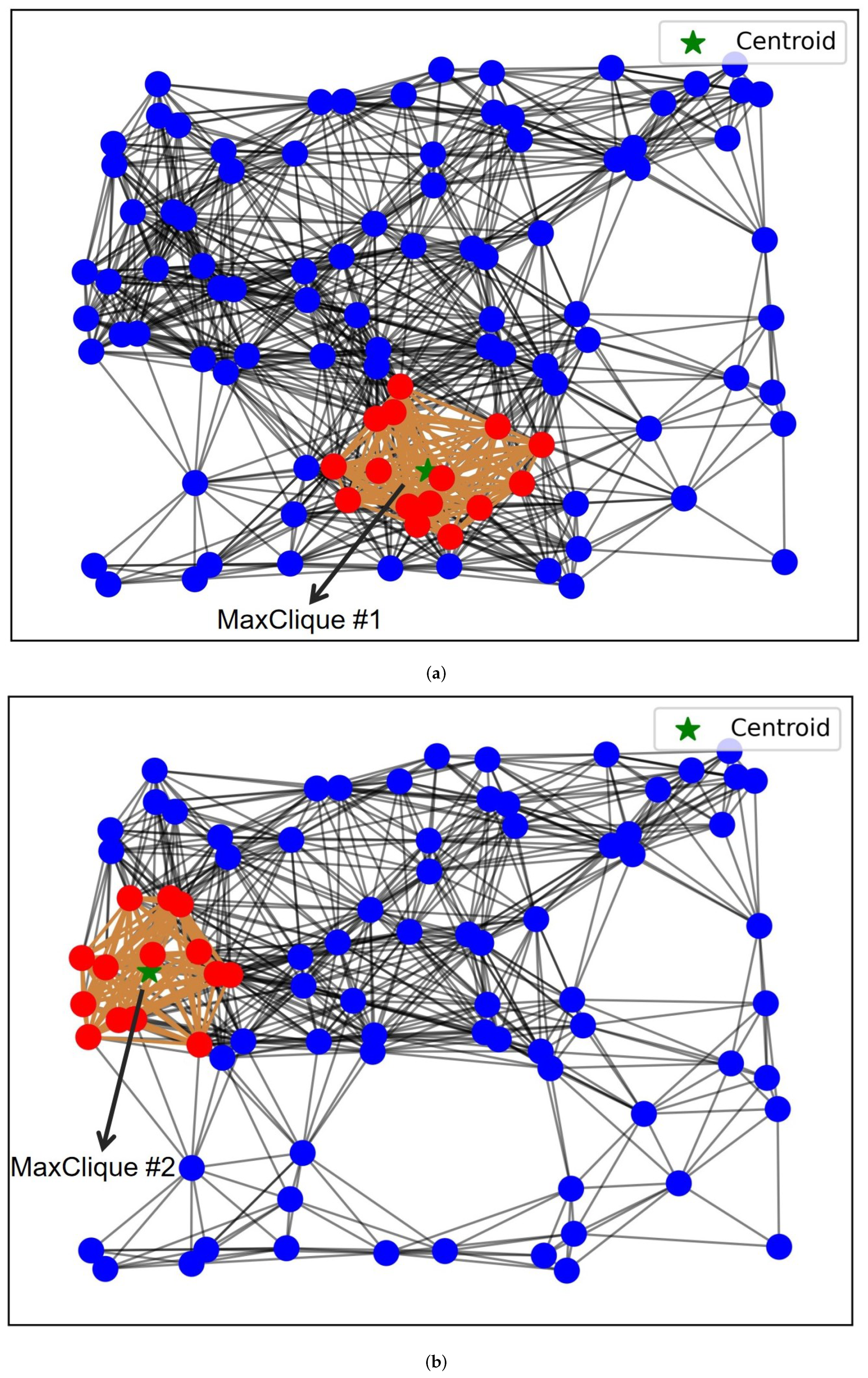
Figure 3 illustrates the process of finding the maximum cliques in the user graph
G. In
Figure 3a, MaxClique
is found, where the nodes and edges are marked in red and orange. The UAV will be deployed at the centroid position, indicated by a green star. If problem
remains unsolved, the UAV deployment process will continue, and the graph will be reconstructed by deleting MaxClique
. MaxClique
will then be found, and a new UAV will be deployed at the centroid position, as shown in
Figure 3b.
The detailed process of UAV deployment using the max-clique algorithm is illustrated in Algorithm 1.
| Algorithm 1 UAV deployment algorithm based on max-clique |
Input: User Graph: G, UAV set: Output: UAV set: , UAV deployment positions: - 1:
while problem does not have a feasible solution do - 2:
Find the maximum clique in G. - 3:
Deploy a UAV n at based on ( 16) and ( 17), add UAV n to . - 4:
Delete from G. - 5:
end while
|
4.2. Energy Consumption Minimization for GUs
After the initial deployment of UAVs, we employ alternative optimization to solve the problem . This problem can be formulated as an optimization task that involves user association, bandwidth allocation, and power control. Specifically, we divide into two sub-problems: (1) Joint optimization of bandwidth allocation and power control under a given user–UAV association scheme. (2) Association optimization under a given bandwidth allocation and power control strategy. The optimal association scheme will be obtained round by round using the coalition game, and the joint optimization of bandwidth allocation and power control will be solved using convex optimization in each round of association optimization.
4.2.1. Joint Optimization of Bandwidth Allocation and Power Control
Given
, the GUs can be divided into multiple groups, where the GUs connected to the same BS are in the same group.
where
is the user group served by UAV
n and
is the user group served by GBS. The cardinality of
and
are denoted as
and
, respectively.
As stated before, there is no interference among different BSs (including UAVs and GBSs) due to frequency orthogonality. In other words, the bandwidth allocation and power control strategy in a BS will not interfere with the transmission rate and energy consumption of other BSs. Therefore,
can be divided into
parallel problems, which can be solved independently. Taking UAV
n as an example: the problem in UAV
n at time-slot
t can be described as
where
is the energy consumption of GUs in UAV
n at time-slot
t,
is the bandwidth allocation strategy of UAV
n at time-slot
t, and
is the bandwidth that UAV
n allocates to user
k at time-slot
t.
is the power strategy of GUs in UAV
n.
To solve problem
, we relax the constraint C5 by approximating
:
Theorem 1. If is a concave function, is also a concave function when .
Then, problem
is a convex optimization problem and can be easily solved by CVX [
38], and the optimal bandwidth allocation
and transmit power
are obtained. Similarly, the joint optimization of bandwidth allocation and power control can be solved for GBS.
4.2.2. User Association
Obviously,
is a mixed integer nonlinear programming (MINLP) problem and is hard to solve. Especially for user association, it is inefficient to traverse every combination of users using exhaustive search. Therefore, we first optimize user association using the coalition game [
39], which can efficiently address optimal decision-making problems and can achieve performance close to exhaustive search (ES).
Intuitively, the users that are only covered by GBSs are restricted to connect to GBSs, and the users under UAV coverage can choose either UAV or GBS. Therefore, we only need to optimize the user association of the users under UAV coverage, which is denoted as a set: .
Therefore, the user association problem is transformed into a coalition game , where is the set of players, is the strategy space, and is the utility set.
Let denote a coalition structure with a cardinality of . denotes the coalitions of players served by the UAV n, which means that the users in connect to the UAV n—that is, . denotes the coalitions of players served by GBS, which means that the users in connect to GBS b, that is, . Note that there is no non-overlap between coalitions , and .
Aiming at reducing the energy consumption of GUs, the utility under structure
is defined as
where
is the optimal solution after solving problem
. It can be seen from (
21) that any coalition formation strategy that fails to guarantee the QoS of GUs will not receive a reward.
Definition 1 (
preference order)
. For GU , the preference order is defined as a complete, reflexive, and transitive binary relation over all the coalitions that k can join. For GU , given two coalition structures and and two coalitions and , denotes that k prefers joining to form structure instead of joining coalition to form structure . In other words, k prefers to connect to rather than from the perspective of reducing energy consumption. The switch rule that determines the preference order for the players is defined asThis switch rule (22) means that GU k prefers joining coalition than joining . Definition 2 (switch operation). Given a coalition structure , if GU k leaves its belonged coalition and switches to coalition , the coalition structure will be updated: .
At the beginning, the coalition structure is formed after each GU connects to its nearest BS. In the following iteration, the algorithm randomly selects a player to perform the switch operation. If the switch rule (
22) is strictly satisfied, the player will leave
and join
. This operation forms a new coalition structure. After multiple rounds of switch operation, the coalition structures are continuously updated and finally converge to the Nash-stable structure, where there is no player who has the motivation to change its association. Hence, the coalition structure is stable and the network utility cannot be improved. The detailed process of joint optimization of bandwidth allocation and power control is shown in Algorithm 2.
| Algorithm 2 Coalition game-based user association for GUs |
- 1:
Initialize after each GU connects to its nearest BS. - 2:
Set current coalition structure . - 3:
while The final Nash-stable coalition structure is not reached do - 4:
randomly select a player and denote its current coalition as . - 5:
k randomly selects another coalition and the temporary coalition structure after k leaves and joins is denoted as: . - 6:
calculate and by solving . - 7:
if then - 8:
k leaves and joins . - 9:
update the coalition structure: . - 10:
else - 11:
k remains in its current coalition . - 12:
end if - 13:
end while - 14:
Output The optimal user association strategy and .
|
4.3. Position Refinement for UAVs
Taking into account user mobility, fine-tuning of the UAV’s position is required to adjust to the new distribution of users and save the transmit power of users. However, the movement of UAVs also consumes energy. To achieve the trade-off between saving the energy consumption of GUs and not increasing the propulsion energy of UAVs, we aim to optimize the weighted energy consumption of GUs and UAVs. Following the same assumption of [
19], the flight area of the UAVs is divided into multiple grids. The candidate positions for UAV are confined in a 2D grid world with grid spacing
.
According to [
40], the user association interval (UAI) is larger than the position refinement interval (PRI). Therefore, position refinement is performed under a fixed user association strategy and the movement strategy of a UAV does not impact the energy consumption of other UAVs. For each UAV, the optimal movement strategy can be learned independently, which is modeled as an MDP model [
41]. During each PRI, the UAVs are regarded agents and interact with the environment. Each UAV
learns the optimal movement strategy during the offline training stage to minimize the energy consumption of the UAV
n and its associated GUs
. Formally, MDP can be formulated as a five-tuple
, where
is the state space,
is the action space,
is the position fine-tuning strategy,
is the reward space,
p is the state transition probability distribution, and
is the probability that the agent receives a reward
and the system transits to state
after the agent executes
according to current state
.
As mentioned above, each agent learns the optimal position refinement strategy independently without affecting others. The training process for each agent is completed offline and the optimal strategy is obtained. During the execution stage, each agent perceives the current state and executes actions based on . Next, we define the state space, the action space, and the reward function for each agent n.
4.3.1. State Set
The state space of each agent
n is defined as
where
is the horizontal positions of UAV
n at time step
t and
is the centroid position of GUs associated with UAV
n.
4.3.2. Action Set
The candidate actions for each agent
n are five moving directions, including moving forward, flying backward, turning left, turning right, and hovering stationary. Therefore, the action
of agent
n is selected from the action set, which is defined as
After executing the action, the agent will move to the nearest grid in the corresponding direction.
4.3.3. Reward Function
The objective of our algorithm is to minimize the weighted energy consumption of UAVs and GUs during each PRI. Therefore, the reward function designed for each UAV is related to the energy consumption of the UAV and its associated GUs. After the agent executes action
at state
, the reward
is defined as
where
is the energy consumption of GUs at step
t and
is the optimal solution of problem
after updating the position of UAV
n.
is the energy consumption of the UAV
n during the execution of
:
Note that when the agent hovers stationary, the velocity
and the
in (
9) can be simplified to
.
In this paper, we adopt the double deep Q-network (DDQN) to solve the position refinement problem for UAVs.
Figure 4 shows the framework of proposed DDQN algorithm. Unlike the deep Q-Network (DQN), DDQN utilizes two deep neural networks known as the online network and the target network. The online network is responsible for the selection of actions and the estimation of the state action value function (Q-values). During the training phase, the online network selects an action based on the current state and estimates the state–action value function. The parameters of the online network are updated repeatedly to improve its estimation of the Q-value function. On the other hand, the target network is used to estimate the target Q-values, which are used to update the parameters of the online network. The parameters of the target network are periodically copied from the online network. The main function of the target network is to stabilize the training process, reduce variance in the estimation of the target Q-values, and improve the convergence speed of the algorithm.
At each step t of the training process, each agent observes its local state and executes an action according to -greedy policy. After the execution of , the system transits to new state and feeds back reward to the agent. The tuple is stored in the experience replay buffer.
A batch of experience tuples
are sampled from the experience replay buffer, where
B is the size of
. The target network is used to calculate the target Q-value of sample
i:
where
and
are the parameters of the online and target networks;
is the discount factor; and
and
represent the output of the online network and target network, respectively.
Then, the loss function for the online network is defined using
The parameter
of the online network is updated using gradient descent:
The parameters
of the target network are periodically soft-updated using the parameters
of the online network.
where
is the soft updating rate. The detailed process of DDQN-based position refinement algorithm for each UAV is presented in Algorithm 4.
4.4. Overall Algorithm Design
In Algorithm 3, we illustrate the overall procedure of the proposed UAV-assisted energy consumption minimization algorithm. At first, UAVs are deployed based on Algorithm 1. After that, the optimal movement strategies are learned by UAVs by executing Algorithm 4. In the following, the GUs report their positions at each time-slot. When the user association interval is reached, the association between GUs and UAVs (or BSs) is constructed by executing Algorithm 4. Finally, during each position refinement interval, the position of each UAV is fine-tuned using the learned movement strategy
. The DDQN algorithm in Algorithm 3 is designed for offline training handled by the centralized server. During the execution of Algorithm 3, UAVs only require lightweight inference, which is feasible for edge devices. The complexity of the neural network ensures real-time decision-making on UAVs with standard onboard processors. Training time is acceptable for pre-deployment optimization.
| Algorithm 3 Overall procedure of proposed algorithm |
- 1:
Input: original position of UAVs , GBS and GUs, state space ,action set - 2:
Output: optimal strategy for UAVs’ position refinement , user association and , bandwidth allocation and , power control . - 3:
Initial deployment of UAV: - 4:
Deploy UAVs according to Algorithm 1. - 5:
Offline training: - 6:
Run Algorithm 4, obtain the optimal movement strategy for each UAV n. - 7:
for
do - 8:
Each GU reports its current position to the control center. - 9:
User association: - 10:
if then - 11:
Run Algorithm 2 to re-construct the user-BS association (, ), and then obtain the optimal bandwidth allocation (, ) and power control . - 12:
end if - 13:
Position refinement for UAV: - 14:
if then - 15:
Each UAV executes the movement action following policy . - 16:
end if - 17:
end for
|
| Algorithm 4 DDQN-based position refinement algorithm for each UAV |
- 1:
Initialize the online network parameters and the target network parameters . - 2:
Initialize the parameters: , , , B. - 3:
for each training episode t do - 4:
Observe the current state . - 5:
Execute the action according to policy . - 6:
Calculate the optimal solution of and obtain the reward ; the system transits to the next state . - 7:
Store the tuple to the replay buffer. - 8:
Sample the mini-batch set from the replay buffer. - 9:
Calculate the target Q-values of the samples in using ( 12). - 10:
Update the parameters of online network using ( 29). - 11:
if network update interval is reached then - 12:
Update . - 13:
end if - 14:
end for
|
5. Simulation Results
The considered hotspot area is a 1000 m × 1000 m rectangular area, where massive GUs are uniformly distributed in the area. The height of each UAV is fixed at 200 m and the path-loss threshold to ensure the coverage is
dB [
21]. The flight velocity
v for each UAV is set to 10 m/s, and the flight parameters are as follows [
36]:
w,
w,
m/s,
m/s,
,
kg/m
3,
, and
m
2. The user association interval
and position refinement interval
are 100 s and 10 s, i.e., each
consists of 10
. The deep neural network in our DDQN algorithm comprises an input layer, two fully connected hidden layers with 128 and 64 neurons, and an output layer. The rectified linear unit (ReLU) is adopted as the activation function, and the Adam optimizer is used to update the network parameters. The learning rate, discount rate, and soft updating rate are configured as follows:
,
,
. The size of the mini-batch is 256, and the target network update interval is five steps. The energy consumption weights of the GUs and UAVs are
and
. The detailed simulation parameters are shown in
Table 1.
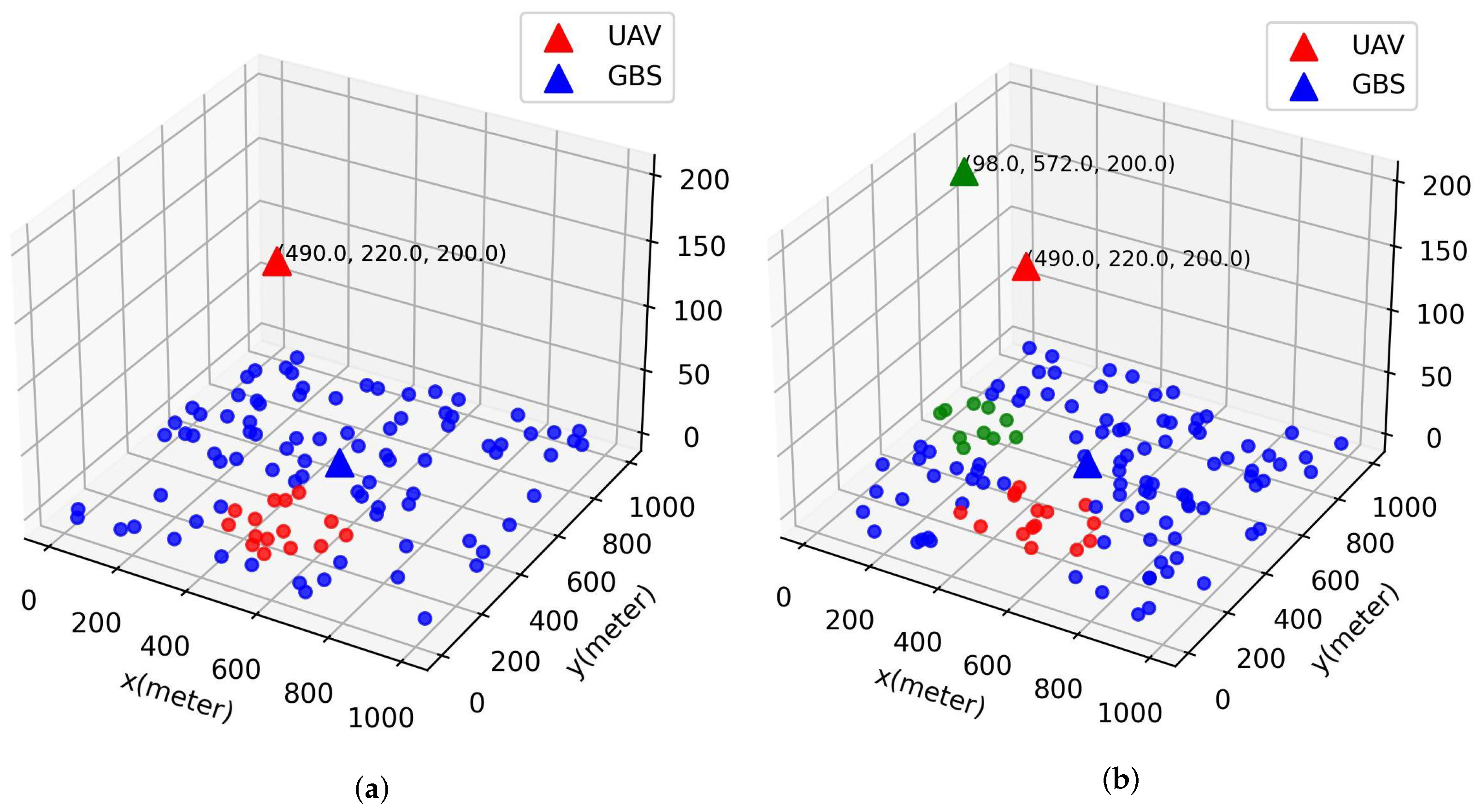
In
Figure 5a,b, we plot the 3D deployment of UAVs and locations of GUs. The GUs and their associated UAV are plotted using the same color. In
Figure 5a, the number of GUs
K is 100 and only one UAV is deployed, which means that the QoS of GUs can be satisfied under power and bandwidth constraints. However, as
K increases from 100 to 120, another UAV needs to be deployed to ensure that the QoS of all users can be satisfied in the current network.
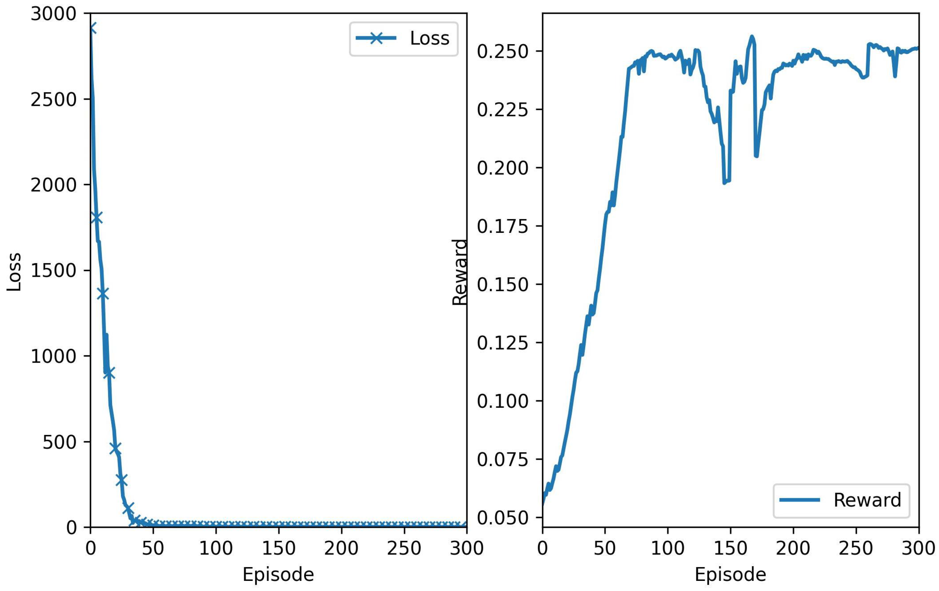
Figure 6 shows the convergence performance with the training episodes of the proposed DDQN algorithm, where each episode consists of 100 training steps. As shown in
Figure 6a, the training loss tends to decrease rapidly after the training starts. At about 60 episodes, it drops to below
, indicating that the online network in the proposed DDQN algorithm has good performance to generate Q-values for state–action pairs.
Figure 6b shows the change of reward of each episode, where the reward grows rapidly at the beginning and then the growth rate tends to slow. Finally, the accumulated reward converges, which indicates that the agent has learned the optimal movement strategy.
To validate the effectiveness of the proposed algorithm in terms of saving energy, we compare the performance of the proposed algorithm with the following benchmark schemes:
Random UAV deployment (RUD): the UAVs are randomly deployed in the hotspot area.
Static UAV deployment (SUD): the UAVs are deployed using the max-clique algorithm proposed in
Section 4.1; however, the positions of UAVs will not be refined with the movement of GUs.
Centroid-based UAV movement (CUM): different from the proposed DDQN algorithm, the UAVs under the CUM strategy change their positions to the centroid of associated GUs in each PRI.
Multi-agent DRL-based distributed UAV-BS control approach (MAUC) [
42]: this method employs a distributed multi-agent DRL framework to optimize UAV trajectories, with a primary objective of weighted-throughput maximization.
Dueling deep Q-Learning (DDQL) [
43]: this DRL-based scheme is designed to obtain the optimal trajectory and system throughput.
Note that all the above algorithms employ the same user association, power control, and bandwidth allocation strategies with the proposed algorithm.
Figure 7 plots the UAV trajectory for the proposed DDQN-based UAV position refinement strategy and the centroid-based UAV movement (CUM) strategy. In two deployment scenarios with one UAV and two UAVs, the travel distance of UAVs in the proposed algorithm is significantly shorter than that of CUM. This is because UAVs under the CUM strategy continuously move with the centroid position of users. However, in the DDQN-based algorithm, the learned movement strategy observes the user distribution and adaptively selects actions for UAVs based on the current state. The UAVs choose to remain stationary unless the learned movement strategy indicates that changing position will result in higher reward. Therefore, the movement actions selected for the UAVs under the proposed algorithm are more efficient and energy-efficient. This conclusion is further supported by the figures below.
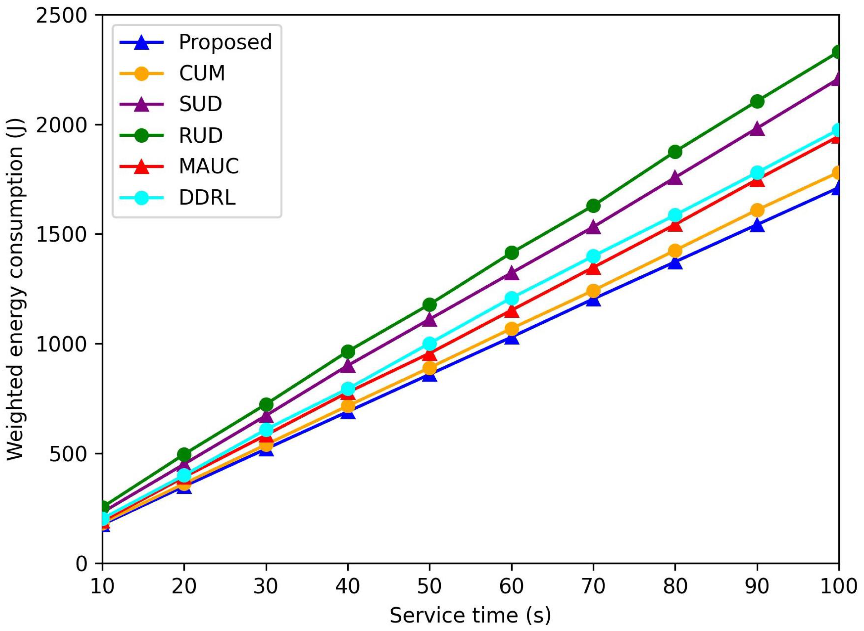
Figure 8 shows the change in weighted power consumption over a network service period of 100 s. Initially, the energy consumption of the proposed algorithms—RUD, SUD, and CUM—is nearly identical. However, as users move, the proposed algorithm achieves the lowest energy consumption among all schemes. The two static UAV deployment schemes, RUD and SUD, are unable to adjust the positions of UAVs, leading to increased energy consumption for GUs. In contrast, the proposed algorithm dynamically adjusts UAV positions, achieving a balance between reducing GU transmit power and avoiding excessively increased UAV propulsion energy by exploiting the DDQN-based position refinement algorithm. In comparison, the CUM strategy consumes more energy than the proposed algorithm due to frequent position changes. The benchmark schemes proposed in [
42,
43] mainly focus on maximizing system capacity, which inherently limits their ability to achieve energy savings.
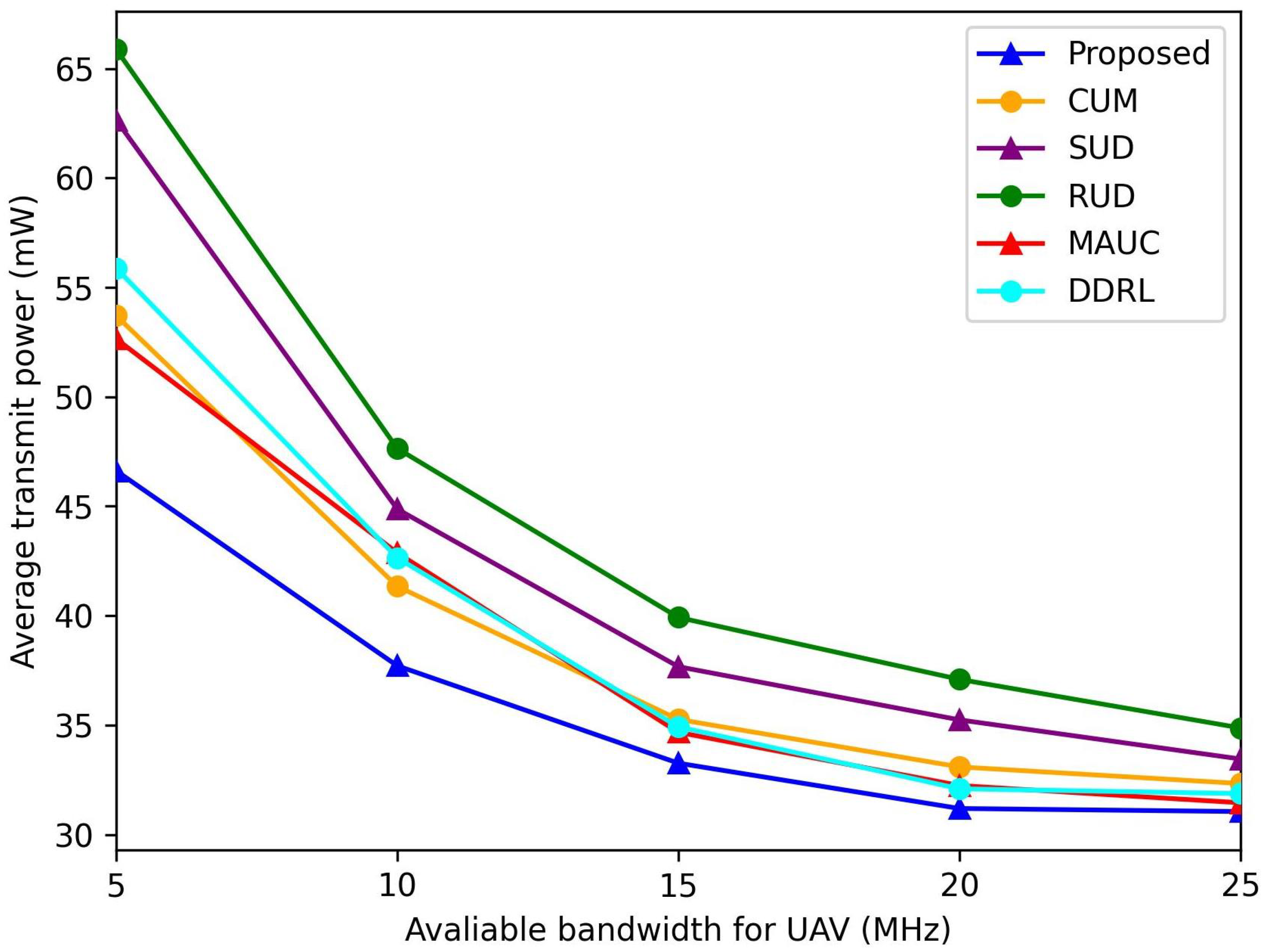
In
Figure 9, we show the effect of the bandwidth
on the average transmit power of GUs
. It can be seen that the
under all the schemes decreases with the increase in available bandwidth
of each UAV. When bandwidth resources are limited (
MHz), the average transmit power of GUs increases because GUs need to increase their transmit power to meet
under an insufficient allocated bandwidth. When bandwidth resources are sufficient (
MHz), the discrepancy in average transmit power between the proposed algorithm and the benchmark schemes narrows significantly. This reduction in power gap can be attributed to increased flexibility in resource allocation under abundant bandwidth conditions, allowing both approaches to operate closer to their optimal performance levels. However, the proposed algorithm maintains its superior energy efficiency by intelligently managing power consumption without compromising system performance.
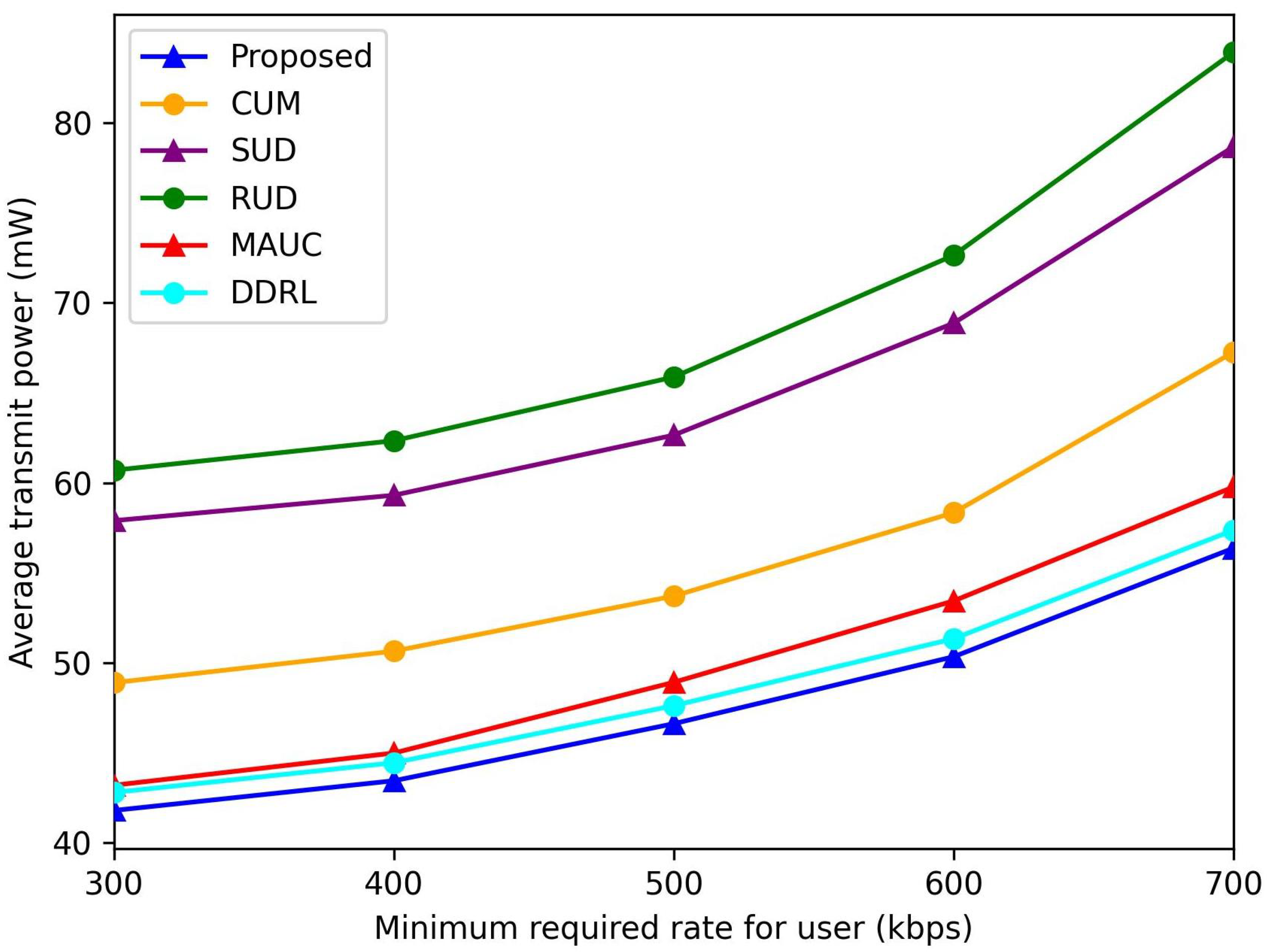
Figure 10 illustrates the total transmission power of all GUs under different schemes as the required transmission rate
varies. As
increases, each GU must increase its transmit power to meet the rate requirement under limited bandwidth constraints. However, utilizing the proposed algorithm, GUs consistently achieve the desired transmission rate with significantly lower transmit power compared to the benchmark schemes. This efficiency stems from the algorithm’s optimized resource allocation and energy-aware design, which minimize power consumption while ensuring that performance targets are met.
6. Conclusions
In this paper, we investigate a UAV-assisted air-to-ground network in hotspot areas, addressing the critical challenge of joint UAV deployment, user association, power control, and bandwidth allocation under power and QoS constraints. The proposed three-phase framework uniquely integrates coalition game theory for stable user–UAV associations and a DDQN algorithm for adaptive UAV trajectory refinement, enabling real-time responsiveness to user mobility. The proposed DDQN-based algorithm reduces total energy consumption compared to benchmark schemes, primarily by reducing the distance traveled by a UAV while maintaining QoS. This is achieved through a mobility-aware state space design that dynamically tracks user centroid shifts, ensuring robust performance even with fluctuating GU densities. Comparative experiments demonstrate that the proposed DDQN algorithm achieves lower energy consumption.
This study bridges the gap between theoretical optimization and practical UAV deployment strategies, offering a scalable blueprint for energy-efficient aerial networks in dynamic environments. The framework is deployable in real-world scenarios, such as disaster response or IoT-enabled smart cities, where rapid user redistribution is common. The limitations of this paper include the assumption of homogeneous QoS requirements, which will be extended to multi-class traffic (e.g., mixed video/voice/data) in future work. Furthermore, while the current model focuses on 2D user mobility, extending to 3D UAV deployment in urban canyons presents an open challenge. These enhancements will form our next research phase.


