Article

IVU-AutoNav: Integrated Visual and UWB Framework for Autonomous Navigation

1
College of Aeronautics, Northwestern Polytechnical University, Xi’an 710072, China
2
National Key Laboratory of Aircraft Configuration Design, Northwestern Polytechnical University, Xi’an 710072, China
3
Chengdu Aircraft Design & Research Institute, Aviation Industry Corporation of China (AVIC), Chengdu 610091, China
*
Author to whom correspondence should be addressed.
These authors contributed equally to this work.
Drones 2025, 9(3), 162; https://doi.org/10.3390/drones9030162
Submission received: 19 December 2024 / Revised: 16 February 2025 / Accepted: 21 February 2025 / Published: 22 February 2025
(This article belongs to the Special Issue Drones Navigation and Orientation)

Abstract

:
To address the inherent scale ambiguity and positioning drift in monocular visual Simultaneous Localization and Mapping (SLAM), this paper proposes a novel localization method that integrates monocular visual SLAM with Ultra-Wideband (UWB) ranging information. This method enables high-precision localization for unmanned aerial vehicles (UAVs) in complex environments without global navigation information. The proposed framework, IVU-AutoNav, relies solely on distance measurements between a fixed UWB anchor and the UAV’s UWB device. Initially, it jointly solves for the position of the UWB anchor and the scale factor of the SLAM system using the scale-ambiguous SLAM data and ranging information. Subsequently, a pose optimization equation is formulated, which integrates visual reprojection errors and ranging errors, to achieve precise localization with a metric scale. Furthermore, a global optimization process is applied to enhance the global consistency of the localization map and optimize the positions of the UWB anchors and scale factor. The proposed approach is validated through both simulation and experimental studies, demonstrating its effectiveness. Experimental results show a scale error of less than 1.8% and a root mean square error of 0.23 m, outperforming existing state-of-the-art visual SLAM systems. These findings underscore the potential and efficacy of the monocular visual-UWB coupled SLAM method in advancing UAV navigation and localization capabilities.

1. Introduction

In environments where Global Navigation Satellite System (GNSS) signals are not available or obstructed, autonomous localization becomes the cornerstone for the reliable operation of unmanned aerial vehicles (UAVs) [1,2,3]. Real-time Simultaneous Localization and Mapping (SLAM) technology [4,5,6], known for its independence from external devices and robust adaptability to diverse scenarios, has emerged as the primary technical solution for current UAV autonomous navigation. Taking into account factors like energy efficiency, processing capabilities, and the physical configuration of UAVs, monocular vision SLAM has emerged as the favored solution for autonomous navigation [7].
Although visual SLAM can estimate position and create environment map simultaneously, it has problems of scale ambiguity and positional drift issues as flight distance increases. Monocular visual SLAM relies solely on 2D images captured by a monocular camera. Moreover, while the relative motion of objects within the scene can be estimated through the camera’s movement, the depth information of environmental objects cannot be obtained, resulting in scale uncertainty in pose estimation. Additionally, as the camera moves, errors in feature matching and tracking accumulate, and the loss of feature points further exacerbates the issue, causing SLAM localization to drift with increasing distance.
To address the scale ambiguity problem, there are three primary methods:
  • The first method involves calibrating the camera to the ground plane height or storing the geometric dimensions of typical landmarks in the working environment [8]. By calculating the ratio between the ground plane height or landmark size in the SLAM system and the ground truth, the scale of the SLAM system can be restored. Nonetheless, this approach requires a high degree of distinctiveness in camera placement and environmental features, which poses difficulties in adapting to more intricate settings.
  • The second method includes obtaining an accurate scale by adding sensors directly, e.g., by using stereo or multi-camera systems with a fixed baseline to accurately measure environmental depth through triangulation, or by employing devices such as an Inertial Measurement Unit (IMU) [9,10] or LiDAR [11,12,13] rangefinders to collect precise scale information. However, these methods require additional sensor installation;
  • The third method involves utilizing machine learning algorithms. By identifying common standard landmarks like pedestrians or vehicles in the images captured by the camera and combining them with prior information on the average geometric dimensions of these landmarks, the scale of the SLAM system can be accurately determined. However, this method requires high-performance computing platforms, imposing high demands on the computational power and power consumption of the onboard computing platform [14,15].
The visual SLAM method achieves autonomous localization by continuously estimating the camera pose and map point positions. As the distance traveled increases, errors in the estimated map points or camera poses propagate and accumulate over subsequent states, leading to a drift in the localization information. Current mainstream visual SLAM systems utilize techniques such as the bag-of-words model or building a database to detect whether the images captured by the camera form loops with historical images [16,17]. By solving for the similar transformation between loop-closing frames, these systems correct the drift in the SLAM system. Multi-sensor fusion SLAM integrates global positioning information from tightly coupled GNSS or Ultra-Wideband (UWB) communication to eliminate local accumulation errors in visual positioning [18]. However, these methods require the presence of loops in the UAV’s flight trajectory or the addition of extra global positioning devices, which limits the adaptability of UAVs to various mission scenarios.
UWB equipment calculates the distance between devices by measuring the flight time or signal attenuation of the signals sent and received between them. To achieve three-dimensional positioning of objects, at least four non-coplanar UWB positioning anchors must be installed in the working environment, and their positions must be calibrated. By solving the geometric relationships between the distances from the object to these anchors, three-dimensional positioning can be achieved [19]. However, deploying this solution becomes challenging in large work areas with complex terrain for UAV applications, as it is difficult to install fixed anchors and accurately calibrate them.
In the research of visual fusion with UWB positioning [20,21,22,23,24], integrating visual information with UWB technology effectively overcomes the limitations of a single positioning system, enhancing positioning accuracy and stability. UWB provides real-time ranging, which allows for the recovery of the scale for visual localization systems, and ranging data can further constrain the UAV’s trajectory, mitigating the positioning drift. Unlike traditional systems, the visual localization system operates independently of the sensor’s installation position as it adapts to the UAV’s motion. This integrated approach, leveraging data from multiple sensors, offers a more reliable solution for UAV navigation in complex environments. By fusing visual data with UWB technology, the UAV can more accurately perceive its relative distances and surrounding environment, achieving precise localization and thereby enhancing its autonomous flight capabilities and safety.
These methods integrate UWB positioning information with visual or visual–inertial positioning information to address the scale issue in visual SLAM and enhance positioning accuracy. However, these methods do not account for UWB signal obstructions, and they do not utilize UWB distance measurements in the estimation of poses from image frames, leading to notable positioning errors.
Although the above-mentioned method offers several advantages, its practical application is still challenged by the intricacies involved in the setup and alignment of UWB anchors. In order to address the limitations of existing solutions, this paper introduces a novel UAV positioning framework, the Integrated Visual and UWB Framework (IVU-AutoNav), which tightly integrates UWB distance measurements with monocular visual SLAM. Unlike previous methods that necessitate multiple calibrated UWB anchors or additional sensors, IVU-AutoNav employs a single unidentified UWB anchor to dynamically estimate its position within the SLAM framework. This innovative approach not only eliminates the need for complex anchor calibration but also offers a lightweight and computationally efficient solution for real-time UAV navigation.
The proposed method marks a significant theoretical advancement in the integration of visual SLAM and UWB technologies. By strategically placing a single UWB anchor within the operational environment, our method dynamically estimates the anchor’s position using a novel optimization framework. This approach eliminates the need for complex calibration procedures, reduces system complexity, and enhances the navigation system’s adaptability to dynamic environments. The core innovation of our method is the seamless integration of visual and UWB data within a factor graph optimization framework. Unlike traditional methods that depend on multiple pre-calibrated anchors or additional sensors, our framework leverages the complementary strengths of visual SLAM and UWB ranging to achieve high-precision localization. The dynamic estimation of the UWB anchor’s position and the continuous optimization of the factor graph ensure that our method maintains high accuracy and robustness, even in challenging scenarios.
This choice is driven by the dual goals of minimizing setup complexity and maximizing localization accuracy. Unlike traditional methods that necessitate multiple pre-calibrated UWB anchors, our method can automatically estimate the UWB anchor’s location within the SLAM framework. This innovation not only eliminates the need for complex anchor calibration but also reduces overall system complexity and deployment time. By tightly integrating UWB distance measurements with monocular visual SLAM, our method effectively mitigates the scale ambiguity and localization drift issues often encountered in monocular SLAM systems. Furthermore, the incorporation of a well-designed motion model effectively filters out erroneous measurements caused by obstructions in the UWB signal path. The seamless integration of UWB and visual tightly coupled SLAM techniques not only enhances the precision and robustness of autonomous UAV positioning but also paves the way for improved performance in challenging real-world scenarios. This method represents a significant advancement in the field of UAV localization and demonstrates great potential for overcoming the limitations of traditional monocular visual SLAM approaches.
The remainder of this paper is organized as follows: Section 2 presents the methodology of the proposed IVU-AutoNav framework, detailing the integration of monocular visual SLAM and UWB ranging. Section 3 shows the experimental setup and results, demonstrating the effectiveness of the proposed method through both simulation and real-world tests. Section 4 discusses the implications of the results and outlines potential future research directions. Finally, Section 5 concludes this paper by summarizing the key contributions and findings.

2. Related Work

Autonomous localization is crucial for UAVs operating in environments where GNSS signals are obstructed. SLAM technology has emerged as a key solution for UAV autonomous navigation due to its independence from external devices and adaptability to diverse scenarios. UWB can directly provide distance measurement which can greatly improve the localization accuracy. Furthermore, combined with SLAM, performance can be further improved. Some related methods are discussed and analyzed further below.

2.1. Visual SLAM Localization

Visual SLAM systems typically rely on feature extraction and matching to estimate camera motion and build a map of the environment. Notable systems include ORB-SLAM3 [4], which extends previous versions by supporting monocular, stereo, and RGB-D inputs, offering improved performance in dynamic environments [4]. This system is praised for its versatility but still faces challenges related to scale ambiguity and drift over time. Direct methods like LSD-SLAM [5] use image intensity values directly, allowing for more accurate map reconstruction in some scenarios. However, these methods can be computationally intensive and are sensitive to lighting changes. These methods [25,26,27,28,29] show promise in enhancing robustness but often require extensive training data and may struggle in real-time applications. Key challenges in visual SLAM include dealing with dynamic environments, improving real-time performance, and reducing computational demands. Recent studies aim to address these issues by integrating additional sensors and leveraging machine learning techniques.

2.2. UWB Localization

UWB technology, used for three-dimensional positioning by measuring signal flight time or attenuation, requires multiple non-coplanar anchors for accurate calibration. Recent advancements have tightly coupled UWB distance measurements with visual or inertial SLAM techniques to enhance positioning accuracy and address scale issues. However, these methods may not consider UWB signal obstructions, leading to significant positioning errors. UWB localization systems utilize Time of Arrival (ToA) or Time Difference of Arrival (TDoA) methods to calculate distances between UWB tags and anchors. These systems are highly effective in environments where GNSS is unavailable or unreliable, such as indoors or in urban canyons [20]. Recent advancements focus on mitigating the effects of multipath interference and obstructions, which can degrade UWB performance. Techniques such as machine learning-based multipath mitigation [21] and hybrid systems combining UWB with other sensors [22] have shown promise in addressing these challenges. Despite its advantages [30], UWB localization can be affected by environmental factors and requires a dense network of anchors for optimal performance. Research continues to enhance UWB’s robustness and reduce its deployment costs.

2.3. UWB-Integrated Visual SLAM Localization

In the realm of visual fusion with UWB positioning, integrating visual data with UWB technology has shown promise in enhancing positioning accuracy and stability for UAVs. This fusion approach leverages multiple sensor data to provide a more reliable solution for UAV navigation in complex environments, enabling precise positioning and enhancing autonomous flight capabilities and safety. Traditional methods that combine visual SLAM with UWB positioning information typically rely on loosely coupling the UAV’s position, determined by multiple anchor points, with the visual SLAM data. These methods commonly employ Kalman filtering to estimate the UAV’s position, but they require the UWB positioning system to be fixed, thereby limiting the UAV’s operational range. In contrast, this paper proposes a method in which a single UWB anchor’s position is estimated through the visual localization system, and UWB ranging data are tightly integrated with the visual image data. This approach overcomes the limitation imposed by the number and position of UWB anchors on the UAV’s operational range. By analyzing the distance variations between the visual localization trajectory and the UWB anchor, this method addresses the scale ambiguity issue in the visual system and corrects trajectory drift, thereby improving the accuracy and stability of the localization process.
Recent research focuses on fusing UWB and visual data to improve robustness in dynamic and GNSS-denied environments. For example, Lin et al. [17] propose a system that combines UWB and visual SLAM to enhance UAV localization, demonstrating improved accuracy and stability in complex scenarios. Nguyen et al. [23] propose a tightly coupled odometry framework, which combines monocular visual feature observations with distance measurements provided by a single UWB anchor with an initial guess for its location. VIR-SLAM [24] propose a system combining UWB ranging with VIO to reduce the drift in challenging environments. Using static anchors and inter-robot ranging, it enables collaborative SLAM with efficient map fusion. Thien et al. [31] have shifted the focus towards the use of UWB measurements in a “range-focused” manner, by leveraging the propagated information available from the visual–inertial odometry (VIO) pipeline. This perspective enables UWB data to be utilized more effectively, as it addresses the time-offset of each range measurement and ensures that all available measurements can be incorporated into the system. Such strategies highlight the potential of integrating UWB with visual–inertial systems to enhance the overall performance and accuracy of localization techniques. UVIO [32] performs attitude estimation on the distance UWB estimates using adaptive Kalman filtering, and establishes a new noise covariance matrix based on the Received Signal Strength Indicator (RSSI) and the Estimation of Precision (EOP) to reduce the impact of Non-Line-of-Sight (NLOS) conditions. Subsequently, the corrected UWB estimates are tightly integrated with the IMU and visual SLAM through Factor Graph Optimization (FGO), further refining the attitude estimation. Hybrid systems leverage UWB’s precise ranging capabilities with visual SLAM’s mapping strengths, resulting in improved localization performance. These systems are particularly beneficial in environments with visual occlusions or poor lighting conditions, where visual SLAM alone may struggle. Challenges in integrating UWB with visual SLAM include managing the computational complexity of data fusion and ensuring real-time performance. Research continues to explore efficient algorithms and sensor fusion techniques to address these issues.
In conclusion, the integration of UWB distance measurements with monocular visual SLAM holds promise for overcoming challenges related to scale ambiguity and localization drift. This paper introduces a novel UAV positioning methodology that tightly integrates UWB distance measurements with monocular visual SLAM, thereby enhancing the precision and robustness of autonomous UAV positioning. By strategically placing a single UWB anchor and integrating visual and distance data, this approach not only improves performance in challenging real-world scenarios but also signifies a significant advancement in UAV localization research.

3. Methodology

The Methodology Section is divided into five parts. First, we provide an overview of the entire framework. Then, we detail the four main components of the framework in separate subsections.

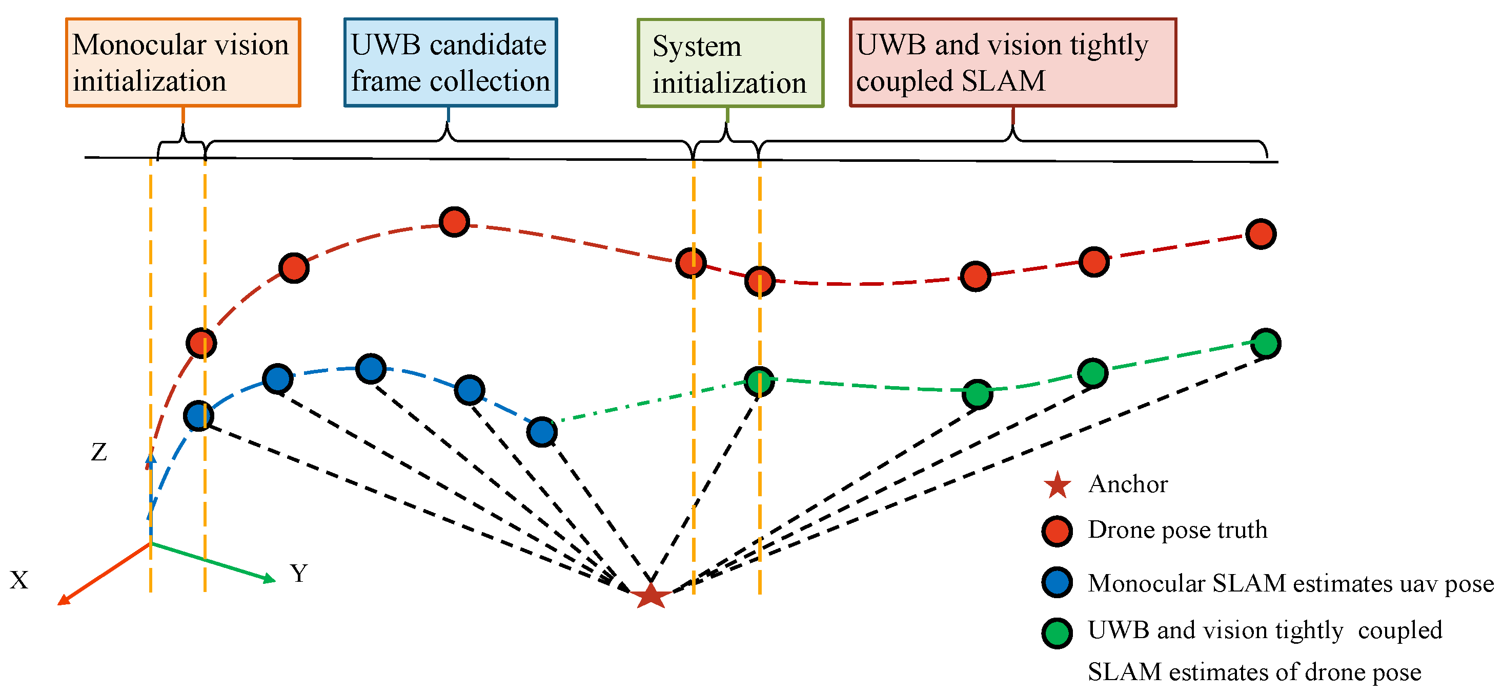
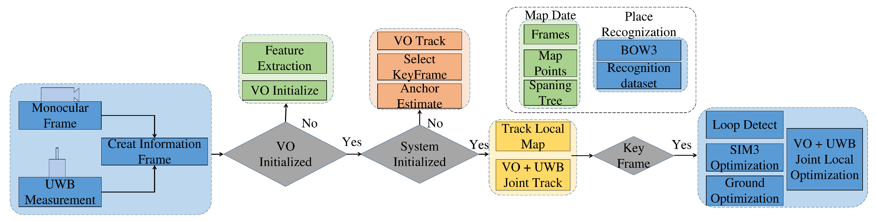
3.1. Problem Statement and Method Overview

In order to address the scale ambiguity and localization drift issues in monocular visual SLAM and enhance real-time positioning accuracy for UAVs, this paper introduces a tightly coupled SLAM system that integrates distance measurements with visual information. The system process, as illustrated in Figure 1, can be divided into four distinct phases: visual initialization, UWB candidate frame collection, system initialization, and tightly coupled UWB and visual SLAM. The architecture of proposed integrated visual and UWB framework is illustrated in Figure 2. We have compiled all the symbols used in the equations into a table and provided explanations for each mathematical symbol, as shown in Table 1.
In the first phase, the monocular visual SLAM initialization is executed. This involves initializing consecutive pairs of images captured by the camera, calculating the homography and essential matrices between the two frames to determine the rotation and translation relationships. Through cross-validation using feature point pairs, the pose transformation between the two frames is obtained, and the positions of corresponding map points are determined through triangulation.
The second phase includes the execution of the UWB candidate frame selection algorithm. Here, the UWB distance measurements, after excluding erroneous data points, are temporally aligned with image frames. Information frames are created by combining image and distance information, and frames with positional differences exceeding a predefined threshold from the previous UWB candidate frame are selected and stored in the candidate frame set.
In the third phase, the system initialization algorithm is executed. By evaluating the reprojection errors of feature points in the candidate frame set and their corresponding map points, an optimization equation is formulated to globally optimize the poses of the candidate frames. Additionally, an optimization equation for determining the anchor position is established based on the distance errors between the information frames and the anchor. In this study, the information frame refers to the frame which contains visual images and UWB distance measurements. By solving optimization equations, the anchor position and the system scale factor can be estimated.
The fourth phase involves the execution of a tightly coupled SLAM algorithm that integrates UWB and visual information. For new information frames placed into the system, feature point matching and reprojection error calculations are performed. Utilizing the anchor position and measured distances, distance errors between the current information frame and the anchor are established. By leveraging the reprojection errors and distance errors of the current frame, a pose graph optimization model is constructed to determine the pose of the current frame. Unmatched feature points between the current frame and the previous frame are triangulated to obtain new map points. Information frames with fewer shared feature points with the latest key frame than a predefined threshold are selected as key frames and integrated into the global map. Subsequently, a global map optimization is executed to update the map information and UWB anchor positions.

3.2. Visual Initialization

Upon receiving two or more visual frames, the system performs feature point matching between two consecutive frames. It calculates the homography matrix and essential matrix between the two frames based on the matching results. By decomposing the homography matrix and essential matrix using Singular Value Decomposition (SVD), it obtains the rotation and unscaled translation between the two frames. Using the calculated results, it triangulates the positions of map points corresponding to feature point pairs on the two frames.
The pose of the first frame is set as the origin and directional axis of the system map, transforming the map points into the system map. For the subsequent visual frames, feature matching is performed between the image information and the feature points corresponding to the map points in the previous frame. Based on the feature matching results, an optimization equation for the pose of the frame is established, and the pose of the frame is solved. The optimization parameter is defined as x * = { ϕ , t } , where ϕ represents the Lie algebra corresponding to the pose of the frame, and t denotes the position of the frame. The optimization equation for the pose of the frame can be expressed as follows:
x * = min   i = 0 n ( e i r ) T · e i r
e i r = u i v i 1 1 p i z f x 0 c x 0 f y c y 0 0 1 R 00 R 01 R 02 t x R 10 R 11 R 12 t y R 20 R 21 R 22 t z 0 0 0 1 p i x p i y p i z 1
The above equations represent the reprojection error e i r for each map point. u i and v i are the pixel positions of the feature points, f x , f y , c x , c y are the camera intrinsic parameters, and p i x , p i y , p i z represents the position of the map point. t x , t y , and t z are the components of t , which represents translation. R i j is the rotation component of the frame. The transformation relationship between R i j and the optimization parameter ϕ is as follows:
R 00 R 01 R 02 R 10 R 11 R 12 R 20 R 21 R 22 = exp 0 φ 3 φ 2 φ 3 0 φ 1 φ 2 φ 1 0
In the equation, ϕ 1 , ϕ 2 , and ϕ 3 represent the components of ϕ . After optimizing the pose of the newly inserted frame, pairs of feature points that do not correspond to any map points in the current frame compared to the previous frame are identified. Based on the poses of the two frames and the pixel positions of the feature points, a new map point’s projection equations in the two frames can be established:
u v 1 = 1 p π R | t p x p y p z
In the equation, π is the camera projection matrix, p = { p x , p y , p z } is the position of the map point, u and v are the pixel locations where the map point is projected, R is the pose matrix of the image frame, t is the position vector of the image frame, and F is the projection equation corresponding to the image frame. Based on the projection equations of the map point in the two frames, a triangulation equation can be established:
u 1 · F 3 1 F 2 1 F 1 1 v 1 · F 3 1 v 2 · F 3 2 F 2 2 F 1 2 u 2 · F 3 2 p x p y p z 1 = 0
In the equation, u 1 , v 1 and u 2 , v 2 represent the pixel positions of the feature point pairs, while p x , p y , and p z denote the coordinates of the map point.
Within the equation, F i j corresponds to the j-th row vector of the projection equation F in the i-th image frame. By employing the SVD method, a new position for the map point can be derived. Subsequently, pose calculations are conducted for each information frame along with the construction of new map points, facilitating real-time localization across consecutive information frames.

3.3. UWB Candidate Frame Collection

3.3.1. UWB Distance Measurement Model

The UWB ranging module utilizes the method of two-way ranging. It calculates the distance between devices by measuring the flight time of ranging signals between a pair of devices. Taking into account the delays in UWB signal transmission, reception, and processing, the formula for calculating the measured distance is as follows:
d a , b k = c · τ S a τ R a δ τ 2 + η τ
In this formula, c represents the speed of light, τ S a denotes the timestamp when Anchor a transmits the request signal to the UWB device installed on the aircraft body b, and τ R a represents the timestamp when Anchor a receives the response signal from the UWB device. The parameter δ τ accounts for the signal processing delay, while η τ represents the measurement noise in the distance estimation, which follows a Gaussian distribution with a mean of 0 and a covariance of Ω .
In cases where UWB ranging information is hindered or disrupted, the flight time of the signal rises, causing significant outliers in the measured distance. With a time interval of less than 0.01s between two consecutive UWB measurements and considering the maximum acceleration of a small UAV, a range of change in the measured distance can be set. A motion model can be employed to detect and eliminate outliers in the measured distance based on this range:
δ d a , b k 1 = d a , b k 1 d a , b k 2 ,
δ d a , b k = d a , b k d a , b k 1 ,
d a , b k = d a , b k δ d a , b k < max ( 0.2 , f · δ d a , b k ) d a , b k 1 + δ d a , b k 1 others
In this formula, d a , b k 2 , d a , b k 1 , and d a , b k represent the distance values measured by UWB for frames k 2 , k 1 , and k, respectively. δ d k 1 denotes the change in distance between frames k 2 and k 1 , δ d k represents the change in distance between frames k and k 1 , and f is the threshold for the increase ratio of distance change between consecutive frames. The parameter is evaluated through experiments, and it is set to 1.2 in this research.

3.3.2. Time Alignment

The measurement frequency of UWB devices is approximately 100 Hz, while the image acquisition frequency is 30 Hz. Moreover, the system times of the two devices are inconsistent, resulting in asynchronous timestamps for the collected information, which makes direct information fusion challenging. Since UWB measurements are continuous in linear space and the ranging frequency is higher than the image acquisition frequency, a linear interpolation method is employed to align the UWB ranging data with the image data based on the timestamps of the images.
The second image frame acquired by the system is selected as the initial frame, and its timestamp is set as the system’s initial time. The mean value of the timestamps from the two UWB measurements taken immediately before and after the acquisition of the initial image is defined as the reference time for UWB measurements. Subsequently, the timestamps of all subsequent UWB measurements are adjusted to represent the time difference relative to this reference time. Based on the UWB measurement frames immediately before and after the timestamp of each image frame, linear interpolation is performed to obtain the UWB ranging information corresponding to the image acquisition time. Taking the k-th image frame as an example, let the n-th and ( n + 1 ) -th UWB measurement frames be the two adjacent frames. After temporal alignment, the UWB measurement value at the acquisition time of the k-th image frame is calculated as follows:
d a , b k = d a , b n + τ k τ n τ n + 1 τ n · ( d a , b n + 1 d a , b n )
where d a , b n and d a , b n + 1 represent the UWB ranging values at the n-th and ( n + 1 ) -th measurements, respectively. Similarly, τ n and τ n + 1 denote the timestamps of the n-th and ( n + 1 ) -th UWB measurements, while τ k corresponds to the timestamp of the k-th image acquisition, with the relationship τ n < τ k < τ n + 1 . Following the interpolation of UWB measurements aligned with the timestamps of image acquisitions, an integrated information frame is constructed. This frame incorporates the interpolated ranging data, image data, and their corresponding timestamps.

3.3.3. Anchor Position Estimation

The visual tracking algorithm calculates the pose of an information frame in the localization coordinate system. By utilizing the distances between each information frame and UWB anchor points, the positions of the UWB anchor points in the localization coordinate system can be determined. To improve the accuracy of UWB anchor point estimation, information frames with rich relative motion are selected as candidate frames for anchor point estimation.
The process begins by setting the first frame as the initial candidate frame. Subsequently, the relative motion between each information frame and the previous candidate frame is computed. Information frames with relative motion exceeding a specified threshold are then designated as candidate frames. Once the number of selected candidate frames meets the requirement for estimating the positions of UWB anchor points, a global bundle adjustment is performed on these candidate frames. This optimization process yields the refined poses of the candidate frames after global adjustment.
The system initialization involves estimating the position of the UWB anchor point in the system coordinate system, P a R 3 , and the scale factor s R representing the ratio between system scale and metric scale. The sign of the scale factor only indicates the direction of the coordinate system and is independent of numerical values. The estimated distance d k e between the anchor point and the information frame is given by
d k e = P u k w w P a k = T w , b k · b P u s · w P a k
In this equation, · represents the Euclidean norm of a parameter vector. The terms P u k w and P a k w denote the positions of the UWB receiver installed on the UAV and the UWB anchor point, respectively, in the navigation coordinate system at time k. Additionally, P u b specifies the installation pose of the UWB receiver on the UAV, while T w , b k represents the transformation from the UAV body coordinate system to the navigation coordinate system at time k.

3.4. System Initialization

After conducting a global bundle adjustment (BA), the position of the anchor point in the system is determined by establishing optimization equations based on UWB measurement information. This process is essential for system initialization:
x * = arg   min   i = 1 N e i d 2 = arg   min   i = 1 N d i m 2 d i e 2
In the equation, the optimization parameter is defined as x * = { P a , s } , where P a represents the position of the UWB anchor in the SLAM system, and s denotes the scale factor between the system scale and the metric scale. N represents the number of keyframes used for system initialization, e i d denotes the error in UWB distance measurements, while d i m and d i e correspond to the measured and computed distances, respectively, in the UWB system. By minimizing the cost function, the optimal values of P a and s can be obtained. Considering that the optimization process involves residuals of the form e i d = ( d i m d i e ) 2 , the Jacobian matrix may contain denominators that approach zero, leading to numerical instability. To address this, a modified distance residual is designed as e i d = ( d i m ) 2 ( d i e ) 2 , which ensures equivalence in the optimization results while facilitating the use of automatic differentiation methods.

3.5. Tightly Coupled UWB and Visual SLAM

3.5.1. Distance and Visual Fusion Tracking

After completing the visual initialization and UWB anchor point estimation, the system establishes the reprojection error between feature points and map points based on the image of information frames. It also establishes the distance residuals between UWB anchor point positions and information frames. The equation for solving the pose of the current information frame is obtained by weighting the reprojection error of information frames and distance residuals, as shown in Equation (14), where the optimization parameters are the pose of the information frame x * = { ϕ , t } , where ϕ represents the Lie algebra corresponding to the pose of the frame, and t denotes the position of the frame.
x * = arg min x i = 0 n ( e i r ) T · W i r · e i r + ( e d ) T · W d · e d ,
e d = d m 2 d e 2
In the equation, the reprojection error for each feature point is given by Equation (2), and e d represents the distance error between the current information frame and the UWB anchor point as shown in Equation (14). e i r represents the reprojection error for each map point, and e d denotes the UWB measurement error for the current information frame. W i r is the information matrix for the reprojection error, while W d is the information matrix for UWB error.

3.5.2. UWB and Visual Joint Optimization

Distance and visual joint tracking enable real-time calculation of the pose of the information frame and the positions of map points. To enhance the localization accuracy, information frames with significant relative pose changes compared to the previous keyframe are designated as keyframes. The data of keyframes and the map points observed by keyframes are stored in the localization map. Upon the addition of a new keyframe to the map, the same loop detection and loop correction algorithm as ORB-SLAM2 (2017) [25] is applied to the new keyframe. After loop correction, significant changes occur in the poses of keyframes and the positions of map points in the map. To enhance the global consistency of the map data, a joint visual and distance-based global map optimization method is employed. This method accurately estimates the poses of keyframes, the positions of map points, the positions of UWB anchors, and the system’s scale factor within the map. The optimization equation for the joint visual and distance map optimization is shown in Equation (15). In this equation, the optimization parameters are defined as x * = { ϕ i , t i , P j , P a , s } , where ϕ i and t i represent the rotation and translation of the i-th keyframe, P j denotes the position of the j-th map point, P a represents the position of the UWB anchor, and s denotes the scale factor between the system scale and the metric scale.
arg   min   x * = i = 0 n j = 0 m ( e i , j r ) T · W i , j r · e i , j r + e i d T · W i d · e i d
In the equation, e i , j r represents the reprojection error of the j-th feature point in the i-th information frame, e i d denotes the UWB measurement distance error of the i-th information frame, W i , j r is the information matrix for the reprojection error, and W i d is the information matrix for the UWB error of the i-th information frame. The calculation methods for reprojection error and UWB measurement distance error are described in Section 3.5.1.
Following a keyframe loop closure event, the system computes the similarity matrix of loop frames. Post loop correction, a tightly coupled optimization equation is formulated for the global map integrating UWB technology. The optimization parameters comprise the positions of local map points within the global map, the poses of keyframes, and the positional information of UWB anchor points. Through the establishment of this global optimization equation, updates are applied to refine the information related to UWB anchor points within the system.
During the optimization process, the information matrix corresponding to visual data are represented as
W r = 1.5 f x · P i z 0 0 1.5 f y · P i z · l i
where f x and f y denote the camera focal length, P i z represents the depth of the map point, l i is the reciprocal of the number of scale levels at which the feature point is capture in the pyramid system. The information matrix corresponding to the UWB measurement distances is given by
W d = n · d i 0.1 d i
Here, n signifies the number of feature points matched within the information frame, d i stands for the distance measured in the UWB information frame, and the covariance of white noise measured by the UWB sensor is 0.1 m.
The open source C++ library g2o is employed to solve the constructed optimization equations. The Levenberg–Marquardt method is selected as the solver for the optimization process, and the Huber function is chosen as the robust kernel function.
The performance of visual SLAM is a crucial factor influencing the overall accuracy and reliability of the IVU-AutoNav framework. Visual SLAM provides the primary means of estimating the UAV’s pose and constructing a map of the environment, which serves as the foundation for navigation. However, monocular visual SLAM is inherently susceptible to scale ambiguity and localization drift, particularly over long distances or in feature-sparse environments. These limitations can significantly impact the navigation accuracy, leading to cumulative errors that degrade the system’s performance. Additionally, visual SLAM’s performance can be affected by dynamic environments, varying lighting conditions, and the quality of feature point extraction and matching. Despite these challenges, the integration of UWB ranging within the IVU-AutoNav framework offers a robust solution to mitigate these issues. By providing absolute distance measurements, UWB effectively constrains the scale drift of visual SLAM, thereby enhancing the overall localization accuracy. The dynamic estimation of the UWB anchor’s position further complements visual SLAM, allowing the system to adapt to changing conditions and maintain high precision throughout the UAV’s flight. In essence, while visual SLAM’s performance sets the baseline for navigation accuracy, the fusion with UWB ranging significantly enhances the system’s robustness and reliability, making it suitable for complex and dynamic environments.
The accuracy of the IVU-AutoNav algorithm is intrinsically linked to the precision of both the visual SLAM and UWB ranging components. Visual SLAM, despite its ability to provide detailed environmental mapping and continuous pose estimation, suffers from scale ambiguity and localization drift over extended periods. These limitations can lead to significant errors in the UAV’s navigation trajectory. On the other hand, UWB ranging offers high-precision distance measurements that can effectively address the scale issues in visual SLAM. The accuracy of UWB measurements, however, can be influenced by factors such as signal interference, multipath effects, and the initial placement and calibration of the UWB anchor. The IVU-AutoNav framework leverages the complementary strengths of both systems to achieve a higher level of accuracy. By tightly coupling visual SLAM and UWB ranging, the algorithm dynamically corrects scale errors and reduces localization drift. The factor graph optimization process integrates the reprojection errors from visual SLAM with the distance errors from UWB measurements, resulting in a more accurate and robust pose estimation. This fusion not only enhances the system’s adaptability to complex environments but also ensures that the navigation accuracy remains high even under challenging conditions. The dynamic nature of the UWB anchor estimation further refines the system’s precision by continuously updating the anchor’s position based on real-time measurements. Thus, the accuracy of the IVU-AutoNav algorithm is a synergistic outcome of the combined precision of visual SLAM and UWB ranging, with each component playing a critical role in enhancing the overall navigation performance.
The IVU-AutoNav framework is built on the fundamental idea of tightly coupling monocular visual SLAM with UWB ranging to address the limitations of traditional navigation methods. The core principle of this fusion algorithm lies in the seamless integration of visual and UWB data within a factor graph optimization framework. Visual SLAM provides rich geometric information about the environment and estimates the UAV’s pose in real time. However, it struggles with scale ambiguity and localization drift over long distances. UWB ranging, with its ability to provide high-precision absolute distance measurements, offers a solution to these challenges by effectively constraining the scale drift of visual SLAM. The fusion algorithm dynamically estimates the position of the UWB anchor within the SLAM framework, eliminating the need for pre-calibration and reducing system complexity. By constructing a factor graph that combines reprojection errors from visual SLAM and distance errors from UWB measurements, the algorithm optimizes the UAV’s pose and the anchor’s position in real time. This optimization process ensures that the system maintains high accuracy and robustness, even in dynamic and complex environments. The dynamic nature of the UWB anchor estimation further enhances the system’s adaptability by allowing it to continuously recalibrate and correct errors. The IVU-AutoNav framework thus leverages the complementary strengths of visual SLAM and UWB ranging to achieve a highly accurate and reliable navigation solution, making it an innovative approach for UAV localization and autonomous navigation.

4. Experiment and Analysis

The experiments in this paper consist of two parts: simulation experiments and real-world experiments.

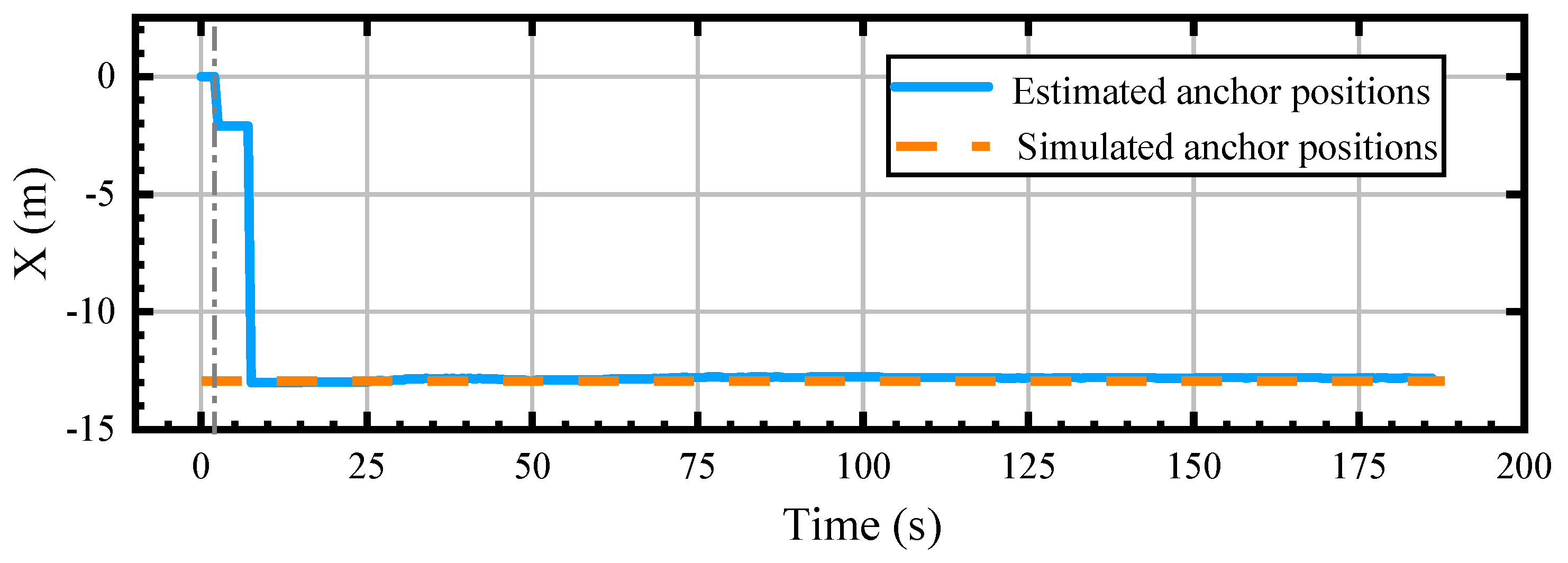
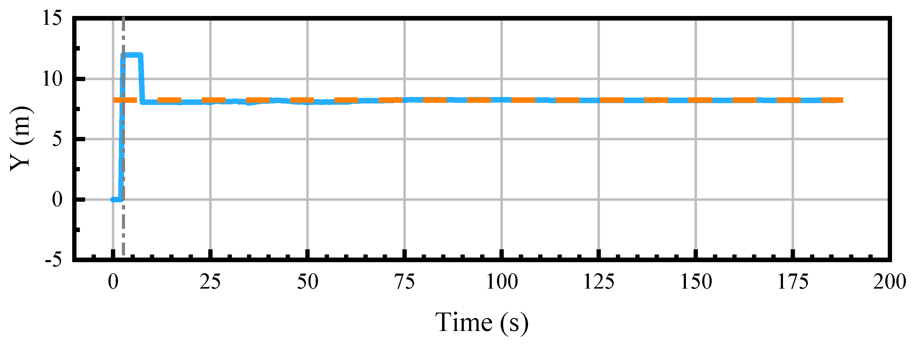
4.1. Simulation Experiment

In order to evaluate the accuracy of the proposed method, we conducted localization tests using the publicly available EUROC dataset [33]. This dataset provides image information and ground-truth poses of image frames. After setting simulated UWB anchor positions, distances between each image frame and the anchors were calculated based on the ground-truth poses of the image frames. To simulate UWB measurement distances, Gaussian white noise with a mean of 0 and a standard deviation of 0.1 m was added to the calculated distances.
In this simulation experiment, data collected from five different UAV flight trajectories with onboard sensors in the EUROC dataset were utilized. The experiment involved using image sequences captured by the 0th camera mounted on the UAV for each trajectory, with each sequence undergoing five complete sets of experiments. In each set, the simulated UWB anchor positions were individually set to P a = { 0 m , 0 m , 0 m } , P a = { 10 m , 10 m , 10 m } , and P a = { 3 m , 4 m , 5 m } to assess the impact of anchor positions on system localization accuracy and anchor position estimation. At system initialization, the initial position of the UWB anchor was set to P a 0 = { 0 m , 0 m , 0 m } , with a scale factor of 1.0 relating the system scale to the metric scale. These experimental designs aim to evaluate the influence of different anchor positions on system performance, facilitating a better understanding of system localization accuracy and anchor position estimation.
The algorithm’s estimated UAV flight trajectories were evaluated using EVO v1.31.0 software [34] by computing the root mean square error (RMSE) of absolute translation error (ATE). The experimental results were compared with state-of-the-art visual–inertial SLAM solutions and visual–ranging-coupled SLAM solutions, as shown in Table 2. EVO v1.31.0 software calculated the similarity transformation between the algorithm’s estimated trajectory and the trajectory collected from the dataset, obtaining the scale factor between the two trajectories. Common SLAM algorithms computed the absolute error between the scale factor and the ground-truth trajectory, as depicted in Table 3.
As shown in Table 2, the proposed algorithm’s estimated trajectories of the MH-01, MH-04, and MH-05 image sequences have the smallest mean square deviation, indicating superior positioning accuracy compared to current mainstream SLAM algorithms and UWB assistant SLAM methods. In the MH-01 image sequence, the visual features are distinct, and there is minimal variation in brightness between images. The algorithm proposed in this paper uses feature point tracking for visual odometry, enabling precise pose estimation. The UAV flight trajectory captured in the MH-01 image sequence is simple, as depicted in Figure 2, and the UWB distance information provides accurate distance constraints. Therefore, the positioning accuracy of the proposed algorithm surpasses that of pure visual algorithms.
In contrast, the MH-04 and MH-05 image sequences exhibit significant lighting variations, with fewer mappable points in certain areas, making pure visual algorithms prone to localization failures. Visual–inertial SLAM algorithms utilize inter-frame preintegration to compute continuous relative pose transformations, and methods combining visual and inertial navigation can function properly but with lower positioning accuracy, such as VINS-MONO [27] and ORB-SLAM3 [4]. UWB measurements are independent and do not accumulate errors, making UWB distance measurements tightly coupled with visual measurements in SLAM algorithms capable of achieving higher precision.
As shown in Table 3, the algorithm proposed in this paper exhibits the smallest scale estimation error across all image sequences in the dataset. The VIO algorithm integrates the acceleration measurements from the IMU to obtain metric-scale positioning information. The zero offset of the IMU device and the drift characteristics of the inertial navigation integration algorithm result in significant scale errors in the positioning information obtained by the VIO algorithm. UWB measurements provide absolute distance information, enabling SLAM methods that combine visual information with distance measurements to generate accurate scaled image trajectories.As shown in Figure 3, the estimated trajectories in the MH-01 dataset are visualized.
As described in Section 3.1, joint tracking of visual and distance measurements can only occur post both visual initialization and UWB anchor position estimation. Section 3.3.3 outlines that by optimizing equations based on candidate frame poses and their distances from UWB anchor points, the UWB anchor positions can be obtained. In the distance and visual joint optimization method detailed in Section 3.5.2, upon selecting new keyframes, global optimization of the map location further refines the information frame poses and UWB anchor positions. In the simulated experiment of the MH-01 image sequence, the variation of UWB anchor positions is depicted by the blue lines in Figure 4, Figure 5 and Figure 6. The initial UWB anchor position is {0, 0, 0}, and approximately 3 s later, the system completes the UWB anchor estimation, placing the estimated anchor point at {3.9, 15.4, 1} in the localization coordinate system. With the addition of keyframes in the system, the UWB anchor position continuously updates, eventually converging to the true UWB anchor position set in the simulation {−12.8, 8.19, 5.22}, as indicated by the orange dashed line in the figure.
The simulated experiments on the EUROC dataset demonstrate that the proposed algorithm, which integrates visual data with UWB ranging, not only addresses the scale ambiguity issue in monocular visual SLAM but also reduces the error in visual SLAM localization accuracy as the distance traveled increases by coupling visual loop closure with distance information. Compared to mainstream visual–inertial odometry (VIO) methods and visual–inertial–distance fusion SLAM methods, the algorithm proposed in this paper exhibits higher system scale accuracy estimation. In certain image sequences, the proposed algorithm achieves higher image position accuracy compared to other common SLAM systems.

4.2. Flight Tests

The outdoor flight experiments validated the effectiveness of the proposed algorithm. A quadcopter equipped with a NVIDIA Jetson Xavier NX processor running at 1600 MHz was used to execute the algorithm in real time. The algorithm estimated the quadcopter’s pose in real time, serving as input to the flight control unit for manual navigation along a predefined flight path.
The experimental UAV, as shown in Figure 7, featured the deployment of the algorithm on a NVIDIA Jetson Xavier NX onboard processor (which is from NVIDIA, Santa Clara, CA, USA). The UAV was equipped with a RealSense D455 camera (which is from Intel, Santa Clara, CA, USA) for capturing environmental images, and the algorithm utilized grayscale images from the left camera at a resolution of 640 × 480 and a capture rate of 30 Hz to reduce computational demands. Real-time distance measurements between the UAV and UWB anchor points were conducted using the LinkTrack P-B UWB (which is from Nooploop, Shenzhen, China) sensor at a frequency of 100 Hz. The CUVA P9 RTK (which is from CUVA, Guangzhou, China) positioning device was employed to continuously record the UAV’s position information as the ground truth for the UAV flight trajectory.
The flight experiments took place in a 10 m × 13 m outdoor environment, with UWB anchor points positioned at the center of the area and calibrated using RTK for accurate positioning. Throughout the experiments, the algorithm captured pose information for each frame and the RTK positioning information for the quadcopter at each moment. Figure 8 illustrates the comparison between the algorithm’s estimated trajectory and the RTK-measured trajectory, aiding in the evaluation of the algorithm’s performance during actual flight.
The proposed algorithm and ORB-SLAM2 (2017) [25] were employed to estimate the trajectory of a flying drone in the experiment. The positioning accuracy of both algorithms was evaluated using EVO. The proposed algorithm achieved an RMSE of ATE 0.23 m, while ORB-SLAM2 (2017) [25] yielded an RMSE of ATE 0.74 m. The scale proportion error between the proposed algorithm’s trajectory and the ground truth was 1.8%.
In Figure 8, the blue solid line represents the trajectory estimated by the proposed algorithm, the orange dashed line indicates the RTK measured trajectory, and the purple line shows the trajectory estimated by ORB-SLAM2 (2017) [25]. The estimated drone trajectory by the proposed algorithm closely matched the ground-truth trajectory, except for a deviation in the circular arc segment towards the end, attributed to drift in the visual estimation with distance and weaker distance constraints in that segment. ORB-SLAM2 (2017) [25], relying solely on visual features, exhibited limited overlap of observed map points at drone turning points, leading to significant positioning errors at the second turn, with errors accumulating over the drone’s flight path.
During the flight, the system continuously optimized the positions of UWB anchor points. The estimated changes in UWB anchor point positions during flight are illustrated in Figure 9, Figure 10 and Figure 11. The blue lines represent the UWB anchor point coordinates estimated by the proposed algorithm, while the orange dashed lines depict the ground-truth coordinates of the UWB anchor points in the system’s localization coordinate system. At the beginning, the initial anchor position is set to {0, 0, 0}. The UWB anchor points were estimated by the system approximately 3 s after the flight. Significant changes in the optimization of UWB anchor points occurred around the 10th second, approaching the ground truth. Throughout the subsequent flight, the UWB anchor point positions were continuously optimized, oscillating near their ground-truth values. As new keyframes were added to the map, changes in visual reprojection errors and distance errors in the global optimization equation led to variations in the estimated positions of the UWB anchor points.
The real flight experiment demonstrates that the proposed algorithm can meet the real-time positioning requirements for drone flights. By combining visual and UWB ranging in SLAM, the algorithm addresses the scale ambiguity and positioning drift issues typically encountered in monocular visual SLAM. Compared to state-of-the-art pure visual SLAM methods, the proposed algorithm in this study achieves a higher positioning accuracy.
The experimental results demonstrate that the proposed method exhibits strong performance in terms of positioning accuracy, both in simulated and real flight tests. When compared to existing state-of-the-art visual SLAM systems, such as ORB-SLAM3 (2021) [4] and VINS-MONO (2018) [27], the IVU-AutoNav method consistently achieves a lower ATE and scale error. Specifically, in tests using the EUROC dataset, the average ATE of IVU-AutoNav ranges from 0.12 to 0.18 m, whereas the ATE of other methods typically exceeds 0.2 m. In real flight tests, the ATE of IVU-AutoNav was measured at 0.23 m, significantly outperforming ORB-SLAM2 (2017) [25], which recorded an ATE of 0.74 m. These results highlight the superior positioning accuracy of the proposed method.
These results not only surpass the performance of existing state-of-the-art visual SLAM systems but also highlight the significant theoretical contributions of our method. The dynamic estimation of the UWB anchor’s position and the continuous optimization of the factor graph enable our system to maintain high accuracy and robustness, even in complex and dynamic environments. The seamless integration of visual and UWB data within our optimization framework demonstrates the potential of our approach to address the limitations of traditional methods and enhance UAV navigation capabilities. These findings underscore the depth and novelty of our theoretical contributions and validate the effectiveness of our proposed solution.
From the perspective of the dynamic optimization of anchor point position estimation, the proposed method in this paper is capable of dynamically optimizing the positions of the UWB anchor points during operation, as validated through experiments. In both simulated and real flight tests, the estimated positions of the UWB anchor points gradually converge to their true values and remain stable in subsequent optimizations. This dynamic optimization mechanism not only enhances the system’s adaptability but also further improves the positioning accuracy.
In terms of adaptability to complex environments, IVU-AutoNav demonstrates robust performance under varying environmental conditions, such as changes in lighting and complex trajectories. For instance, in the MH-04 and MH-05 sequences of the EUROC dataset, despite significant lighting variations and a limited number of mappable points, the proposed method consistently maintains high positioning accuracy. These results underscore the method’s strong adaptability to challenging environments.

5. Conclusions

This study introduces a novel UAV positioning framework named IVU-AutoNav, representing a significant theoretical and practical advancement in autonomous navigation. The key contribution of this research lies in the development of a novel method for estimating the UWB anchor’s position by dynamically integrating visual and UWB data within a factor graph optimization framework. Unlike traditional methods that rely on multiple pre-calibrated anchors or additional sensors, our framework leverages the complementary strengths of visual SLAM and UWB ranging to achieve high-precision localization. The dynamic estimation of the UWB anchor’s position and the continuous optimization of the factor graph ensure that our method maintains high accuracy and robustness, even in complex and dynamic environments. These theoretical innovations not only address the limitations of existing approaches but also provide a deeper understanding of the fusion of visual and UWB technologies for UAV navigation. The experimental results validate the effectiveness of our proposed method, demonstrating its potential to enhance UAV navigation capabilities in real-world applications.
By eliminating the need for multiple pre-calibrated anchors and leveraging the strengths of both visual and UWB data, our method provides a lightweight, computationally efficient, and highly accurate solution for UAV navigation. This work demonstrates the potential of IVU-AutoNav to enhance the operational capabilities of UAVs in scenarios where traditional methods fall short. Through a well-designed factor graph optimization, this method accurately determines the anchor’s position, effectively restoring the scale of the monocular visual SLAM system and improving the overall localization accuracy. In addition, a novel pose optimization graph model is introduced, linking distance errors between the camera and anchor points with the reprojection errors of map points. By leveraging images from the camera and UWB distance measurements, this model enables precise and robust pose optimization, ensuring high-accuracy positioning with a well-defined scale for the monocular visual SLAM system. Compared to existing methods, the proposed method can continuously optimize the UWB anchor position, which can further improve the localization accuracy. The proposed approach is validated through a combination of simulation and flight experiments, demonstrating its performance. Experimental results show a scale error of less than 1.8% compared to the ground truth and an ATE error of 0.23 m. These results surpass the performance of existing state-of-the-art visual SLAM systems, underscoring the potential and effectiveness of the proposed monocular visual–UWB coupled SLAM method in enhancing UAV navigation and localization capabilities.
Although IVU-AutoNav has achieved significant results, there are still some potential limitations that offer directions for future research. Firstly, this paper mentions filtering erroneous measurements in the UWB signal paths through motion models. However, in practical applications, UWB signals may be subject to interference from multipath effects or occlusions. Such interference can introduce errors in distance measurements, which in turn can impact the positioning accuracy. Future research could further investigate methods to enhance the UWB signal’s robustness against such disturbances, or develop more resilient signal processing algorithms to mitigate these errors. Secondly, while IVU-AutoNav is capable of real-time operation on the NVIDIA Jetson Xavier NX platform, its computational complexity remains relatively high. In more complex environments, such as large-scale map construction or multi-robot collaboration, the system’s real-time performance may face challenges. Future studies could focus on optimizing the computational efficiency of the algorithm, for instance, by reducing the number of optimization variables or employing more efficient optimization techniques. Lastly, current research primarily addresses static or semi-dynamic environments; however, in fully dynamic scenarios (such as those involving moving obstacles or rapidly changing scenes), the performance of visual SLAM and UWB fusion could be adversely affected. Future work could explore the integration of deep learning or other perception technologies to enhance the system’s adaptability in dynamic environments.

Author Contributions

Conceptualization, S.B. and J.Z.; methodology, S.B.; software, J.Z.; validation, K.L., X.L. and B.H.; formal analysis, K.L.; investigation, X.L.; resources, S.B.; data curation, J.Z.; writing—original draft preparation, S.B.; writing—review and editing, J.Z.; visualization, K.L.; supervision, X.L.; project administration, B.H.; funding acquisition, S.B. All authors have read and agreed to the published version of the manuscript.

Funding

The work was supported in part by the National Natural Science Foundation of China (NSFC) under Grant 42130112 and the Shaanxi Key Laboratory of Integrated and Intelligent Navigation (SN: SXKLIIN202402002).

Data Availability Statement

The data presented in this study are available on request from the corresponding author due to further processing being required.

Acknowledgments

The authors appreciate the editors and anonymous reviewers for their valuable recommendations.

Conflicts of Interest

The authors declare no conflicts of interest.

References

  1. Gupta, A.; Fernando, X. Simultaneous localization and mapping (slam) and data fusion in unmanned aerial vehicles: Recent advances and challenges. Drones 2022, 6, 85. [Google Scholar] [CrossRef]
  2. Chen, C.; Tian, Y.; Lin, L.; Chen, S.; Li, H.; Wang, Y.; Su, K. Obtaining world coordinate information of UAV in GNSS denied environments. Sensors 2020, 20, 2241. [Google Scholar] [CrossRef] [PubMed]
  3. Liu, X.; Wen, W.; Hsu, L.T. GLIO: Tightly-coupled GNSS/LiDAR/IMU integration for continuous and drift-free state estimation of intelligent vehicles in urban areas. IEEE Trans. Intell. Veh. 2023, 9, 1412–1422. [Google Scholar] [CrossRef]
  4. Campos, C.; Elvira, R.; Rodríguez, J.J.G.; Montiel, J.M.; Tardós, J.D. Orb-slam3: An accurate open-source library for visual, visual–inertial, and multimap slam. IEEE Trans. Robot. 2021, 37, 1874–1890. [Google Scholar] [CrossRef]
  5. Mo, J.; Islam, M.J.; Sattar, J. Fast direct stereo visual SLAM. IEEE Robot. Autom. Lett. 2021, 7, 778–785. [Google Scholar] [CrossRef]
  6. Cai, Y.; Ou, Y.; Qin, T. Improving SLAM techniques with integrated multi-sensor fusion for 3D reconstruction. Sensors 2024, 24, 2033. [Google Scholar] [CrossRef]
  7. Steenbeek, A.; Nex, F. CNN-based dense monocular visual SLAM for real-time UAV exploration in emergency conditions. Drones 2022, 6, 79. [Google Scholar] [CrossRef]
  8. Tian, R.; Zhang, Y.; Zhu, D.; Liang, S.; Coleman, S.; Kerr, D. Accurate and robust scale recovery for monocular visual odometry based on plane geometry. In Proceedings of the 2021 IEEE International Conference on Robotics and Automation (ICRA), Xi’an, China, 30 May–5 June 2021; pp. 5296–5302. [Google Scholar]
  9. Lee, J.; Park, S.Y. PLF-VINS: Real-time monocular visual-inertial SLAM with point-line fusion and parallel-line fusion. IEEE Robot. Autom. Lett. 2021, 6, 7033–7040. [Google Scholar] [CrossRef]
  10. Xia, L.; Meng, D.; Zhang, J.; Zhang, D.; Hu, Z. Visual-inertial simultaneous localization and mapping: Dynamically fused point-line feature extraction and engineered robotic applications. IEEE Trans. Instrum. Meas. 2022, 71, 5019211. [Google Scholar] [CrossRef]
  11. Xu, X.; Zhang, L.; Yang, J.; Cao, C.; Wang, W.; Ran, Y.; Tan, Z.; Luo, M. A review of multi-sensor fusion slam systems based on 3D LIDAR. Remote Sens. 2022, 14, 2835. [Google Scholar] [CrossRef]
  12. Zheng, C.; Xu, W.; Zou, Z.; Hua, T.; Yuan, C.; He, D.; Zhou, B.; Liu, Z.; Lin, J.; Zhu, F.; et al. Fast-livo2: Fast, direct lidar-inertial-visual odometry. IEEE Trans. Robot. 2024, 41, 326–346. [Google Scholar] [CrossRef]
  13. Wang, W.; Wang, C.; Liu, J.; Su, X.; Luo, B.; Zhang, C. HVL-SLAM: Hybrid Vision and LiDAR Fusion for SLAM. IEEE Trans. Geosci. Remote Sens. 2024, 62, 5706514. [Google Scholar] [CrossRef]
  14. Guizilini, V.; Ambruș, R.; Chen, D.; Zakharov, S.; Gaidon, A. Multi-frame self-supervised depth with transformers. In Proceedings of the IEEE/CVF Conference on Computer Vision and Pattern Recognition, New Orleans, LA, USA, 18–24 June 2022; pp. 160–170. [Google Scholar]
  15. Mishima, N.; Seki, A.; Hiura, S. Absolute Scale from Varifocal Monocular Camera through SfM and Defocus Combined. In Proceedings of the BMVC, Online, 22–25 November 2021; p. 28. [Google Scholar]
  16. Zhang, X.; Wang, L.; Su, Y. Visual place recognition: A survey from deep learning perspective. Pattern Recognit. 2021, 113, 107760. [Google Scholar] [CrossRef]
  17. Lin, H.Y.; Yeh, M.C. Drift-free visual slam for mobile robot localization by integrating uwb technology. IEEE Access 2022, 10, 93636–93645. [Google Scholar] [CrossRef]
  18. Gong, Z.; Ying, R.; Wen, F.; Qian, J.; Liu, P. Tightly coupled integration of GNSS and vision SLAM using 10-DoF optimization on manifold. IEEE Sens. J. 2019, 19, 12105–12117. [Google Scholar] [CrossRef]
  19. Qiao, Z.; Xu, A.; Sui, X.; Hao, Y. An integrated indoor positioning method using ORB-SLAM/UWB. J. Navig. Position 2018, 6, 29–34. [Google Scholar]
  20. Obeidat, H.; Shuaieb, W.; Obeidat, O.; Abd-Alhameed, R. A review of indoor localization techniques and wireless technologies. Wirel. Pers. Commun. 2021, 119, 289–327. [Google Scholar] [CrossRef]
  21. Elsanhoury, M.; Mäkelä, P.; Koljonen, J.; Välisuo, P.; Shamsuzzoha, A.; Mantere, T.; Elmusrati, M.; Kuusniemi, H. Precision positioning for smart logistics using ultra-wideband technology-based indoor navigation: A review. IEEE Access 2022, 10, 44413–44445. [Google Scholar] [CrossRef]
  22. Kim Geok, T.; Zar Aung, K.; Sandar Aung, M.; Thu Soe, M.; Abdaziz, A.; Pao Liew, C.; Hossain, F.; Tso, C.P.; Yong, W.H. Review of indoor positioning: Radio wave technology. Appl. Sci. 2020, 11, 279. [Google Scholar] [CrossRef]
  23. Nguyen, T.H.; Nguyen, T.M.; Xie, L. Tightly-coupled single-anchor ultra-wideband-aided monocular visual odometry system. In Proceedings of the 2020 IEEE International Conference on Robotics and Automation (ICRA), Paris, France, 31 May–31 August 2020; pp. 665–671. [Google Scholar]
  24. Cao, Y.; Beltrame, G. VIR-SLAM: Visual, inertial, and ranging SLAM for single and multi-robot systems. Auton. Robot. 2021, 45, 905–917. [Google Scholar] [CrossRef]
  25. Mur-Artal, R.; Tardós, J.D. Orb-slam2: An open-source slam system for monocular, stereo, and rgb-d cameras. IEEE Trans. Robot. 2017, 33, 1255–1262. [Google Scholar] [CrossRef]
  26. Cadena, C.; Carlone, L.; Carrillo, H.; Latif, Y.; Scaramuzza, D.; Neira, J.; Reid, I.; Leonard, J.J. Past, present, and future of simultaneous localization and mapping: Toward the robust-perception age. IEEE Trans. Robot. 2016, 32, 1309–1332. [Google Scholar] [CrossRef]
  27. Qin, T.; Li, P.; Shen, S. Vins-mono: A robust and versatile monocular visual-inertial state estimator. IEEE Trans. Robot. 2018, 34, 1004–1020. [Google Scholar] [CrossRef]
  28. Saputra, M.R.U.; Markham, A.; Trigoni, N. Visual SLAM and structure from motion in dynamic environments: A survey. ACM Comput. Surv. CSUR 2018, 51, 1–36. [Google Scholar] [CrossRef]
  29. Tateno, K.; Tombari, F.; Laina, I.; Navab, N. Cnn-slam: Real-time dense monocular slam with learned depth prediction. In Proceedings of the IEEE Conference on Computer Vision and Pattern Recognition, Honolulu, HI, USA, 21–26 July 2017; pp. 6243–6252. [Google Scholar]
  30. Subedi, S.; Pyun, J.Y. A survey of smartphone-based indoor positioning system using RF-based wireless technologies. Sensors 2020, 20, 7230. [Google Scholar] [CrossRef] [PubMed]
  31. Nguyen, T.H.; Nguyen, T.M.; Xie, L. Range-Focused Fusion of Camera-IMU-UWB for Accurate and Drift-Reduced Localization. IEEE Robot. Autom. Lett. 2021, 6, 1678–1685. [Google Scholar] [CrossRef]
  32. Li, J.; Wang, S.; Hao, J.; Ma, B.; Chu, H.K. UVIO: Adaptive Kalman Filtering UWB-Aided Visual-Inertial SLAM System for Complex Indoor Environments. Remote Sens. 2024, 16, 3245. [Google Scholar] [CrossRef]
  33. Burri, M.; Nikolic, J.; Gohl, P.; Schneider, T.; Rehder, J.; Omari, S.; Achtelik, M.W.; Siegwart, R. The EuRoC micro aerial vehicle datasets. Int. J. Robot. Res. 2016, 35, 1157–1163. [Google Scholar] [CrossRef]
  34. Sturm, J.; Engelhard, N.; Endres, F.; Burgard, W.; Cremers, D. A benchmark for the evaluation of RGB-D SLAM systems. In Proceedings of the 2012 IEEE/RSJ International Conference on Intelligent Robots and Systems, Algarve, Portugal, 7–12 October 2012; pp. 573–580. [Google Scholar]
  35. Leutenegger, S.; Lynen, S.; Bosse, M.; Siegwart, R.; Furgale, P. Keyframe-based visual–inertial odometry using nonlinear optimization. Int. J. Robot. Res. 2015, 34, 314–334. [Google Scholar] [CrossRef]
Figure 1. Overview of proposed method. The UWB and visual SLAM system can be divided into four main phases: visual initialization, UWB candidate frame collection, system initialization, and tightly coupled UWB and visual SLAM. In the image, the black dashed line represents the measured distance, the red dashed line shows the true trajectory of the drone, the blue line represents the trajectory estimated purely by vision, and the green line represents the trajectory obtained by combining vision and UWB.
Drones 09 00162 g001
Figure 2. The architecture of proposed integrated visual and UWB framework.
Drones 09 00162 g002
Figure 3. The trajectories estimated by the proposed algorithm in MH−01 dataset.
Drones 09 00162 g003
Figure 4. Estimated and ground−truth position of anchor in X−coordinate on MH−01 dataset.
Drones 09 00162 g004
Figure 5. Estimated and ground−truth position of anchor in Y−coordinate on MH−01 dataset.
Drones 09 00162 g005
Figure 6. Estimated and ground−truth position of anchor in Z−coordinate on MH−01 dataset.
Drones 09 00162 g006
Figure 7. Figure illustrating the outdoor experimental setup, featuring a UAV on the left and the experimental site on the right.
Drones 09 00162 g007
Figure 8. Outdoor experimental flight trajectory.
Drones 09 00162 g008
Figure 9. Estimated anchor point X−coordinate in outdoor experiments.
Drones 09 00162 g009
Figure 10. Estimated anchor point Y−coordinate in outdoor experiments.
Drones 09 00162 g010
Figure 11. Estimated anchor point Z−coordinate in outdoor experiments.
Drones 09 00162 g011
Table 1. Summary of symbols and their descriptions. The bold represents vectors, and the non-bold represents scalars.
SymbolDescription
x * Optimization parameter, defined as { ϕ , t }
ϕ Lie algebra corresponding to the pose of the frame
t Position of the frame
u i , v i Pixel positions of the feature points
f x , f y Focal lengths of the camera
c x , c y Principal point offsets of the camera
p i x , p i y , p i z Position of the map point in 3D space
t x , t y , t z Components of the translation vector t
R i j Rotation matrix of the frame
ϕ 1 , ϕ 2 , ϕ 3 Components of the Lie algebra ϕ
π Camera projection matrix
p Position of the map point { p x , p y , p z }
u , v Pixel locations of the projected map point
R Pose matrix of the image frame
F Projection equation corresponding to the image frame
u 1 , v 1 , u 2 , v 2 Pixel positions of the feature point pairs
d a , b k 2 , d a , b k 1 , d a , b k Distances measured by UWB for frames k 2 , k 1 , and k
δ d k 1 , δ d k Change in distance between consecutive frames
fThreshold for the increase ratio of distance change
cSpeed of light
τ S a Timestamp when anchor a transmits the request signal
τ R a Timestamp when anchor a receives the response signal
δ τ Signal processing delay
η τ Measurement noise in distance estimation
Ω Covariance matrix of the Gaussian noise
d a , b n , d a , b n + 1 UWB ranging values at the n-th and ( n + 1 ) -th measurements
τ n , τ n + 1 Timestamps of the n-th and ( n + 1 ) -th UWB measurements
τ k Timestamp of the k-th image acquisition
· Euclidean norm of a parameter vector
P u k w Position of the UWB receiver on the UAV in the navigation coordinate system at time k
P a k w Position of the UWB anchor point in the navigation coordinate system at time k
P u b Installation pose of the UWB receiver on the UAV
T w , b k Transformation from the UAV body coordinate system to the navigation coordinate system at time k
P a Position of the UWB anchor in the SLAM system
sScale factor between the system scale and the metric scale
NNumber of keyframes used for system initialization
e i d Error in UWB distance measurements
d i m , d i e Measured and computed distances in the UWB system
e i , j r Reprojection error of the j-th feature point in the i-th information frame
W i , j r Information matrix for the reprojection error
W i d Information matrix for the UWB error
l i Reciprocal of the number of scale levels at which the feature point is captured in the pyramid system
Table 2. Various methods’ positioning RMSE values of ATE comparisons (unit: m). The bold emphasizes the minimum error value among all methods.
MethodMH-01MH-02MH-03MH-04MH-05
IVU-AutoNav (Our Method)0.120.150.130.140.18
VINS_MONO (2018) [27]0.270.150.140.250.35
OKVIS (2015) [35]0.160.220.240.340.47
ORB_SLAM3 (2021) [4]0.130.100.120.200.22
Method in (2020) [23]0.160.110.150.250.24
VIR SLAM (2021) [24]0.180.190.260.370.29
Table 3. Scale error comparisons (unit: percentage). The bold emphasizes the result of our method.
MethodMH-01MH-02MH-03MH-04MH-05
IVU-AutoNav (Our Method)99.6%97.5%96.8%101.2%99.8%
VINS MONO (2018) [27]91.7%85.2%127.2%96.4%110.4%
OKVIS (2015) [35]121.4%112%92.8%91.5%121.5%
ORB_SLAM3 (2021) [4]98.2%95.1%111.4%102.7%105.1%
Disclaimer/Publisher’s Note: The statements, opinions and data contained in all publications are solely those of the individual author(s) and contributor(s) and not of MDPI and/or the editor(s). MDPI and/or the editor(s) disclaim responsibility for any injury to people or property resulting from any ideas, methods, instructions or products referred to in the content.

