Article

Online Multi-AUV Trajectory Planning for Underwater Sweep Video Sensing in Unknown and Uneven Seafloor Environments

by
Talal S. Almuzaini
1,2,* and
Andrey V. Savkin
1
1
School of Electrical Engineering and Telecommunications, University of New South Wales, Sydney 2052, Australia
2
School of Electrical Engineering, Islamic University of Madinah, Madinah 42351, Saudi Arabia
*
Author to whom correspondence should be addressed.
Drones 2025, 9(11), 735; https://doi.org/10.3390/drones9110735
Submission received: 21 September 2025 / Revised: 21 October 2025 / Accepted: 22 October 2025 / Published: 23 October 2025

Highlights

What are the main findings?
  • The proposed online multi-AUV method achieves reliable sweep video coverage of unknown and uneven seafloors while maintaining safety margins and adapting to terrain occlusions.
  • Benchmarking against lawnmower strategies shows that the proposed approach provides higher coverage, safer trajectories, and more efficient mapping under challenging terrain conditions.
What are the implications of the main findings?
  • The proposed method offers an effective solution for occlusion-aware underwater sensing missions over unknown and uneven seafloor environments where fixed-pattern approaches are inadequate.
  • The framework can be extended to larger multi-AUV systems and real-world deployments, enabling more efficient video sensing applications.

Abstract

Autonomous underwater vehicles (AUVs) play a critical role in underwater remote sensing and monitoring applications. This paper addresses the problem of navigating multiple AUVs to perform sweep video sensing of unknown underwater regions over uneven seafloors, where visibility is limited by the conical field of view (FoV) of the onboard cameras and by occlusions caused by terrain. Coverage is formulated as a feasibility objective of achieving a prescribed target fraction while respecting vehicle kinematics, actuation limits, terrain clearance, and inter-vehicle spacing constraints. We propose an online, occlusion-aware trajectory planning algorithm that integrates frontier-based goal selection, safe viewing depth estimation with clearance constraints, and model predictive control (MPC) for trajectory tracking. The algorithm adaptively guides a team of AUVs to preserve line of sight (LoS) visibility, maintain safe separation, and ensure sufficient clearance while progressively expanding coverage. The approach is validated through MATLAB simulations on randomly generated 2.5D seafloor surfaces with varying elevation characteristics. Benchmarking against classical lawnmower baselines demonstrates the effectiveness of the proposed method in achieving occlusion-aware coverage in scenarios where fixed-pattern strategies are insufficient.

1. Introduction

Driven by the global pursuit of natural resources and the increasing focus on space exploration, underwater research has gained significant attention in recent years [1,2]. Autonomous Underwater Vehicles (AUVs) have emerged as indispensable tools in this domain, supporting a wide range of missions, including search and rescue, seabed mapping, infrastructure inspection, and environmental monitoring and cleanup [3,4]. Their ability to operate autonomously in complex and dynamic marine environments has expanded the scope of underwater exploration and data acquisition [5,6].
Within this context, underwater sweep video sensing plays a central role in observing and understanding submerged environments [7]. It enables continuous and detailed data collection, facilitating the assessment of underwater features and environmental conditions [1]. These capabilities facilitate early detection of critical events, such as pollution, the presence of hazardous substances, sediment contamination, or habitat degradation, thus contributing to the protection and sustainable management of marine ecosystems [4,8,9,10]. Underwater video sensing and surveillance has therefore become a cornerstone of modern marine research and conservation efforts.
Among available technologies, AUVs offer distinct advantages for sweep video sensing. Their operational flexibility and autonomy make them particularly suited for deployment in remote, hazardous, or ecologically sensitive areas [5,11]. Compared to traditional methods, they reduce both operational cost and mission duration while maintaining high-quality data acquisition [9,12]. Moreover, AUVs can autonomously collect and transmit data in real time, addressing key challenges related to trajectory planning, control, and communication in submerged environments [5].
Effective underwater sweep video sensing requires integrating mission-specific sensors, such as ground-facing cameras [5]. The camera’s field of view (FoV) is a critical factor influencing the vehicle’s trajectory, especially in missions that demand continuous monitoring of a region of interest [13]. Successful video sensing depends on maintaining this region within the camera’s FoV throughout the mission [13,14]. However, uneven seafloor topography, characterized by knolls, ridges, and depressions, can obstruct line-of-sight (LoS), creating blind spots and leaving parts of the region uncovered [15]. To overcome these challenges, advanced path planning algorithms are required to generate feasible trajectories that preserve continuous LoS, ensure complete coverage, and avoid occlusions caused by terrain variability [7].
Ensuring complete coverage over an uneven seafloor is inherently difficult, and the challenge intensifies when the environment is unknown and no prior topographic information is available. In known environments, coverage can be planned offline with optimized trajectories designed to mitigate occlusions caused by terrain irregularities [7]. In contrast, in unknown environments, such pre-computed paths are not feasible. AUVs must instead perform online trajectory planning, adapting their motion in real time based on sensor data to overcome LoS blockages, prevent coverage gaps, and reduce the risk of collisions [16].
Single-AUV operations in large, unknown underwater environments are further constrained by endurance, coverage, and adaptability limitations, making coordinated multi-AUV deployment a practical solution for efficient and reliable underwater video sensing [17,18]. Deploying multiple AUVs enables faster and wider area coverage, improved energy efficiency through distributed task execution, and enhanced system robustness [6,17,18,19]. Collaborative strategies allow for optimized task allocation that avoids redundant paths and ensures full coverage with minimal overlap [6,19]. Furthermore, the ability to dynamically adjust formations enables the fleet to respond more effectively to visibility constraints imposed by uneven terrain [17,19]. However, realizing these benefits depends critically on precise trajectory planning for each AUV to maintain video sensing quality while navigating over variable, unknown topography. This work addresses this need by developing trajectory planning techniques for high-performance multi-AUV underwater video sensing of unknown and uneven seafloors, while accounting for operational efficiency, coverage quality, and LoS continuity [7].
In summary, we address the problem of multi-AUV sweep video sensing over an unknown and uneven seafloor. Each vehicle is equipped with a ground-facing camera that provides a conical FoV and collects local bathymetric data during motion. The objective is to achieve complete visual coverage while satisfying range, depth, and minimum-clearance constraints and avoiding inter-vehicle conflicts. A key challenge is that coverage can only be credited when a point on the seafloor lies within the FoV and is directly visible under clear LoS.

1.1. Contribution

This paper presents an online multi-AUV trajectory planning algorithm for occlusion-aware sweep video sensing of an underwater region over unknown and uneven seafloors. The objective is to achieve a desired coverage with efficient motion while ensuring both inter-vehicle safety and maintaining clearance from the terrain. Coverage is only advanced when a point on the seafloor is directly observable, meaning it lies within the FoV of the onboard camera and has an unobstructed LoS.
The proposed framework operates in an iterative sense-assign-track cycle. Each cycle begins with an occlusion-aware sensing update that refines both a binary coverage map and a 2.5D elevation map of the seafloor. Frontier cells, located at the boundary between explored and unexplored areas, are extracted as candidate goals. AUVs are then assigned to nearby frontiers using a greedy nearest-neighbor rule with a spacing constraint that promotes safe allocation. For each assigned goal, a safe viewing depth is selected based on the nearest known elevation in the current map, assuming local surface continuity, while enforcing terrain clearance and depth limits. Motion toward the goal is generated through a short-horizon MPC, which minimizes position error and clearance violations under kinematic and separation constraints. Each AUV executes only the first control, keeps its goal latched until reached within tolerance, and then triggers reassignment. The loop continues until the target coverage is achieved.
In summary, the key contributions are as follows:
  • Online occlusion-aware multi-AUV coverage framework: An online method for sweep coverage of unknown and uneven seafloors in video sensing tasks. The environment is modeled as a 2.5D elevation grid where depths are progressively revealed through sensing. An occlusion-aware sensor model ensures that only truly visible cells within the FoV contribute to both the terrain estimate and coverage map, enabling safe and terrain-aware coverage expansion.
  • Goal generation and assignment: Frontier cells, located at the boundary between explored and unexplored regions, are extracted as candidate goals. Each AUV is assigned to a nearby unallocated frontier using a greedy nearest frontier rule with a spacing constraint, distributing the fleet without centralized optimization and requiring only pose, goal, and maps broadcasts. Safe goal altitudes are then computed from nearest known terrain estimates, ensuring that the FoV footprint remains within range and satisfies terrain clearance and depth limits.
  • Adaptive trajectory tracking and termination: Short-horizon MPC generates trajectories that balance goal progress, clearance safety, and actuation limits. Each AUV maintains its current until a reach tolerance is met, after which reassignment occurs. The mission terminates once the global coverage ratio exceeds a predefined threshold.

1.2. Related Work

Underwater video sensing for area coverage relies on the coverage path planning (CPP) formulation. In CPP, the goal is to compute a trajectory that covers the entire target region from an initial to a terminal state while detecting and avoiding obstacles [20]. This problem is widely studied in robotics, with applications spanning autonomous lawn mowing, surveillance, agriculture, and structural inspection [21,22,23,24].
Authors in [25] classify coverage path planning techniques into classical and heuristic approaches, highlighting that many employ canonical sweep strategies such as back-and-forth (lawnmower) motions and boustrophedon decompositions, often posed in two-dimensional or fixed-altitude workspaces. When a map is available in advance, cellular decomposition provides a convenient strategy to divide the region into smaller grid or polygonal cells [26,27]. A representative exact method is the boustrophedon decomposition by the authors in [28], which partitions free space into sweepable cells so the robot can traverse parallel strips with completeness guarantees. However, planar models of coverage generally measure progress by ground-footprint overlap, failing to account for 3D self-occlusions [25].
When terrain blocks the LoS between the vehicle and the target area, footprint-only accounting can overestimate what is observed. LoS-aware planning addresses this by using elevation models or ray casting checks so that seafloor points are counted only if directly visible [7]. For example, ref. [7] proposes an occlusion-aware AUV coverage framework that selects viewpoints ensuring visibility of seafloor points despite terrain occlusions. Following this line of work, our approach assumes the sensor inherently returns only cells within the FoV and unobstructed, ensuring strict occlusion-aware accounting when navigating AUVs over the seafloor.
In unknown environments, offline coverage path planning methods that rely a prior global map cannot guarantee completeness. Online coverage, by contrast, interleaves sensing with replanning, progressively expanding the map and reducing the unexplored region over time [29]. In this direction, ref. [30] presents an efficient method for large-scale 3D environments, while ref. [29] introduces a receding-horizon next-best-view strategy that serves as a standard benchmark. In the underwater context, authors in [31] propose a multisensor online 3D view-planning framework for autonomous exploration, demonstrating the adaptability of online exploration to demanding marine conditions.
Frontier-based exploration has remained central to unknown environment planning since Yamauchi introduced the idea of treating the boundary between known and unknown regions as exploration goals [32]. Numerous refinements have been proposed ever since to accelerate frontier detection and improve scalability. For example, authors in [33] introduce expanding wavefront detection to more efficiently identify frontier cells, with subsequent studies providing further algorithmic improvements for robust and scalable detection [34]. More recently, frontier selection has been combined with deep reinforcement learning to enhance exploration efficiency in large or complex environments [35]. In the marine domain, authors in [36] extend frontier-based viewpoint generation to underwater settings, demonstrating its effectiveness for exploration and mapping tasks. Collectively, these efforts highlight the adaptability of frontier-based strategies and their continued importance for navigating unknown environments. Building on this foundation, we employ frontier-based exploration for multi-AUV coverage by combining frontier selection with altitude planning.
MPC provides a receding-horizon framework that enforces state and input constraints while adapting to updated sensor information [37]. Its application to AUVs has been explored under diverse challenges. For instance, ref. [38] proposes a 3D trajectory-tracking method capable of handling operational constraints in complex ocean conditions, while ref. [39] incorporates Lyapunov stability analysis to improve robustness against disturbances. To address uncertainty, authors in [40] develop a tube-based, event-triggered MPC scheme that enhances resilience to disturbances and parameter variability. More recently, the authors in [41] extend MPC to over-actuated AUVs through a hybrid approach integrating variable-universe s-plane algorithms for precise 3D tracking. The study in [42] further presents a localization aware, MPC-based path planning approach in which a USV coordinates a fleet of AUVs to enhance energy efficiency, coverage, and localization accuracy given acoustic communication constraints. Collectively, these contributions highlight the versatility of MPC as a robust framework for underwater motion planning.
Distinct from prior coverage and exploration approaches, this study presents an online multi-AUV framework that achieves occlusion-aware coverage of unknown and uneven seafloors. The method integrates frontier-based goal generation, safe altitude selection from an evolving terrain map, and short-horizon MPC for coordinated motion under kinematic and safety constraints. Together, these components constitute a novel solution for reliable video coverage in such environments, where traditional sweep patterns tend to overestimate coverage and information-gain policies may fail to account for critical occlusion effects.

1.3. Article Organization

The rest of this article is organized as follows. Section 2 introduces the materials and methods, including the system model, essential definitions, problem formulation, and the proposed solution. Section 3 presents the results and discussion, assessing the performance of the proposed method. Section 4 concludes the paper and outlines future directions.

2. Materials and Methods

This section presents the foundational models, underlying assumptions, and conceptual framework of the proposed approach. It provides a detailed description of the system components and constraints, formally defines the problem, and introduces the proposed solution strategy.

2.1. System Model

We consider a team of M AUVs, indexed by i = 1 , , M . Each vehicle is equipped with a ground-facing camera and tasked with performing sweep video sensing of an underwater region over an unknown and uneven seafloor. The seafloor is represented as a 2.5D elevation map defined by a function T ( x , y ) , where any point on the surface is given by ( x , y , T ( x , y ) ) [22,43]. The elevation values satisfy T x , y   <   0 .
The region of interest is defined as a bounded horizontal 2D area A = x min , x max   ×   [ y min , y max ] , located on the seafloor. Its boundary coordinates are specified during the mission planning from available surface data and are maintained underwater using standard onboard navigation and localization techniques [44]. Apart from this predefined boundary, the interior seafloor topography is unknown prior to deployment, and no bathymetric map or elevation data are available.
We discretize A into a uniform grid G with resolution σ > 0 as [43]
G = x a , y b   x a = x min + a σ ,           y b = y min + b σ ,
where a = 0 ,   , D x and b = 0 , , D y , with integers D x and D y chosen such that x min + D x σ = x max and y min + D y σ = y max [see Figure 1]. For each grid cell ( x a , y b ) G , the elevation T ( x a , y b ) is initially unknown and becomes available only through onboard sensing. At time t , each grid cell is associated with a coverage flag C t ( x a , y b ) { 0,1 } and, if observed, a local elevation estimate T ^ t ( x a , y b ) . The coverage status and the estimated terrain elevation are shared across all AUVs, allowing any single observation to update the corresponding cell.
The motion of each AUV i is governed by the following kinematic model [7,45]:
x ˙ i ( t ) = u i t   cos   ψ i t
y ˙ i t = u i t sin ψ i t
z ˙ i ( t ) = w i t
ψ ˙ i t = r i t ,
where the position of AUV i is denoted by p i t = ( x i t ,   y i t ,   z i t ) , and its orientation is described by the yaw angle ψ i ( t ) [ 0 ,   2 π ) . The control inputs consist of the surge velocity u i ( t ) [ 0 , u max ] , heave velocity w i ( t ) [ w min , w max ] , and yaw rate r i ( t ) [ r max ,   r max ] . When r i ( t )     0 , the AUV follows a circular trajectory with a turn radius given by R i ( t )   = u i ( t ) / r i ( t ) [7].
We use depth z 0 , with z = 0 at the surface. For safe operation, the depth of each AUV is bounded by Z min  and  Z max , where 0 > Z max > Z min . Each AUV i must therefore maintain its depth within the following range [7]:
z i t Z min , Z max .
To ensure safe clearance from the seafloor, the following condition must hold for all t [7]:
h i t h safe ,
where h i t = z i t T ( x i ( t ) , y i ( t ) ) denotes the altitude of AUV i above the seafloor at the time t , and h safe > 0 is a positive safety constant. Similarly, to avoid inter-vehicle collisions, the distance between any two AUVs i and j with i j must satisfy the condition [7,46]:
ε i j t ε safe ,
where ε i j ( t ) denotes the Euclidean distance between AUVs i and j at time t , and ε safe > 0 specifies the minimum required separation distance [7].
At the start of the mission, all AUVs are deployed on the water surface above the region of interest A and then descend to their prescribed starting depths within the safe range [ Z min , Z max ] . Their initial horizontal positions are assigned within a small circle centered at the midpoint of A , and their initial headings ψ i ( 0 ) are uniformly distributed. Each AUV’s initial depth z i ( 0 ) is set to a shallow value, allowing the algorithm to determine subsequent safe viewing depths during the coverage process.
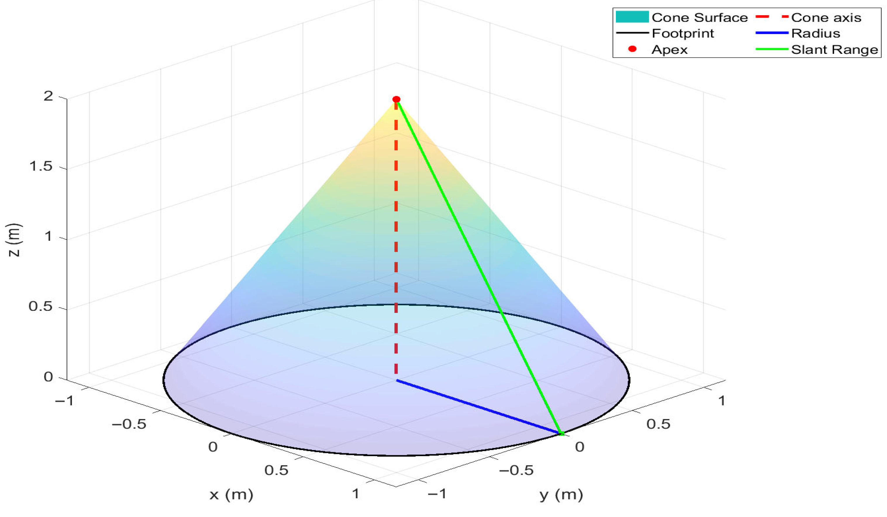
The onboard ground-facing camera of each AUV i , located at ( x i ( t ) ,   y i ( t ) ,   z i ( t ) ) , provides a conical FoV defined by an apex angle θ ( 0 , π ) and a maximum sensing range R [see Figure 2] [7,47]. The radius ρ i ( t ) of the FoV footprint on the seafloor is given by
ρ i ( t ) = h i t   t a n ( θ 2 ) ,
centered at ( x i ( t ) ,   y i ( t ) ,   T ( x i t , y i t ) ) , where T ( x i t , y i t ) < z i ( t ) . To ensure that the footprint remains within the sensor’s effective range, the following condition must hold:
h i t R c o s ( θ 2 ) .
This constraint ensures that the projected footprint does not exceed the slant sensing range R . Furthermore, in this design, the camera is assumed to be stabilized using a gimbal [48].
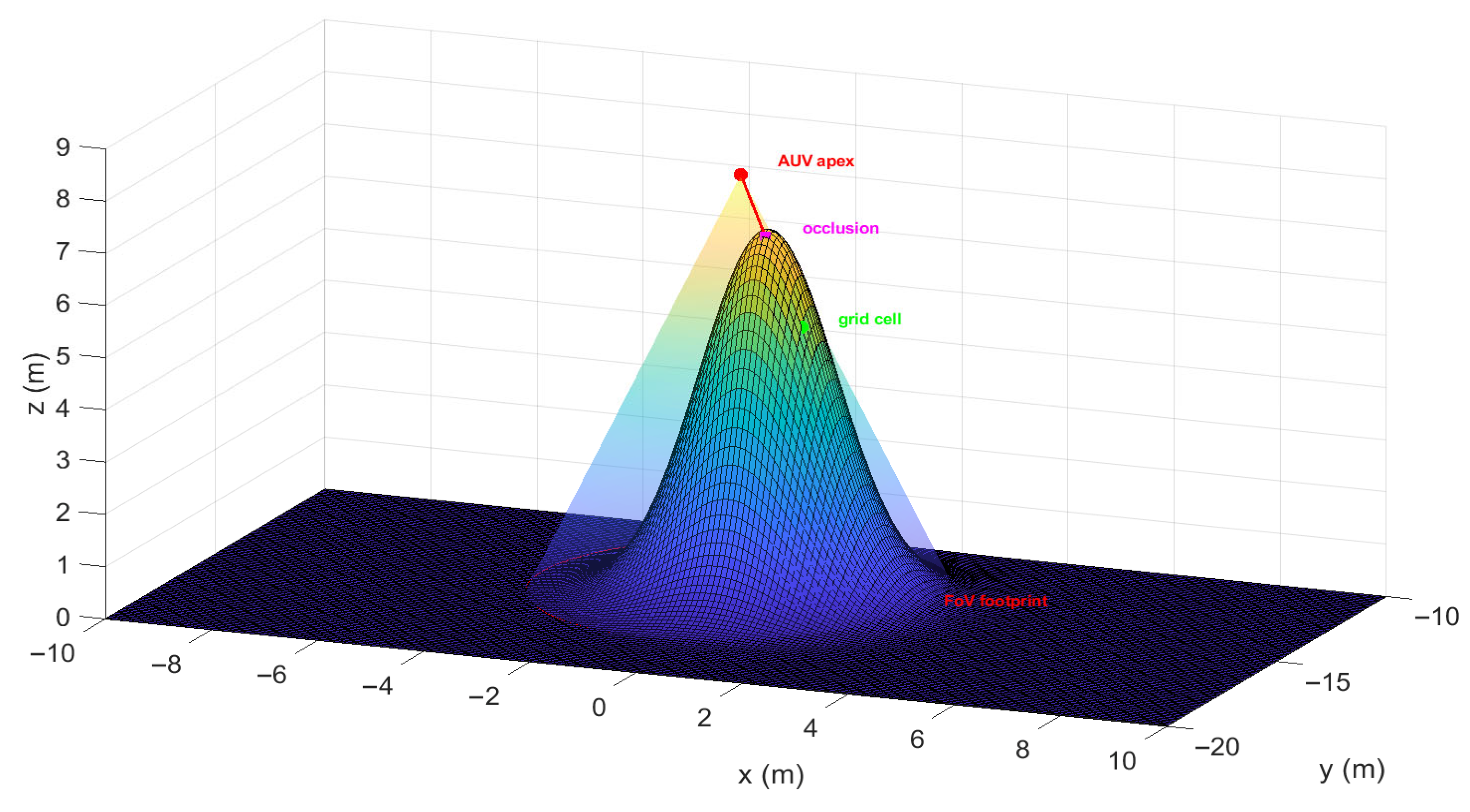
We assume that the camera return model incorporates an occlusion-aware feature. Specifically, a grid cell ( x a , y b ) is considered visible only if it lies within the footprint defined in (6), satisfies the constraint in (7), and maintains a clear LoS to the AUV. In other words, the sensing process inherently enforces LoS consistency for cells within the footprint. Any cell inside the footprint but with an occluded LoS is not considered covered, as illustrated in Figure 3. For each covered cell ( x a , y b ) , the coverage map is updated such that C t x a , y b   = 1 , and the local terrain estimate is set to T ^ t x a , y b   = T ( x a , y b ) .
All AUVs operate under a decentralized communication scheme. During the mission, they periodically exchange essential information, including their current pose ( x i t ,   y i t ,   z i t , ψ i ( t ) ) , assigned goal, and newly sensed coverage and elevation cells. This exchange ensures that the shared coverage map C t and elevation estimate T ^ t remain consistent across the team. These brief broadcasts, performed at each cycle through underwater acoustic links [49], are sufficient for maintaining inter-vehicle separation and cooperative coverage while avoiding the need for a central coordinator.

2.2. Problem Statement

The aim of this paper is to achieve a specified target coverage of the region of interest A over an unknown and uneven seafloor, while ensuring safe terrain clearance and avoiding inter-vehicle collisions among the AUVs. The coverage ratio at time t is defined as
Q ( t ) = 1 G ( x a , y b ) G C t x a , y b ,
where G denotes the total number of grid cells. Given a target coverage fraction λ target ( 0 ,   1 ) , the objective is to navigate a team of AUVs, moving according to the kinematic model in (2) and subject to the constraints (3)–(5), such that the closed loop system achieves the target coverage λ target under the FoV constraints (6) and (7) within the occlusion-aware camera model. Formally, the problem is to achieve a finite time t = τ hit such that
Q ( τ hit ) λ target .
Achieving this condition ensures that a desired fraction of the region is reliably observed despite seafloor irregularities and occlusion effects, thereby enabling effective and safe multi-AUV video sensing of unknown environments.

2.3. Proposed Solution

We propose an occlusion-aware sweep video sensing algorithm to guide multiple AUVs in achieving the target coverage λ target of the underwater region A situated over an unknown and uneven seafloor. The method operates online in sense-assign-track cycles with event-triggered goal reassignment. In each cycle, every AUV performs LoS-occlusion-aware scanning using its onboard camera, updating both the coverage map and the elevation estimate T ^ t within its FoV. From the updated map, frontiers, uncovered cells adjacent to covered ones, are extracted and utilized as candidate goals.
Frontier allocation is performed using a greedy strategy designed to minimize travel distance while avoiding conflicts between assigned goals. For each assigned goal, a safe viewing depth is computed based on the nearest known elevation in T ^ t associated with that frontier. Each AUV then executes a short-horizon MPC to track its assigned goal while satisfying the vehicle kinematics and safety constraints defined in (3)–(5). Goals are reassigned only after arrival, meaning that an AUV keeps its current goal until it reaches the specified tolerance. Once the goal is reached, a new frontier is allocated, and the process continues until the desired coverage is achieved. The complete procedure is summarized in Algorithm 1.
Algorithm 1. Occlusion-Aware Multi-AUV sweep coverage
Inputs: Number of AUVs ( M ); grid ( G ); camera parameters ( θ , R ); safety parameters ( h safe , ε safe , Z min , Z max ); target coverage ( λ target ); control limits ( u max , w max , w min , r max ); prediction horizon ( H ); sampling period ( δ ); footprint scale ( η ); goal-reaching tolerance ( ϵ )
Outputs: coverage map ( C t ) ; elevation estimate ( T ^ t ); coverage history ( Q ( t ) ); hitting time ( τ hit )
1Init: p i t , ψ i t ;   C t = 0 ;     T ^ t = NaN ;   ξ i t = 1 for i = 1 , ,   M ;     t   = 0 ; G t   =
2while Q ( t ) < λ target do
3Sense and update (per AUV i ):
4 for each ( x a , y b ) G do
5  if V i s i b l e i x a , y b ; θ , R = 1 then
6     C t x a , y b   = 1 ; T ^ t x a , y b   = T ( x a , y b )
7  end if
8 end for
9Frontiers:
10   F t = ( x a , y b ) G   C t x a , y b = 0   and     4 -nbr ( x a , y b )   with   C t x a , y b = 1 }
11Assign goals and altitude:
12 for each AUV i where ξ i t = 1 do
13   g i   = arg min f n F ( t ) G ( t ) κ i , n , κ i , n = x i , y i f n   s.t. f n g j ε safe ,     g j G ( t )
14  if g i exist then
15    G t = G t { g i }
16    T t ~ g i = nearestKnown ( g i , T ^ t )
17     ρ des   = η R sin ( θ / 2 ) ; ζ = m a x { h safe , ρ des tan ( θ / 2 ) }
18     z i , goal   = T t ~ ( g i ) + ζ
19     ω i   = ( x i , goal , y i , goal , z i , goal )
20  end if
21 end for
22Track and trigger:
23 for each AUV i with ω i do
24  solve MPC (Horizon H ); apply first input
25  If x i , y i , z i ω i ϵ   t h e n   ξ i t   = 1   else   ξ i t   = 0
26  end if
27 end for
28 t   = t + δ
29end while
30Return: C t ; T ^ t ; Q t ;   τ hit
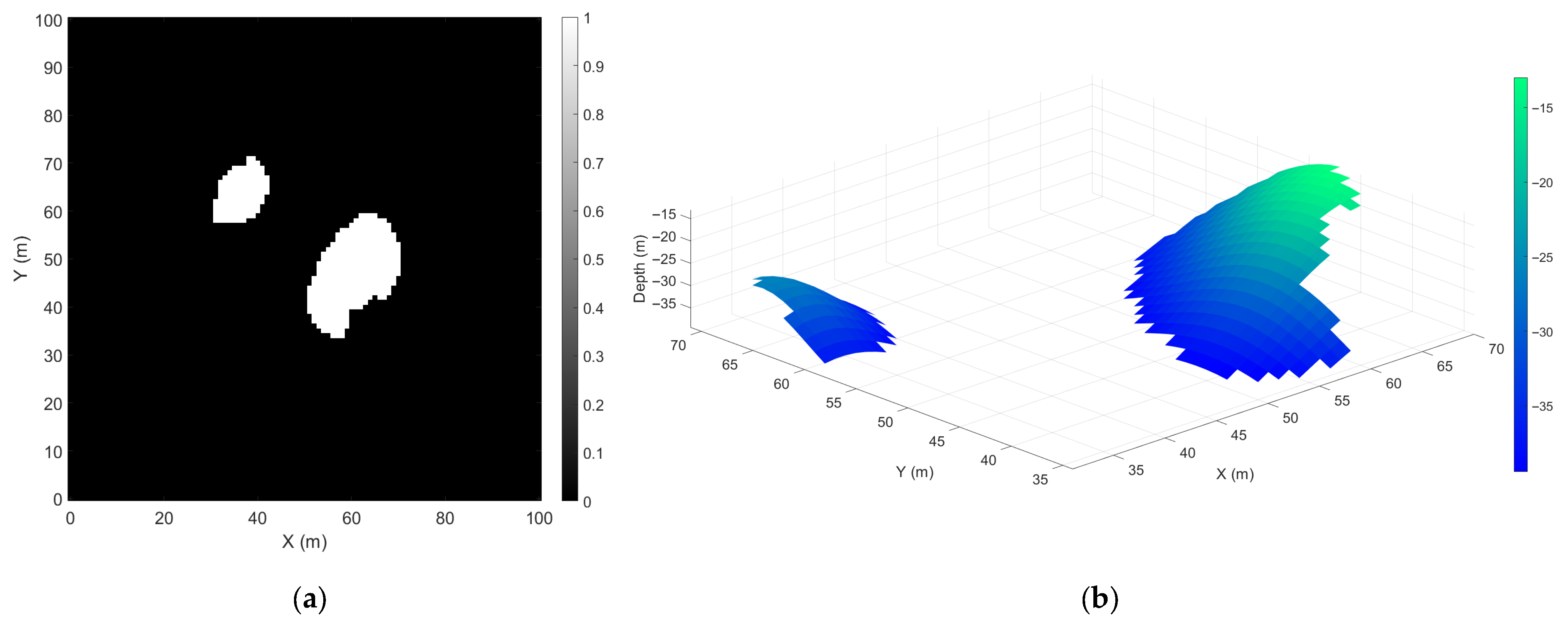
At the beginning of each cycle at time t , every AUV scans the seafloor using its onboard camera. Any grid cell within the FoV that maintains an unoccluded LoS to the AUV is classified as visible [see Figure 4]. The coverage map C t is then updated by setting C t ( x a , y b ) = 1 for each visible cell, and the corresponding elevation estimate T ^ t ( x a , y b ) is updated accordingly, as illustrated in Figure 5a,b.
Using this updated coverage map, the frontier set is extracted and defined as the set of uncovered boundary cells that share a four-neighborhood with at least one covered cell [50]:
F t = ( x a , y b ) G   C t x a , y b = 0   and     4 -nbr ( x a , y b )   with   C t x a , y b = 1 } .
These frontier cells represent locations where new information can be obtained, as depicted in Figure 6.
For each AUV i , at time t , let ξ i ( t ) denotes an indicator variable that determines whether the AUV requires a goal assignment. It is defined as
ξ i t = 1 ,   I f   n o   g o a l   i s   l a t c h e d   o r   μ i ( t ) ϵ 0 ,   Otherwise , ,
where μ i ( t ) represents the 3D Euclidean distance from the current position of AUV i , p i ( t ) , and its assigned goal, while ϵ denotes the goal-reaching tolerance. Only AUVs with ξ i t = 1 request a new goal assignment.
For each AUV requiring a new goal, a distinct frontier goal is assigned using a greedy nearest-neighbor strategy subject to spacing constraints. Let the current set of N frontiers at time t , indexed by n = 1 , , N , be defined as
F ( t ) = { f 1 ,   ,   f N } ,               f n = ( x a n , y b n ) .
For AUV i located at the horizontal position ( x i ,   y i ), the distance to a frontier f n is given by
κ i , n = ( x i x a n ) 2 + ( y i y b n ) 2 .
Let G ( t ) denotes the set of goals already allocated to other AUVs during the current cycle. The assigned goal g i for AUV i is determined as
g i arg min f n F ( t ) G ( t ) κ i , n ,
subject to the spacing constraint
f n g j ε safe ,         g j G t .
Here, ε safe denotes the minimum allowable separation distance as in (5) to promote safe assignment. After each assignment, the newly selected goal g i is added to the set G ( t ) . Consequently, the latched goal set for all AUVs at time t is expressed as
G ( t ) = g 1 ,   ,   g M ,         g i g j ε safe ,     i j .
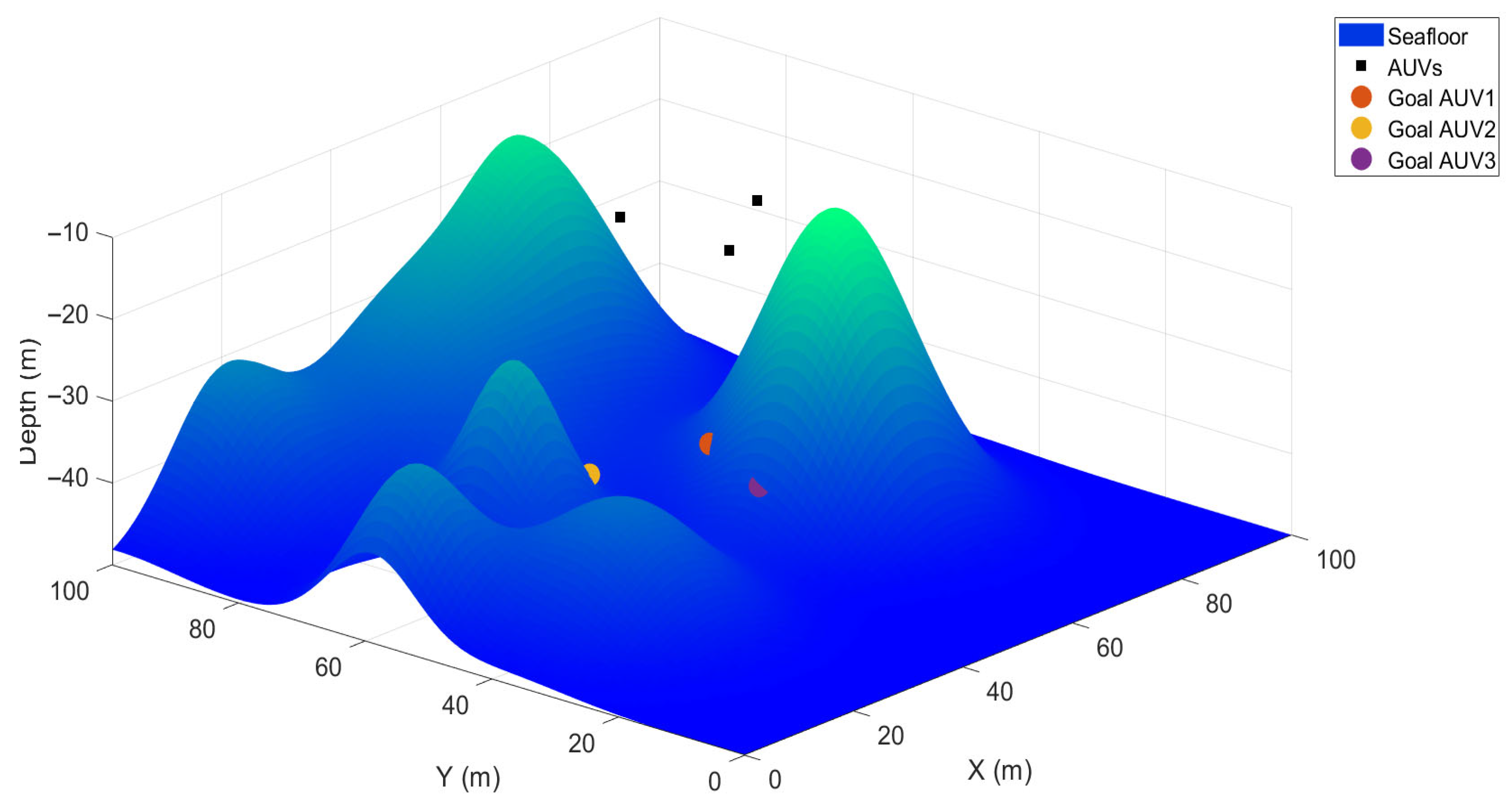
For each selected horizontal goal g i = ( x i , goal , y i , goal ) , the seafloor height T t ~ ( g i ) at that point is estimated from the nearest known cell in the current elevation map T ^ t . If several cells are equally near, the one with the highest elevation is used to provide the conservative estimate. This approximation relies on the assumption that the seafloor surface is locally continuous and varies smoothly at the grid resolution used, which makes the nearest covered neighbor cell a reasonable estimate of the unknown elevation. In addition, the enforced minimum clearance h safe further ensures reliability even in the presence of moderate local discontinuities. Let ( x a near , y b near ) denote the nearest cell to ( x i , goal , y i , goal ) in terms of Euclidean distance. Then, the seafloor height at the goal is computed as
T t ~ g i = T ^ t x a near , y b near ,
which provides the estimated depth of the goal, as illustrated in Figure 7.
Let the desired footprint radius be defined as
ρ des = η R sin ( θ / 2 ) ,   η 0,1 ,
and introduce the safe viewing offset
ζ = m a x { h safe , ρ des tan ( θ / 2 ) } .
In (19), the maximum operator ensures that the viewing offset is assigned to the greater of the minimum safety clearance and the desired height, hence ensuring a safe selection above the seafloor. The computed goal depth is then given by
z i , goal = T t ~ ( g i ) + ζ .
In this design, η is a parameter that scales the desired footprint radius relative to the sensor’s maximum possible footprint.
Equation (20) defines a viewpoint for each goal such that the resulting footprint remains informative, within sensor range, and at a safe distance from the terrain. The final set of 3D goal positions for all AUVs at time t is expressed as [see Figure 8]
W ( t ) = { ω 1 , , ω M } ,   ω i = ( x i , goal , y i , goal , z i , goal ) .
Each goal ω i is latched to its corresponding AUV, and an AUV only requests a new goal once it has arrived within the tolerance ϵ of its currently latched goal.
Given a latched goal ω i , each AUV solves a short-horizon MPC problem to track the goal while maintaining a safe clearance from the current elevation estimate T ^ t . For this purpose, we discretize the continuous-time kinematic model in (2) to obtain the discrete-time prediction model. With the state vector X i = [ x i , y i , z i , ψ i ] T , control input U i = [ u i , w i , r i ] T , and sampling period δ , the discrete-time prediction model is given by
X i k + 1 = x i k + δ u i k cos ψ i [ k ] y i k + δ u i k sin ψ i [ k ] z i k + δ w i k ψ i k + δ r i k ,
U i k = u i k w i k r i k ,
with the following input bounds enforced at each step k = 0 , H 1 :
0 u i k u max ,   w min w i k w max ,   r max r i k r max ,
where H denotes the prediction horizon.
Given the position vector p i k = [ x i k , y i k , z i k ] T of AUV i , we formulate the MPC cost function as:
L X i k , U i k = p i k ω i T Q p p i k ω i + U i k T S   U i k + γ [ T ^ t ( x i k , y i k ) + h safe z i k ) ] + 2 ,
where [ c ] + = max   { 0 , c } , Q p is a diagonal weight penalizing 3D position tracking errors, S weights control effort, and the third term softly enforce a terrain-clearance constraint.
At each cycle, for each AUV i , we solve the following finite-horizon optimization problem:
min { u i k } k = 0 H 1 k = 0 H 1 L X i k , U i k ,
subject to constraints (3) and (5), discrete dynamics (22), and the input bounds specified in (24). After solving, we apply the first control U i 1 , update the vehicle state, and repeat this process until a reach tolerance ϵ is satisfied. This sense-assign-track cycle is repeated until the coverage criterion Q ( t ) λ target is achieved.

3. Results and Discussion

This section presents simulation results obtained in MATLAB R2022b to evaluate the performance of the proposed occlusion-aware multi-AUV sweep coverage method. The method is tested across multiple seafloor profiles to assess its adaptability to varying terrain conditions. In all scenarios, the algorithm successfully achieves the specified target coverage, while the generated AUV trajectories maintain safe clearance from the seafloor. The results include final coverage maps and vehicle paths, showing that the planned motions consistently satisfy safety constraints. To provide a comparative assessment, the proposed method is benchmarked against a commonly used sweep coverage strategy, with performance is evaluated in terms of hitting time, achieved coverage, path length, and terrain clearance.
The proposed method is implemented using the following system parameters: M = 3 , σ = 1 , δ = 1   s , λ target = 99.5 % , θ = 60 ° , R = 30   m , h safe = 5   m , Z max = 5   m , Z min = 30   m , H = 3 , u max = 2   m / s , w min = 0.5   m / s , w max = 0.5   m / s , r max = π / 4   rad / s , ϵ = 1 m, and ε safe = 5 m. These parameters were selected after preliminary testing to provide a practical balance between safety, trajectory smoothness, and computational efficiency in the simulated environments. The chosen values demonstrated consistent stability and satisfactory performance across different seafloor profiles, ensuring sufficient terrain clearance, smooth trajectory generation, and reliable inter-vehicle separation. A detailed analysis of how variations in these parameters influence coverage quality, mission time, path efficiency, and overall operational safety is beyond the current scope and will be considered in future work.
Three AUVs are initialized in a circular formation of radius 10 m centered at the midpoint of the region of interest A . Each vehicle begins at a depth of 10 m, from which the proposed method determines subsequent safe operating depths. The seafloor is modeled as a 2.5D elevation map over the domain A = 0 ,   100 × 0 ,   100 m. A flat baseline depth of   50 m is perturbed by a random number of Gaussian hills with amplitudes ranging from 5 m and 20 m and spreads between 5 m and 15 m. This produces uneven seafloors with varying elevation and spatial distribution of features, ensuring diverse coverage conditions. Two representative seafloors, shown in Figure 9a,b, are randomly selected from this procedure for evaluation. The differences between the two arise from variations in the number and height of hills, the characteristics of the peaks, and the irregular placement of terrain features across the domain. These two environments serve as test cases for assessing the adaptability of the proposed method under different seafloor conditions.
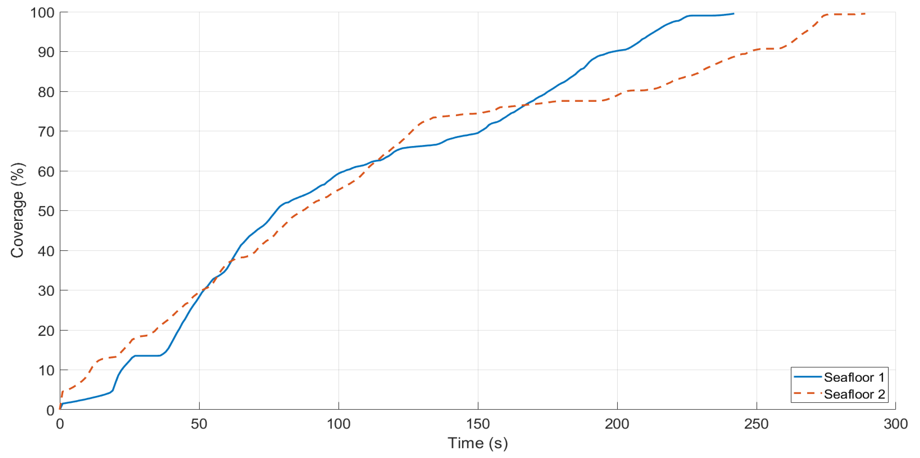
The proposed algorithm achieves the target coverage on both seafloors despite their different elevation characteristics. Figure 10 shows coverage progression for both cases. On Seafloor 1 [see Figure 9a], characterized by broader hills, coverage increases smoothly and reaches 99.5% in about 245 s. On Seafloor 2 [refer to Figure 9b], which features higher and sharper peaks, coverage progresses more slowly and completes in about 290 s, as the AUVs must adapt more frequently to maintain LoS visibility and safe clearance.
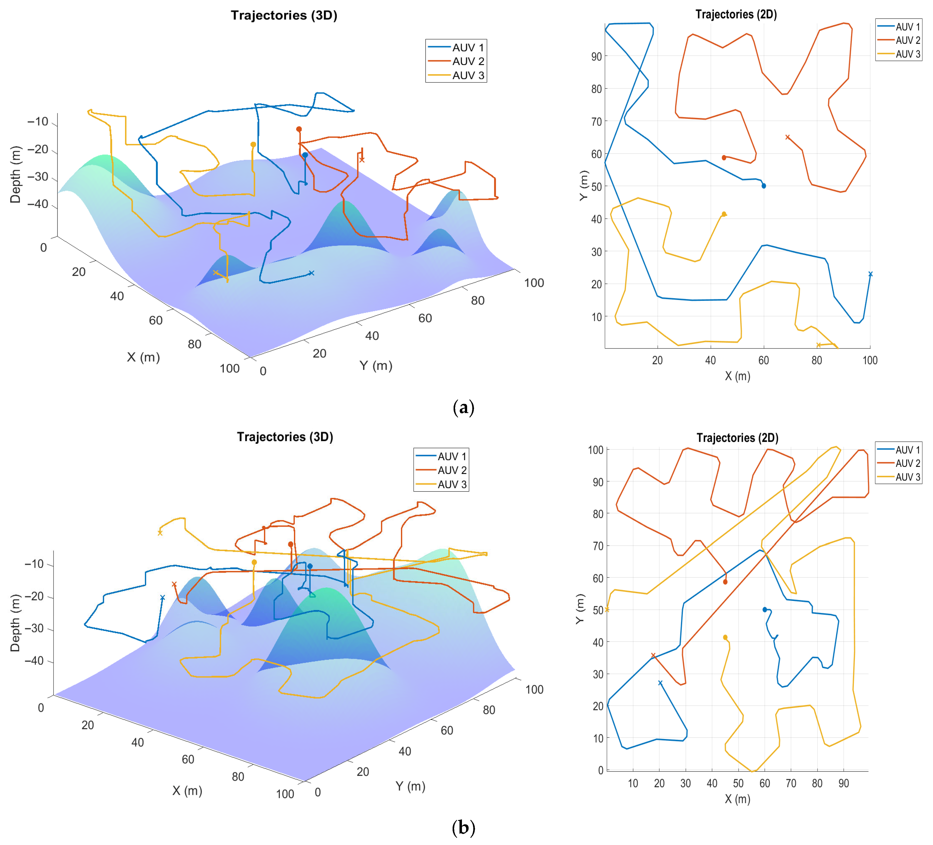
The corresponding trajectories for both cases, illustrated in Figure 11a,b, show that the vehicles are efficiently distributed across the domain, avoid unnecessary overlap, and maintain the required separation. Longer detours are observed on Seafloor 2 due to steep terrain. The estimated terrain maps for both cases, shown in Figure 12a,b, closely match the ground truth, capturing the main peaks and valleys with sufficient accuracy. Overall, these results demonstrate the effectiveness of the proposed method in achieving reliable coverage and safe operation across both seafloors.
To further evaluate its performance, the proposed method is compared with a widely used classical baseline. Specifically, it is benchmarked against the lawnmower coverage pattern, which is a standard reference in coverage path planning tasks [28,51,52,53]. The choice is justified since the lawnmower strategy provides a deterministic and well-understood baseline, allowing performance gains to be attributed directly to the proposed algorithm. Moreover, it was shown in [54] that, on flat terrains, the lawnmower strategy is asymptotically optimal, meaning that as the size of the investigated region grows, it provides a time optimal complete sweep coverage by a team of collaborating autonomous vehicles. Although more advanced coverage methods exist, many depend on environment-specific modeling, proprietary submodules, or computational frameworks that are not directly comparable to the conditions considered in this study [55,56,57,58]. Using the lawnmower baseline therefore ensures a fair and reproducible comparison and highlights the advantages of the proposed method in handling uneven seafloor conditions, where fixed-pattern strategies provide a meaningful contrast.
Both methods use the same sensor model and environment configuration. In the baseline, the domain is partitioned into vertical strips traversed in boustrophedon order, and strips are assigned to the three AUVs in a round-robin manner. Vehicles follow waypoints at a fixed survey depth of z survey = 30 m and forward speed v survey = 2 m/s. We evaluate two lawnmower settings that differed only in strip spacing: a baseline spacing with 10% overlap and a shorter spacing obtained by scaling the baseline strip width by 0.60 to increase sampling density and mitigate occlusion effects. Strip width is derived from the sensor footprint at the survey altitude, with ρ survey = min { h s u r v e y , R c o s ( θ / 2 ) }   t a n ( θ / 2 ) and spacing 2 ρ survey ( 1 o v e r l a p ) . Runs terminate upon reaching λ target or when no further increase in coverage is observed. Across all methods, we record coverage over time, path length per AUV, average clearance, and minimum clearance versus time, enabling direct comparison of hitting time, coverage, efficiency, and safety.
On the seafloor shown in Figure 13, the proposed method outperforms the lawnmower baselines across all evaluation metrics. It achieves 99.5% coverage within 235 s, while the 10% overlap lawnmower stops increasing at 66.7% after 302 s, and the reduced-spacing variant attains only 79.2% after 406 s [see Figure 14]. These results highlight the persistent difficulty of fixed strip patterns in handling occlusions, even when sampling density is increased, whereas the proposed method effectively adapts its trajectories to close gaps and ensure the completion of the desired coverage.
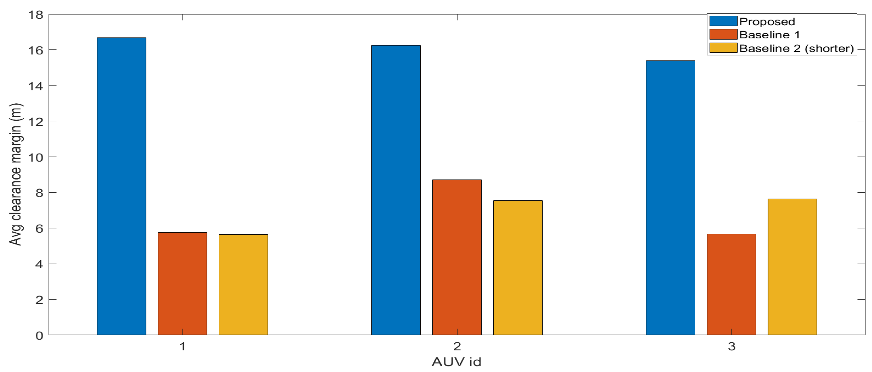
Trajectory plots in Figure 15 further illustrate this distinction. The proposed method allows the AUVs to distribute themselves adaptively across the domain and adjust their depths in response to local terrain, in contrast to the rigid strip following behavior of the lawnmower baselines. The clearance results in Figure 16 and Figure 17 reinforce this observation, showing that the proposed method consistently maintains higher minimum clearance margins and greater average clearance, whereas both lawnmower settings frequently violate safety constraints.
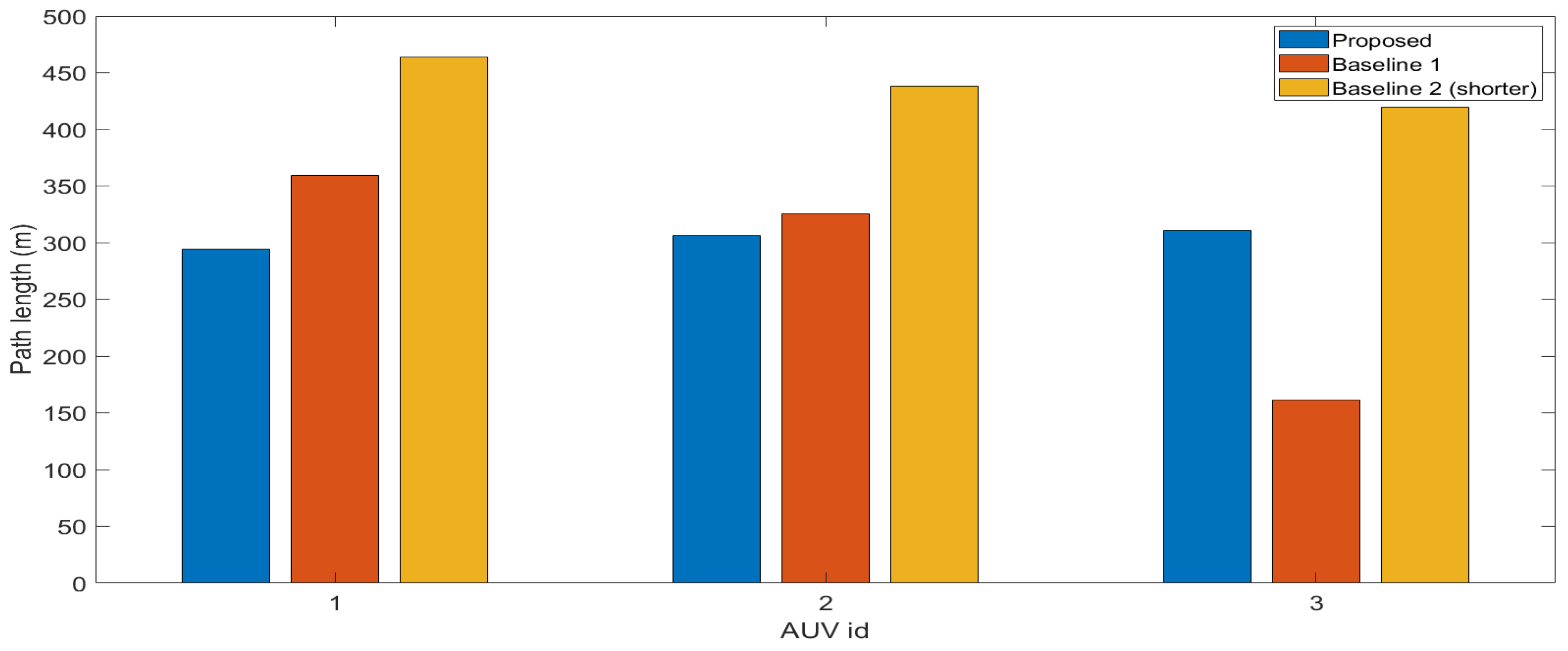
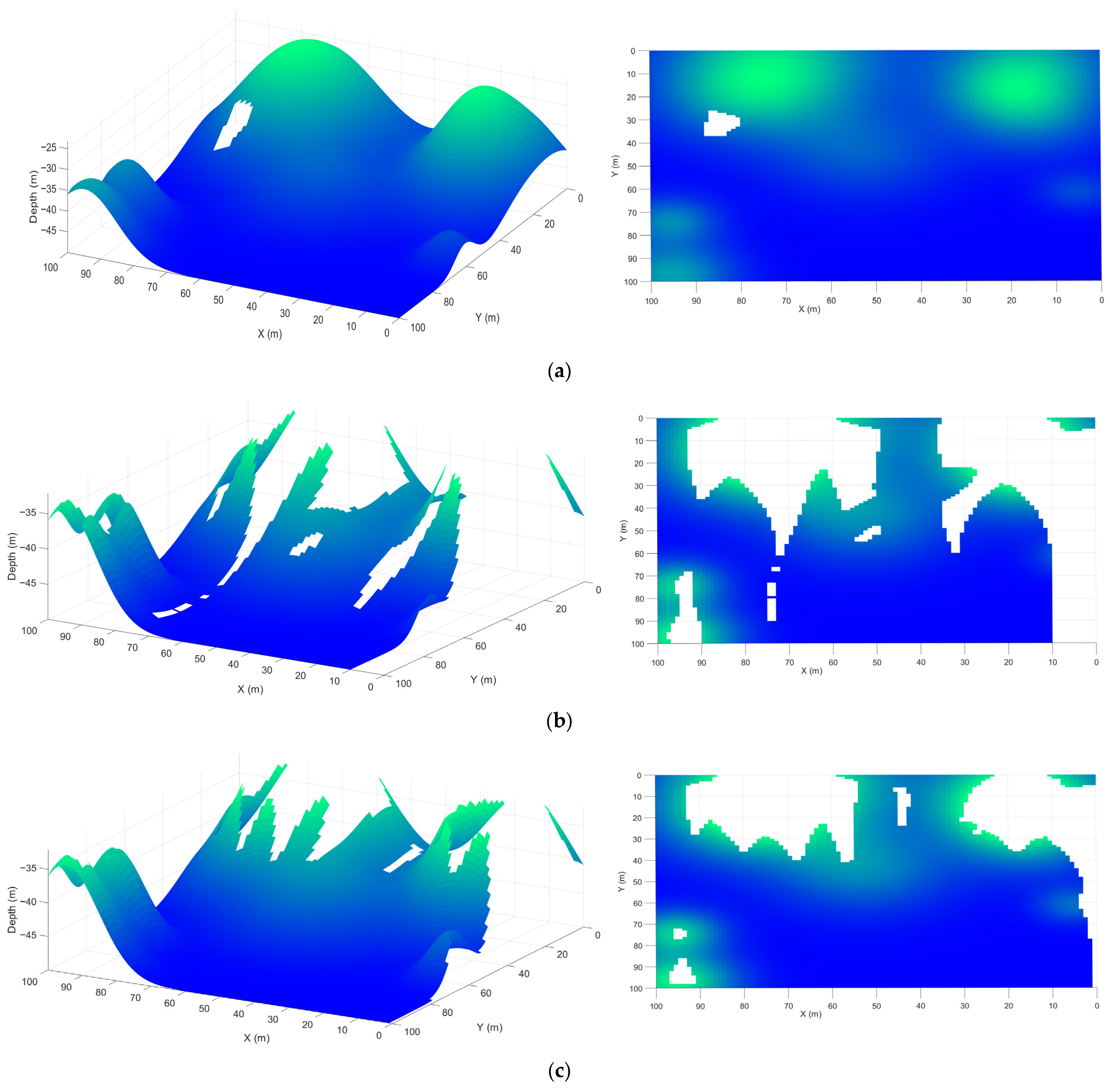
Path length comparisons in Figure 18 confirm the efficiency of the proposed method, which achieves the desired coverage with shorter trajectories per AUV than either lawnmower variants. Although the reduced spacing lawnmower produces significantly longer paths, it still fails to achieve the target coverage. This demonstrates that denser sampling alone is insufficient without terrain-adaptive planning. This is evident from the elevation reconstructions in Figure 19a–c, where the proposed method produces a reliable seafloor map, while both lawnmower baselines leave extensive unobserved regions.
Overall, the results demonstrate that the proposed method achieves higher coverage in less time while maintaining safer clearance and more efficient trajectories. By contrast, the lawnmower baselines are constrained by occlusion and repetitive paths. These limitations highlight the advantage of online planning in complex underwater environments.

4. Conclusions

This work presents an occlusion-aware multi-AUV sweep coverage method for unknown and uneven seafloor environments. By integrating frontier-based exploration with MPC trajectory planning under an occlusion-aware sensor model and safe constraints, the approach adaptively guides multiple vehicles to achieve reliable coverage while avoiding collisions and maintaining minimum clearance above the terrain. Simulation results show that the proposed method consistently reaches the target coverage in shorter times with safer and more efficient trajectories compared to classical lawnmower baselines. Fixed-strip strategies, even with denser sampling, struggle to handle occlusions, leading to incomplete coverage, longer paths, and frequent clearance violations. These findings highlight the importance of adaptive and online planning in challenging underwater conditions.
Future research will focus on extending the proposed framework in several directions. First, scalability will be examined by testing larger AUV teams, and adaptive parameter adjustments will be investigated to enhance flexibility across varying underwater environments. Furthermore, the robustness of the framework under sensing and localization uncertainties will be analyzed, alongside quantitative evaluations to assess the consistency and stability of its performance under diverse operating conditions. Finally, experimental validation using real or laboratory-scale AUVs will be conducted to verify the framework’s practicality under realistic hydrodynamics and sensing conditions.

Author Contributions

Conceptualization, T.S.A. and A.V.S.; methodology, T.S.A. and A.V.S.; software, T.S.A.; validation, T.S.A.; formal analysis, T.S.A.; investigation, T.S.A.; resources, T.S.A.; data curation, T.S.A.; writing—original draft preparation, T.S.A.; writing—review and editing, A.V.S.; visualization, T.S.A.; supervision, A.V.S.; project administration, A.V.S.; funding acquisition, A.V.S. All authors have read and agreed to the published version of the manuscript.

Funding

This work was supported by the Australian Research Council by the grant DP190102501.

Data Availability Statement

The data supporting this study are available from the corresponding author upon reasonable request, as they are not publicly accessible due to privacy restrictions.

Conflicts of Interest

The authors declare no conflicts of interest.

Abbreviations

The following abbreviations are used in this manuscript:
AUVsAutonomous underwater vehicles
FoVField of View
MPCModel Predictive Control
LoSLine of Sight
CPPCoverage Path Planning

References

  1. Liu, Z.; Meng, X.; Liu, Y.; Yang, Y.; Wang, Y. AUV-Aided Hybrid Data Collection Scheme Based on Value of Information for Internet of Underwater Things. IEEE Internet Things J. 2022, 9, 6944–6955. [Google Scholar] [CrossRef]
  2. Jahanbakht, M.; Xiang, W.; Hanzo, L.; Azghadi, M.R. Internet of Underwater Things and Big Marine Data Analytics—A Comprehensive Survey. IEEE Commun. Surv. Tutor. 2021, 23, 904–956. [Google Scholar] [CrossRef]
  3. Huang, H.; Wen, X.; Niu, M.; Miah, M.S.; Wang, H.; Gao, T. Multi-Objective Path Planning of Autonomous Underwater Vehicles Driven by Manta Ray Foraging. J. Mar. Sci. Eng. 2024, 12, 88. [Google Scholar] [CrossRef]
  4. Kundavaram, R.R.; Onteddu, A.R.; Devarapu, K.; Narsina, D.; Nizamuddin, M. Advances in Autonomous Robotics for Environmental Cleanup and Hazardous Waste Management. Asia Pac. J. Energy Environ. 2025, 12, 1–16. [Google Scholar] [CrossRef]
  5. Kemna, S.; Hamilton, M.J.; Hughes, D.T.; LePage, K.D. Adaptive Autonomous Underwater Vehicles for Littoral Surveillance. Intell. Serv. Robot. 2011, 4, 245–258. [Google Scholar] [CrossRef]
  6. Chen, Z.; Zhang, D.; Wang, C.; Sha, Q. Hybrid Form of Differential Evolutionary and Gray Wolf Algorithm for Multi-AUV Task Allocation in Target Search. Electronics 2023, 12, 4575. [Google Scholar] [CrossRef]
  7. Almuzaini, T.S.; Savkin, A.V. Multi-Auv Path Planning for Underwater Video Surveillance Over an Uneven Seafloor. In Proceedings of the 2025 17th International Conference on Computer and Automation Engineering (ICCAE), Perth, Australia, 20–22 March 2025; pp. 557–561. [Google Scholar]
  8. Bianchi, C.N.; Azzola, A.; Cocito, S.; Morri, C.; Oprandi, A.; Peirano, A.; Sgorbini, S.; Montefalcone, M. Biodiversity Monitoring in Mediterranean Marine Protected Areas: Scientific and Methodological Challenges. Diversity 2022, 14, 43. [Google Scholar] [CrossRef]
  9. Di Ciaccio, F.; Troisi, S. Monitoring Marine Environments with Autonomous Underwater Vehicles: A Bibliometric Analysis. Results Eng. 2021, 9, 100205. [Google Scholar] [CrossRef]
  10. Silarski, M.; Sibczyński, P.; Bezshyyko, O.; Kapłon, Ł.; Kumar, V.; Niedźwiecki, S.; Nowakowski, M.; Moskal, P.; Sharma, S.; Sobczuk, F. Monte Carlo Simulations of the Underwater Detection of Illicit War Remnants with Neutron-Based Sensors. Eur. Phys. J. Plus 2023, 138, 751. [Google Scholar] [CrossRef]
  11. Li, D.; Wang, P.; Du, L. Path Planning Technologies for Autonomous Underwater Vehicles-A Review. IEEE Access 2019, 7, 9745–9768. [Google Scholar] [CrossRef]
  12. Murad, M.F.A.B.M.; Samah, M.I.B.; Ismail, Z.H.; Sammut, K. Surveillance of Coral Reef Development Using an Autonomous Underwater Vehicle. In Proceedings of the 2016 IEEE/OES Autonomous Underwater Vehicles (AUV), Tokyo, Japan, 6–9 November 2016; pp. 14–19. [Google Scholar]
  13. Ramírez, I.S.; Bernalte Sánchez, P.J.; Papaelias, M.; Márquez, F.P.G. Autonomous Underwater Vehicles and Field of View in Underwater Operations. J. Mar. Sci. Eng. 2021, 9, 277. [Google Scholar] [CrossRef]
  14. Nam, L.H.; Huang, L.; Li, X.J.; Xu, J.F. An Approach for Coverage Path Planning for UAVs. In Proceedings of the 2016 IEEE 14th International Workshop on Advanced Motion Control (AMC), Auckland, New Zealand, 22–24 April 2016; pp. 411–416. [Google Scholar]
  15. Tiwari, S. Mosaicking of the Ocean Floor in the Presence of Three-Dimensional Occlusions in Visual and Side-Scan Sonar Images. In Proceedings of the Symposium on Autonomous Underwater Vehicle Technology, Monterey, CA, USA, 2–6 June 1996; pp. 308–314. [Google Scholar]
  16. Zacchini, L.; Franchi, M.; Bucci, A.; Secciani, N.; Ridolfi, A. Randomized MPC for View Planning in AUV Seabed Inspections. In Proceedings of the OCEANS 2021: San Diego—Porto, San Diego, CA, USA, 20–23 September 2021; pp. 1–6. [Google Scholar]
  17. Zhang, J.; Zhou, W.; Deng, X.; Yang, S.; Yang, C.; Yin, H. Optimization of Adaptive Observation Strategies for Multi-AUVs in Complex Marine Environments Using Deep Reinforcement Learning. J. Mar. Sci. Eng. 2025, 13, 865. [Google Scholar] [CrossRef]
  18. Cai, K.; Zhang, G.; Sun, Y.; Ding, G.; Xu, F. Multi Autonomous Underwater Vehicle (AUV) Distributed Collaborative Search Method Based on a Fuzzy Clustering Map and Policy Iteration. J. Mar. Sci. Eng. 2024, 12, 1521. [Google Scholar] [CrossRef]
  19. Cao, X.; Yu, A. Multi-AUV Cooperative Target Search Algorithm in 3-D Underwater Workspace. J. Navig. 2017, 70, 1293–1311. [Google Scholar] [CrossRef]
  20. Choset, H. Coverage for Robotics—A Survey of Recent Results. Ann. Math. Artif. Intell. 2001, 31, 113–126. [Google Scholar] [CrossRef]
  21. Hameed, I.A. Intelligent Coverage Path Planning for Agricultural Robots and Autonomous Machines on Three-Dimensional Terrain. J. Intell. Robot. Syst. 2014, 74, 965–983. [Google Scholar] [CrossRef]
  22. Galceran, E.; Campos, R.; Palomeras, N.; Ribas, D.; Carreras, M.; Ridao, P. Coverage Path Planning with Real-Time Replanning and Surface Reconstruction for Inspection of Three-Dimensional Underwater Structures Using Autonomous Underwater Vehicles. J. Field Robot. 2015, 32, 952–983. [Google Scholar] [CrossRef]
  23. Hameed, I.A. Coverage Path Planning Software for Autonomous Robotic Lawn Mower Using Dubins’ Curve. In Proceedings of the 2017 IEEE International Conference on Real-time Computing and Robotics (RCAR), Okinawa, Japan, 14–18 July 2017; pp. 517–522. [Google Scholar]
  24. Basilico, N.; Carpin, S. Deploying Teams of Heterogeneous UAVs in Cooperative Two-Level Surveillance Missions. In Proceedings of the 2015 IEEE/RSJ International Conference on Intelligent Robots and Systems (IROS), Hamburg, Germany, 28 September–2 October 2015; pp. 610–615. [Google Scholar]
  25. Tan, C.S.; Mohd-Mokhtar, R.; Arshad, M.R. A Comprehensive Review of Coverage Path Planning in Robotics Using Classical and Heuristic Algorithms. IEEE Access 2021, 9, 119310–119342. [Google Scholar] [CrossRef]
  26. Ghaddar, A.; Merei, A.; Natalizio, E. PPS: Energy-Aware Grid-Based Coverage Path Planning for UAVs Using Area Partitioning in the Presence of NFZs. Sensors 2020, 20, 3742. [Google Scholar] [CrossRef]
  27. Xing, S.; Wang, R.; Huang, G. Area Decomposition Algorithm for Large Region Maritime Search. IEEE Access 2020, 8, 205788–205797. [Google Scholar] [CrossRef]
  28. Choset Howie and Pignon, P. Coverage Path Planning: The Boustrophedon Cellular Decomposition. In Field and Service Robotics; Zelinsky, A., Ed.; Springer: London, UK, 1998; pp. 203–209. [Google Scholar]
  29. Bircher, A.; Kamel, M.; Alexis, K.; Oleynikova, H.; Siegwart, R. Receding Horizon “Next-Best-View” Planner for 3D Exploration. In Proceedings of the 2016 IEEE International Conference on Robotics and Automation (ICRA), Stockholm, Sweden, 16–21 May 2016; pp. 1462–1468. [Google Scholar]
  30. Selin, M.; Tiger, M.; Duberg, D.; Heintz, F.; Jensfelt, P. Efficient Autonomous Exploration Planning of Large-Scale 3-D Environments. IEEE Robot. Autom. Lett. 2019, 4, 1699–1706. [Google Scholar] [CrossRef]
  31. Vidal, E.; Palomeras, N.; Istenič, K.; Gracias, N.; Carreras, M. Multisensor Online 3D View Planning for Autonomous Underwater Exploration. J. Field Robot. 2020, 37, 1123–1147. [Google Scholar] [CrossRef]
  32. Yamauchi, B. A Frontier-Based Approach for Autonomous Exploration. In Proceedings of the 1997 IEEE International Symposium on Computational Intelligence in Robotics and Automation CIRA’97. “Towards New Computational Principles for Robotics and Automation”, Monterey, CA, USA, 10–11 July 1997; pp. 146–151. [Google Scholar]
  33. Quin, P.; Alempijevic, A.; Paul, G.; Liu, D. Expanding Wavefront Frontier Detection: An Approach for Efficiently Detecting Frontier Cells. In Proceedings of the Australasian Conference on Robotics and Automation, ACRA, Melbourne, Australia, 2–4 December 2014. [Google Scholar]
  34. Quin, P.; Nguyen, D.D.K.; Vu, T.L.; Alempijevic, A.; Paul, G. Approaches for Efficiently Detecting Frontier Cells in Robotics Exploration. Front. Robot. AI 2021, 8, 616470. [Google Scholar] [CrossRef]
  35. Wang, R.; Zhang, J.; Lyu, M.; Yan, C.; Chen, Y. An Improved Frontier-Based Robot Exploration Strategy Combined with Deep Reinforcement Learning. Robot. Auton. Syst. 2024, 181, 104783. [Google Scholar] [CrossRef]
  36. Vidal, E.; Palomeras, N.; Istenič, K.; Hernández, J.D.; Carreras, M. Two-Dimensional Frontier-Based Viewpoint Generation for Exploring and Mapping Underwater Environments. Sensors 2019, 19, 1460. [Google Scholar] [CrossRef]
  37. Mayne, D.Q.; Rawlings, J.B.; Rao, C.V.; Scokaert, P.O.M. Constrained Model Predictive Control: Stability and Optimality. Automatica 2000, 36, 789–814. [Google Scholar] [CrossRef]
  38. Zhang, Y.; Liu, X.; Luo, M.; Yang, C. MPC-Based 3-D Trajectory Tracking for an Autonomous Underwater Vehicle with Constraints in Complex Ocean Environments. Ocean Eng. 2019, 189, 106309. [Google Scholar] [CrossRef]
  39. Gong, P.; Yan, Z.; Zhang, W.; Tang, J. Lyapunov-Based Model Predictive Control Trajectory Tracking for an Autonomous Underwater Vehicle with External Disturbances. Ocean Eng. 2021, 232, 109010. [Google Scholar] [CrossRef]
  40. Chen, Y.; Bian, Y. Tube-Based Event-Triggered Path Tracking for AUV against Disturbances and Parametric Uncertainties. Electronics 2023, 12, 4248. [Google Scholar] [CrossRef]
  41. Xu, F.; Zhang, L.; Zhong, J. Three-Dimensional Path Tracking of Over-Actuated AUVs Based on MPC and Variable Universe S-Plane Algorithms. J. Mar. Sci. Eng. 2024, 12, 418. [Google Scholar] [CrossRef]
  42. Eskandari, M.; Savkin, A. V Kinodynamic Motion Model-Based MPC Path Planning and Localization for Autonomous AUV Teams in Deep Ocean Exploration. In Proceedings of the 2025 33rd Mediterranean Conference on Control and Automation (MED), Tangier, Morocco, 10–13 June 2025; pp. 162–167. [Google Scholar]
  43. Gu, J.; Cao, Q. Path Planning for Mobile Robot in a 2.5-dimensional Grid-based Map. Ind. Robot Int. J. Robot. Res. Appl. 2011, 38, 315–321. [Google Scholar] [CrossRef]
  44. Liu, Y.; Sun, Y.; Li, B.; Wang, X.; Yang, L. Experimental Analysis of Deep-Sea AUV Based on Multi-Sensor Integrated Navigation and Positioning. Remote Sens. 2024, 16, 199. [Google Scholar] [CrossRef]
  45. Savkin, A.V.; Verma, S.C.; Anstee, S. Optimal Navigation of an Unmanned Surface Vehicle and an Autonomous Underwater Vehicle Collaborating for Reliable Acoustic Communication with Collision Avoidance. Drones 2022, 6, 27. [Google Scholar] [CrossRef]
  46. Wang, C.; Savkin, A.V.; Garratt, M. A Strategy for Safe 3D Navigation of Non-Holonomic Robots among Moving Obstacles. Robotica 2018, 36, 275–297. [Google Scholar] [CrossRef]
  47. Savkin, A.V.; Huang, H. Proactive Deployment of Aerial Drones for Coverage over Very Uneven Terrains: A Version of the 3D Art Gallery Problem. Sensors 2019, 19, 1438. [Google Scholar] [CrossRef]
  48. Huang, H.; Savkin, A.V.; Ni, W. Online UAV Trajectory Planning for Covert Video Surveillance of Mobile Targets. IEEE Trans. Autom. Sci. Eng. 2022, 19, 735–746. [Google Scholar] [CrossRef]
  49. Jiang, W.; Yang, X.; Tong, F.; Yang, Y.; Zhou, T. A Low-Complexity Underwater Acoustic Coherent Communication System for Small AUV. Remote Sens. 2022, 14, 3405. [Google Scholar] [CrossRef]
  50. Ericson, L.; Jensfelt, P. Beyond the Frontier: Predicting Unseen Walls from Occupancy Grids by Learning From Floor Plans. IEEE Robot. Autom. Lett. 2024, 9, 6832–6839. [Google Scholar] [CrossRef]
  51. Shi, J.; Zhou, M. A Data-Driven Intermittent Online Coverage Path Planning Method for AUV-Based Bathymetric Mapping. Appl. Sci. 2020, 10, 6688. [Google Scholar] [CrossRef]
  52. Özkahraman, Ö.; Ögren, P. Efficient Navigation Aware Seabed Coverage Using AUVs. In Proceedings of the 2021 IEEE International Symposium on Safety, Security, and Rescue Robotics (SSRR), New York, NY, USA, 25–27 October 2021; pp. 63–70. [Google Scholar]
  53. Zacchini, L.; Franchi, M.; Ridolfi, A. Sensor-Driven Autonomous Underwater Inspections: A Receding-Horizon RRT-Based View Planning Solution for AUVs. J. Field Robot. 2022, 39, 499–527. [Google Scholar] [CrossRef]
  54. Savkin, A.V.; Huang, H. Asymptotically Optimal Path Planning for Ground Surveillance by a Team of UAVs. IEEE Syst. J. 2022, 16, 3446–3449. [Google Scholar] [CrossRef]
  55. Cai, C.; Chen, J.; Yan, Q.; Liu, F. A Multi-Robot Coverage Path Planning Method for Maritime Search and Rescue Using Multiple AUVs. Remote Sens. 2023, 15, 93. [Google Scholar] [CrossRef]
  56. Mu, X.; Gao, W. Coverage Path Planning for Multi-AUV Considering Ocean Currents and Sonar Performance. Front. Mar. Sci. 2025, 11, 1483122. [Google Scholar] [CrossRef]
  57. Xie, Y.; Hui, W.; Zhou, D.; Shi, H. Three-Dimensional Coverage Path Planning for Cooperative Autonomous Underwater Vehicles: A Swarm Migration Genetic Algorithm Approach. J. Mar. Sci. Eng. 2024, 12, 1366. [Google Scholar] [CrossRef]
  58. Li, Y.; Ma, M.; Cao, J.; Luo, G.; Wang, D.; Chen, W. A Method for Multi-AUV Cooperative Area Search in Unknown Environment Based on Reinforcement Learning. J. Mar. Sci. Eng. 2024, 12, 1194. [Google Scholar] [CrossRef]
Figure 1. 2.5D seafloor discretized into grid G with resolution σ = 1 m. (a) 3D surface with grid G overlaid; (b) plan-view (2D) height map.
Drones 09 00735 g001
Figure 2. Conical FoV projected onto the ground plane with θ = 60 ° and range R = 20   m .
Drones 09 00735 g002
Figure 3. Illustration of LoS occlusion between the AUV and a grid cell within the camera’s FoV. The red solid line indicates the LoS from the AUV to the selected grid cell.
Drones 09 00735 g003
Figure 4. Covere. seafloor regions after AUV scanning, outlined in white with current AUV positions shown as red dots. (a) 2D view; (b,c) 3D views.
Drones 09 00735 g004
Figure 5. Results after the initial scan. (a) coverage map showing visible cells; (b) estimated elevation map based on local sensing.
Drones 09 00735 g005
Figure 6. Frontier Cells shown as green dots on the coverage map.
Drones 09 00735 g006
Figure 7. Assigned frontiers for each AUV on the seafloor with corresponding depth estimates.
Drones 09 00735 g007
Figure 8. The 3D latched goals assigned to each AUV.
Drones 09 00735 g008
Figure 9. Underwater regions considered. (a) Seafloor 1; (b) Seafloor 2.
Drones 09 00735 g009aDrones 09 00735 g009b
Figure 10. Coverage progression over time. The solid blue line corresponds to seafloor 1 and the dashed red line corresponds to seafloor 2.
Drones 09 00735 g010
Figure 11. Final 3D and 2D trajectories of the three AUVs using the proposed method. Dots indicate the start and x-marks represent the end. (a) seafloor 1; (b) seafloor 2.
Drones 09 00735 g011
Figure 12. Resulting estimated elevation maps for (a) seafloor 1; (b) seafloor 2.
Drones 09 00735 g012aDrones 09 00735 g012b
Figure 13. The seafloor elevation map used for benchmark comparisons.
Drones 09 00735 g013
Figure 14. Coverage progression over time for the proposed method (solid blue line), the lawnmower with 10% overlap (dashed red line), and the lawnmower with shorter spacing (dotted yellow line).
Drones 09 00735 g014
Figure 15. Final 3D and 2D trajectories of the three AUVs for the proposed method (solid), the lawnmower with 10% overlap (dashed), and the lawnmower with shorter spacing (dotted).
Drones 09 00735 g015
Figure 16. Minimum clearance over time for the proposed method (solid blue line), the lawnmower with 10% overlap (dashed red line), and the lawnmower with shorter spacing (dotted yellow line).
Drones 09 00735 g016
Figure 17. Average clearance margin per AUV for each method.
Drones 09 00735 g017
Figure 18. Path length per AUV for the proposed method and lawnmower baselines.
Drones 09 00735 g018
Figure 19. Estimated elevation maps reconstructed by (a) the proposed method; (b) the lawnmower with 10% overlap; (c) the lawnmower with shorter spacing.
Drones 09 00735 g019
Disclaimer/Publisher’s Note: The statements, opinions and data contained in all publications are solely those of the individual author(s) and contributor(s) and not of MDPI and/or the editor(s). MDPI and/or the editor(s) disclaim responsibility for any injury to people or property resulting from any ideas, methods, instructions or products referred to in the content.