Article

Neuroadaptive Fixed-Time Bipartite Containment Tracking of Networked UAVs Under Switching Topologies

1
School of Aeronautics and Astronautics, University of Electronic Science and Technology of China, Chengdu 611731, China
2
Aircraft Swarm Intelligent Sensing and Cooperative Control Key Laboratory of Sichuan Province, Chengdu 611731, China
3
National Laboratory on Adaptive Optics, Chengdu 610209, China
4
Sichuan Tengdun Science and Technology Innovation Co., Ltd., Chengdu 610037, China
*
Author to whom correspondence should be addressed.
Drones 2025, 9(10), 725; https://doi.org/10.3390/drones9100725
Submission received: 6 August 2025 / Revised: 4 October 2025 / Accepted: 6 October 2025 / Published: 20 October 2025

Abstract

Fixed-time coordination is critical for networked unmanned aerial vehicle (UAV) systems to accomplish time-sensitive missions such as rapid target encirclement, cooperative search, and emergency response. However, dynamic topology variations, caused by mission reassignment, obstacle avoidance, or communication disruptions, along with model uncertainties and external disturbances, present significant challenges to robust and timely coordination. To address these issues, this paper investigates the fixed-time bipartite containment tracking control problem of uncertain multi-UAV systems under switching communication topologies. A neuroadaptive robust containment tracking controller is developed to guarantee that all follower UAVs converge within a fixed time to the region spanned by multiple dynamic leaders, regardless of initial conditions. To handle unknown nonlinear dynamics, a neuroadaptive estimator is constructed using online parameter adaptation. A topology-dependent multiple Lyapunov function framework is employed to rigorously establish fixed-time convergence under switching topologies. Moreover, an explicit upper bound on the convergence time is analytically derived as a function of system parameters and dwell time constraints. Comparative analysis demonstrates that the proposed method reduces conservativeness in convergence time estimation and enhances robustness against frequent topology changes. Simulation results are provided to validate the effectiveness and advantages of the proposed control scheme.

1. Introduction

1.1. Background

Cooperative control of networked agent systems (NASs) has emerged as a fundamental research topic due to its wide applicability in engineering domains such as spacecraft formation [1], unmanned aerial vehicle (UAV) swarm coordination [2,3], cooperative robotic manipulation [4], and distributed energy networks [5]. Among the foundational mechanisms enabling such coordinated behavior, consensus protocols play a pivotal role by allowing agents to achieve agreement through local interaction rules [6,7,8]. Subsequent developments based on the consensus framework have led to a range of distributed coordination schemes, including leader-following consensus for reference tracking, formation control for maintaining geometric patterns, and containment control for constraining followers within a region spanned by multiple dynamic leaders. In practical scenarios, containment control is particularly suited for mission profiles that require a group of follower agents to operate within a region defined by multiple dynamic references, such as collaborative target tracking, perimeter surveillance, and area coverage. Due to its broad applicability, containment control has received sustained attention in the existing literature [9,10,11,12,13,14].

1.2. Related Works

In fact, the containment control of networked UAVs is a typical example of the containment control of NASs, which was first formalized by Ji et al. [15], who demonstrated that a group of follower agents can be driven into the convex hull formed by multiple stationary leaders using distributed control protocols. This foundational concept was subsequently extended to NASs with first-order dynamics [16], second-order dynamics [17], and even more general fractional dynamics [18]. These advancements have facilitated the application of containment strategies across a broad spectrum of engineering scenarios. However, most of these early works rely on idealized assumptions such as precise system models and static communication topologies, which significantly limit their applicability in practice.
In real-world environments, NASs are frequently subject to external disturbances and model uncertainties, which can significantly degrade control performance or even destabilize the system [19]. To mitigate these challenges, robust containment control methodologies have been extensively explored. Representative approaches include adaptive control techniques [20], observer-based designs [21], and neural network-based control schemes [22]. Among these, neural network-based estimation stands out due to its inherent ability to cope with complex, nonlinear, and unstructured uncertainties. Unlike traditional adaptive or observer-based strategies, which typically require partial knowledge of uncertainty structures or rely on stringent boundedness assumptions, neural networks possess universal function approximation capabilities. This allows them to learn and compensate for unknown nonlinearities in real time, without requiring explicit mathematical models. Furthermore, when coupled with online parameter adaptation mechanisms, neural networks can dynamically adjust to time-varying environments, enhancing robustness and adaptability. For example, Mei et al. [22] developed a containment controller with adaptive gain adjustment, by utilizing the approximation ability of neural networks to estimate unknown nonlinear terms and achieve asymptotic convergence. The researchers in Wang et al. [23] proposed a distributed adaptive containment control scheme for a class of nonlinear NASs with input quantization, in which neural networks were employed to approximate all unknown nonlinear parameters. The authors in [24] presented an event-triggered adaptive containment scheme for heterogeneous stochastic nonlinear systems, where neural networks estimate uncertain terms to enable observer-based distributed control. Wang et al. [25] proposed an event-triggered neuroadaptive containment strategy for input-saturated nonlinear agents, using neural networks to approximate unknown dynamics within a backstepping controller. The proposed control scheme ensured that the containment error remained within an arbitrarily small residual set. Despite these advances, a critical limitation of the aforementioned methods is their reliance on asymptotic convergence, which lacks a quantitative guarantee of convergence time, a crucial performance metric in time-sensitive missions such as emergency response or cooperative interception in networked UAVs.
It should be emphasized that most existing studies on containment control have primarily focused on the asymptotic convergence properties, where the system states are guaranteed to stabilize eventually. However, quantitative analysis of convergence time, a critical performance metric for time-sensitive applications, has received comparatively limited attention. The convergence rate plays a vital role in evaluating the responsiveness and efficiency of control systems, especially in real-world scenarios that demand rapid coordination. To address this issue, finite-time control theory was first introduced into the containment control in [26]. By designing a distributed sliding mode estimator and a non-singular sliding mode surface, they ensured that agents could converge to the desired containment region within a finite time. While such finite-time strategies significantly improve convergence speed compared to asymptotic counterparts, they suffer from a critical drawback: the convergence time is highly sensitive to the initial conditions [27,28], which limits their robustness in dynamic and uncertain environments. In contrast, fixed-time control theory has attracted increasing interest due to its ability to guarantee convergence within a pre-specified upper bound, independent of initial conditions [29]. For instance, Wang et al. [30] proposed a novel non-singular terminal sliding mode control protocol that ensures fixed-time convergence for nonlinear NASs subject to external disturbances, along with an explicit estimation of the settling time. Similarly, the authors in [31] introduced distributed fixed-time containment control schemes for second-order heterogeneous nonlinear NASs with full-state measurements and unknown velocities based on a fixed-time observer and a non-singular sliding mode controller. Despite these advancements, most of the aforementioned studies are confined to purely cooperative interactions among agents, thereby overlooking the competitive or antagonistic relationships that naturally arise in various real-world networks. In practice, adversarial or competitive dynamics are commonly observed in domains such as social networks [32] and multi-robot confrontation scenarios [33], where agents may exhibit conflicting objectives.
To rigorously capture the coexistence of cooperative and antagonistic interactions among agents, signed networks have been introduced as an effective modeling framework [34,35,36]. In such networks, positive edges represent cooperative relationships, while negative edges correspond to antagonistic interactions. Under this formulation, the system dynamics permit agents to converge to values of equal magnitude but opposite sign, thus exhibiting a bipartite structure when equilibrium is reached. Compared with purely cooperative networks, the integration of antagonistic interactions gives rise to fundamentally richer and more intricate dynamical behaviors, thereby enabling the emergence of a variety of bipartite coordination mechanisms, such as bipartite consensus [37], bipartite formation [38], bipartite enclosing [39], and bipartite containment [40,41]. Among these, bipartite containment aims to drive agents toward two symmetric convex hulls, each associated with a distinct leader subgroup, thereby extending the classical containment framework to competitive networked settings. Several representative studies have advanced this direction. For instance, Meng [42] studied bipartite containment under structurally balanced signed graphs with stationary leaders, where containment is achieved through signed neighbor interactions. Zhu et al. [43] investigated bipartite containment for linear singular multi-agent systems with multiple dynamic leaders over general directed signed graphs, showing that the desired containment objective remains achievable despite the system singularity. Liu et al. [41] achieved bipartite containment under DoS-induced intermittent communications via an event-triggered scheme, yet without addressing convergence speed; Guang et al. [44] presented the first fixed-time optimal bipartite containment solution for nonlinear systems subject to unknown hysteresis and stochastic disturbances, guaranteeing asymptotic convergence, but a quantitative convergence-performance analysis is still lacking. Nevertheless, it is important to highlight a key limitation in the existing literature: most current results assume static interaction topologies, which are inconsistent with practical deployment scenarios. In real-world applications, the network topology frequently switches due to intermittent communication links, agent mobility, and environmental disturbances. This phenomenon of switching topologies in signed networks, particularly in the context of bipartite containment, remains insufficiently addressed in existing studies [34,41,42,45,46,47].

1.3. Motivations

In fact, most existing bipartite containment strategies are developed under restrictive assumptions such as fixed interaction topologies, known system dynamics, or asymptotic/finite-time convergence guarantees. These assumptions limit their applicability to complex, uncertain, and time-constrained environments. Addressing this problem under more realistic conditions gives rise to several fundamental challenges: First, uncertainties arising from parametric variations, external disturbances, and unmodeled nonlinearities are ubiquitous in practice. Conventional model-based controllers typically require precise knowledge of agent dynamics and may fail to ensure stability or convergence under such conditions. This calls for a robust control framework capable of actively learning and compensating for unknown dynamics without requiring explicit mathematical models. Neural networks, particularly those based on radial basis functions, provide a function approximation mechanism that enables adaptive estimation of unknown nonlinearities, thereby improving the robustness of distributed control schemes. Second, ensuring rapid convergence is critical in time-sensitive or safety-critical scenarios such as autonomous formation, swarm deployment, and cooperative robotics. Traditional asymptotic and finite-time approaches suffer from convergence-time sensitivity to initial conditions, which undermines their predictability and responsiveness. Fixed-time control theory, which guarantees convergence within a uniform bound independent of initial conditions, provides stronger assurances, but poses greater challenges, particularly for second-order nonlinear systems. Third, communication topologies in networked UAVs are often subject to frequent switching due to agent mobility, link failures, or environmental disturbances. Although several recent works have investigated containment control problem of NASs with switching topologies, most rely on conservative dwell-time assumptions or fail to provide rigorous guarantees on convergence speed. Therefore, it is imperative to develop topology-dependent stability frameworks that account explicitly for switching dynamics in both controller design and stability analysis.

1.4. Contributions

Motivated by these discussions, this paper aims to develop a unified fixed-time bipartite containment control framework for networked UAVs with switching topologies. By integrating NN-based adaptive estimation with fixed-time convergence theory, the proposed control scheme ensures time-invariant convergence performance and guarantees stability under switching topologies. The main contributions of this paper are as follows:
(1)
This paper proposes a robust fixed-time containment tracking control scheme, which ensures that all follower agents reach a bounded region determined by the leaders within a fixed-time bound, regardless of initial conditions. Compared with asymptotic and finite-time methods [41,42,46,47], the proposed scheme eliminates dependence on initial states, thus enhancing real-time performance and control reliability.
(2)
A neural network-based adaptive estimator is developed to approximate the unknown nonlinear dynamics of UAVs and is seamlessly integrated into a fixed-time containment control scheme. By introducing adaptive update laws and designing appropriate radial basis functions, the estimator enhances robustness to model uncertainties and enables online compensation without requiring prior knowledge of system dynamics. In contrast to [17,26,43], which assume partial model information or fixed observer gains, the proposed estimator allows accurate and flexible approximation under general nonlinear conditions.
(3)
To ensure fixed-time convergence under switching topologies, a topology-dependent Lyapunov-based analysis approach is developed. By explicitly accounting for dynamic topology variations, the proposed approach guarantees convergence within a fixed-time bound. Compared with existing methods designed for fixed topologies [25,30,48] or based on conservative switching conditions [49,50], the proposed framework reduces convergence time conservativeness and enhances robustness to frequent topology changes.

1.5. Organization

The remainder of this paper is organized as follows. Section 2 presents the relevant preliminaries. In Section 3, a fixed-time bipartite containment control scheme is proposed for second-order nonlinear networked UAVs under switching topologies, and rigorous stability analysis is conducted using multiple Lyapunov functions. Section 4 provides numerical simulations to validate the effectiveness of the proposed control strategy. Finally, Section 5 concludes the paper and outlines potential directions for future research.

2. Preliminaries and Problem Formulation

2.1. Notation

Let R n and R m × n denote the sets of n-dimensional real vectors and m × n real matrices, respectively. Let O m × n represent the m × n zero matrix, and I n denote the n × n identity matrix. The symbol · denotes the absolute value for scalars and the Euclidean norm for vectors, while · 1 and · 2 denote the 1-norm and 2-norm for vectors, respectively. The operators inf · and sup · represent the greatest lower bound and least upper bound of a non-empty set, respectively. The symbol ⊗ denotes the Kronecker product. For any collection of vectors x i R m , i = 1 , , n , define the stacked vector as col 1 n [ x i ] = [ x 1 T , x 2 T , , x n T ] T R n m . Given matrices W i R m × n , i = 1 , , N , define the block-diagonal matrix as diag 1 N { W i } = diag { W 1 T , W 2 T , , W N T } R N n × N m . For any symmetric matrix S i R n × n that may vary with the switching signal σ ( t ) , we use tr ( S i ) to denote its trace, λ min ( S i ) and λ max ( S i ) to denote its minimum and maximum eigenvalues, respectively. Further, define the uniform extrema as Λ max ( S i ) = max { λ max ( S i ) i = 1 , 2 , } , Λ min ( S i ) = min { λ min ( S i ) i = 1 , 2 , } . s denotes the switching count. The symbol sgn ( · ) denotes the sign function, defined as
sgn ( x ) = 1 , x < 0 , 0 , x = 0 , 1 , x > 0 .
Moreover, Table 1 provides a summary of the primary parameters used in this paper.

2.2. Graph Theory

Consider a networked UAV system with N + M UAVs; the communication topology is modeled by a structurally balanced signed graph G σ ( t ) f , l = { C f , l , B σ ( t ) f , l , A σ ( t ) f , l } , where σ ( t ) denotes the switching topology signal defined on the interval [ t 0 , + ) , with t 0 = 0 representing the initial time. The vertex set is given by C f , l = { 1 , 2 , , N 1 , N , N + 1 , , N + M 1 , N + M } , and B σ ( t ) f , l C f , l × C f , l and A σ ( t ) f , l = a i j σ ( t ) R ( N + M ) × ( N + M ) denote the edge set and adjacency matrix of the system, respectively. The entry a i j σ ( t ) in the adjacency matrix characterizes the directed information flow from UAV i to UAV j. If information can be transmitted from UAV i to UAV j, then a i j σ ( t ) 0 ; otherwise, if no information is transmitted, then a i j σ ( t ) = 0 . The corresponding in-degree matrix is defined as D σ ( t ) f , l = diag 1 N + M { d i σ ( t ) } R ( N + M ) × ( N + M ) , where d i σ ( t ) = j = 1 N + M a i j σ ( t ) for all i C f , l . The Laplacian matrix is then defined as L σ ( t ) f , l = D σ ( t ) f , l A σ ( t ) f , l = [ l i j σ ( t ) ] R ( N + M ) × ( N + M ) , where for i j , l i j σ ( t ) = a i j σ ( t ) , and for i = j , l i i σ ( t ) = j = 2 N + M a i j σ ( t ) .
Thus, the Laplacian matrix can be represented in block form as
L σ ( t ) f , l = L σ ( t ) f L σ ( t ) l O N × M O M × M R ( N + M ) × ( N + M ) ,
where L σ ( t ) f R N × N and L σ ( t ) l R N × M denote the Laplacian submatrices corresponding to the follower–follower and follower–leader interactions, respectively.
Definition 1
([17]). Consider a networked UAV system with a directed communication graph. A UAV is called a leader if it has zero in-degree and non-zero out-degree in the communication topology. A UAV that receives information from at least one neighbor is called a follower.
According to Definition 1, the first N UAVs are designated as followers, represented by the index set C f = { 1 , 2 , , N } , and their mutual communication is modeled by a time-varying signed graph G σ ( t ) f . Similarly, the remaining M UAVs are designated as leaders, indexed by C l = { N + 1 , , N + M } , with their associated communication graph denoted as G σ ( t ) l . The follower set C f is assumed to admit a bipartition { C ( 1 ) f , C ( 2 ) f } such that C ( 1 ) f C ( 2 ) f = C f and C ( 1 ) f C ( 2 ) f = . The interaction relationships among UAVs in C f are formally defined as follows:
Definition 2
([39]). Consider an undirected and structurally balanced signed graph G σ ( t ) f . Suppose UAVs i and j are connected in the graph. For q = r with q { 1 , 2 } and i , j C ( q ) f , if a i j σ ( t ) > 0 , then UAVs i and j are said to have a cooperative relationship. Conversely, for q r with q , r { 1 , 2 } , i C ( q ) f and j C ( r ) f , if a i j σ ( t ) < 0 , then UAVs i and j are said to have an antagonistic relationship.
Assumption 1.
Regardless of the switching count s, both C ( 1 ) f and C ( 2 ) f are time-invariant.
To quantitatively characterize the cooperative–antagonistic relationships among UAVs, define a diagonal matrix Y σ ( t ) f , l = diag 1 N + M { Y i } R ( N + M ) × ( N + M ) , where
Y i = 1 , if i C ( 1 ) f C l , 1 , if i C ( 2 ) f .
This construction ensures that the sign of each diagonal element reflects the group partition and role (leader or follower) of UAV i. Accordingly, the matrix Y σ ( t ) f , l can be expressed in block-diagonal form as
Y σ ( t ) f , l = Y σ ( t ) f O N × M O M × N Y σ ( t ) l R ( N + M ) × ( N + M ) ,
where Y σ ( t ) f R N × N denotes the signed group assignment matrix for followers, and Y σ ( t ) l R M × M is the corresponding identity matrix for leaders.
Assumption 2.
In the communication subgraph G σ ( t ) f , l , it is assumed that for each follower UAV, there exists at least one leader UAV that is reachable via a directed path.
Lemma 1
([39]). For any i , j C f , l such that there exists at least one directed path from UAV i to UAV j, the following relationship holds:
Y i = Y j · sgn ( a i j σ ( t ) ) ,
where Y i and Y j are the entries of the signed assignment matrix Y σ ( t ) f , l , and a i j σ ( t ) is the ( i , j ) -th entry of the signed adjacency matrix corresponding to the switching signal.
To visualize the above concepts and provide an intuitive description of the problem, Figure 1 illustrates the interactions among UAVs and the control objectives in a signed graph for bipartite containment control. Take UAV F5 as an example; it communicates unidirectionally with leader UAV L3 ( a F 5 , L 3 σ ( t ) > 0 , a L 3 , F 5 σ ( t ) = 0 ), cooperates bidirectionally with follower F4 ( a F 5 , F 4 σ ( t ) = a F 4 , F 5 σ ( t ) > 0 ), and competes bidirectionally with follower F6 ( a F 5 , F 6 σ ( t ) = a F 6 , F 5 σ ( t ) < 0 ).

2.3. Problem Formulation

This paper considers the second-order NAS consisting of N followers and M leaders, where UAVs exchange state information over a directed communication topology.
Define x i = [ p i x , p i y , p i z ] T and ζ i = [ ϕ i , θ i , ψ i ] T as the position and Euler angle in the earth-fixed coordinate system H . Based on [40,41], the position translational dynamics of the ith follower quadrotor-UAV can be expressed as [51]
p i ˙ ( t ) = v i ( t ) , v i ˙ ( t ) = g k + T b i m i R b i k + Δ f i ( x i , v i , t ) i C f , l , i = 1 , 2 , , N ,
where v i = [ p ˙ i x , p ˙ i y , p ˙ i z ] = [ v i x , v i y , v i z ] represents the velocity vector in H , g denotes gravitational acceleration, k = [ 0 , 0 , 1 ] is the unit vector along the vertical axis, and m i is the vehicle mass. The term Δ f i ( · ) accounts for unmodeled dynamics and environmental disturbances. The thrust T b i acts along the body frame B ’s vertical axis, while the rotation matrix R b i transforms vectors from B to the earth frame E :
R b i = c θ c ψ c ψ s ϕ s θ c ϕ s ψ s ϕ s ψ + c ϕ c ψ s θ c θ s ψ c ϕ c ψ + s ϕ s θ s ψ c ϕ c θ s ψ c ψ s ϕ s θ c θ s ϕ c ϕ c θ
where c cos ( ) and s sin ( ) . For controller design purposes, we define the virtual control inputs:
u i x = T b i m i ( s ϕ s ψ + c ϕ c ψ s θ ) u i y = T b i m i ( c ϕ c θ s ψ c ψ s ϕ ) u i z = T b i m i c ϕ c θ g i C f , l , i = 1 , 2 , , N ,
Thus, the dynamics can simplify the description of followers and leaders into the following second-order nonlinear systems. The dynamics of each follower UAV i C f : = { 1 , 2 , , N } are given by
p ˙ i ( t ) = v i ( t ) v ˙ i ( t ) = g i ( p i ( t ) , v i ( t ) ) + u i ( t ) i C f , i = 1 , 2 , , N ,
where p i ( t ) R n and v i ( t ) R n denote the position and velocity of follower i, respectively. The term u i ( t ) R n represents the control input, and g i ( p i ( t ) , v i ( t ) ) R n is a continuous nonlinear function representing the model uncertainties.
The dynamics of each leader UAV i are described by
p ˙ 0 i ( t ) = v 0 i ( t ) v ˙ 0 i ( t ) = u 0 i ( t ) i C l , i = 1 , 2 , , M ,
where p 0 i ( t ) R n and v 0 i ( t ) R n denote the position and velocity of leader i, and u 0 i ( t ) R n is the corresponding control input.
Definition 3
([17]). A set C R m is said to be convex if, for any x i , x j C and for all α [ 0 , 1 ] , the point x α = ( 1 α ) x i + α x j also belongs to C . Given a finite point set P = { x 1 , , x N } , the convex hull of X, denoted by Co { x i , i = 1 , 2 , , N } , is defined as
Co { x i , i = 1 , 2 , , N } = i = 1 N k i x i | k i 0 , i = 1 N k i = 1 .
Based on Assumption 1 and Definition 3, and under the condition that v i ( t ) 2 , g i ( t ) 2 , and u i ( t ) 2 remain bounded as t , let the convex sets Π ( t ) and Γ ( t ) be defined as Π ( t ) Co { p 01 ( t ) , , p 0 M ( t ) } , Γ ( t ) Co { v 01 ( t ) , , v 0 M ( t ) } , where Π ( t ) denotes the convex hull of the leaders’ positions and Γ ( t ) denotes the convex hull of the leaders’ velocities at time t. As shown in Figure 1, the objective of fixed-time containment control in this paper is to design the control input u i ( t ) for each follower i C f such that both the position and velocity of each follower converge arbitrarily close to the respective convex hulls formed by the leaders within a fixed time T max . That is, the following condition is satisfied [50]:
lim t T max p i ( t ) Π ( t ) = ε lim t T max v i ( t ) Γ ( t ) = ε i C ( 1 ) f ,
lim t T max p i ( t ) + Π ( t ) = ε lim t T max v i ( t ) + Γ ( t ) = ε i C ( 2 ) f ,
where ε is a sufficiently small positive constant arbitrarily close to zero. In particular, t > T max serves as a sufficient condition for achieving (6) or (7), which is independent of the UAVs’ initial states.
Assumption 3.
The control input of each leader UAV satisfies u 0 i ( t )   ϰ for all i C l , where ϰ > 0 .
Remark 1.
This assumption is standard and reasonable for practical UAV operations. The bounded control input requirement reflects the physical actuation limits of all real-world UAV platforms, where thrust and torque outputs are constrained by hardware capabilities. This condition ensures that the leader UAVs operate within their physical limits, which is essential for any realistic deployment.
Assumption 4.
The trajectories of all leader UAVs, as well as their time derivatives, are bounded and are accessible to all follower UAVs.
Remark 2.
This assumption is practically feasible for several reasons. First, in many multi-UAV applications, leader UAVs typically execute pre-planned missions with bounded trajectories (e.g., waypoint navigation, formation patterns). Second, the requirement that followers can access leader states is readily achievable through modern communication technologies (e.g., wireless networks, broadcast messages) commonly used in networked UAVs systems [3]. The boundedness of derivatives is naturally satisfied for physical systems with limited acceleration capabilities, which includes all practical UAV platforms.
Lemma 2
([44]). Under Lemma 1, Assumption 3, and Assumption 4, each entry of the matrix Y σ ( t ) f ( L σ ( t ) f ) 1 L σ ( t ) f is non-negative, and the sum of the elements in each row equals one.

2.4. Neural Network-Based Approximation

Due to their capability to approximate a broad class of smooth nonlinear functions with arbitrary accuracy, NNs are widely employed in the adaptive control of uncertain nonlinear systems. In this context, the unknown nonlinear function g i ( p i ( t ) , v i ( t ) ) associated with each follower UAV i C f is assumed to be defined on a compact domain Ω i R 2 and is approximated using a linearly parameterized NN model as follows:
g i ( p i ( t ) , v i ( t ) ) = θ i T δ i ( p i ( t ) , v i ( t ) ) + ϵ i , i C f , i = 1 , 2 , , N ,
where θ i R s is the ideal constant weight vector, δ i ( p i ( t ) , v i ( t ) ) R s is the known activation function vector (commonly composed of radial basis functions), and ϵ i denotes the bounded approximation error satisfying | ϵ i | ϵ ¯ i for some unknown constant ϵ ¯ i > 0 .
Assumption 5.
Let θ diag { θ 1 , θ 2 , , θ N } denote the block-diagonal matrix composed of the ideal NN weights for all follower UAVs. There exists a positive constant θ max > 0 such that θ i = tr ( θ i T θ i ) θ max , i C f .
Assumption 6.
There exists a known positive constant ϵ max > 0 such that the NN approximation error satisfies ϵ i     ϵ max , i C f .
Remark 3.
NN has been extensively adopted for the approximation of unknown nonlinear dynamics due to its universal function approximation capability. As established in [39,46], for any continuous nonlinear function defined on a compact domain, there exists a sufficiently large number of properly selected RBF units such that the function can be approximated with arbitrary precision. In the context of adaptive control, when employing well-designed weight adaptation laws, the parameter vector θ i associated with each follower UAV remains bounded over time. This observation provides a theoretical basis for the boundedness assumption stated in Assumption 5, which is introduced to facilitate subsequent stability analysis. Moreover, the constants θ max and ϵ max are assumed to exist to facilitate the theoretical stability analysis. However, their exact values are not required in the controller implementation and thus do not affect the practical design process.
Remark 4.
The universal approximation theorem guarantees that a sufficient RBF NN can approximate continuous nonlinearities on a compact domain with arbitrary accuracy, implying a bounded residual error ϵ i . The existence of ϵ max in Assumption 6 is a corequisite for stability, as unbounded uncertainties would lead to inevitable divergence under finite control effort. The boundedness assumption on the approximation error is a common and practical modeling condition, which has been widely adopted in the literature [23,31,39,52] to facilitate rigorous closed-loop stability analysis.

2.5. Some Useful Lemmas

Lemma 3
([53]). Let P R n × n be a positive definite matrix and Q R n × n be symmetric. Then, for any vector R n , the following inequality holds:
λ min ( P 1 Q ) T P T Q λ max ( P 1 Q ) T P .
Lemma 4
([54]). Let 1 , 2 , , n be non-negative real scalars, and let k ( 0 , 1 ) and n N . Then, the following inequality chain holds:
i = 1 n i k i = 1 n i k n 1 k i = 1 n i k .
Lemma 5
([55]). Let 1 , 2 , , n be non-negative real scalars, and let k ( 1 , + ) and n N . Then, the following inequality chain holds:
i = 1 n i k i = 1 n i k n k 1 i = 1 n i k .
Lemma 6
([56]). Consider a non-negative scalar function V ( t ) that satisfies the following differential inequality:
V ˙ ( t ) d 1 V ( t ) d 2 V ι ( t ) d 3 V j ( t ) + d 4 , t [ t s , t s + 1 ) , V ( t s ) V ( t s ) , s = 0 , 1 , 2 , ,
where 0 < ι < 1 , j > 1 , 1 , and d 1 , d 2 , d 3 , d 4 are positive constants. Let { t s } s = 0 denote the sequence of switching times, with a dwell time T c satisfying 0 < T c t s + 1 t s and T c ln d 1 for all s. Then, the fixed-time convergence time T f required for ensuring V ( t ) ε for any ε > 0 is given by
t T f : = 1 1 ι ln 1 + d 1 χ d 2 + 1 j 1 ln 1 + d 1 χ d 3 d 1 ln T c ,
where χ ( 0 , 1 ) is a prescribed positive constant.
Remark 5.
Inspired by [57], the fixed-time convergence property achieved by the protocol proposed in this paper can be further optimized to achieve predefined-time convergence, where users can explicitly predefine the upper bound of the convergence time as a direct parameter. To achieve preset-time stability (i.e., enabling users to arbitrarily set the stability time as a direct parameter). Through flexible parameter transformations, T f is converted from an analytical result into a user-defined input in the controller design, without altering the control structure or the Lyapunov analysis framework based on (12) in Lemma 6.

3. Main Results

This section develops an adaptive fixed-time bipartite containment control scheme for networked UAVs with switching communication topologies. First, the NN-based adaptive approximator is constructed to approximate the unknown nonlinear dynamics of the follower UAVs. The approximator serves as a compensation term to mitigate model uncertainties. Second, a robust bipartite containment control protocol with fixed-time convergence is designed by incorporating the cooperative–antagonistic structure of the communication graph and the desired containment objectives. The adaptive approximation terms are embedded into the controller to enhance robustness against dynamic uncertainties. Finally, the closed-loop error dynamics of the overall system are derived to facilitate rigorous stability analysis. A Lyapunov-based approach is employed to prove that the proposed scheme guarantees fixed-time convergence of all follower UAVs to the convex hull spanned by the leaders.

3.1. RBFNN-Based Approximator Design

Let θ ^ i denote the estimated ideal weight vector associated with the i-th follower UAV, and let g ^ i ( p i ( t ) , v i ( t ) ) represent the corresponding estimate of the unknown nonlinear function g i ( p i ( t ) , v i ( t ) ) . According to the approximation structure in (8), the estimated function can be expressed as
g ^ i ( p i ( t ) , v i ( t ) ) = θ ^ i T δ i ( p i ( t ) , v i ( t ) ) , i C f , i = 1 , 2 , , N ,
where δ i ( p i ( t ) , v i ( t ) ) = [ δ i 1 ( p i ( t ) , v i ( t ) ) , δ i 2 ( p i ( t ) , v i ( t ) ) , , δ i m ( p i ( t ) , v i ( t ) ) ] T R m denotes the activation function vector composed of m RBFs. Each basis function δ i k ( p i ( t ) , v i ( t ) ) is defined by
δ i k ( p i ( t ) , v i ( t ) ) = exp x i ( t ) 𝒞 k ( t ) 2 2 2 W k 2 ( t ) , i C f , i = 1 , 2 , , N , k = 1 , 2 , , m ,
where x i ( t ) = [ p i ( t ) , v i ( t ) ] T R 2 n is the input vector to the RBF network, and 𝒞 k ( t ) R 2 n and W k ( t ) > 0 denote the center and width of the k-th basis function, respectively. The time-varying centers 𝒞 k ( t ) and widths W k ( t ) are typically designed based on the operational envelope of the networked UAVs. In practice, their initial parameter sets are often selected with respect to the anticipated operational domain and prior knowledge of system dynamics, followed by gradual optimization through experimental tuning to achieve desired performance.
Remark 6.
In practical applications, UAVs are often equipped with onboard sensors that allow for the acquisition of local measurements, which can be used to define an initial compact domain for function approximation. To improve approximation accuracy over time and to adapt to varying operating environments, the RBFNN in (15) is constructed using time-varying centers and widths. This time-dependent parameterization enables the RBFs to dynamically refine their coverage of the input domain, thereby enhancing the expressiveness of the neural network and improving its capacity to capture the evolution of nonlinearities under realistic conditions.
To facilitate the containment control design by the position and velocity objectives specified in (6) and (7), the following auxiliary variables are introduced:
w i ( t ) = j = 1 N a i j σ ( t ) ( p i ( t ) sgn ( a i j σ ( t ) ) p j ( t ) ) + j = N + 1 N + M a i j σ ( t ) ( p i ( t ) sgn ( a i j σ ( t ) ) p 0 j ( t ) ) , i C f ,
s i ( t ) = j = 1 N a i j σ ( t ) ( v i ( t ) sgn ( a i j σ ( t ) ) v j ( t ) ) + j = N + 1 N + M a i j σ ( t ) ( v i ( t ) sgn ( a i j σ ( t ) ) v 0 j ( t ) ) , i C f ,
Although the error-related variables are piecewise continuous due to the switching nature of the communication topology, the set of topologies remains fixed over each time interval τ [ t s , t s + 1 ) , for s = 0 , 1 , . Therefore, the adjacency entries satisfy a i j σ ( t ) = a i j σ ( t s ) for all t [ t s , t s + 1 ) . Consequently, the auxiliary variables defined in (16) and (17) are bounded, well-defined, continuous on each interval, and mutually non-overlapping.
To construct an adaptive approximation mechanism, we define a composite error signal as
φ i ( t ) = α w i ( t ) + β s i ( t ) , α , β > 0 ,
which aggregates the contributions of the position and velocity tracking errors. Based on this signal, the adaptation law for the estimated weight vector θ ^ i is designed as
θ ^ ˙ i = ν δ i ( p i ( t ) , v i ( t ) ) φ i T ( t ) ρ θ ^ i , i C f , i = 1 , 2 , , N ,
where ν > 0 and ρ > 0 are adaptation gain parameters. The first term drives the learning process based on the instantaneous tracking error, while the second term introduces a leakage term that ensures boundedness of θ ^ i and prevents parameter drift.

3.2. Fixed-Time Bipartite Containment Controller Design

To advance the design of a fixed-time bipartite containment control scheme, we further develop the control protocol by integrating the RBFNN-based parameter adaptation mechanism previously introduced for compensating model uncertainties. In particular, the proposed controller accounts for both the switching topology dwell-time condition and the fixed-time convergence requirements. To this end, based on the auxiliary variables defined in (16) and (17) as well as the adaptive law in (19), the following adaptive parameters are generated:
Λ i ( t ) = κ 1 w i T ( t ) w i ( t ) a + κ 2 s i T ( t ) s i ( t ) b + κ 3 w i T ( t ) w i ( t ) a + κ 4 s i T ( t ) s i ( t ) b , i C f ,
Θ i ( t ) = κ 5 · 2 a tr ( θ ^ i T θ ^ i ) a + κ 6 · 2 2 b 1 tr ( θ ^ i T θ ^ i ) b , i C f ,
where a ( 0 , 1 ) and b ( 1 , + ) are fractional power indices, and κ 1 , κ 2 , κ 3 , κ 4 , κ 5 , κ 6 are positive design constants.
Based on the previously established switching topology conditions and fixed-time convergence requirements, and incorporating the estimated model uncertainty term derived from the adaptive law in (19) as a compensation component, we construct the following robust bipartite containment control law under switching topologies:
u i ( t ) = φ i ( t ) ( Λ i ( t ) + Θ i ( t ) ) φ i ( t ) φ i ( t ) 2 2 ϰ sign ( φ i ( t ) ) θ ^ i T δ i ( p i ( t ) , v i ( t ) ) , i C f , i = 1 , 2 , , N ,
where λ > 0 is a design constant. The first term ensures basic feedback tracking, the second term introduces nonlinear fixed-time gain modulation based on composite error energy, the third term enhances robustness against bounded disturbances, and the last term compensates for model uncertainties using neural network estimates.
Remark 7.
For the containment tracking controller (22), the term φ i ( t ) φ i ( t ) 2 2 may encounter a singularity when the norm of the composite error signal φ i ( t ) approaches zero. To address this issue, following the technique introduced in [58], a small positive constant e can be added to the denominator, resulting in the modified term φ i ( t ) φ i ( t ) 2 2 + e . This regularization preserves the original control objective while ensuring numerical stability, preventing singularities, and reducing potential chattering in the control input.
Based on the convex hull formulation introduced in Definition 3, we define the position and velocity error vectors of the follower UAVs with respect to the leaders’ convex hull as follows:
p ˜ ( t ) = ( Y σ ( t ) f I n ) p ( t ) + ( Y σ ( t ) f I n ) ( L σ ( t ) f 1 I n ) ( L σ ( t ) l I n ) p 0 ( t ) ,
v ˜ ( t ) = ( Y σ ( t ) f I n ) v ( t ) + ( Y σ ( t ) f I n ) ( L σ ( t ) f 1 I n ) ( L σ ( t ) l I n ) v 0 ( t ) ,
where p ˜ ( t ) = col 1 N [ p ˜ i ( t ) ] and v ˜ ( t ) = col 1 N [ v ˜ i ( t ) ] denote the stacked vectors of follower position and velocity errors, respectively. In addition, p ( t ) = col 1 N [ p i ( t ) ] and v ( t ) = col 1 N [ v i ( t ) ] are the collective position and velocity vectors of the follower UAVs, while p 0 ( t ) = col N + 1 N + M [ p 0 i ( t ) ] and v 0 ( t ) = col N + 1 N + M [ v 0 i ( t ) ] represent the stacked state vectors of the leader UAVs.
The auxiliary variables defined in (16) and (17) can be equivalently rewritten in a compact matrix form using the state error vectors introduced in (23) and (24) as follows:
w ( t ) = ( L σ ( t ) f I n ) p ˜ ( t ) ,
s ( t ) = ( L σ ( t ) f I n ) v ˜ ( t ) ,
where w ( t ) = col 1 N [ w i ( t ) ] and s ( t ) = col 1 N [ s i ( t ) ] denote the stacked vectors of position and velocity interaction terms for all follower UAVs.
Moreover, the influence of the leader control inputs on the followers can be compactly represented by defining ξ ( t ) = col 1 N [ ξ i T ( t ) ] , which takes the following form:
ξ ( t ) = ( Y σ ( t ) f I n ) ( L σ ( t ) f 1 I n ) ( L σ ( t ) l I n ) u 0 ( t ) ,
where u 0 ( t ) is the stacked vector of control inputs from all leader UAVs.
Furthermore, the state errors of the ith UAV are
p ˜ ˙ i ( t ) = v ˜ i ( t ) v ˜ ˙ i ( t ) = u i ( t ) + θ i T δ i ( p i ( t ) , v i ( t ) ) + ξ i ( t ) + ϵ i i C f , i = 1 , 2 , , N ,
Let η ( t ) = [ p T ( t ) , v T ( t ) ] T denote the stacked state vector of all follower UAVs. Then, we can derive the closed-loop error system associated with the fixed-time robust bipartite containment control scheme under switching topologies, where
η ˙ ( t ) = O N × N I N α L σ ( t ) f β L σ ( t ) f I n η ( t ) + O N n × 1 Δ ( t ) O ( t ) ϰ sign ( φ ( t ) ) Θ ˜ ( t ) ( t ) ξ ( t ) + ϵ ( t ) ,
where Δ ( t ) = col 1 N [ Δ i ( t ) ] , O ( t ) = col 1 N [ O i ( t ) ] , sign ( φ ( t ) ) = col 1 N [ sign ( φ i ( t ) ) ] , Θ ˜ = diag 1 N { θ ˜ i } , = col 1 N [ δ i T ( t ) ] , ϵ = col 1 N [ ϵ i ] , Δ i ( t ) = Λ i ( t ) φ i ( t ) φ i ( t ) 2 2 , and O i ( t ) = Θ i ( t ) φ i ( t ) φ i ( t ) 2 2 . Moreover, α , β > 0 are fixed-time control gains, L σ ( t ) f is the Laplacian matrix associated with the signed follower subgraph, and all nonlinear compensation and adaptation terms are aggregated in vectorized form to represent the coupled error dynamics compactly.
According to Lemma 6, and based on the fixed-time convergence criterion given in (12) together with the dwell-time constraint for switching topologies described in (13), the minimum allowable dwell time T c min and the maximum guaranteed convergence time T f max are selected to satisfy the following conditions:
T c min > ln Ξ 0 Ξ 1 ,
T f max < 1 1 a ln 1 + Ξ 1 χ κ a ( Ξ 2 ) a + 1 b 1 ln 1 + Ξ 1 χ κ b 2 2 b N 1 b ( Ξ 2 ) b Ξ 1 ln Ξ 0 T c min ,
where Ξ 0 , Ξ 1 , and Ξ 2 are positive constants that characterize the structural complexity of the switching topologies and the system dynamics. The design parameters a ( 0 , 1 ) , b ( 1 , + ) , and χ ( 0 , 1 ) .
In summary, by adopting the controller (22), the robust bipartite containment tracking of second-order networked UAVs with switching topologies can be successfully achieved. The control strategy integrates a neural network-based adaptive estimator for approximating unknown nonlinear dynamics and a fixed-time robust control protocol for ensuring convergence. The proposed scheme guarantees that all follower UAVs asymptotically enter the convex hull spanned by the leaders within a fixed time, regardless of initial conditions and under arbitrary but dwell-time-constrained topology switching.
Remark 8.
As indicated by (27), although the network topology remains fixed within each interval { τ τ [ t s , t s + 1 ) , s = 0 , 1 , } , a discontinuity in the control input ξ i ( t ) arises at each switching instant. This leads to abrupt changes in the containment control signal, thereby inducing potential step-like behaviors at switching moments. In practical implementations, such switching-induced discontinuities may degrade control smoothness or induce transient oscillations. To mitigate these effects, commonly adopted strategies include the following: (i) minimizing the magnitude of topology variation across switching events; and (ii) replacing nonsmooth elements such as absolute value or sign functions with smooth approximations, e.g., saturation or hyperbolic tangent functions. These approaches help attenuate chattering phenomena and enhance the continuity and robustness of the closed-loop control performance.
Remark 9.
The dwell-time inequality in (30) and the settling time bound in (31) jointly reveal an intrinsic trade-off between the minimum topology dwell time T c min and the guaranteed fixed convergence time T f max . Specifically, if the actual dwell time T approaches the lower bound T c min , then the fixed-time bound T f may exceed T s , meaning that the system may not reach the desired bounded set before the topology switches. This phenomenon undermines the system’s convergence and may destabilize the Networked UAV. Therefore, in both theoretical design and practical implementation, it is crucial to ensure that the switching interval T s strictly exceeds the required convergence time T f , i.e., T s > T f . Only under such conditions can the containment control objectives be consistently satisfied despite the presence of topology variations.

3.3. Stability Analysis

To establish the stability of the proposed closed-loop error system, we begin by introducing four auxiliary matrix expressions that will be used throughout the subsequent Lyapunov analysis. These matrices are defined as follows:
Ξ σ ( t ) = 2 α β ( L σ ( t ) f ) 2 α L σ ( t ) f α L σ ( t ) f β L σ ( t ) f , Ξ ˘ σ ( t ) = α 2 ( L σ ( t ) f ) 2 O N × N O N × N β 2 ( L σ ( t ) f ) 2 α L σ ( t ) f , Ξ ¯ σ ( t ) = ( L σ ( t ) f ) 2 O N × N O N × N ( L σ ( t ) f ) 2 , Ξ ^ σ ( t ) = α 2 ( L σ ( t ) f ) 2 α β ( L σ ( t ) f ) 2 α β ( L σ ( t ) f ) 2 β 2 ( L σ ( t ) f ) 2 ,
where L σ ( t ) f denotes the Laplacian matrix of the follower subgraph associated with the switching signal σ ( t ) , and α , β > 0 are control gain parameters. These matrix constructs will facilitate the derivation of both the convergence bounds and the associated Lyapunov function properties for the closed-loop system.
Theorem 1.
Suppose that Assumptions 2–6 hold. Consider the second-order networked UAVs described by (4) and (5). Under the NN-based adaptive update law (16) and the robust bipartite containment controller (22), the closed-loop system is convergent if the control parameters satisfy the following conditions:
α β 2 , Ξ 0 = Λ max Ξ σ ( t i ) 1 · Ξ σ ( t j ) , i , j = 1 , 2 , , s , i j ρ Ξ 1 , κ a ν a Ξ 2 κ 5 , κ b 2 b 1 ν b Ξ 2 κ 6 ,
where κ a = min { κ i i = 1 , 2 } and κ b = min { κ i i = 3 , 4 } , and σ ( t i ) , σ ( t j ) σ ( t ) with σ ( t i ) σ ( t j ) . The constant denotes the minimum eigenvalue of the Laplacian matrix, i.e., = λ min ( L σ ( t ) f ) , and the matrix-related terms are given by Ξ 1 = Λ min Ξ σ ( t ) 1 Ξ ˘ σ ( t ) , Ξ 2 = Λ min Ξ σ ( t ) 1 Ξ ¯ σ ( t ) , where Ξ σ ( t ) , Ξ ˘ σ ( t ) , and Ξ ¯ σ ( t ) are the auxiliary matrices defined in the previous section.
Proof. 
To analyze the stability of the closed-loop system, we construct a composite Lyapunov function candidate of the form V ( t ) = V 1 ( t ) + V 2 ( t ) , where the individual components are defined as follows:
V 1 ( t ) = 1 2 η ¯ T ( t ) ( Ξ σ ( t ) I n ) η ¯ ( t ) ,
V 2 ( t ) = 1 2 i = 1 N tr 1 σ θ ˜ i T θ ˜ i ,
where η ¯ ( t ) denotes the transformed error vector, and θ ˜ i = θ i θ ^ i is the parameter estimation error for UAV i.
According to the Schur complement condition proposed in [59], the following matrix is positive definite if and only if L σ ( t ) f 0 and α 2 β 2 :
2 α β ( L σ ( t ) f ) 2 α L σ ( t ) f α L σ ( t ) f β L σ ( t ) f 0 .
Consequently, applying Lemma 3 to the matrix in (33), we have
V 1 ( t ) 1 2 η T ( t ) 2 α β ( L σ ( t ) f ) 2 α L σ ( t ) f α L σ ( t ) f β L σ ( t ) f I n η ( t ) 0 ,
which confirms the positive semi-definiteness of V 1 ( t ) .
Taking the time derivative of V 1 ( t ) as defined in (33), we obtain V ˙ 1 ( t ) = V ˙ 1 a ( t ) + V ˙ 1 b ( t ) and
V ˙ la ( t ) = 1 2 η T ( t ) ( ( 2 α β l ( L σ ( t ) f ) 2 α L σ ( t ) f α L σ ( t ) f β L σ ( t ) f O N I N α L σ ( t ) f β L σ ( t ) f + O N I N α L σ ( t ) f β L σ ( t ) f T 2 α β l ( L σ ( t ) f ) 2 α L σ ( t ) f α L σ ( t ) f β L σ ( t ) f ) I n ) η ( t ) ,
V ˙ 1 b ( t ) = η T ( t ) ( 2 α β l ( L σ ( t ) f ) 2 α L σ ( t ) f α L σ ( t ) f β L σ ( t ) f I n ) O N n × 1 Δ O ϰ sign ( φ ( t ) ) Θ ˜ ˜ ξ ( t ) + ϵ .
From Equation (37), it can be readily verified that the first term of the Lyapunov function derivative is given by
V ˙ 1 a ( t ) = 1 2 η T ( t ) Ξ ˘ σ ( t ) I n η ( t ) .
Applying Lemma 3, the following upper bound can be established:
V ˙ 1 a ( t ) λ min Ξ σ ( t ) 1 Ξ ˘ σ ( t ) η T ( t ) ( Ξ σ ( t ) I n ) η ( t ) .
Note that for any t [ t 0 , + ) , the matrix Ξ σ ( t ) 1 Ξ ˘ σ ( t ) Ξ σ ( t ) 1 is positive definite, and shares identical eigenvalues with Ξ σ ( t ) 1 Ξ ˘ σ ( t ) due to similarity. Therefore, we obtain the compact form
V ˙ 1 a ( t ) Ξ 1 η T ( t ) ( Ξ σ ( t ) I n ) η ( t ) ,
where Ξ 1 = Λ min Ξ σ ( t ) 1 Ξ ˘ σ ( t ) denotes the minimal eigenvalue of the normalized matrix product.
For the second term V ˙ 1 b ( t ) , we substitute the closed-loop dynamics into the expression and obtain
V ˙ 1 b ( t ) = α p ˜ T ( t ) + β v ˜ T ( t ) L σ ( t ) f I n Δ ( t ) O ( t ) ϰ sign ( φ ( t ) ) ξ ( t ) Θ ˜ ( t ) ( t ) + ϵ ( t ) = α w T ( t ) + β s T ( t ) Δ O ϰ sign ( φ ( t ) ) ξ Θ ˜ + ϵ = φ T ( t ) Δ O ϰ sign ( φ ( t ) ) ξ Θ ˜ + ϵ = φ T ( t ) Δ φ T ( t ) O ϰ φ T ( t ) sign ( φ ( t ) ) φ T ( t ) ξ φ T ( t ) Θ ˜ + φ T ( t ) ϵ .
To facilitate the proof presentation, we decompose the result of (42) into five components for individual analysis. Let: V ˙ 1 bi ( t ) = φ T ( t ) Δ , V ˙ 1 bii ( t ) = φ T ( t ) O , V ˙ 1 biii ( t ) = ϰ φ T ( t ) sign ( φ ( t ) ) φ T ( t ) ξ ( t ) , V ˙ 1 biv ( t ) = φ T ( t ) Θ ˜ , V ˙ 1 bv ( t ) = φ T ( t ) ϵ .
For V ˙ 1 bi , we derive
V ˙ 1 bi ( t ) = φ T ( t ) Δ = i = 1 N φ i T ( t ) Λ i ( t ) φ i ( t ) φ i ( t ) 2 = i = 1 N ( κ 1 ( w i T ( t ) w i ( t ) ) a + κ 2 ( s i T ( t ) s i ( t ) ) a + κ 3 ( w i T ( t ) w i ( t ) ) b + κ 4 ( s i T ( t ) s i ( t ) ) b ) .
Substituting (25) and (26) into (43), the following quadratic equations are constructed:
i = 1 N w i T ( t ) w i ( t ) = ( p ˜ T ( t ) ( L σ ( t ) f ) 2 I n ) p ˜ ( t ) ,
i = 1 N s i T ( t ) s i ( t ) = ( v ˜ T ( t ) ( L σ ( t ) f ) 2 I n ) v ˜ ( t ) .
According to Lemmas 4 and 5, the following equation is obtained:
V ˙ 1 bi ( t ) = κ a ( p ˜ T ( t ) ( ( ( L σ ( t ) f ) 2 I n ) p ˜ ( t ) + v ˜ T ( t ) ( ( ( L σ ( t ) f ) 2 I n ) v ˜ ( t ) ) a κ b ( 2 N ) 1 b ( p ˜ T ( t ) ( ( ( L σ ( t ) f ) 2 I n ) p ˜ ( t ) + v ˜ T ( t ) ( ( ( L σ ( t ) f ) 2 I n ) v ˜ ( t ) ) b = κ a ( η T ( t ) ( Ξ ¯ σ ( t ) I n ) η ( t ) ) a κ b ( 2 N ) 1 b ( η T ( t ) ( Ξ ¯ σ ( t ) I n ) η ( t ) ) b .
For any t [ t 0 , + ) , it is also evident that Ξ σ ( t ) 1 Ξ ¯ σ ( t ) Ξ σ ( t ) 1 is positive definite, and Ξ σ ( t ) 1 Ξ ¯ σ ( t ) shares identical eigenvalues with Ξ σ ( t ) 1 Ξ ¯ σ ( t ) Ξ σ ( t ) 1 .
Recalling Ξ 2 = Λ min ( Ξ σ ( t ) 1 Ξ ¯ σ ( t ) ) , inspired by the scaling process from (38) to (42) based on Lemma 3, then we have
V ˙ 1 bi ( t ) κ a Ξ 2 η T ( t ) ( Ξ σ ( t ) I n ) η ( t ) a κ b 2 N 1 b Ξ 2 η T ( t ) ( Ξ σ ( t ) I n ) η ( t ) b .
For V ˙ 1 bii , the following equation is derived and obtained:
V ˙ 1 bii ( t ) = φ T ( t ) O = i = 1 N φ i T ( t ) Θ i ( t ) φ i ( t ) φ i ( t ) 2 = κ 5 2 a i = 1 N ( tr ( θ ^ i T θ ^ i ) ) a κ 6 2 2 b 1 i = 1 N ( tr ( θ ^ i T θ ^ i ) ) b .
To realize the variant of Equation (48), the following two auxiliary variables are designed under Lemmas 4 and 5.
tr ( θ ˜ i T θ ˜ i ) a = ( j = 1 n r = 1 m | | θ ^ i j + θ ˜ i j θ ^ i j | | 2 ) a ( 2 j = 1 n r = 1 m θ ^ i j 2 + 2 j = 1 n r = 1 m θ ˜ i j θ ^ i j 2 ) a = ( 2 tr ( θ ^ i T θ ^ i ) + 2 tr ( θ i T θ i ) ) a 2 a ( tr ( θ ^ i T θ ^ i ) ) a + 2 a ( tr ( θ i T θ i ) ) a ,
tr ( θ ˜ i T θ ˜ i ) b = ( j = 1 n r = 1 m θ ^ i j + θ ˜ i j θ ^ i j 2 ) b ( 2 j = 1 n r = 1 m θ ^ i j 2 + 2 j = 1 n r = 1 m θ ˜ i j θ ^ i j 2 ) b = ( 2 tr ( θ ^ i T θ ^ i ) + 2 tr ( θ i T θ i ) ) b 2 2 b 1 ( tr ( θ ^ i T θ ^ i ) ) b + 2 2 b 1 ( tr ( θ i T θ i ) ) b .
By (49) and (50), it can readily be deduced that 2 a tr ( θ ^ i T θ ^ i ) a 2 a tr ( θ i T θ i ) a tr ( θ ˜ i T θ ˜ i ) a and 2 2 b 1 ( tr ( θ ^ i T θ ^ i ) ) b 2 2 b 1 ( tr ( θ i T θ i ) ) b ( tr ( θ ˜ i T θ ˜ i ) ) b . Substituting these into (48) yields the following:
V ˙ 1 bii ( t ) κ 5 ( i = 1 N tr ( θ ˜ i T θ ˜ i ) ) a + κ 5 2 a i = 1 N ( tr ( θ i T θ i ) ) a κ 6 N 1 b ( i = 1 N tr ( θ ˜ i T θ ˜ i ) ) b + κ 6 2 2 b 1 ( i = 1 N tr ( θ i T θ i ) ) b .
For V ˙ 1 biii ( t ) , it holds that
V ˙ 1 biii ( t ) = ϰ φ T ( t ) sign ( φ ( t ) ) φ T ( t ) ξ ( t ) = ϰ i = 1 N φ i ( t ) 1 i = 1 N φ i T ( t ) ξ i ( t ) ϰ i = 1 N φ i ( t ) 2 + i = 1 N φ i ( t ) 2 u 0 i ( t ) 2 0 ,
where the first inequality holds due to the fact that · 2 · 1 , the second inequality is derived from Assumption 3.
For V ˙ 1 biv ( t ) , reorganization based on the intrinsic properties of the matrix trace yields
V ˙ 1 biv ( t ) = φ T ( t ) Θ ˜ = i = 1 N φ i T θ ˜ i T δ i = i = 1 N tr ( θ ˜ i φ i δ i T ) = i = 1 N tr ( δ i φ i T θ ˜ i T ) = i = 1 N tr ( θ ˜ i T δ i φ i T ) .
In order to facilitate the subsequent deflationary treatment of V ˙ 1 bv and subsequent calculations, the following equation is proposed:
η T ( t ) ( Ξ ^ σ ( t ) I n ) η ( t ) = T ( t ) ( α 2 α β β α β 2 I n ) ( t ) = φ T ( t ) φ ( t ) ,
where ( t ) = w T ( t ) , s T ( t ) T . By setting v > 0 and applying Young’s inequality, we obtained
V ˙ 1 bv ( t ) = φ T ( t ) ϵ ( t ) v 2 φ T ( t ) φ ( t ) + v 2 ϵ T ( t ) ϵ ( t ) = v 2 η T ( t ) ( Ξ ^ σ ( t ) I n ) η T ( t ) + 1 2 v ϵ T ( t ) ϵ ( t ) .
Since Ξ ^ σ ( t ) is positive semi-definite and Ξ σ ( t ) is symmetric and invertible, the matrix Ξ σ ( t ) 1 Ξ ^ σ ( t ) Ξ σ ( t ) 1 is also positive semi-definite. Furthermore, if
Λ max Ξ σ ( t ) 1 Ξ ^ σ ( t ) Ξ σ ( t ) 1 = 0 ,
then the matrix would be zero, which contradicts our initial assumptions. Therefore, we can conclude that all eigenvalues of Ξ σ ( t ) 1 Ξ ^ σ ( t ) Ξ σ ( t ) 1 are strictly positive. Moreover, since Ξ σ ( t ) 1 Ξ ^ σ ( t ) and Ξ σ ( t ) 1 Ξ ^ σ ( t ) Ξ σ ( t ) 1 share identical eigenvalues, let Ξ 3 = Λ max Ξ σ ( t ) 1 Ξ ^ σ ( t ) . According to Lemma 4 and Lemma 5, we have
V ˙ 1 bv ( t ) v 2 Ξ 3 η ¯ T ( t ) ( Ξ σ ( t ) I n ) η T ( t ) + 1 2 v ϵ T ( t ) ϵ ( t ) .
Furthermore, define v = Ξ 1 Ξ 3 and then we have
V ˙ 1 bv ( t ) 1 2 Ξ 1 η T ( t ) ( Ξ σ ( t ) I n ) η ( t ) + 1 2 Ξ 3 Ξ 1 ϵ T ( t ) ϵ ( t ) .
According to Assumption 6, the following inequality is obtained:
V ˙ 1 bv ( t ) 1 2 Ξ 1 η T ( t ) ( Ξ σ ( t ) I n ) η ( t ) + 1 2 Ξ 3 Ξ 1 ϵ max 2 .
For V ˙ 2 , a simple calculation can be obtained if we substitute (19) into (34):
V ˙ 2 ( t ) = i = 1 N tr ( 1 ν θ ˜ i T θ ^ ˙ i ) = i = 1 N tr ( θ ˜ i T δ i φ i T ) i = 1 N tr ( ρ ν θ ˜ i T θ ^ i ) = i = 1 N tr ( θ ˜ i T δ i φ i T ) ρ 2 ν i = 1 N tr ( θ ˜ i T θ ^ i + θ ^ i T θ ^ i θ ˜ i T θ ^ i ) i = 1 N tr ( θ ˜ i T δ i φ i T ) ρ 2 ν i = 1 N tr ( θ ˜ i T θ ˜ i ) + ρ 2 ν i = 1 N tr ( θ i T θ i ) .
Assuming that the UAV i C f is within one topology switching cycle, substituting (41), (47), (51)–(53), (58), and (59) into V ˙ ( t ) :
V ˙ ( t ) Ξ 1 1 2 η T ( t ) ( Ξ σ ( t ) I n ) η ( t ) κ a ( Ξ 2 η T ( t ) ( Ξ σ ( t ) I n ) η ( t ) ) a κ b ( 2 N ) 1 b ( Ξ 2 η T ( t ) ( Ξ σ ( t ) I n ) η ( t ) ) b κ 5 ( i = 1 N tr ( θ ˜ i T θ ˜ i ) ) a + κ 5 2 a i = 1 N tr ( θ i T θ i ) a κ 6 N 1 b ( i = 1 N tr ( θ ˜ i T θ ˜ i ) ) b + κ 6 2 2 b 1 ( i = 1 N tr ( θ i T θ i ) ) b + 1 2 Ξ 3 Ξ 1 N ϵ m a x 2 ρ 2 ν i = 1 N tr ( θ ˜ i T θ ˜ i ) + ρ 2 ν i = 1 N tr ( θ i T θ i ) .
Let ϖ = κ 5 2 a i = 1 N tr ( θ i T θ i ) a + κ 6 2 2 b 1 ( i = 1 N tr ( θ i T θ i ) ) b + Ξ 3 2 Ξ 1 N ϵ m a x 2 + ρ 2 ν i = 1 N tr ( θ i T θ i ) ; by Assumption 5, Lemma 4, and Lemma 5, we have
ϖ ϖ max = κ 5 2 a N 1 a θ max 2 a + κ 6 2 2 b 1 θ max 2 b + Ξ 3 2 Ξ 1 N ϵ max 2 + ρ 2 ν θ max 2 b .
In summary, after substituting (61) into (60), we find that if the parameters satisfy the restrictions presented in (32), then the derivative of the multi-Lyapunov function satisfies the requirements of the fixed-time convergence theorem presented in Lemma 6:
V ˙ ( t ) Ξ 1 1 2 η T ( t ) ( Ξ σ ( t ) I n ) η ( t ) ρ 2 ν i = 1 N tr ( θ ˜ i T θ ˜ i ) κ a ( Ξ 2 ) a ( η T ( t ) ( Ξ σ ( t ) I n ) η ( t ) ) a κ b ( 2 N ) 1 b ( Ξ 2 ) b ( η T ( t ) ( Ξ σ ( t ) I n ) η ( t ) ) b κ 5 ( i = 1 N tr ( θ ˜ i T θ ˜ i ) ) a κ 6 N 1 b ( i = 1 N tr ( θ ˜ i T θ ˜ i ) ) b + ϖ Ξ 1 V ( t ) κ α ( Ξ 2 ) a V ( t ) a κ b 2 2 b N 1 b ( Ξ 2 ) b V ( t ) b + ϖ max .
Moreover, we have
V ( t s ) = V 1 ( t s ) + V 2 ( t s ) = 1 2 η T ( t s ) ( Ξ σ ( t s ) I n ) η ( t s ) + 1 2 i = 1 N tr ( 1 σ θ ˜ i T θ ˜ i ) Λ max ( Ξ σ ( t s ) Ξ σ ( t s ) ) 1 2 η T ( t s ) ( Ξ σ ( t s ) I n ) η ( t s ) + 1 2 i = 1 N tr ( 1 σ θ ˜ i T θ ˜ i ) Ξ 0 V ( t s ) ,
where the second inequality holds due to recording Ξ 0 = Λ max Ξ σ ( t i ) 1 Ξ σ ( t j ) and the eigenvalues of Ξ σ ( t i ) 1 Ξ σ ( t j ) are the reciprocals of the eigenvalues of Ξ σ ( t j ) 1 Ξ σ ( t i ) , where i , j = 1 , 2 , , s and i j .
Finally, by combining the intermediate bounds derived in (62) and (63) with the dwell-time condition specified in (30) and the fixed-time convergence criterion established in (31), it follows that the Lyapunov function V ( t ) converges to a residual set when t > T f . Specifically, the closed-loop system state is guaranteed to enter the following bounded residual set:
R V ( t ) | V ( t ) Ξ 1 min ϖ max ( 1 χ ) κ a 2 a ( Ξ 2 ) a 1 a , ϖ max ( 1 χ ) κ b 2 2 b N 1 b ( Ξ 2 ) b 1 b .
This completes the proof. □
Remark 10.
Unlike static communication scenarios where the neighborhood information remains unchanged, switching communication topologies may induce control signal jitter due to abrupt changes in neighbor states, as well as transient oscillations after each topology switch, which can potentially lead to system instability. To ensure the designed controller (22) exhibits robustness against such discontinuities, our design incorporates symbolic terms to enhance robustness and carefully designs two auxiliary functions (16) and (17) to satisfy fixed-time constraints. Concurrently, the theoretical difficulty of losing a common Lyapunov function under switching topologies is resolved through our topology-dependent multi-Lyapunov function framework, which rigorously guarantees fixed-time stability by analyzing energy evolution across topologies while accommodating asynchronous switching and yielding less conservative conditions for allowable switching signals [60,61].
Remark 11.
In recent years, the fixed-time containment control problem for second-order NASs has attracted considerable attention, leading to several significant advances [29,30,62]. However, most of these results are derived under the assumption of static or fixed communication topologies, which limits their applicability to scenarios involving dynamic interactions or structural switching. In contrast, this paper develops a novel framework for fixed-time containment control of second-order nonlinear NASs under switching topologies by constructing topology-dependent multiple Lyapunov functions. In addition, the proposed method addresses the issue of UAV subgroup (or faction) transitions and formulates a cooperative–competitive network structure that adapts to the switching regime. These enhancements substantially improve the practical relevance and scalability of the control strategy compared to existing approaches.
Remark 12.
In the context of time-constrained NASs, existing fixed-time stability results for nonlinear NASs are typically established under fixed-topology assumptions [34,35,42]. This work extends such results by generalizing the fixed-time convergence theory from static topologies to switching topologies. Compared to the practical fixed-time stability theory for switched nonlinear systems proposed in [31,62], the method in this paper offers less conservative convergence time estimates and better adaptability to network dynamics. Furthermore, several related studies [46,55] have investigated adaptive finite-time control problems for nonlinear systems subject to various constraints. The key distinction lies in that finite-time convergence depends on the initial system state, whereas fixed-time convergence ensures bounded settling time regardless of initial conditions. This fundamental difference highlights the superiority of fixed-time methods in mission-critical applications where guaranteed response time is essential.
Remark 13.
Although preset-time control presents the attractive feature of a user-defined settling time, it is often accompanied by a singularity issue where control gains become unbounded near the preset time [63,64]. This poses significant challenges for practical implementations, especially for UAV systems with limited actuation capabilities and communication bandwidth. The proposed fixed-time control scheme, on the other hand, ensures that all control signals remain bounded within physical constraints while still providing a guaranteed upper bound on the convergence time. This makes it a more pragmatic and applicable choice for the networked UAV containment control problem under switching topologies and model uncertainties.

4. Numerical Simulation

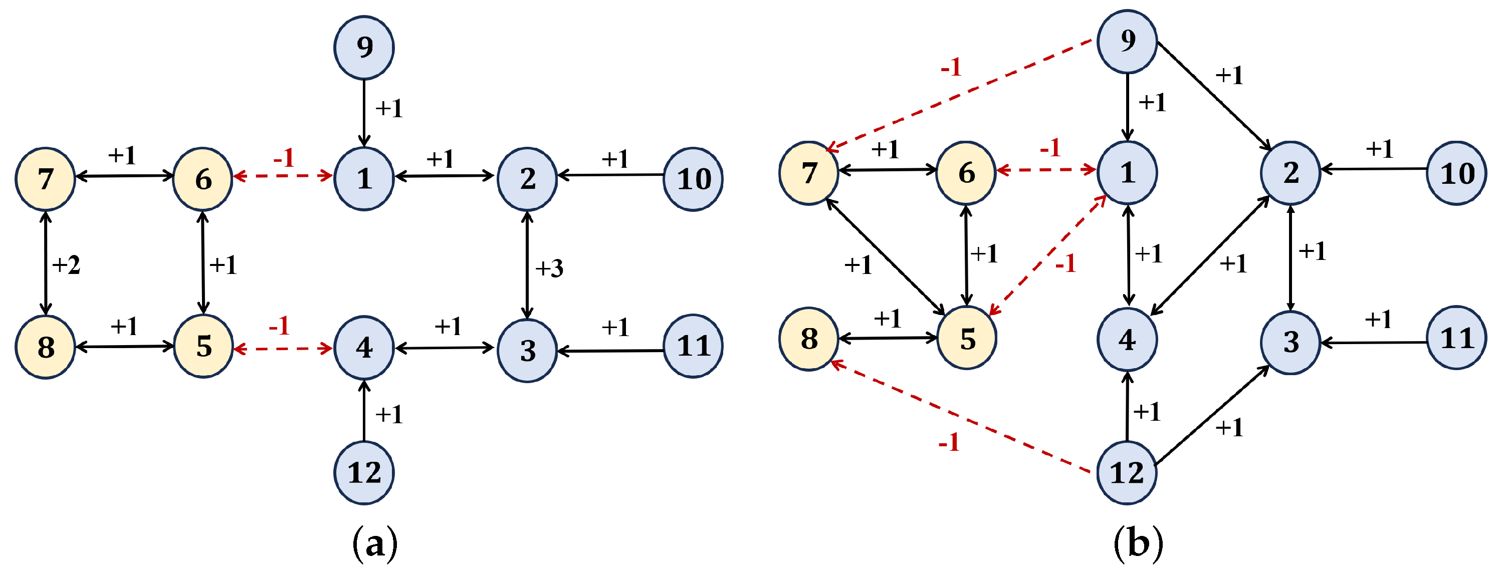
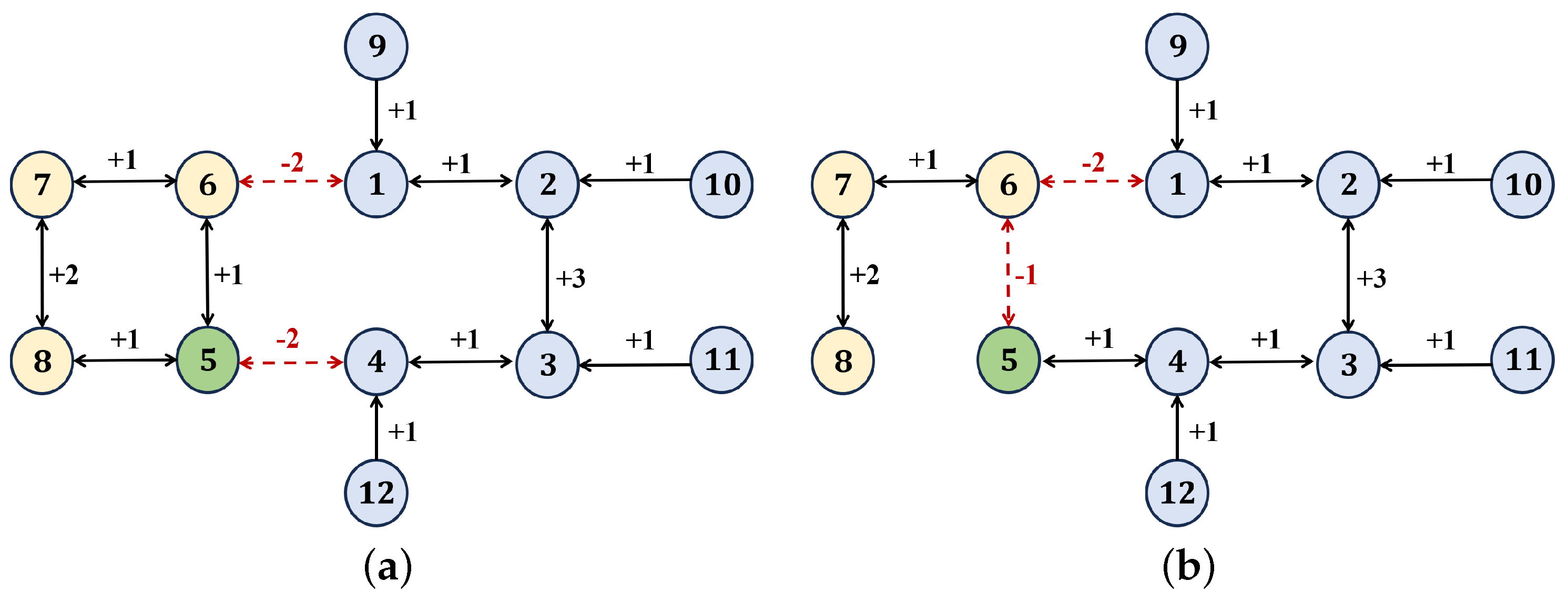
In this section, numerical simulations are conducted to verify the effectiveness of the proposed NN-based robust bipartite containment control scheme and to further demonstrate the feasibility of the fixed-time convergence framework under switching topologies. The simulation is implemented with a discrete time step of 0.01. There are 12 UAVs, including four leaders and eight followers. The follower UAVs are divided into two distinct factions: four followers exhibit cooperative interactions with the leaders, while the remaining four followers exhibit antagonistic interactions. The system is defined in a two-dimensional space (i.e., n = 2 , corresponding to the x- and y-channels). The initial positions and velocities of all UAVs are specified in Table 2 and Table 3. The communication topologies governing the networked UAV are depicted in Figure 2a,b. The topology switching signal σ ( t ) is defined as
σ ( t ) = 1 , t [ s T c , ( s + 1 ) T c ) , 2 , t [ ( s + 1 ) T c , ( s + 2 ) T c ) , s = 0 , 1 , 2 ,
where T c denotes the dwell time of each topology.
The uncertainty term in the follower model can be written as g i ( p i ( t ) , v i ( t ) ) = [ g i x ( p i ( t ) , v i ( t ) ) , g i y ( p i ( t ) , v i ( t ) ) ] T , where
g i x ( p i ( t ) , v i ( t ) ) = A x v i x ( t ) sin ( f x p i y ( t ) ) , g i y ( p i ( t ) , v i ( t ) ) = A y v i y ( t ) sin ( f y p i y ( t ) ) ,
and the specific parameter settings are shown in Table 4.
To enable the neural network estimator to approximate the uncertainties, each neural network is configured with 13 neurons. The centers of the Gaussian radial basis functions (6) are uniformly distributed over [ 4.5 t 3 5 t 2 , 4.5 t 3 + 5 t + 2 ] × [ 4.5 t 3 5 t 2 , 4.5 t 3 + 5 t + 2 ] , and the width is set as W k ( t ) = t + 5 t 1 / 2 + 1 . For the adaptive neural network weights θ ^ j in (21), we select σ = 29 and ρ = 0.5 . The initial weight matrix θ ^ is chosen as a zero matrix. Regarding the controller (32), the parameters are configured as follows α = β = 1.8 , κ 1 = κ 2 = 1 , κ 3 = κ 4 = 2 , κ 5 = 0.078 , κ 6 = 0.005 .

4.1. Fixed-Time Convergence Under Switching Topologies

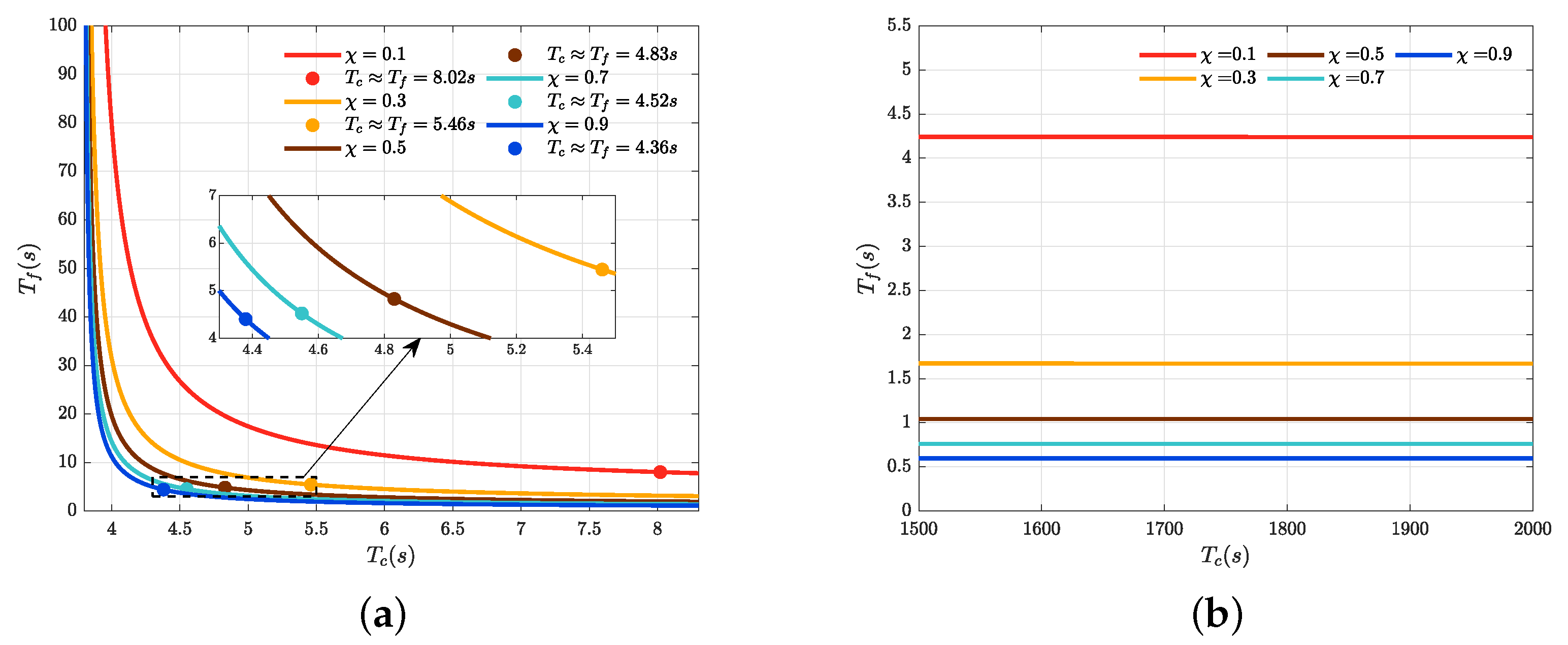
Based on the topology structure illustrated in Figure 2a,b, the parameters a = 0.5 and b = 1.5 are held constant. Through straightforward calculations, the topology-related parameters are obtained: Ξ 0 = 6.16 , Ξ 1 = 0.48 , Ξ 2 = 1.824 , Ξ 3 = 5.8 . Consequently, the minimum topology dwell time is determined as T min = 3.76   s . The relationship between the topology dwell time and the fixed time is depicted in Figure 3. As shown in Figure 3a,b, when the value of T c approaches the minimum topology dwell time (see Figure 3a), the fixed time T f significantly exceeds the dwell time T c , which clearly violates the system’s stability requirements. As the topology dwell time increases, the fixed time decreases rapidly until the condition T f = T c is reached. Beyond this point, the rate of decrease in fixed time gradually stabilizes. When the topology dwell time becomes sufficiently large (as illustrated in Figure 3a), the value of T c converges to a steady state. This result can be interpreted as the scenario where the topology remains unchanged (i.e., fixed topology), and it indirectly verifies that the fixed-time theory and control law proposed in this work remain valid for topology-invariant cases. Furthermore, it can be noted that as parameter x increases, the descent rate of T f accelerates. When T f = T c occurs, both T f and T c exhibit reduced values. However, according to (64), the parameter x must be constrained within the interval (0, 1). Additionally, as x increases, the residual set to which the system state converges widens. This indicates that increasing x does not consistently enhance system stability and may instead adversely affect the convergence precision.

4.2. Control Performance Evaluation

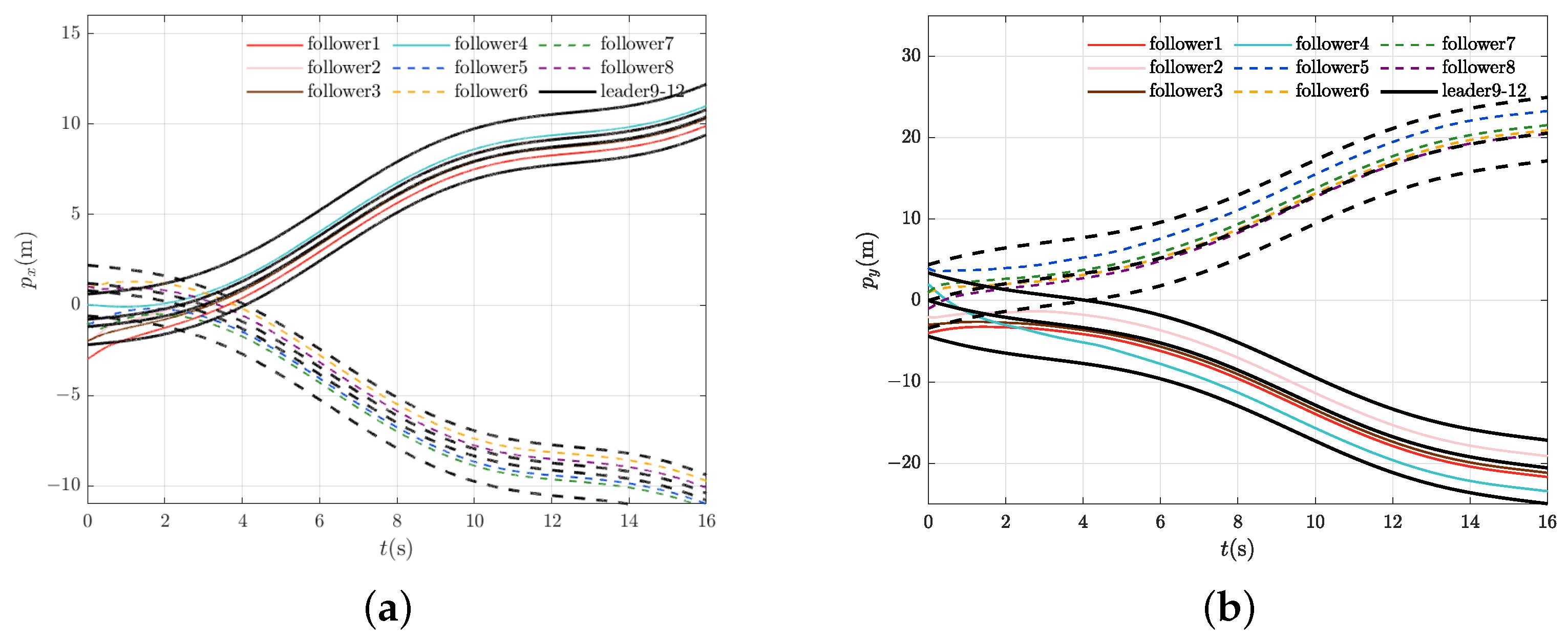
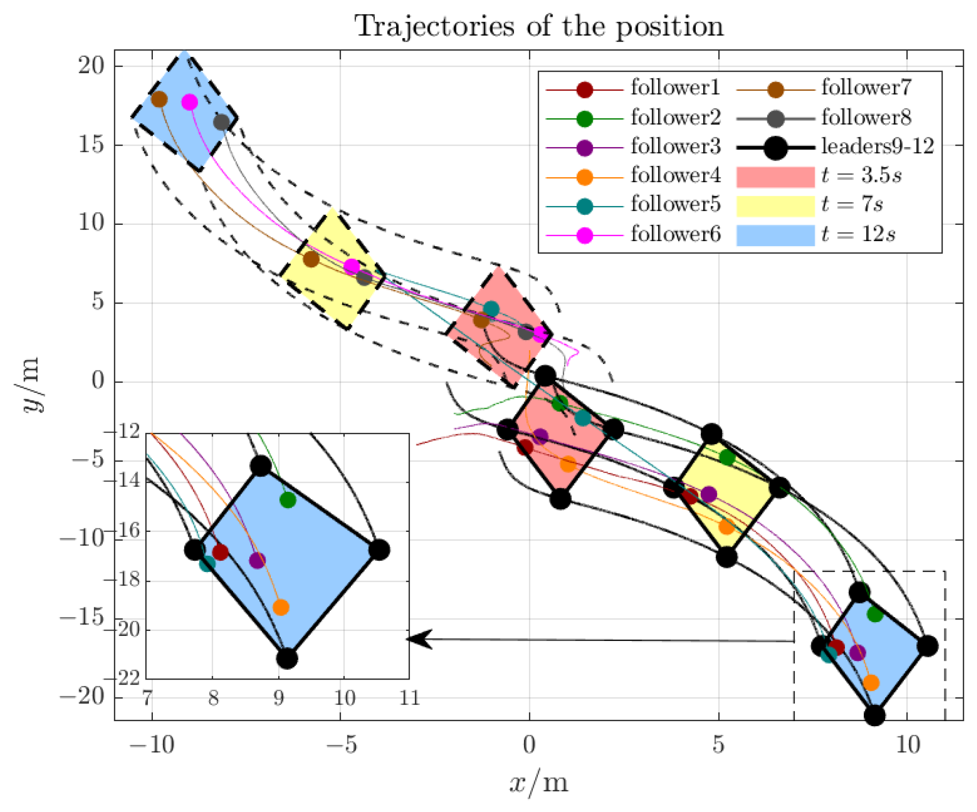
Based on the observations in Figure 3, a specific parameter configuration was selected with the topology dwell time fixed at T c = 6 s. The leader control input was set as u 0 i ( t ) = [ 0.3 sin ( t / 2 ) , 0.4 sin ( t / 2 ) ] T , and the convergence tuning parameter was chosen as χ = 0.5 . As illustrated in Figure 4, the four leaders dynamically formed a convex hull with a fixed geometric shape but a time-varying centroid. Simultaneously, the eight followers were divided into two antagonistic subgroups and achieved convergence to the leader-defined region within the prescribed fixed time. Importantly, despite the occurrence of topology switching events, all follower UAVs remained confined within the convex hull formed by the leaders (or their virtual extensions), thereby fulfilling the containment control objectives. These results further confirm the robustness of the proposed scheme under time-varying interaction structures and demonstrate its capability to maintain bipartite containment behavior under switching conditions.
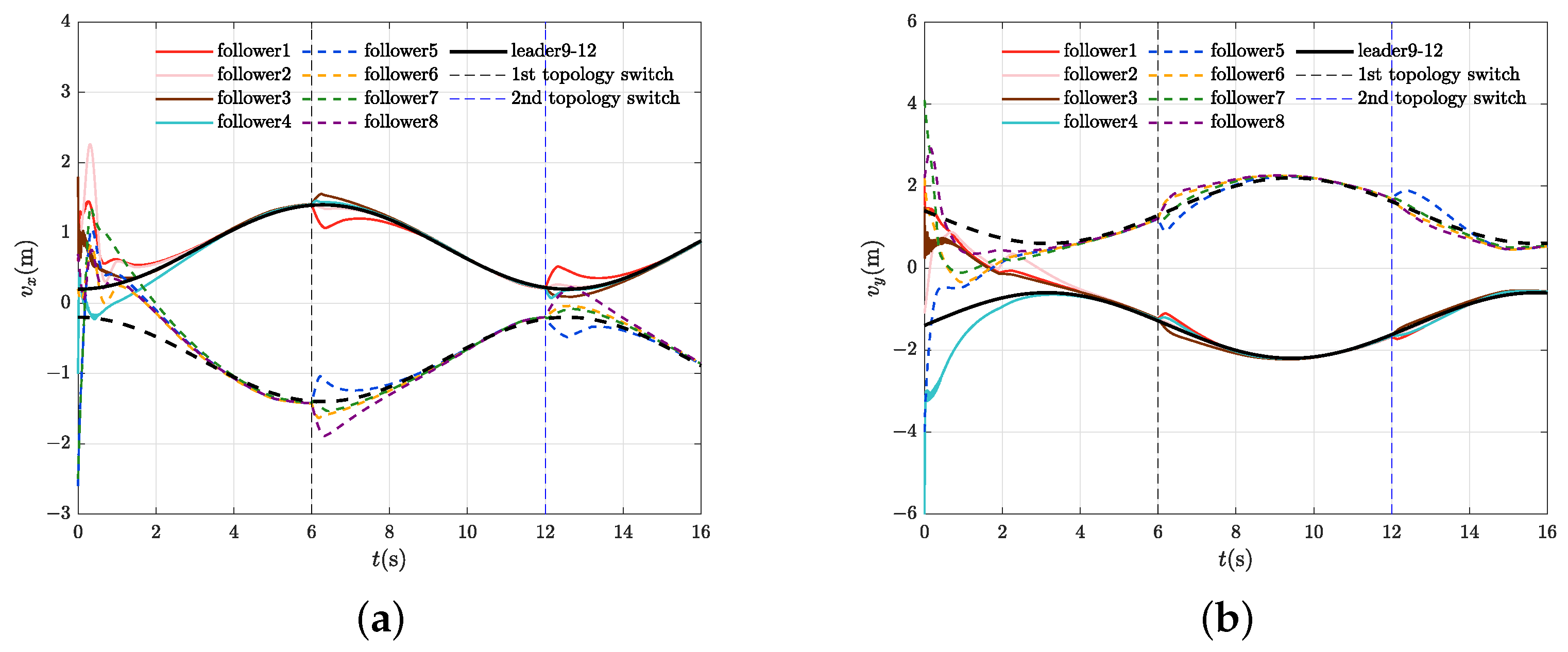
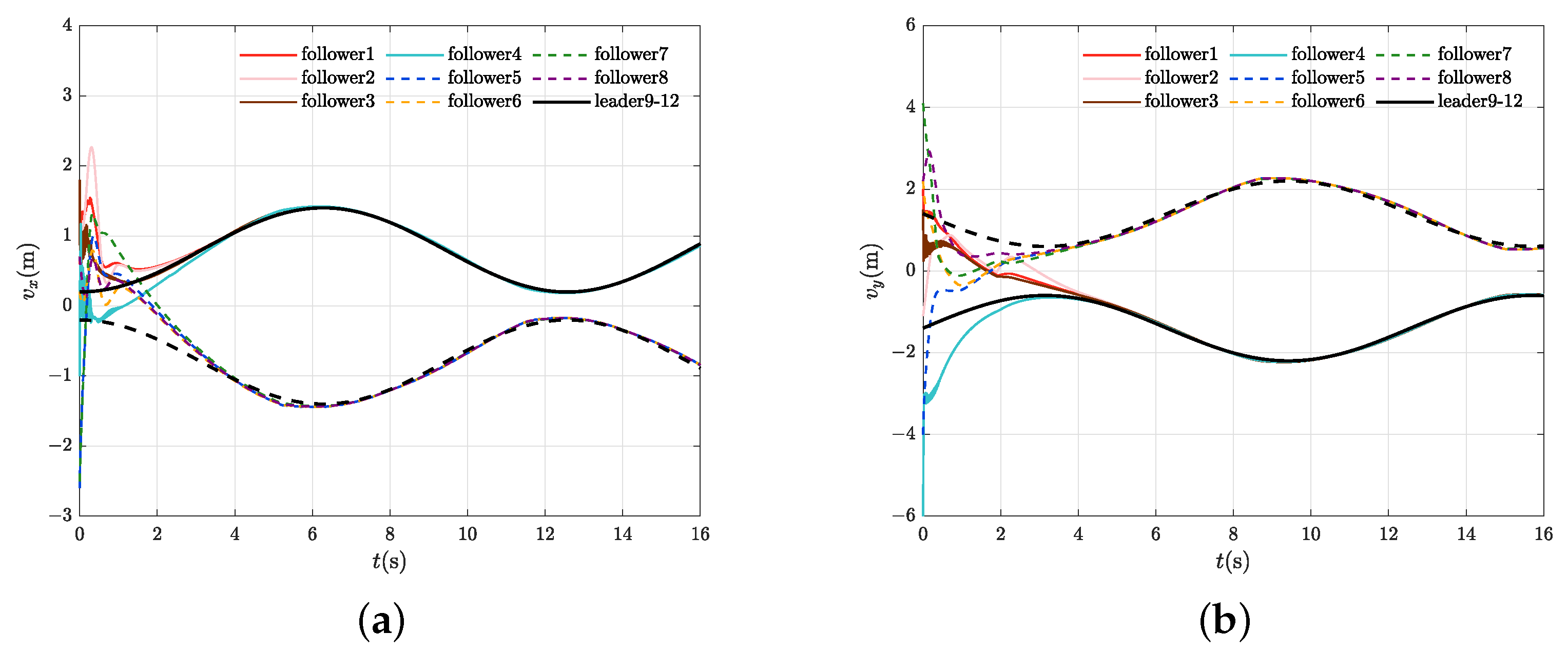
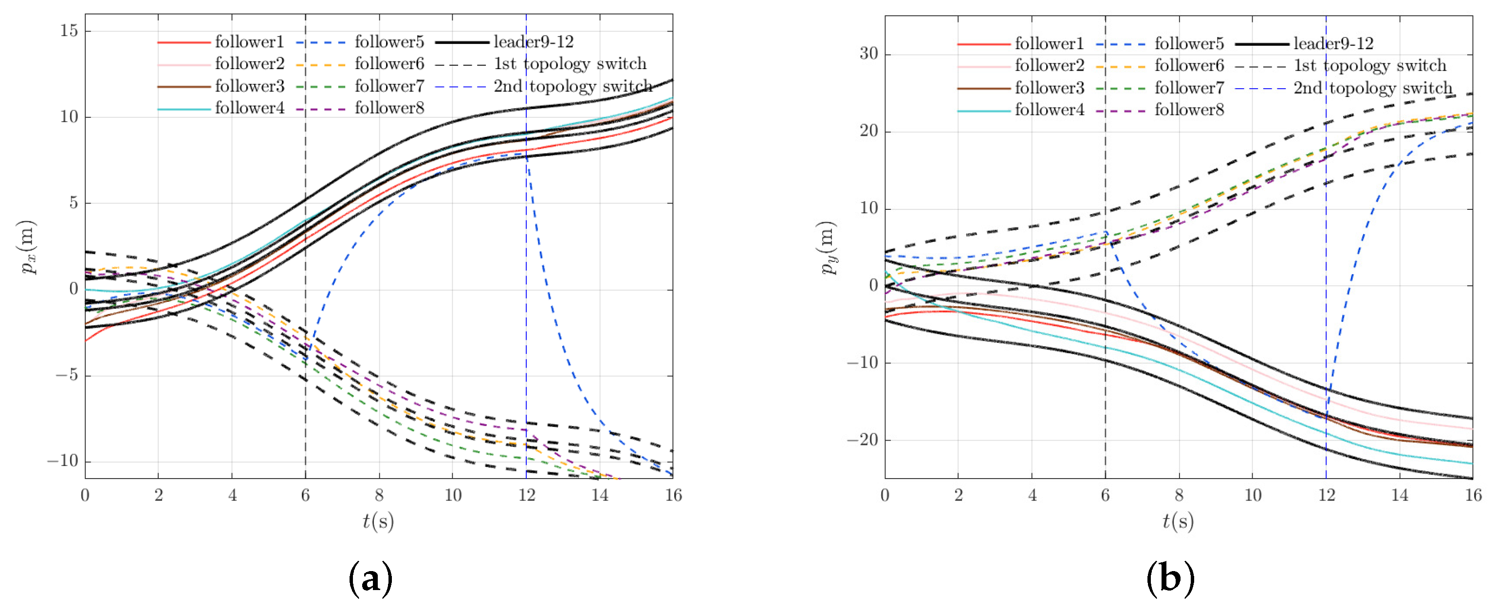
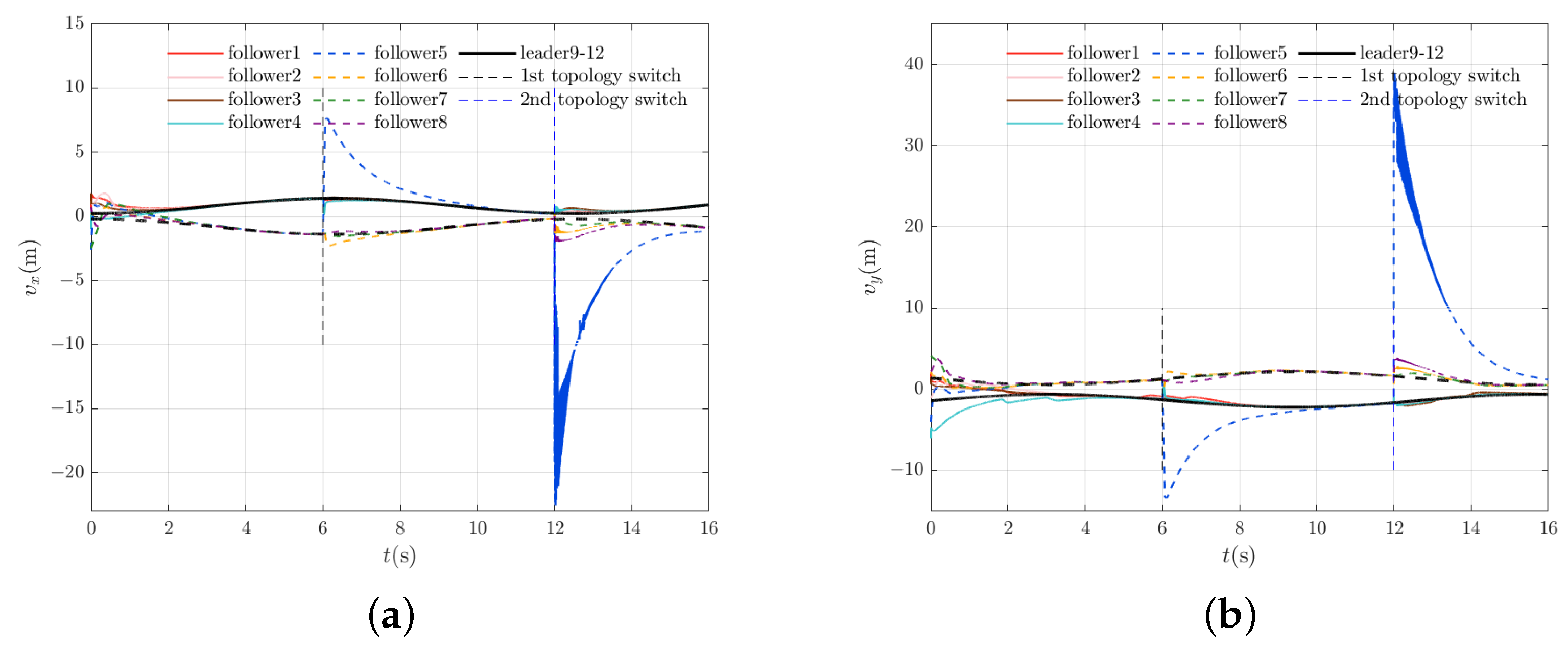
To further illustrate the performance of the proposed control strategy in a two-dimensional setting, Figure 5a,b show the position trajectories of all UAVs along the x- and y-channels, respectively, while Figure 6a,b depict the corresponding velocity responses. The simulation results indicate that all follower UAVs achieve velocity consensus with the leader group and enter the convex hull formed by the leaders within the prescribed fixed time. Although minor transient deviations are observed during topology switching, their magnitude remains bounded. As discussed in Remark 8, such effects can be further mitigated by employing smooth control approximations or reducing the extent of topology variation. Figure 7a,b demonstrate the approximation capability of the neural network estimator for uncertain terms in follower UAV models. The results reveal that the estimator achieves high approximation accuracy for uncertain terms, indicating that the designed neural network estimator can effectively achieve precise estimation of model uncertainties within the prescribed fixed time. This accurate estimation enables the generation of reliable feedforward reference signals, thereby facilitating closed-loop control implementation.
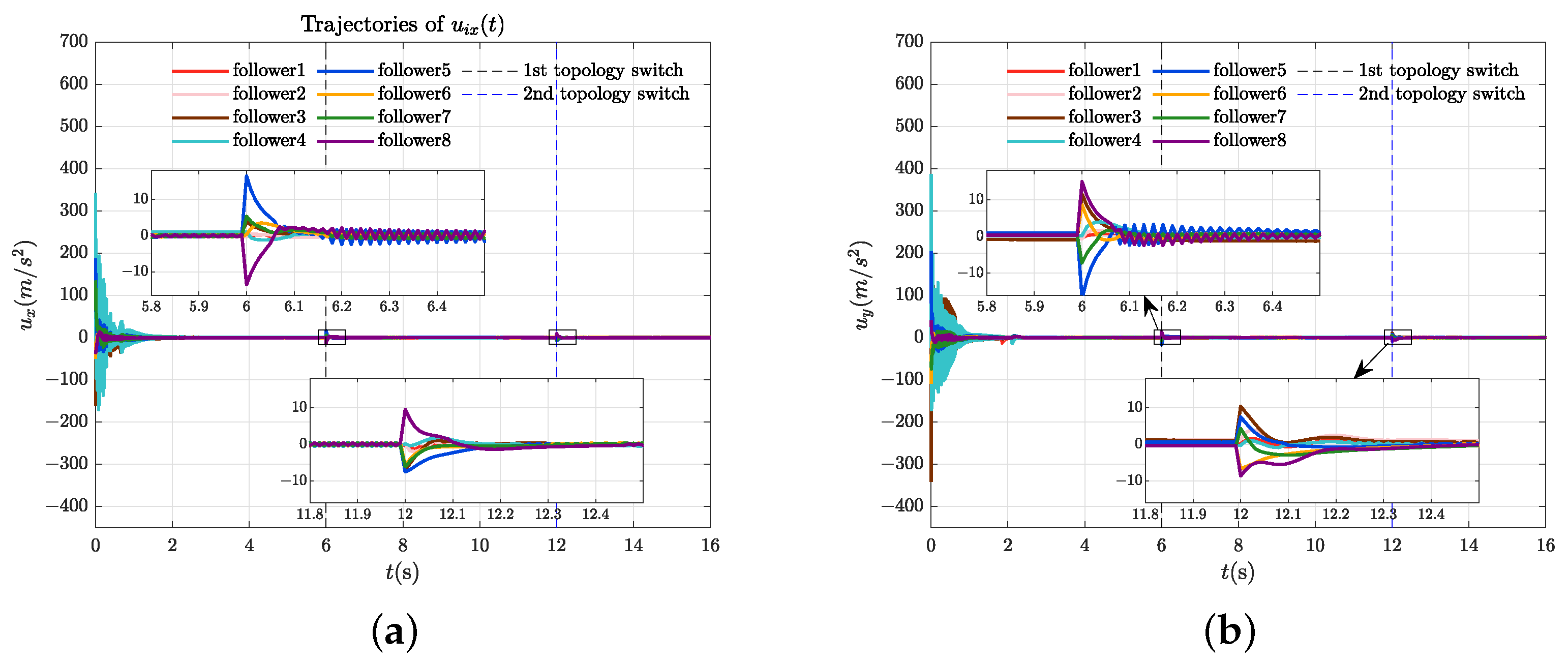
Additionally, Figure 8a,b depict the control input trajectories generated by the proposed robust control scheme for each UAV. During the initial transient phase, relatively large control inputs are applied to drive the system states toward the target set. As the system approaches stability, the input magnitudes gradually decrease and asymptotically converge to zero. Notably, during topology switching events, only slight input adjustments are required to preserve system stability. These results indicate that the proposed control strategy enables efficient stabilization with moderate initial effort and maintains robustness under dynamic network variations with minimal steady-state input. To highlight the advantages of our proposed fixed-time bipartite containment control strategy, Figure 9a,b present the bipartite containment position errors of the UAVs, while Figure 10a,b demonstrate their corresponding velocity errors.
Based on the findings in Figure 3, to demonstrate the versatility of the proposed scheme, we performed simulation verification under the fixed-topology communication scenario depicted in Figure 2a. As shown in Figure 11 and Figure 12, although our scheme was developed for switching topology conditions, the time to achieve control objectives and the tracking error under fixed topology conditions are essentially consistent with previous results. This further illustrates that fixed topology communication represents a special case of switching topology communication, and the proposed scheme can equally apply to static communication scenarios.
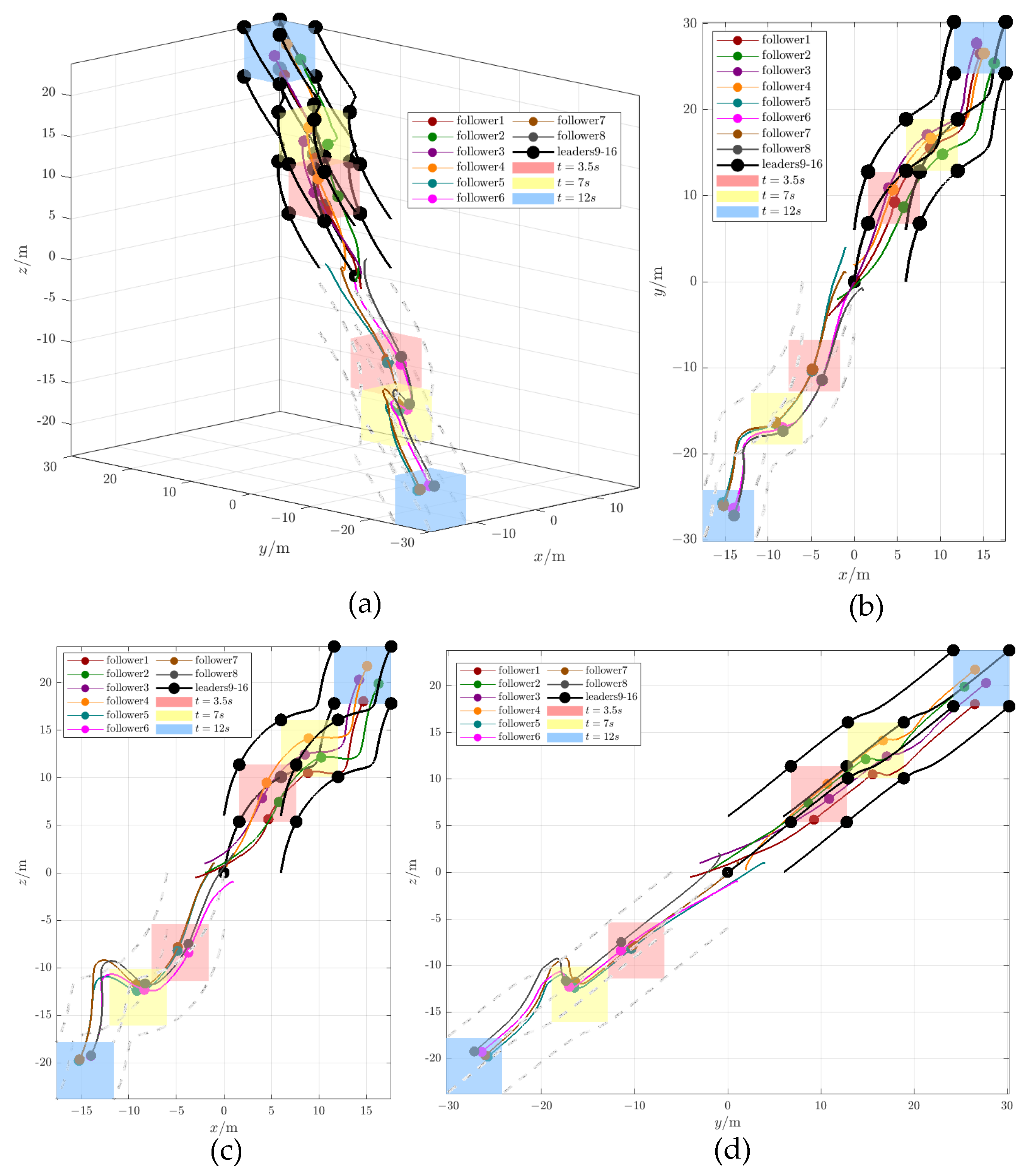
To further verify the scalability and three-dimensional applicability of the proposed controller, a simulation was performed with an increased number of UAVs and three-dimensional motion. The system comprises eight leaders and eight followers. The followers’ initial states are randomly initialized within [−5, 5] × [−5, 5] × [−5, 5]. The leaders’ initial positions form a [0, 6] × [0, 6] × [0, 6] cube, and their control input is u 0 i ( t ) = [ 0.3 sin ( t / 2 ) , 0.4 sin ( t / 2 ) ] T , 0.4 sin ( t / 2 ) ] T , all other items remain unchanged. The resulting three-dimensional trajectories are shown in Figure 13, which demonstrates that all followers converge to the moving convex hulls spanned by the leaders or virtual leaders in three-dimensional space, effectively validating the controller’s performance in a more realistic setting.

4.3. Control Performance Comparison and Quantification

This section aims to quantitatively evaluate the overall performance of the proposed controller through a comparison with a traditional fixed-time control method. To ensure a fair comparison, the identical simulation scenario from Section 4.1 (including switching topologies, nonlinear dynamics and initial conditions of networked UAVs, parameters, etc.) is used to compare the proposed controller against the traditional fixed-time containment controller presented in [31].
Figure 14 and Figure 15 show the position and velocity trajectories of the networked UAVs under the scheme proposed by [31], respectively. The scheme in [31] has slower convergence rates and larger transient deviations during topology switching events. Based on Lemma 6, this paper develops a topology-dependent multi-Lyapunov framework that not only achieves a fixed upper bound estimate for stability with reduced conservativeness but also enables a faster and smoother convergence process.
To quantitatively evaluate control accuracy and convergence performance, three widely used metrics are analyzed: Mean Absolute Error (MAE), Root Mean Square Error (RMSE), and convergence time t c . Their calculation formulas are as follows:
MAE = [ P MAE , V MAE ] = [ i = 1 N j = 1 n k T c ( k + 1 ) T c | p ˜ i j | d t N n T c , i = 1 N j = 1 n k T c ( k + 1 ) T c | v ˜ i j | d t N n T c ]
RMSE = [ P RMSE , V RMSE ] = [ i = 1 N j = 1 n k T c ( k + 1 ) T c p ˜ i j 2 d t N n T c , i = 1 N j = 1 n k T c ( k + 1 ) T c v ˜ i j 2 d t N n T c ]
t c = max { t | p ˜ 2 < 0.01 v ˜ 2 < 0.01 }
where k = 1 , 2 , , s .
The comparison results of performance used by different controllers are presented in Table 5. As demonstrated by the simulation results, the proposed scheme outperforms [31] in terms of tracking error and convergence rate.

4.4. Considerations for Special Circumstances

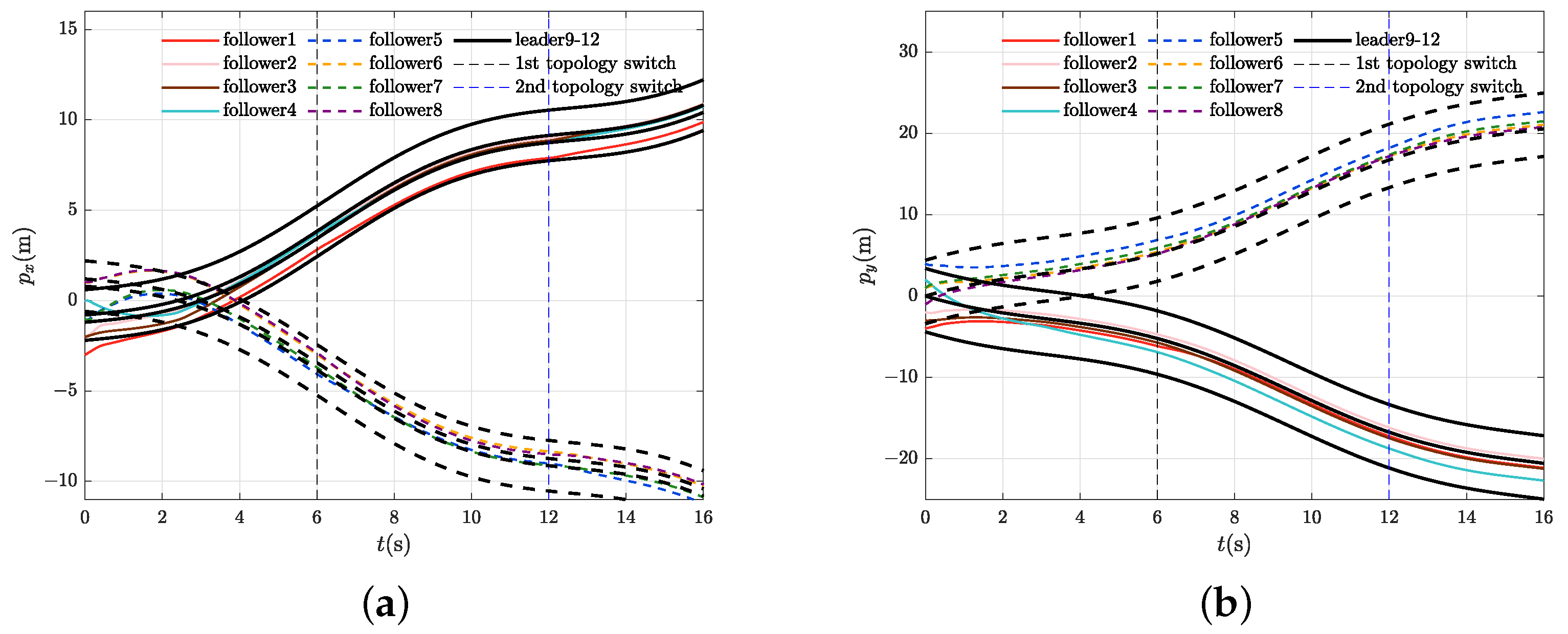
This section explores a special circumstance where this bipartition changes during operation Under conditions where Assumption 1 is not satisfied. We consider a scenario where Follower 5 switches its role from one faction C ( 2 ) f to the other faction C ( 1 ) f at t = 6 s. The new communication topology after the switch is depicted in Figure 16. All other control parameters and topology dwell times remain unchanged from the previous simulations. Figure 17 presents the resulting position trajectories. Figure 18 and Figure 19 plot the corresponding control inputs and velocity variations, respectively, which can the system can eventually achieve a new bipartite containment configuration for this specific topology. Follower 5 converges to the convex hull spanned by four leaders, consistent with its new cooperative role.
In more general cases, the outcome of a time-varying bipartition depends critically on the interplay of the new topology, the agent’s position in the network (e.g., being a root or leaf node), and the dwell time. Three outcomes are possible: (1) maintenance of the original containment, (2) convergence to a new containment (as shown here), or (3) system divergence. However, in practical scenarios, each UAV’s operation is often mission-specific. Once the system establishes a bipartition, communication links typically change only within the respective factions. Therefore, in this paper’s discussion of networked multi-UAV bipartite containment control scenarios, the Assumption 1 is not only reasonable but also a necessary condition for ensuring stable and feasible control.

5. Conclusions

This paper has addressed the fixed-time bipartite containment control problem for second-order networked UAVs under switching topologies. A fixed-time adaptive control scheme was developed based on the NN approximation to compensate for unknown nonlinearities in the follower dynamics. By constructing topology-dependent multiple Lyapunov functions and imposing appropriate dwell-time conditions, sufficient criteria were established to ensure fixed-time convergence of all followers to the convex hull spanned by the leaders. The proposed method accounts for cooperative and antagonistic interactions within switching topologies and ensures robustness against switching-induced perturbations. Numerical simulations were provided to support the theoretical findings, demonstrating that the proposed control protocol achieves fixed-time containment under dynamically changing network topologies. Future work will explore several promising directions. First, the proposed fixed-time framework will be extended to achieve prescribed-time convergence under switching topologies. Second, we will investigate deriving explicit a priori bounds on the magnitude of transient oscillations induced by topology switching. Furthermore, the extension of the proposed framework to important practical aspects with communication bandwidth limitations, and the development of efficient quantization strategies for resource-constrained UAV platforms.

Author Contributions

Y.K.: Conceptualization, Methodology, Writing—original draft. M.S.: Writing—original draft, Numerical simulation. K.Q.: Validation, Writing—review & editing. Y.Y. and R.Z.: Writing—review & editing. All authors have read and agreed to the published version of the manuscript.

Funding

This work was supported by the Natural Science Foundation of Sichuan Province (2024NSFSC0021), the Sichuan Science and Technology Programs (MZGC20240139), and the Fundamental Research Funds for the Central Universities (ZYGX2024K028, ZYGX2025K028).

Data Availability Statement

The original contributions presented in this study are included in the article. Further inquiries can be directed to the corresponding author.

Conflicts of Interest

Authors Rui Zhou and Yuan Yao were employed by the company Sichuan Tengdun Science and Technology Innovation. The remaining authors declare that the research was conducted in the absence of any commercial or financial relationships that could be construed as a potential conflict of interest.

References

  1. Yang, C.; Liu, Y.; Gao, H. Reliability-Constrained Uncertain Spacecraft Sliding Mode Attitude Tracking Control with Interval Parameters. IEEE Trans. Aerosp. Electron. Syst. 2025, 61, 6589–6600. [Google Scholar] [CrossRef]
  2. Li, W.; Zhou, S.; Shi, M.; Yue, J.; Lin, B.; Qin, K. Collision Avoidance Time-Varying Group Formation Tracking Control for Multi-Agent Systems. Appl. Intell. 2025, 55, 175. [Google Scholar] [CrossRef]
  3. Yang, S.; Pan, Y.; Cao, L.; Chen, L. Predefined-Time Fault-Tolerant Consensus Tracking Control for Multi-UAV Systems With Prescribed Performance and Attitude Constraints. IEEE Trans. Aerosp. Electron. Syst. 2024, 60, 4058–4072. [Google Scholar] [CrossRef]
  4. Ren, M.; Liu, W.; Song, K.; Shi, L.; Xiong, Z. Containment Control of Multirobot Systems With Nonuniform Time-Varying Delays. IEEE Trans. Robot. 2025, 41, 1657–1672. [Google Scholar] [CrossRef]
  5. Xiao, F.; Liu, Y.; Zhang, X.; Wei, B. Fully Distributed Event-Triggered Security Control for DC Microgrids Subject to DoS Attacks. IEEE Trans. Smart Grid 2025, 16, 929–941. [Google Scholar] [CrossRef]
  6. Li, W.; Yan, S.; Shi, L.; Yue, J.; Shi, M.; Lin, B.; Qin, K. Multiagent Consensus Tracking Control over Asynchronous Cooperation–Competition Networks. IEEE Trans. Cybern. 2025, 55, 4347–4360. [Google Scholar] [CrossRef]
  7. Shi, L.; Yan, S.; Li, W. Consensus and Products of Substochastic Matrices: Convergence Rate with Communication Delays. IEEE Trans. Syst. Man. Cybern. Syst. 2025, 55, 4752–4761. [Google Scholar] [CrossRef]
  8. Li, W.; Shi, L.; Shi, M.; Lin, B.; Qin, K. Cooperative Formation Tracking of Multi-Agent Systems over Switching Signed Networks. IEEE Trans. Control Netw. Syst. 2025, 1–11. [Google Scholar] [CrossRef]
  9. Ma, Y.S.; Che, W.W.; Deng, C.; Wu, Z.G. Observer-Based Event-Triggered Containment Control for MASs Under DoS Attacks. IEEE Trans. Cybern. 2022, 52, 13156–13167. [Google Scholar] [CrossRef]
  10. Li, W.; Shi, L.; Shi, M.; Yue, J.; Lin, B.; Qin, K. Leader-Following Containment Control of Hybrid Fractional-Order Networked Agents with Nonuniform Time Delays. IEEE Trans. Signal Inf. Process. Netw. 2023, 9, 750–760. [Google Scholar] [CrossRef]
  11. Lin, G.; Li, H.; Ma, H.; Zhou, Q. Distributed Containment Control for Human-in-the-Loop MASs With Unknown Time-Varying Parameters. IEEE Trans. Circuits Syst. I Regul. Pap. 2022, 69, 5300–5311. [Google Scholar] [CrossRef]
  12. Li, P.; Jabbari, F.; Sun, X.M. Containment control of multi-agent systems with input saturation and unknown leader inputs. Automatica 2021, 130, 109677. [Google Scholar] [CrossRef]
  13. Ye, Y.; Chen, H.; Tao, J.; Cai, Q.; Shi, P. Containment control for fractional-order networked system with intermittent sampled position communication. Neural Netw. 2024, 178, 106425. [Google Scholar] [CrossRef] [PubMed]
  14. Li, W.; Shi, L.; Shi, M.; Yue, J.; Lin, B.; Qin, K. Analyzing Containment Control Performance for Fractional-Order Multi-Agent Systems via a Delay Margin Perspective. IEEE Trans. Netw. Sci. Eng. 2024, 11, 2810–2821. [Google Scholar] [CrossRef]
  15. Ji, M.; Ferrari-Trecate, G.; Egerstedt, M.; Buffa, A. Containment Control in Mobile Networks. IEEE Trans. Autom. Control 2008, 53, 1972–1975. [Google Scholar] [CrossRef]
  16. Wang, F.; Yang, H.; Zhang, S.; Han, F.-J. Containment control for first-order multi-agent systems with time-varying delays and uncertain topologies. Commun. Theor. Phys. 2016, 66, 249. [Google Scholar] [CrossRef]
  17. Cao, Y.; Stuart, D.; Ren, W.; Meng, Z. Distributed Containment Control for Multiple Autonomous Vehicles With Double-Integrator Dynamics: Algorithms and Experiments. IEEE Trans. Control Syst. Technol. 2011, 19, 929–938. [Google Scholar] [CrossRef]
  18. Wang, Y.; Zhang, J.X.; Zhang, X. Fuzzy control of singular fractional order multi-agent systems with actuator saturation. Inf. Sci. 2024, 665, 120397. [Google Scholar] [CrossRef]
  19. Li, Y.; Hua, C.; Wu, S.; Guan, X. Output Feedback Distributed Containment Control for High-Order Nonlinear Multiagent Systems. IEEE Trans. Cybern. 2017, 47, 2032–2043. [Google Scholar] [CrossRef] [PubMed]
  20. Yao, D.; Wu, Y.; Ren, H.; Li, H.; Shi, Y. Event-based adaptive sliding-mode containment control for multiple networked mechanical systems with parameter uncertainties. IEEE Trans. Autom. Sci. Eng. 2025, 22, 264–275. [Google Scholar] [CrossRef]
  21. Lu, P.; Jiang, Q.; Tian, Y.; Liu, H.; Du, C. Fully distributed finite-time adaptive robust time-varying formation-containment control for satellite formation. Int. J. Control 2023, 97, 1223–1239. [Google Scholar] [CrossRef]
  22. Mei, J.; Ren, W.; Li, B.; Ma, G. Distributed Containment Control for Multiple Unknown Second-Order Nonlinear Systems With Application to Networked Lagrangian Systems. IEEE Trans. Neural Netw. Learn. Syst. 2015, 26, 1885–1899. [Google Scholar] [CrossRef]
  23. Wang, C.; Wen, C.; Hu, Q.; Wang, W.; Zhang, X. Distributed Adaptive Containment Control for a Class of Nonlinear Multiagent Systems With Input Quantization. IEEE Trans. Neural Netw. Learn. Syst. 2018, 29, 2419–2428. [Google Scholar] [CrossRef]
  24. Wang, X.; Xu, R.; Huang, T.; Kurths, J. Event-Triggered Adaptive Containment Control for Heterogeneous Stochastic Nonlinear Multiagent Systems. IEEE Trans. Neural Netw. Learn. Syst. 2024, 35, 8524–8534. [Google Scholar] [CrossRef]
  25. Wang, L.; Yan, H.; Hu, X.; Li, Z.; Wang, M. Fixed-Time Bipartite Containment Control for Heterogeneous Multiagent Systems Under DoS Attacks: An Event-Triggered Mechanism. IEEE Trans. Syst. Man. Cybern. Syst. 2025, 55, 2782–2794. [Google Scholar] [CrossRef]
  26. Meng, Z.; Ren, W.; You, Z. Distributed finite-time attitude containment control for multiple rigid bodies. Automatica 2010, 46, 2092–2099. [Google Scholar] [CrossRef]
  27. He, X.; Wang, Q.; Yu, W. Finite-Time Containment Control for Second-Order Multiagent Systems Under Directed Topology. IEEE Trans. Circuits Syst. II Express Briefs 2014, 61, 619–623. [Google Scholar] [CrossRef]
  28. Wang, H.; Wang, C.; Xie, G. Finite-time containment control of multi-agent systems with static or dynamic leaders. Neurocomputing 2017, 226, 1–6. [Google Scholar] [CrossRef]
  29. Shahamatkhah, E.; Tabatabaei, M. Containment control of linear discrete-time fractional-order multi-agent systems with time-delays. Neurocomputing 2020, 385, 42–47. [Google Scholar] [CrossRef]
  30. Wang, L.; Liu, X.; Cao, J.; Hu, X. Fixed-Time Containment Control for Nonlinear Multi-Agent Systems with External Disturbances. IEEE Trans. Circuits Syst. II Express Briefs 2022, 69, 459–463. [Google Scholar] [CrossRef]
  31. Chen, C.; Han, Y.; Zhu, S.; Zeng, Z. Neural Network-Based Fixed-Time Tracking and Containment Control of Second-Order Heterogeneous Nonlinear Multiagent Systems. IEEE Trans. Neural Netw. Learn. Syst. 2024, 35, 11565–11579. [Google Scholar] [CrossRef]
  32. Altafini, C. Dynamics of Opinion Forming in Structurally Balanced Social Networks. PLoS ONE 2012, 7, e38135. [Google Scholar] [CrossRef]
  33. Uchibe, E.; Asada, M. Incremental Coevolution with Competitive and Cooperative Tasks in a Multirobot Environment. Proc. IEEE 2006, 94, 1412–1424. [Google Scholar] [CrossRef]
  34. Lu, R.; Wu, J.; Zhan, X.; Yan, H. Finite-Time Bipartite Consensus for Second-Order Nonlinear Multi-Agent Systems Under Random Switching Topologies. IEEE Trans. Circuits Syst. II Express Briefs 2023, 70, 4474–4478. [Google Scholar] [CrossRef]
  35. Zhang, H.; Duan, J.; Wang, Y.; Gao, Z. Bipartite Fixed-Time Output Consensus of Heterogeneous Linear Multiagent Systems. IEEE Trans. Cybern. 2021, 51, 548–557. [Google Scholar] [CrossRef] [PubMed]
  36. Li, W.; Ren, R.; Shi, M.; Lin, B.; Qin, K. Seeking Secure Adaptive Distributed Discrete-Time Observer for Networked Agent Systems under External Cyber Attacks. IEEE Trans. Consum. Electron. 2025, 71, 918–930. [Google Scholar] [CrossRef]
  37. Li, W.; Qin, K.; Li, G.; Shi, M.; Zhang, X. Robust Bipartite Tracking Consensus of Multi-Agent Systems via Neural Network Combined with Extended High-Gain Observer. ISA Trans. 2023, 136, 31–45. [Google Scholar] [CrossRef] [PubMed]
  38. Liang, Z.; Tang, Z.; Ding, D.; Feng, J. Bipartite formation control of second-order multi-agent systems with antagonistic interactions under dynamic event-triggered adaptive schemes. Inf. Sci. 2025, 690, 121606. [Google Scholar] [CrossRef]
  39. Li, W.; Yue, J.; Shi, M.; Lin, B.; Qin, K. Neural network-based dynamic target enclosing control for uncertain nonlinear multi-agent systems over signed networks. Neural Netw. 2025, 184, 107057. [Google Scholar] [CrossRef]
  40. Fan, S.; Peng, F.; Liu, X.; Wang, T.; Qiu, J. Bipartite Containment Control of Multi-Agent Systems Subject to Adversarial Inputs Based on Zero-Sum Game. Inf. Sci. 2024, 681, 121234. [Google Scholar] [CrossRef]
  41. Liu, Z.; Zhang, H.; Wang, Z. Bipartite containment control of multi-agent systems under DoS attacks: An event-triggered scheme. Int. J. Robust Nonlinear Control. 2025, 35, 479–495. [Google Scholar] [CrossRef]
  42. Meng, D. Bipartite containment tracking of signed networks. Automatica 2017, 79, 282–289. [Google Scholar] [CrossRef]
  43. Zhu, Z.H.; Hu, B.; Guan, Z.H.; Zhang, D.X.; Li, T. Observer-Based Bipartite Containment Control for Singular Multi-Agent Systems Over Signed Digraphs. IEEE Trans. Circuits Syst. I Regul. Pap. 2021, 68, 444–457. [Google Scholar] [CrossRef]
  44. Guang, W.; Wang, X.; Zhang, W.; Li, H.; Li, H.; Huang, T. Fixed-Time Optimal Bipartite Containment Control for Stochastic Nonlinear Multiagent Systems With Unknown Hysteresis. IEEE Trans. Autom. Sci. Eng. 2025, 22, 5516–5525. [Google Scholar] [CrossRef]
  45. Wu, X.; Ding, S.; Xu, N.; Niu, B.; Zhao, X. Periodic event-triggered bipartite containment control for nonlinear multi-agent systems with input delay. Int. J. Syst. Sci. 2024, 55, 2008–2022. [Google Scholar] [CrossRef]
  46. Liu, Y.; Zhang, H.; Shi, Z.; Gao, Z. Neural-Network-Based Finite-Time Bipartite Containment Control for Fractional-Order Multi-Agent Systems. IEEE Trans. Neural Netw. Learn. Syst. 2023, 34, 7418–7429. [Google Scholar] [CrossRef]
  47. Liu, Z.; Zhan, X.; Han, T.; Yan, H. Distributed adaptive finite-time bipartite containment control of linear multi-agent systems. IEEE Trans. Circuits Syst. II Express Briefs 2022, 69, 4354–4358. [Google Scholar] [CrossRef]
  48. Yu, X.; Wang, G.; Jia, L.; Zhang, H. Event-Triggered Practical Fixed-Time Containment Control for Stochastic Multiagent Systems With Input Delay. IEEE Trans. Fuzzy Syst. 2024, 32, 2762–2774. [Google Scholar] [CrossRef]
  49. Zhang, L.; Liu, S.; Hua, C. Dynamic Event/Self-Triggered Full-State Bipartite Containment Control for Nonlinear Multi-Agent Systems Under Switching Topologies. IEEE Trans. Circuits Syst. I Regul. Pap. 2024, 71, 1852–1862. [Google Scholar] [CrossRef]
  50. Yang, R.; Liu, S.; Li, X.; Xiao, J. Bipartite containment control of fractional multi-agent systems with input delay on switching signed directed networks. ISA Trans. 2023, 135, 130–137. [Google Scholar] [CrossRef]
  51. Guo, J.; Qi, J.; Wang, M.; Wu, C.; Yang, G. Collision-Free Distributed Control for Multiple Quadrotors in Cluttered Environments With Static and Dynamic Obstacles. IEEE Robot. Autom. Lett. 2023, 8, 1501–1508. [Google Scholar] [CrossRef]
  52. Zhou, H.; Tong, S. Fuzzy Adaptive Resilient Formation Control for Nonlinear Multiagent Systems Subject to DoS Attacks. IEEE Trans. Fuzzy Syst. 2024, 32, 1446–1454. [Google Scholar] [CrossRef]
  53. Trentelman, H.; Stoorvogel, A.; Hautus, M.; Dewell, L. Control Theory for Linear Systems. Appl. Mech. Rev. 2002, 55, B87. [Google Scholar] [CrossRef]
  54. Hardy, G.; Littlewood, J.; Polya, G. Inequalities; Cambridge University Press: Cambridge, UK, 1952. [Google Scholar]
  55. Zou, A.; de Ruiter, A.; Kumar, K. Distributed finite-time velocity-free attitude coordination control for spacecraft formations. Automatica 2016, 67, 46–53. [Google Scholar] [CrossRef]
  56. Dong, Y.; Lu, W.; Chen, J.; Cao, J.; Xu, S. Adaptive neural network-based practical fixed-time consensus tracking for second-order nonlinear multi-agent systems with switching topologies. Int. J. Robust Nonlinear Control 2024, 34, 8442–8464. [Google Scholar] [CrossRef]
  57. Cui, Q.; Song, Y.; Wen, C. Prescribed Time Consensus Control of Multiagent Systems With Minimized Time-Varying Cost Function. IEEE Trans. Autom. Control 2024, 69, 3381–3388. [Google Scholar] [CrossRef]
  58. Aghababa, M.P.; Aghababa, H. A general nonlinear adaptive control scheme for finite-time synchronization of chaotic systems with uncertain parameters and nonlinear inputs. Nonlinear Dyn. 2012, 69, 1903–1914. [Google Scholar] [CrossRef]
  59. Boyd, S.; El Ghaoui, L.; Feron, E.; Balakrishnan, V. Linear Matrix Inequalities in System and Control Theory; SIAM: Philadelphia, PA, USA, 1994. [Google Scholar]
  60. Dang, R.; Tang, W.; Sheng, Y.; Xiao, Q.; Zeng, Z.; Huang, T. Dynamic Event-Triggered Bipartite Consensus for Multiagent Systems Under Switching Topologies on Time Scales. IEEE Trans. Syst. Man. Cybern. Syst. 2025, 55, 6359–6368. [Google Scholar] [CrossRef]
  61. Shi, Y.; Li, J.; Lv, M.; Wang, N.; Zhang, B. Distributed Consensus Control for 6-DOF Fixed-Wing Multi-UAVs in Asynchronously Switching Topologies. IEEE Trans. Veh. Technol. 2025, 74, 5649–5663. [Google Scholar] [CrossRef]
  62. Ba, D.; Li, Y.X.; Tong, S. Fixed-time adaptive neural tracking control for a class of uncertain nonstrict nonlinear systems. Neurocomputing 2019, 363, 273–280. [Google Scholar] [CrossRef]
  63. Li, M.; Zhang, K.; Liu, Y.; Song, F.; Li, T. Prescribed-Time Consensus of Nonlinear Multi-Agent Systems by Dynamic Event-Triggered and Self-Triggered Protocol. IEEE Trans. Autom. Sci. Eng. 2025, 22, 16768–16779. [Google Scholar] [CrossRef]
  64. Zheng, X.; Ma, H.; Zhou, Q.; Li, H. Neural-based prescribed-time consensus control for multiagent systems via dynamic memory event-triggered mechanism. Sci. China Technol. Sci. 2025, 68, 1–11. [Google Scholar] [CrossRef]
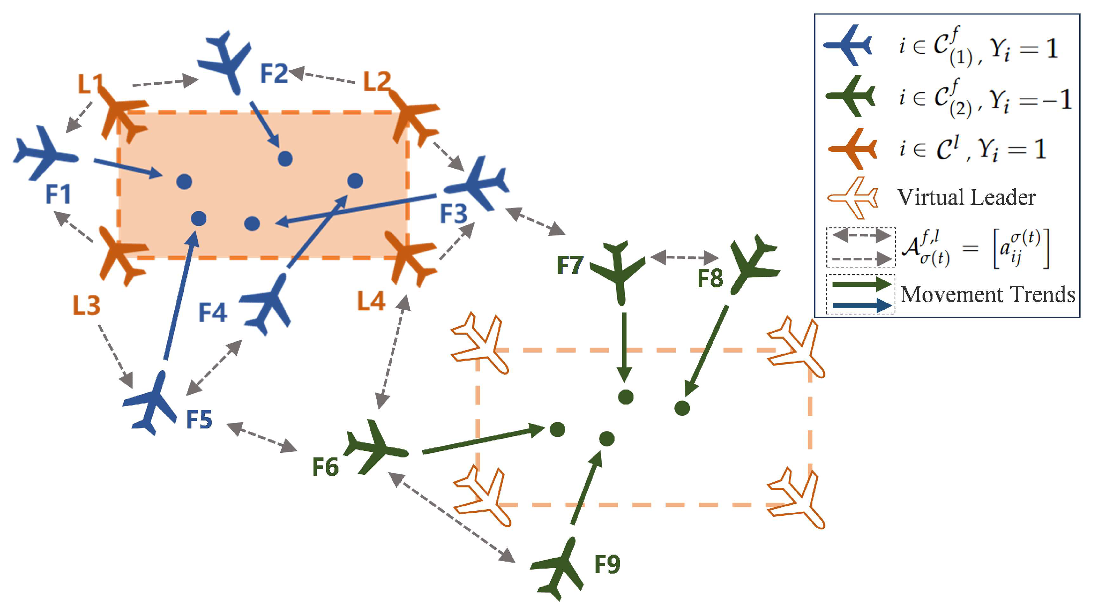
Figure 1. Illustration of UAV interactions and the control objective under a signed graph. The orange area and blank area enclosed by the orange line area represent the actual convex hull and virtual convex hull of networked, respectively.
Drones 09 00725 g001
Figure 2. The communication topologies among UAVs. (a) σ ( t ) = 1 , (b) σ ( t ) = 2 .
Drones 09 00725 g002
Figure 3. Relationship between T c and T f for different values of χ ; (a) 3.76   s < T c < 8.5   s , (b) 1500   s < T c < 2000   s .
Drones 09 00725 g003
Figure 4. The position trajectories of networked UAVs.
Drones 09 00725 g004
Figure 5. The trajectories of p i ( t ) and p 0 i ( t ) ; (a) the curve of p i x ( t ) and p 0 i x ( t ) ; (b) the curve of p i y ( t ) and p 0 i y ( t ) .
Drones 09 00725 g005
Figure 6. The trajectories of v i ( t ) and v 0 i ( t ) ; (a) the curve of v i x ( t ) and v 0 i x ( t ) ; (b) the curve of v i y ( t ) and v 0 i y ( t ) .
Drones 09 00725 g006
Figure 7. The unknown nonlinear function approximation; (a) the curve of g ˜ i x ( t ) , (b) the curve of g ˜ i y ( t ) .
Drones 09 00725 g007
Figure 8. The control input of follower UAVs; (a) the curve of u i x ( t ) , (b) the curve of u i y ( t ) .
Drones 09 00725 g008
Figure 9. The position error of bipartite containment control; (a) the curve of p ˜ i x ( t ) , (b) the curve of p ˜ i y ( t ) .
Drones 09 00725 g009
Figure 10. The velocity error of bipartite containment control; (a) the curve of v ˜ i x ( t ) , (b) the curve of v ˜ i y ( t ) .
Drones 09 00725 g010
Figure 11. The trajectories of p i ( t ) and p 0 i ( t ) over topology G σ ( t ) f , l in Figure 2a; (a) the curve of p i x ( t ) and p 0 i x ( t ) , (b) the curve of p i y ( t ) and p 0 i y ( t ) .
Drones 09 00725 g011
Figure 12. The trajectories of v i ( t ) and v 0 i ( t ) over topology G σ ( t ) f , l in Figure 2a; (a) the curve of v i x ( t ) and v 0 i x ( t ) , (b) the curve of v i y ( t ) and v 0 i y ( t ) .
Drones 09 00725 g012
Figure 13. The position trajectories of the networked UAVs in three-dimensional space; (a) three-dimensional image, (b) xy-plane image, (c) xz-plane image, (d) yz-plane image.
Drones 09 00725 g013
Figure 14. The trajectories of p i ( t ) and p 0 i ( t ) under traditional fixed-time controller in [31]; (a) the curve of p i x ( t ) and p 0 i x ( t ) , (b) the curve of p i y ( t ) and p 0 i y ( t ) .
Drones 09 00725 g014
Figure 15. The trajectories of v i ( t ) and v 0 i ( t ) under traditional fixed-time controller [31]; (a) the curve of v i x ( t ) and v 0 i x ( t ) , (b) the curve of v i y ( t ) and v 0 i y ( t ) .
Drones 09 00725 g015
Figure 16. A special communication topology among UAVs which bipartition can be time-varying; (a) σ ( t ) = 1 , (b) σ ( t ) = 2 .
Drones 09 00725 g016
Figure 17. The position trajectories of the networked UAVs over topology G σ ( t ) f , l in Figure 16 which bipartition can be time-varying.
Drones 09 00725 g017
Figure 18. The trajectories of x i ( t ) and x 0 i ( t ) over topology G σ ( t ) f , l in Figure 16 which bipartition can be time-varying; (a) the curve of x i x ( t ) and x 0 i x ( t ) , (b) the curve of x i y ( t ) and x 0 i y ( t ) .
Drones 09 00725 g018
Figure 19. The trajectories of v i ( t ) and v 0 i ( t ) over topology G σ ( t ) f , l in Figure 16 which bipartition can be time-varying; (a) the curve of v i x ( t ) and v 0 i x ( t ) , (b) the curve of v i y ( t ) and v 0 i y ( t ) .
Drones 09 00725 g019
Table 1. Primary parameter definitions and value ranges.
ParameterNameValue Range
α , β composite error-gain parameters ( 0 , + )
v , ρ adaptation gain parameters ( 0 , + )
afractional power index (small order) ( 0 , 1 )
bfractional power index (large order) ( 1 , + )
ϰ sign-function gain 0
κ 1 , κ 2 , κ 3 , κ 4 , κ 5 controller gain ( 0 , + )
χ fixed time-related parameters ( 0 , 1 )
Ξ 0 , Ξ 1 , Ξ 2 fixed time-related parameterspositive constants (related to
switch topology complexity
and system dynamics)
Table 2. Initial positions of UAVs.
Cooperative Followers i C ( 1 ) f Antagonistic Followers i C ( 2 ) f Leaders i C l
follower 1 [ 3.00 , 4.00 ] follower 5 [ 1.00 , 4.00 ] leader 9 [ 2.20 , 0.05 ]
follower 2 [ 2.00 , 2.00 ] follower 6 [ 1.00 , 1.00 ] leader 10 [ 1.20 , 3.40 ]
follower 3 [ 2.00 , 3.00 ] follower 7 [ 1.15 , 1.00 ] leader 11 [ 0.60 , 0.02 ]
follower 4 [ 0.01 , 2.00 ] follower 8 [ 1.00 , 1.00 ] leader 12 [ 0.80 , 4.40 ]
Table 3. Initial velocities of UAVs.
Cooperative Followers i C ( 1 ) f Antagonistic Followers i C ( 2 ) f Leaders i C l
follower 1 [ 0.60 , 2.00 ] follower 5 [ 2.60 , 4.00 ] leader 9 [ 0.20 , 1.40 ]
follower 2 [ 0.90 , 1.10 ] follower 6 [ 0.20 , 2.20 ] leader 10 [ 0.20 , 1.40 ]
follower 3 [ 1.80 , 1.50 ] follower 7 [ 2.50 , 4.10 ] leader 11 [ 0.20 , 1.40 ]
follower 4 [ 1 , 00 , 6 , 00 ] follower 8 [ 0.70 , 2.20 ] leader 12 [ 0.20 , 1.40 ]
Table 4. Nonlinear dynamics components of followers.
Cooperative Followers i C ( 1 ) f Antagonistic Followers i C ( 2 ) f
Name A x f x A y f y Name A x f x A y f y
follower 10.600.400.250.15follower 5−0.80−0.20−0.500.50
follower 2−0.250.300.300.60follower 60.100.450.350.70
follower 3−0.600.300.500.40follower 70.200.50−0.200.30
follower 4−0.75−0.40.55−0.40follower 8−0.300.800.10−0.60
Table 5. Performance comparison of different controllers.
Time PeriodMAERMSE t c
Proposed controller t [ 0 , 6 ) , k = 1 [0.312, 1.135][0.442, 4.466]4.95
t [ 6 , 12 ) , k = 2 [0.056, 0.100][0.118, 0.076]2.45
t [ 12 , 18 ) , k = 3 [0.065, 0.123][0.135, 0.068]2.46
Controller in [31] t [ 0 , 6 ) , k = 1 [0.234, 1.545][0.453, 3.489]5.00
t [ 6 , 12 ) , k = 2 [0.214, 0.373][0.667, 1.189]5.88
t [ 12 , 18 ) , k = 3 [0.108, 0.180][0.336, 0.542]3.87
Disclaimer/Publisher’s Note: The statements, opinions and data contained in all publications are solely those of the individual author(s) and contributor(s) and not of MDPI and/or the editor(s). MDPI and/or the editor(s) disclaim responsibility for any injury to people or property resulting from any ideas, methods, instructions or products referred to in the content.