Article

Dynamic Self-Triggered Fuzzy Formation Control for UAV Swarm with Prescribed-Time Convergence

School of Aeronautical Fundamentals, Naval Aviation University, Yantai 264000, China
*
Author to whom correspondence should be addressed.
Drones 2025, 9(10), 715; https://doi.org/10.3390/drones9100715
Submission received: 9 September 2025 / Revised: 11 October 2025 / Accepted: 13 October 2025 / Published: 15 October 2025
(This article belongs to the Section Artificial Intelligence in Drones (AID))

Abstract

This study focuses on the cooperative formation control problem of six-degree-of-freedom (6-DOF) fixed-wing unmanned aerial vehicles (UAVs) under constraints of limited communication resources and strict time requirements. The core innovation of the proposed framework lies in the deep integration of a dynamic self-triggered communication mechanism (DSTCM) with a prescribed-time control strategy. Furthermore, a fuzzy control strategy is designed to effectively suppress system disturbances, enhancing the robustness of the formation. The designed DSTCM not only retains the adaptive triggering threshold characteristic of dynamic event-triggered communication, significantly reducing communication frequency, but also completely eliminates the need for continuous state monitoring required by traditional event-triggered mechanisms. As a result, both communication and onboard computational resources are effectively conserved. In parallel, a novel time-varying unilateral constrained performance function is introduced to construct a prescribed-time controller, which guarantees that the formation tracking error converges to a predefined residual set within a user-specified time. The convergence process is independent of initial conditions and strictly adheres to full-state constraints. A rigorous Lyapunov-based stability analysis demonstrates that all signals in the closed-loop UAV velocity and attitude system are semi-globally uniformly ultimately bounded (SGUUB). Furthermore, the proposed DSTCM ensures the existence of a strictly positive lower bound on the inter-event triggering intervals of the UAVs, thereby avoiding the occurrence of Zeno behavior. Numerical simulation results are provided to verify the effectiveness and superiority of the proposed control scheme.

1. Introduction

Multi-UAV formation systems, facilitated by cooperative formation control techniques, have demonstrated superior adaptability and collective intelligence in complex environments, such as disaster relief, regional surveillance, and power line inspection. These systems are capable of performing a wide range of demanding tasks at lower costs and with increased flexibility. Consequently, compared to a single UAV, formation cooperation significantly enhances task execution efficiency, system robustness, and operational capacity. This has led to their rapid development in recent years [1,2,3]. Research in formation cooperative control primarily focuses on several key aspects: formation generation and maintenance, task allocation, and the motion control of UAV formations [4,5,6,7,8,9,10,11]. To improve the responsiveness of formation systems to emergent mission requirements, motion control has garnered significant attention from both scholars and practitioners. Motion control is typically divided into two layers. In the guidance layer, desired velocity and attitude commands are computed based on each UAV’s position and flight trajectory [8,12,13]. In the control layer, these commands are tracked to ensure that each UAV consistently follows the prescribed velocity and attitude, thereby achieving precise formation control [6,7,8]. For example, Hu et al. [7] combined reinforcement learning with the dynamic inversion method, enabling accurate attitude control of fixed-wing UAVs through continuous interaction with the environment. Similarly, Su et al. [8] proposed a flexible, docking-oriented prescribed performance control method to ensure precise regulation of velocity and attitude during the recovery process of fixed-wing aircraft. However, most of the aforementioned approaches rely on simplified three-degree-of-freedom models or focus solely on attitude/longitudinal dynamics while neglecting the inherent coupling between the velocity and attitude subsystems. As a result, these methods deviate from the actual characteristics of fixed-wing UAV systems. Furthermore, the complex aerodynamic effects and ever-changing operational environment introduce significant uncertainties and disturbances into fixed-wing UAV systems. These disturbances, if not properly accounted for, can severely degrade the formation control performance and even lead to instability. While robust control methods, like Interval Type-1 Fuzzy Logic System [14,15,16], can handle bounded disturbances, they often result in conservative control actions.
Moreover, most existing methods for UAV formation control in the literature primarily rely on theories of asymptotic stability [17,18], finite-time convergence [19,20], and fixed-time convergence [21,22]. These approaches often lead to issues such as the convergence time of UAV formations approaching infinity or being constrained by the UAV’s initial conditions. This delayed tracking behavior is at odds with the motion control requirements, where rapid tracking of attitude and velocity commands is essential. To address the issue of undefined convergence time for UAVs tracking desired commands, prescribed-time control methods have been proposed [23,24,25]. For example, Zhao et al. [23] introduced an innovative prescribed-time elliptical circling strategy to solve the problem of multi-fixed-wing UAVs tracking and enclosing multiple moving targets. By designing a prescribed-time controller, each UAV is enabled to complete tracking and surrounding of the targets within a predetermined time, independent of the system state. Similarly, Kong et al. [24] proposed a novel event-triggered prescribed-time tracking control method for the motion control of underactuated UAVs, guiding the UAVs to quickly track the desired state commands. It is noteworthy that the prescribed-time control methods discussed above combine prescribed-time functions with barrier Lyapunov functions to impose state constraints on tracking errors. By limiting the error to reach a steady-state value within a prescribed time, these methods indirectly ensure that UAVs track the desired commands within the predefined time. The advantage of this approach lies in its ability to control convergence time while imposing full-state constraints throughout the entire tracking process. However, studies on prescribed-time control have revealed its inherent limitations, particularly regarding initial condition constraints. As illustrated by schematic diagrams in the literature [26,27] and our Figure 1a, a fundamental challenge arises when the initial error falls outside the envelope of the prescribed performance function. In such a “Problem Case”, the error violation can cause the barrier Lyapunov function to tend toward infinity, potentially leading to singularity and system divergence. This necessitates a careful re-selection of function parameters for varying initial conditions, highlighting an implementation challenge. Furthermore, while the double-sided constraints of the performance function, shown in Figure 1b, guarantee boundedness, they may not ensure sufficiently tight regulation of the transient error. Consequently, the tracking error can exhibit undesirable fluctuations within the boundaries before convergence, which is a critical concern for applications demanding high-precision control.
The previously discussed prescribed-time control methods effectively enhance the response speed of UAV formations to desired commands. However, as the number of UAVs in the formation increases and their dynamic coupling intensifies, traditional formation coordination control strategies based on periodic communication encounter significant challenges. When each UAV maintains high-frequency state interactions with multiple neighboring UAVs, the network communication load increases exponentially with the number of nodes. This results in issues such as channel congestion, communication delays, and data packet loss, which severely limit the scalability and real-time performance of the formation system. Furthermore, UAV platforms are typically equipped with onboard computing units and sensor modules that rely on limited onboard energy to perform tasks. Frequent communication and continuous state monitoring not only deplete valuable wireless bandwidth resources but also significantly shorten mission endurance. Therefore, in the context of limited communication resources, energy constraints, and performance requirements, the design of an efficient, low-consumption intelligent communication mechanism—one that minimizes system resource consumption while ensuring the accuracy of formation control—has become a critical bottleneck for the large-scale deployment of multi-UAV formation systems.
To address the aforementioned challenges, event-triggered control has gained widespread attention as an effective strategy for conserving bandwidth and energy [28,29,30,31,32,33]. The traditional static event-triggered mechanism utilizes fixed thresholds to determine communication timing. While this mechanism reduces redundant periodic communication to some extent, its fixed trigger thresholds cannot dynamically adjust according to the system state. As a result, it leads to frequent communication even during periods of stability or when no command changes occur, which severely restricts communication efficiency between UAVs [28,29,30]. In contrast, the dynamic event-triggered mechanism (DETM) introduces internal dynamic variables that adaptively adjust trigger thresholds, significantly expanding the triggering intervals and reducing communication requirements as the UAV system stabilizes. This, in turn, improves bandwidth utilization. However, DETM still requires UAVs to continuously monitor both their own and neighboring UAVs’ states in real-time to assess trigger conditions, which inevitably increases the energy consumption of onboard sensors and computing units [31,32,33]. For instance, Wei et al. [31] proposed a distributed communication strategy based on a dynamic event-triggered mechanism to address topology changes in UAV formation systems resulting from attacks or failures, effectively alleviating communication pressure under limited network bandwidth conditions. Tang et al. [32] introduced an event-triggered communication mechanism to ensure the balance of UAV-ground vehicle systems in the presence of external disturbances and denial-of-service attacks. This strategy optimizes communication resource utilization based on attack duration and packet loss, enhancing the system’s anti-interference capability through distributed Model Predictive Control. Clearly, while these methods mitigate communication pressure to some extent, they still necessitate continuous system state monitoring.
To overcome the dependency on continuous state monitoring in both static and dynamic event-triggered mechanisms, self-triggered mechanisms (STM) further innovate communication decision-making models. STM predicts the next triggering time based on the current state, eliminating the need for continuous monitoring and, consequently, saving communication, sensing, and computing resources. However, traditional STM relies heavily on precise system models, and its threshold design is typically static, limiting adaptability in the face of sudden disturbances or external interferences [34,35,36]. For example, Cao et al. [34] proposed a distributed self-triggered mechanism-based control method that effectively addresses the coordination control problem of multi-UAV systems under Markov switching topologies and channel fading. This approach employs static triggering thresholds and does not require continuous monitoring of event trigger conditions, thus significantly reducing communication and computational overhead. To further address these challenges, combining STM with DETM and applying it to a six-degree-of-freedom fixed-wing UAV formation system presents an innovative yet challenging solution.
  • To more accurately reflect real-world conditions, this study employs a six-degree-of-freedom fixed-wing dynamic model developed by Oland, which incorporates the coupling relationships between the drone’s speed and attitude systems [37]. Additionally, the model accounts for external disturbances that may be encountered by the system, thereby enhancing its alignment with actual flight scenarios.
  • To achieve precise disturbance estimation and compensation, this study employs an Interval Type-2 Fuzzy Logic System (IT2 FLS). As demonstrated in [14,15,16], compared to its Type-1 counterpart, the IT2 FLS is particularly adept at handling higher levels of uncertainty due to its footprint of uncertainty (FOU), which provides an additional degree of freedom to model the uncertainties in the rule base and membership functions. By integrating an IT2 FLS-based estimation scheme, the proposed control scheme actively compensates for model inaccuracies and external disturbances, thereby enhancing the system’s robustness.
  • In order to achieve the desired convergence time for multi-drone formations following predefined commands and to overcome the initial condition constraints inherent in prescribed-time control, a self-adjusting boundary performance function is designed in this study. By utilizing this function and integrating techniques such as error transformation, state transformation, and backstepping, the drone formation can achieve prescribed-time convergence for the desired commands while eliminating initial condition limitations. Moreover, this approach imposes one-sided tight constraints on the error, ensuring comprehensive state constraints throughout the entire trajectory of the drone’s command tracking process. This guarantees that the error does not exhibit significant fluctuations during the tracking process. The adaptively sized constraint boundary can autonomously expand when the drone system encounters external disturbances, thereby preventing the error from exceeding the established boundary. The designed adaptive update law facilitates the rapid elimination of the disturbance’s influence once the external disturbance is mitigated.
  • To minimize system resource consumption while ensuring high accuracy in formation control, this study introduces a dynamic self-triggered communication mechanism. A time-varying dynamic variable is incorporated to adaptively adjust the triggering threshold, thereby suppressing the communication frequency while maintaining system performance. Additionally, the future triggering sequence is estimated based on the current state, eliminating the need for continuous state monitoring and significantly reducing the overall energy consumption of the system.
The paper is structured as follows. Section 2 begins by introducing the mathematical model of fixed-wing UAVs and fundamental graph theory concepts, followed by the interval type-2 fuzzy logic system framework and control objectives. The design methodology and stability analysis of the dynamic self-triggered controller are thoroughly detailed in Section 3. To validate the proposed approach, Section 4 presents comprehensive simulation results and comparative evaluations. The paper concludes in Section 5 with a summary of key findings and potential directions for future research.

2. Problem Formulation and Preliminaries

2.1. Fixed-Wing UAV Model

A schematic diagram illustrating the coordinate systems and key state variables is provided in Figure 2 to facilitate the UAV modeling process, which primarily includes the following
  • Ground frame O g X g Y g Z g : An earth-fixed inertial reference frame.
  • Body frame O b X b Y b Z b : Attached to the UAV’s center of mass, with the X b -axis pointing forward (aircraft longitudinal axis), the Y b -axis pointing to the right, and the Z b -axis pointing downward, completing the right-handed system.
  • Wind frame O a X a Y a Z a : Defined by the UAV’s velocity vector relative to the air. The X a -axis is aligned with the velocity vector, the Z a -axis lies in the aircraft’s plane of symmetry, and the Y a -axis completes the right-handed system.
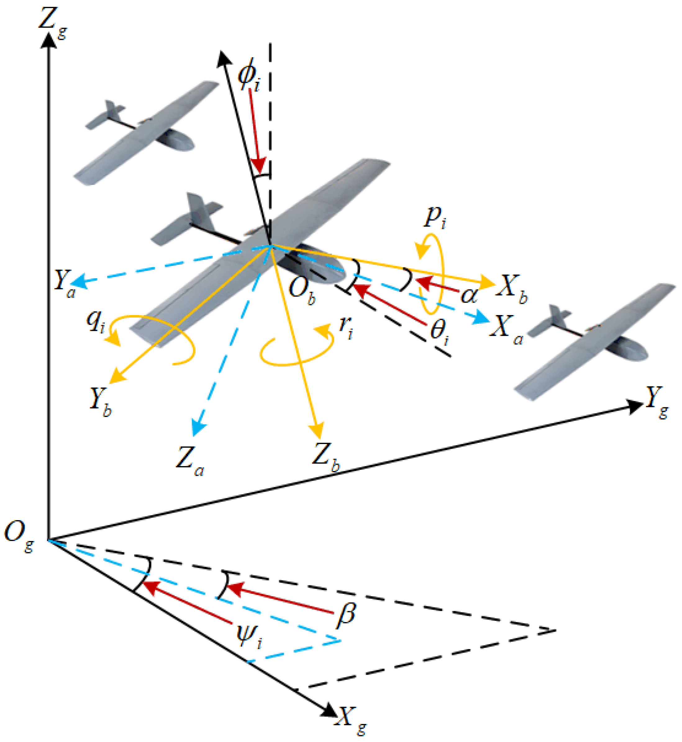
Figure 2. Schematic diagram of the fixed-wing UAV showing the coordinate systems and key physical parameters.
Drones 09 00715 g002
A detailed explanation of these key state variables will be provided below, alongside their corresponding expressions. Then we consider a formation composed of N identical fixed-wing UAVs. The six-degree-of-freedom (6-DOF) dynamic model of the i-th fixed-wing UAV is described as follows [37].

2.1.1. Velocity Layer

Let the velocity vector of the i-th UAV in the body frame be denoted as v i = u i , v i , w i T . The velocity-layer dynamic model, governing the translational motion, is given by Equations (1) and (2)
I ˙ i = R 1 ( φ i ) v i
v ˙ i = ω i × v i + P i m i + R 1 T ( φ i ) g + F i m i + d v i
where Equation (1) is the kinematic equation for position. It describes how the UAV’s position I i in the ground frame evolves based on its velocity v i in the body frame, through the coordinate transformation matrix R 1 ( φ i ) . Equation (2) is the kinetic equation for velocity (or force equation), derived from Newton’s second law. It describes how the velocity vector changes due to thrust P i , gravity g , aerodynamic forces F i , gyroscopic effects, and disturbances d v i . To be specific, m i represents the mass of the UAV, I i = [ x i , y i , z i ] T denotes the position vector in the ground coordinate system, φ i = [ ϕ i , θ i , ψ i ] T is the attitude angle vector, ω i = [ p i , q i , r i ] T is the angular velocity vector, P i = [ P x i , 0 , 0 ] T signifies the thrust vector, g = [ 0 , 0 , g ] T is the gravitational acceleration, and d v i represents unknown external disturbances. Besides, as can be seen from Figure 2, the yaw angle ψ i is the angle between the projection of the body X b -axis onto the ground plane ( O g X g Y g ) and the ground X g -axis; the pitch angle θ i is the angle between the body X b -axis and the ground plane; the roll angle ϕ i is the angle of rotation about the body X b -axis itself; the angle of attack α is the angle between the projection of the air-velocity vector (the wind X a -axis) onto the body’s plane of symmetry ( O b X b Z b ) and the body X b -axis; the sideslip angle β is the angle between the air-velocity vector itself and the body’s plane of symmetry. The matrix R 1 ( φ i ) transforms coordinates from the body frame to the ground frame and is expressed as
R 1 ( φ i ) = C ψ i C θ i S ψ i S ϕ i + C ψ i S θ i S ϕ i S ψ i S ϕ i + C ψ i S θ i C ϕ i S ψ i C θ i C ψ i C ϕ i + S ψ i S θ i S ϕ i C ψ i S ϕ i + S ψ i S θ i C ϕ i S θ i C θ i S ϕ i C θ i C ϕ i
where the notation S a i and C a i is introduced as a shorthand, denoting sin ( a i ) and cos ( a i ) respectively. Here, “a” is a generic placeholder for any angle. This convention is used throughout the paper: For example, C ψ i means cos ( ψ i ) , S θ i means sin ( θ i ) , and C α i means cos ( α i ) . The aerodynamic force vector F i is given by
F i = q ¯ i S i R 3 1 α i , β i K D i , K Y i , K L i T
where S i is the wing area, q ¯ i = 0.5 ρ V i a 2 is the dynamic pressure, ρ is the air density, and K D i , K Y i , K L i are the drag coefficient, side force coefficient, and lift coefficient, respectively. The transformation matrix R 3 ( α i , β i ) , which relates the body frame to the wind frame, is defined as
R 3 α i , β i = C α i C β i S β i S α i C β i C α i S β i C β i S α i S β i S α i 0 C α i

2.1.2. Attitude Layer

Based on the definitions and relationships between attitude angles and angular rates, the attitude-layer dynamic model is constructed as
φ ˙ i = R 2 1 ( φ i ) ω i
J i ω ˙ i = ω i × J i ω i + N b i + C ( δ i ) δ i + J i d ω i
where δ i = [ δ a i , δ e i , δ r i ] T is the control surface input vector; d ω i denotes unknown external disturbances; R 2 ( φ i ) is the transformation matrix that projects angular rates onto attitude angle derivatives, expressed as
R 2 φ i = 1 0 S ψ i 0 C ψ i S ψ i C θ i 0 S θ i C ψ i C θ i
The inertia tensor J i , defined in the body frame x-z plane, is given by
J i = J x x i 0 J x z i 0 J y y i 0 J z x i 0 J z z i
The control effectiveness matrix C ( δ i ) is formulated as
C δ i = q ¯ i S i B i C l δ a i 0 q ¯ i S i B i C l δ r i 0 q ¯ i S i C ¯ i c m δ e i 0 q ¯ i S i B i C n δ a i 0 q ¯ i S i B i C n δ r i
The moment vector N b i is described by
N b i = q ¯ i S i b i K l i , c ¯ i K M i , b i K n i T
where b i is the wingspan; K l i , K M i , K n i , C l δ a i , C l δ r i are dimensionless coefficients; and C l δ a i , C m δ e i , C n δ r i correspond to the aerodynamic coefficients along the x, y, and z axes of the body frame, respectively.

2.2. Graph Theory

The communication topology among multiple UAVs is represented using an undirected graph G = ( V , E , A ) , where V is a finite non-empty set of nodes, with each node v i representing a UAV. The edge set E V × V indicates information exchange relationships between UAVs. If the i-th UAV and the j-th UAV can exchange information mutually, it is denoted by ( n i , n j ) E , where E implies bidirectional communication. The weighted adjacency matrix A , corresponding to the topological graph G , describes the communication topology. The elements a i j of the matrix are defined as follows: if ( n i , n j ) E , then a i j > 0 ; otherwise, a i j = 0 . Furthermore, the Laplacian matrix L is defined as L = D A , where D is the in-degree matrix of the undirected graph G , and its diagonal elements d i satisfy d i = j = 1 N a i j .
Assumption 1
([38]). The communication topology G is connected. That is, for any two nodes n i and n j ( n i , n j V , i j ), there exists a path such that information can be relayed between them. This assumption guarantees that all UAVs can communicate with each other, either directly or indirectly.
Assumption 2
([38]). At least one UAV (typically designated as the leader or root node) has access to the global desired command ξ d ( t ) , which encompasses both the desired attitude and velocity profiles. This command can be propagated through the communication topology G to all other UAVs in the formation.
Remark 1.
These two assumptions are essential for the multi-UAV system to achieve distributed coordination under the communication topology G . Assumption 1 (connectivity) guarantees that information can propagate throughout the entire network, enabling state consensus among all UAVs. Assumption 2 (command reachability) ensures that the global desired command ξ d ( t ) (attitude and velocity) is injected into the system and distributively available to all agents. Together, they establish the foundational communication and command-following capabilities required for cooperative control. Similar assumptions are commonly adopted in the literature on multi-agent systems, see, e.g., [21,22].

2.3. Interval Type-2 Fuzzy Logic System

The footprint of uncertainty (FOU), bounded by the upper and lower membership functions, is referred to as an interval type-2 fuzzy set. The selected interval type-2 fuzzy rule is as follows:
IF x is F ˜ 1 i , THEN y is G ˜ i , for i = 1 , 2 , , N . Here, x denotes the input vector of the interval type-2 fuzzy logic system (IT2FLS), and y is the system output. For each i and j, F ˜ j i and G ˜ i represent the antecedent and consequent fuzzy sets, respectively. Using the Karnik–Mendel algorithm, the left and right endpoints of the output interval, y l and y r , are computed as
y l = i = 1 N f ̲ i ( θ l i ) i = 1 N f ̲ i ( θ l i ) , y r = i = 1 N f ¯ i ( θ r i ) i = 1 N f ¯ ( θ r i ) i
where f ¯ i ( θ r i ) and f ̲ i ( θ l i ) denote the firing strengths of the upper and lower membership functions, respectively. The adaptive parameter vector is defined as θ , and the Bayesian equation is selected as θ = θ l + θ r 2 , where θ l = [ θ l 1 , θ l 2 , , θ l N ] T , θ r = [ θ r 1 , θ r 2 , , θ r N ] T , satisfying θ l i θ r i for i = 1 , 2 , , N . Consequently, the defuzzified output of the IT2FLS is expressed as
y = y l + y r 2 = H T ( s l ( Θ ) + s r ( Θ ) ) 2 = H T S ( Θ )
Lemma 1
([39]). For any nonlinear system defined on a compact set Ω x , an interval type-2 fuzzy logic system can uniformly approximate any real continuous function a ( Θ ) on Ω x to arbitrary accuracy. Thus, the following decomposition exists
a ( Θ ) = W T S ( Θ ) + ε ( Θ )
where W is the ideal weight vector, S ( Θ ) is the bounded fuzzy basis function vector, and ε ( Θ ) is the approximation error, for which there exists a positive constant ε ¯ such that | ε ( Θ ) | ε ¯ . The IT2FLS, as formulated in Equation (14), is employed to estimate the unknown disturbances in the multi-UAV system. This approach is necessitated by the multivariable nonlinear nature of the fixed-wing UAV dynamics, given by Equations (1), (2), (6) and (7), which stems primarily from the trigonometric functions in the coordinate transformations and the Coriolis/centrifugal coupling terms. In this study, Lemma 1 is applied by constructing an independent IT2FLS to approximate the unknown nonlinear terms for each state variable (i.e., velocity and the three attitude angles) of each UAV in the formation. The universal approximation property holds for the aggregated system, as the dynamics are addressed through a decentralized control scheme, with the approximation being performed locally for each agent.

2.4. Prescribed-Time Stability Concept

Definition 1
([40]). Consider the nonlinear system x ˙ = f ( x , t ) , x ( 0 ) = x 0 , where x R n is the state vector. The system is said to be prescribed-time stable if there exists a user-defined time T f > 0 such that for any initial condition x 0 in a domain of interest D , the trajectory x ( t ) converges to the origin (or a small neighborhood) within the prescribed time T f , i.e., lim t T f x ( t ) = 0   ( o r x ( t ) ε for t T f ) . The key feature is that T f is independent of initial conditions x 0 and system parameters, and can be arbitrarily assigned by the designer.
Definition 2.
A prescribed-time performance function (PTPF) η ( t ) satisfies the following conditions [20]:
  • η ( t ) is positive and monotonically decreasing over t [ 0 , T f ) ;
  • lim t T f η ( t ) = η > 0 and η ( t ) η for all t T f ;
  • η ˙ ( t ) and η ¨ ( t ) are bounded and piecewise continuous.
Based on Definition 2, the prescribed-time performance function is selected as
η ( t ) = ( η 0 η ) exp t T f t + η , t [ 0 , T f ) η , t [ T f , )
As illustrated in Figure 3, the initial value η 0 determines the starting bound, the steady-state value η sets the final asymptotic bound, and the parameter T f prescribes the exact convergence instant. The function decreases smoothly from η 0 to η during t [ 0 , T f ) , ensuring controlled transient performance with accelerated convergence as t approaches T f . Specifically, as shown in Figure 3, an increase in parameter η 0 leads to a higher initial value of the performance function, an increase in parameter η results in a higher steady-state value, and an increase in parameter T f causes an extension of the convergence time.

2.5. Control Objective

Consider a multi-UAV system composed of N fixed-wing UAVs. The system is subject to external disturbances and employs an undirected communication topology for information exchange. Given the desired velocity command V r and attitude command φ r to be tracked, the control objective is to design a prescribed-time dynamic self-triggered controller for both the velocity and attitude loops of the UAV system to achieve the following outcomes.
  • All closed-loop signals of the multi-UAV formation system are guaranteed to be Semi-Globally Uniformly Ultimately Bounded (SGUUB). Furthermore, both the velocity tracking error e V i and the attitude tracking error e φ i converge to compact sets around the origin within a predefined settling time T, which is independent of initial conditions.
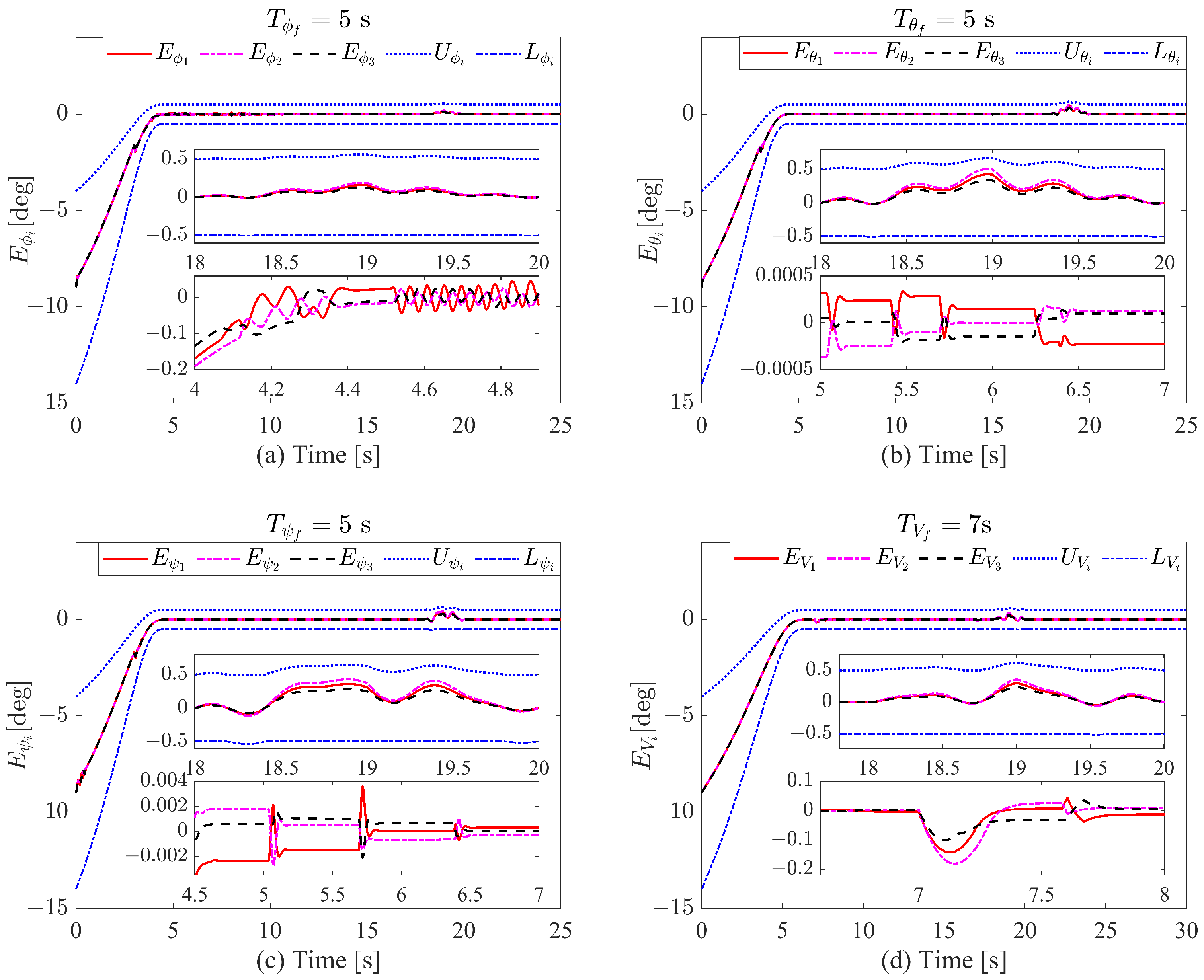
  • The transformed tracking errors are guaranteed to remain strictly within the envelopes defined by the self-adjusting boundary performance functions throughout the entire operation. Specifically, the velocity error is constrained by V i = E V i ( t ) | L V i ( t ) < E V i ( t ) < U V i ( t ) and the attitude errors are constrained by m i = E m i ( t ) | L m i ( t ) < E m i ( t ) < U m i ( t ) , m = ϕ , θ , ψ .
  • The designed Dynamic Self-Triggered Mechanism (DSTM) strictly excludes Zeno behavior, ensuring a positive minimum inter-event time. Moreover, it eliminates the necessity for continuous monitoring of neighboring UAVs’ states, thereby significantly reducing both communication bandwidth usage and onboard computational resource consumption.
Assumption 3
([41]). The reference commands, namely the desired velocity V r and the attitude trajectory φ r , are designed to be continuously differentiable. Moreover, it is assumed that their corresponding second-order time derivatives, V ¨ r and φ ¨ r , exist and remain bounded for all time.
Lemma 2
([42]). For any two vectors x , y R N , if there existc > 0 and p , q 1 such that ( p 1 ) ( q 1 ) = 1 , then it holds that x T y c p p x p + 1 q c q y q .
Remark 2.
This inequality (Young’s inequality) is extensively used in the Lyapunov stability analysis for the multi-UAV system. It is applied to decouple cross-terms that appear in the time derivative of the Lyapunov function candidate. This includes terms within the error dynamics of a single UAV as well as coupling terms between neighboring UAVs that arise from the distributed formation control law. Its application is crucial for handling the interconnected nature of the multi-agent system and proving overall system stability.

3. Dynamic Self-Triggered Controller Design

3.1. Self-Adjusting Boundary Performance Function

Based on (15), the boundary performance functions are further designed. The corresponding upper bound function P 1 ( t ) and lower bound function P 2 ( t ) are designed as follows
P 1 ( t ) P 2 ( t ) T = sign e ( 0 ) η ( t ) η 1 , 1 T + η ( t ) p 1 , p 2 T
where p 1 , p 2 0 , 1 . Then for P 1 ( t ) , P 2 ( t ) , t 0 , , the following three cases exist
  • P 1 ( t ) = ( η ( t ) η ) + p 1 η ( t ) , P 2 ( t ) = ( η ( t ) η ) p 2 η ( t ) , e ( 0 ) > 0 ;
  • P 1 ( t ) = ( η ( t ) η ) + p 1 η ( t ) , P 2 ( t ) = ( η ( t ) η ) p 2 η ( t ) , e ( 0 ) < 0 ;
  • P 1 ( t ) = p 1 η ( t ) , P 2 ( t ) = p 2 η ( t ) , e ( 0 ) = 0 .
where P 1 ( t ) serves as the upper bound and P 2 ( t ) serves as the lower bound.
Integrating the above three cases, it is known that P 2 ( t ) < P 1 ( t ) holds for t 0 . Therefore, P 1 ( t ) and P 2 ( t ) can be used as the time-varying upper and lower bound functions for the error e ( t ) , respectively. From Definition 1, it follows that the designed boundary performance functions P 1 ( t ) and P 2 ( t ) are monotonically decreasing over t [ 0 , T f ) s and remain constant at P 1 ( t ) = η p 1 and P 2 ( t ) = η p 2 for t [ T f , + ) s. Furthermore, all three cases satisfy: lim t T f P 1 ( t ) = η p 1 , lim t T f P 2 ( t ) = η p 2 , lim t T f + P 1 ( t ) = η p 1 , and lim t T f + P 2 ( t ) = η p 2 .
Furthermore, considering that the tracking error may surge due to external disturbances acting on the UAV system when using the performance function for envelope constraint, if the tracking error exceeds the boundaries of the performance function, it may cause system divergence. Therefore, based on Equation (16), a self-adjusting boundary performance function is designed to adaptively modify the boundaries when the tracking error approaches the performance function boundaries. The self-adjusting boundary performance function is designed as follows:
U ( t ) , L ( t ) T = P 1 ( t ) , P 2 ( t ) T + Q 1 ( t ) , Q 2 ( t ) T
where Q 1 ( t ) , Q 2 ( t ) T = A tanh B 1 ( t ) , tanh B 2 ( t ) T , Q 1 ( t ) and Q 2 ( t ) are the adaptive adjustment amounts for the upper and lower boundaries, respectively, A = diag { q 1 , q 2 } , q 1 , q 2 > 0 , U ( t ) and L ( t ) are the adjusted upper and lower boundaries, respectively. For i = 1 , 2 , the adaptive update laws for the parameters B i ( t ) are designed as:
B ˙ i ( t ) = c i 1 B i ( t ) + c i 2 G i ( t ) , B i ( 0 ) = 0
where G 1 ( t ) = sign U e Δ 1 ( U e Δ ) , G 2 ( t ) = sign e L Δ 1 e L Δ , c i 1 and c i 2 are positive constants, Δ is a small positive constant representing a boundary threshold. Equation (18) indicates that the boundary is adaptively adjusted when U e < Δ or e L < Δ ; when U e Δ or e L Δ , the boundary adjustment values rapidly decay to zero.
Due to the uncertainty of the initial values of the UAV’s velocity and attitude, when the initial values differ significantly from the commanded values, the initial error may exceed the boundaries of the self-adjusting performance function. Therefore, the performance function parameters need to be reselected each time the initial values change, which reduces the generality of the preset performance function method. To solve this problem, the following error transformation function is introduced:
E ( t ) = e ( t ) h S ( t )
where S ( t ) = t s t t s t t s , t s , t 0 , t s 0 , t t s , , h = e ( 0 ) P 1 ( 0 ) + P 2 ( 0 ) P 1 ( 0 ) + P 2 ( 0 ) 2 2 . Through the above transformation, it can be known that E ( 0 ) = P 1 ( 0 ) + P 2 ( 0 ) P 1 ( 0 ) + P 2 ( 0 ) 2 2 L ( 0 ) , U ( 0 ) , thus the singularity problem caused by initial conditions is eliminated. Furthermore, to ensure L ( t ) < E ( t ) < U ( t ) holds for t 0 , the following state transformation function is introduced
υ ( t ) = ln Π ( t ) 1 Π ( t )
where Π ( t ) = E ( t ) L ( t ) E ( t ) L ( t ) D ( t ) D ( t ) 0 , 1 is the normalized error, and D ( t ) = U ( t ) L ( t ) .
Lemma 3.
For any h such that the initial state E ( 0 ) satisfies L ( 0 ) < E ( 0 ) < U ( 0 ) , if υ ( t ) remains bounded, then L ( t ) < E ( t ) < U ( t ) holds for all t 0 .
Proof. 
Since L ( 0 ) < E ( 0 ) < U ( 0 ) , Π ( 0 ) 0 , 1 is well-defined. Assume there exists t 1 > 0 such that E ( t 1 ) L ( t 1 ) or E ( t 1 ) U ( t 1 ) , then due to the continuity of E ( t ) , U ( t ) and L ( t ) , and noting that ( E ( 0 ) L ( 0 ) ) ( E ( t 1 ) L ( t 1 ) ) 0 and ( U ( 0 ) E ( 0 ) ) ( U ( t 1 ) E ( t 1 ) ) 0 , the Intermediate Value Theorem implies that there must exist t 1 0 , t 1 such that E ( t 1 ) L ( t 1 ) = 0 or E ( t 1 ) U ( t 1 ) = 0 , i.e., E ( t 1 ) = L ( t 1 ) or E ( t 1 ) = U ( t 1 ) . At this point, Π ( t ) Π ( t ) 1 Π ( t ) 1 Π ( t ) equals zero or tends to infinity. Combining with Equation (20), it follows that υ ( t ) is unbounded, which contradicts the assumption that υ ( t ) remains bounded. Therefore, L ( t ) < E ( t ) < U ( t ) holds for all t 0 . Lemma 3 is thus proved. □
The lemma above is fundamental to guaranteeing prescribed performance for the entire formation. The result of Lemma 3 applies independently and simultaneously to every transformed tracking error in the system. That is, for the i-th UAV ( i = 1 , . . . , N ), if υ V i ( t ) , υ ϕ i ( t ) , υ θ i ( t ) , and υ ψ i ( t ) are bounded, then the velocity and attitude tracking errors for all UAVs will strictly satisfy their respective performance boundaries L * i ( t ) < E * i ( t ) < U * i ( t ) for all time. This allows the decentralized prescribed-time control objective to be achieved for the multi-UAV system as a whole.
Remark 3.
It should be noted that the formulations of the self-adjusting boundary performance function and error transformation presented in this section are described without explicit subscript notation for notational simplicity, representing the general methodological framework. However, in the actual multi-UAV system implementation, each performance function and transformation must be distinctly defined for each state variable of every UAV. Specifically, for the velocity state of the i-th UAV, the corresponding subscript should be V i (e.g., e V i ( t ) , U V i ( t ) , L V i ( t ) , υ V i ( t ) ). Similarly, for the attitude angles ( ϕ , θ , ψ ), the corresponding subscript for the i-th UAV should be ϕ i , θ i , ψ i , respectively (e.g., e ϕ i ( t ) , U ϕ i ( t ) , L ϕ i ( t ) , υ ϕ i ( t ) ; e θ i ( t ) , U θ i ( t ) , L θ i ( t ) , υ θ i ( t ) ; e ψ i ( t ) , U ψ i ( t ) , L ψ i ( t ) , υ ψ i ( t ) ). This subscript notation will be explicitly adopted in the subsequent controller design and stability analysis sections to ensure clarity and precision.
Based on the aforementioned results, the velocity and attitude errors are further transformed, yielding the following outcomes:
  • Velocity Layer Error Transformation
    Consider the velocity error as e v = v v r . The velocity error is transformed and normalized into Π V i ( t ) . Using the state transformation function Equation (20), the transformed state is obtained as
    υ V i ( t ) = ln Π V i 1 Π V i
    where Π V i = E V i ( t ) L V i ( t ) E V i ( t ) L V i ( t ) D V i D V i ( t ) , E V i ( t ) = e V i ( t ) h V i S V i ( t ) , h V i = V ˜ i ( 0 ) P V i 1 ( 0 ) + P V i 2 ( 0 ) P V i 1 ( 0 ) + P V i 2 ( 0 ) 2 2 and S V i ( t ) , P V i 1 ( t ) and P V i 2 ( t ) are functions to be designed.
    Then derivative Equation (21), one has
    υ ˙ V i = F V i E ˙ V i + ς V i
    where F V i = 1 D V i Π V i ( 1 Π V i ) , ς V i = 1 D V i L V i U ˙ V i U V i L ˙ V i E V i D ˙ V i .
  • Attitude Layer Error Transformation
    Consider the attitude error e φ i = φ i φ r , the attitude error is transformed and normalized into Π φ i l ( t ) . Using the state transformation function Equation (20), the transformed state is obtained as
    υ φ i l ( t ) = ln Π φ i l 1 Π φ i l
    where for l = 1 , 2 , 3 , Π φ i l = E φ i l ( t ) L φ i l ( t ) D φ i l ( t ) , h φ i l = P φ i l 1 ( 0 ) + P φ i l 2 ( 0 ) 2 + l ˜ i ( 0 ) and S φ i l ( t ) , P φ i l 1 ( t ) and P φ i l 2 ( t ) are functions to be designed.
Define υ φ i = υ φ i 1 , υ φ i 2 , υ φ i 3 T , integrating Equation (23) yields
υ ˙ φ i = F φ i E ˙ φ i + ς φ i
where F φ i = diag { F φ i 1 , F φ i 2 , F φ i 3 } , E ˙ φ i = E φ i 1 , E φ i 2 , E φ i 3 T , ς φ i = ς φ i 1 , ς φ i 2 , ς φ i 3 T , and for l = 1 , 2 , 3 :, F φ i l = 1 D φ i l Π φ i l 1 Π φ i l , ς φ i l = 1 D φ i l L φ i l U ˙ φ i l U φ i l L ˙ φ i l E φ i l D ˙ φ i l .

3.2. Dynamic Self-Triggered Communication Mechanism

In order to achieve formation control for the UAV swarm, each UAV relies on the communication topology network to transmit its own state information and receive state data from neighboring UAVs.

3.2.1. Velocity Layer Communication Mechanism Design

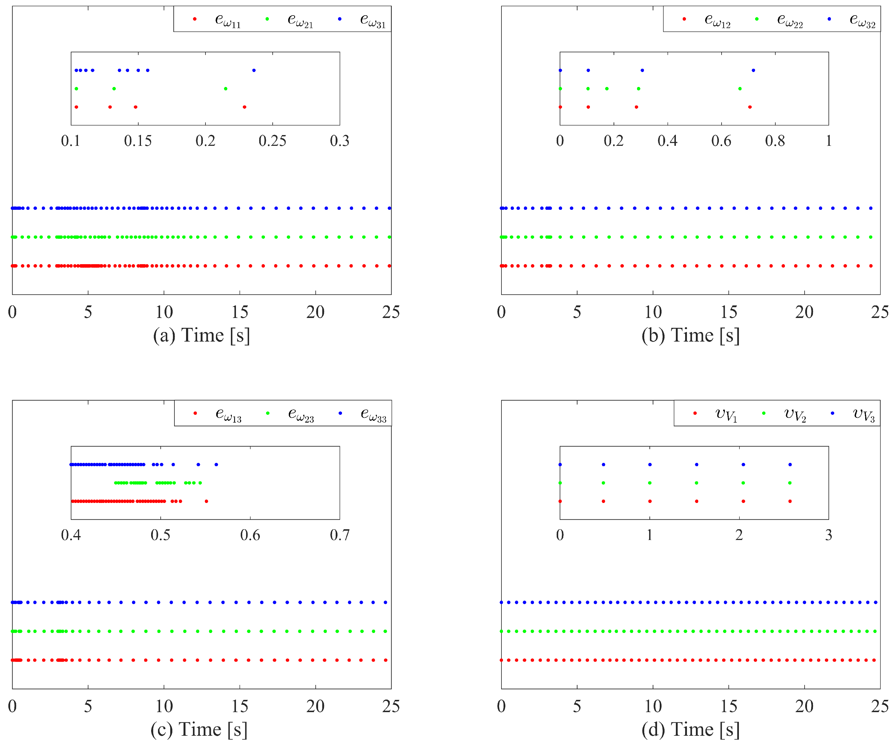
To improve the communication efficiency of the multi-UAV system and minimize resource wastage, the velocity layer DETM is designed for t t r i V i , t r i + 1 V i as follows:
t r i + 1 V i = inf t σ V i 1 ξ V i 2 ( t ) ζ V i + σ V i 2 σ V i 3 + σ V i 4 υ V i ( t r i V i ) & t > t r i V i
where ξ V i = υ V i ( t r i V i ) υ V i ( t ) represents the difference between the velocity layer sampling instant and the continuous-time error. σ V i 1 is a parameter to be designed later, while σ V i 2 , σ V i 3 , and σ V i 4 are positive design parameters. The adaptive update law for the internal dynamic variable ζ V i is then formulated as:
ζ ˙ V i = V i ζ V i σ V i 1 ξ V i 2 + σ V i 2 σ V i 3 + σ V i 4 υ V i ( t r i V i )
Based on the dynamic triggering mechanism defined in Equation (25), the velocity layer dynamic self-triggered mechanism (DSTM) is formulated as follows:
t r i + 1 V i = t r i V i + T r i V i T r i V i = 1 M V i max σ V i 2 σ V i 1 σ V i 3 + σ V i 4 υ V i ( t r i V i ) + ζ ̲ V i ( t r i V i ) σ V i 1
where M V i max is the upper bound of the derivative of the velocity error, which will be derived in the subsequent stability analysis, and ζ ̲ V i ( t r i V i ) is a lower-bound function related to the internal dynamic variable ζ V i at the latest triggering instant t r i V i . The detailed design process of these parameters will be elaborated in the subsequent sections.

3.2.2. Attitude Layer Communication Mechanism Design

Define e ω i = ω i ω d , where ω d represents the virtual control law for the attitude layer. Similar to the velocity layer, for t t r i ω i l , t r i + 1 ω i l , the attitude layer DETM is formulated as:
t r i + 1 ω i l = inf t σ ω i l 1 ξ ω i l 2 ζ ω i l + σ ω i l 2 σ ω i l 3 + σ ω i l 4 e ω i l ( t r i ω i l ) & t > t r i ω i l
where for l = 1 , 2 , 3 , ξ ω i l = e ω i l ( t r i ω i l ) e ω i l ( t ) , e ω i l is the l-th element of e ω i . σ ω i l 1 is a parameter to be determined later, while σ ω i l 2 , σ ω i l 3 , and σ ω i l 4 are positive design parameters. The adaptive update law for the internal dynamic variable ζ ω i l is formulated as
ζ ˙ ω i l = ω i l ζ ω i l σ ω i l 1 ξ ω i l 2 + σ ω i l 2 σ ω i l 3 + σ ω i l 4 e ω i l ( t r i ω i l )
Based on the dynamic triggering mechanism defined in Equation (28), the attitude layer DSTM is formulated as follows:
t r i + 1 ω i l = t r i ω i l + T r i ω i l T r i ω i l = 1 M ω i l max σ ω i l 2 σ ω i l 1 σ ω i l 3 + σ ω i l 4 υ ω i l ( t r i ω i l ) + ω i l ( t r i ω i l ) σ ω i l 1
where M ω i l max is the upper bound of the derivative of the l-th angular velocity error component ( l = 1 , 2 , 3 corresponding to p , q , r ), which will be derived later, and ζ ̲ ω i l ( t r i ω i l ) is a lower-bound function related to the internal dynamic variable ζ ω i at the latest triggering instant t r i ω i . The detailed design process of these parameters will be elaborated on in the subsequent sections.
Remark 4.
The designed DETM (Equations (25) and (26)) is employed to establish an appropriate triggering threshold and to determine the inter-event intervals for the subsequent DSTM. The proposed DSTM (Equation (27)) constitutes an innovative communication framework that incorporates the advantages of traditional self-triggered schemes by eliminating the need for continuous state monitoring while maintaining satisfaction of the triggering conditions. Importantly, this integration is not a simple combination of the two mechanisms. It requires the establishment of a precise relationship between the system state values V ˜ i ( t k i V i ) and the inter-event intervals through the triggering threshold, as defined by the inequality condition in Equation (25). Meanwhile, it must be ensured that the state error consistently satisfies the prescribed triggering constraints at each subsequent triggering instant. The DSTM (Equation (27)) effectively refines the triggering threshold through the inclusion of dynamic variables ( ζ V i in Equation (26)), thereby reducing the frequency of network signal sampling. At the same time, it eliminates the restrictive assumption of continuous state monitoring, requiring only the current state information V ˜ i ( t k i V i ) to determine the next sampling instant. This dynamic modulation of the sampling frequency is deliberately designed to ensure the convergence of the multi-UAV system while optimizing the utilization of both network communication and sensor resources.
Remark 5.
The enhanced control accuracy and reduced communication frequency achieved by the proposed DSTCM originate from its fundamental redesign of the sampling-control relationship. Compared to the static event-triggering communication mechanism (SETCM)’s conservative static threshold—which necessitates worst-case design leading to excessive triggering during normal operation—DSTCM incorporates an internal dynamic variable that adaptively adjusts the triggering threshold. This adaptation relaxes the threshold during large error fluctuations to prevent Zeno behavior and tightens it near equilibrium, enabling longer transmission intervals without sacrificing accuracy. Meanwhile, unlike DETCM that requires continuous state monitoring—forcing a trade-off between sampling rate and performance—DSTCM employs self-triggering to compute subsequent instants directly from previous states, eliminating inter-trigger monitoring. This permits controller synthesis based on precise inter-trigger interval prediction, where control laws proactively compensate for state evolution during quiet periods, thereby minimizing error growth. Ultimately, DSTCM synergizes DETM’s adaptive thresholding with STM’s predictive compensation, overcoming the continuous monitoring bottleneck to establish a refined balance between communication efficiency and control precision.

3.3. Controller Design and Stability Analysis with Zeno Behavior Exclusion

3.3.1. Velocity-Layer Controller

Define the scalar speed of the velocity vector v i as V i a , which satisfies V i a = v i = v i T v i . Differentiating the scalar speed V i based on Equation (2) yields
V ˙ i a = χ V i P x i + V i a 1 v i T R 1 T g + m i 1 N b i + V i 1 v i T d V i
where χ V i a = u i m i V i a , and the property v i T × v i = 0 has been utilized.
Based on Equations (19) and (31), differentiating E V i yields
E ˙ V i = χ V i P x i + Ω V i + V i a 1 v i T d V i
where Ω V i = V i a 1 v i T R 1 T g + m i 1 N b i V ˙ r h V i S ˙ V i .
Substituting Equation (32) into Equation (22) yields
υ ˙ V i = F V i χ V i P x i + Ω V i + ς V i + V i a 1 F V i v i T d V i
For the external disturbance term V i a 1 F V i v i T d V i in the velocity layer, a second-order fuzzy logic system is employed, yielding
υ V i F V i V i a 1 v i T d V i = υ V i F V i V i a 1 v i T W V i 1 T S V i 1 + ε V i 1 W V i 2 T S V i 2 + ε V i 2 W V i 3 T S V i 3 + ε V i 3 = υ V i F V i V i a 1 l = 1 3 v i a W V i a T S V i a + l = 1 3 v V i a ε V i a
where v i l is an element of the vector v i , l = 1 , 2 , 3 , and | ε V i l | ε ¯ V i l .
According to Lemma 2, Equation (34) satisfies
υ V i F V i v i l V i W V i l T S V i l υ V i 2 F V i 2 v i l 2 Φ V i S V i l T S V i l 2 l V i 1 2 V i a 2 + l V i 1 2 2
υ V i F V i v i l V i a ε V i l υ V i 2 F V i 2 v i l 2 2 l V i 2 2 V i a 2 + l V i 2 2 ε ¯ V i l 2 2
where l V i 1 and l V i 2 are positive constants to be selected, whose values directly affect the magnitude of the final bounded estimation. In simulations, they are determined through numerical experiments to ensure the system maintains good performance at all times.
From Equations (35) and (36), we obtain
υ V i F V i V i a 1 v i T d V i F V i 2 υ V i Φ V i v i T Υ V i 2 l V i 1 2 V i a 2 + υ V i v i T v i 2 l V i 2 2 V i a 2 + l V i 1 2 2 + l V i 2 2 ε ¯ V i 2 2
where Υ V i = υ V i v V i 1 S V i 1 T S V i 1 , v V i 2 S V i 2 T S V i 2 , v V i 3 S V i 3 T S V i 3 T .
The velocity-layer cooperative controller based on the DSTM is designed as follows:
P x i = χ V i 1 λ V i F V i 1 j = 1 N a i j υ V i ( t r i V i ) υ V j ( t r j V j ) + Ω V i + ς V i + V i
where V i = F V i Φ ^ V i v i T Υ V i 2 l V i 1 2 V i a 2 + F V i v i T v i 2 l V i 2 2 V i a 2 + k V i F V i 1 υ V i + F V i 1 υ V i 1 l = 1 3 l V i 1 2 2 + l V i 2 2 ε ¯ V i l 2 2 .
Remark 6.
In this study, controller parameters such as k v i , l v i 1 and l v i 2 are tuned through numerical experiments following a systematic procedure to ensure system stability and satisfactory transient performance. The tuning process adheres to the following general principles: Initially, parameters are selected based on the Lyapunov stability conditions derived in the theoretical analysis, ensuring that the closed-loop system meets the basic stability requirements. Specifically, this involves ensuring that k v i , l v i 1 and l v i 2 are chosen to be small positive values. Subsequently, the parameters are iteratively refined by observing the system’s response to step changes and external disturbances in simulations, in order to achieve the desired transient performance metrics. As a general guideline, increasing the control gains (e.g., k v i ) typically accelerates the system’s convergence rate, but may lead to increased overshoot or control oscillations. Conversely, decreasing these gains enhances response smoothness and robustness against measurement noise, but at the cost of slower response times. A balance must be sought to meet the specific performance requirements of the multi-UAV formation. Furthermore, due to constraints imposed by the performance function, it is essential to maintain the system’s state within predefined bounds during the tuning process. When k v i v is increased, the amplitude of the performance function can be relaxed appropriately; conversely, when k v i is decreased, the amplitude of the performance function can be tightened. Throughout this process, a balance must be struck between the system’s responsiveness and stability.
Furthermore, define the disturbance parameter satisfying Φ ˜ V i = Φ ^ V i Φ V i , where Φ ˜ V i is the estimation error and Φ ^ V i is the estimated value. The adaptive update law for parameter Φ ^ V i is designed as
Φ ^ ˙ V i = F V i 2 υ V i v i T Υ V i 2 l V i 1 2 V i a 2 o V i Φ ^ V i
where o V i is a positive constant to be designed.
Theorem 1.
Consider a multi-UAV system comprising N six-degree-of-freedom fixed-wing UAVs. For the velocity subsystem governed by Equations (1) and (2), under the event-triggered velocity cooperative controller (38), the DSTM (27), and the adaptive update law (39), and based on Lemma 3, the following properties are guaranteed
  • All signals within the velocity closed-loop system are semi-globally uniformly ultimately bounded (SGUUB). Moreover, the synchronized velocity tracking error V ˜ i converges to a small residual set around the origin within a preassigned time T.
  • The transformed error υ V i remains strictly confined within the prescribed time-varying asymmetric constraints defined by the performance functions throughout the entire tracking process.
  • The proposed control strategy significantly reduces the communication burden and sensor resource consumption in the velocity layer. Furthermore, the existence of a positive minimum inter-event time excludes Zeno behavior, ensuring the practical implementability of the algorithm.
Proof. 
A Lyapunov function candidate is constructed as L 1 = 1 2 i = 1 N υ V i 2 + 1 2 i = 1 N Φ ˜ V i 2 , differentiating L 1 along Equation (22) yields
L ˙ 1 = i = 1 N υ V i υ ˙ V i + i = 1 N Φ ˜ V i Φ ^ ˙ V i = i = 1 N υ V i F V i χ V i P i + υ V i F V i Ω V i + ς V i + υ V i F V i V i a 1 v i T d V i + i = 1 N Φ ˜ V i Φ ^ ˙ V i
Substituting Equation (37) into Equation (40) yields
L ˙ 1 i = 1 N υ V i F V i χ V i P x i + υ V i F V i Ω V i + ς V i + i = 1 N F V i 2 υ V i Φ ^ V i v V i T Υ V i 2 l V i 1 2 V i a 2 + i = 1 N F V i 2 υ V i v V i T v V i 2 l V i 2 2 V i a 2 + i = 1 N Φ ˜ V i Φ ^ ˙ V i F V i 2 υ V i Φ ˜ V i v V i T Υ V i 2 l V i 1 2 V i l 2 + i = 1 N l = 1 3 l V i 1 2 2 + l V i 2 2 ε ¯ V i l 2 2
Substituting the thrust control law Equation (38) and the adaptive parameter update law Equation (39) into Equation (41) yields
L ˙ 1 i = 1 N υ V i λ V i j = 1 N a i j υ V i ( t r i V i ) υ V j ( t r j V j ) i = 1 N o V i Φ ^ V i Φ ˜ V i k V i i = 1 N υ V i 2
Considering ξ V i = υ V i ( t r i V i ) υ V i ( t ) , the term i = 1 N υ V i λ V i j = 1 N a i j υ V i ( t r i V i ) υ V j ( t r j V j ) in Equation (42) can be processed as
i = 1 N υ V i λ V i j = 1 N a i j υ V i ( t r i V i ) υ V j ( t r j V j ) λ max ( L ) i = 1 N λ V i υ V i υ V i ( t r i V i ) = λ max ( L ) i = 1 N λ V i υ V i ξ V i + λ V i υ V i 2
According to Lemma 2, the term λ max ( L ) i = 1 N λ V i υ V i ξ V i can be further processed as
λ max ( L ) i = 1 N λ V i υ V i ξ V i λ max ( L ) i = 1 N λ V i 2 υ V i 2 2 l V i 3 + l V i 3 ξ V i 2 2
Substituting Equation (44) into Equation (43) yields
i = 1 N υ V i λ V i j = 1 N a i j υ V i ( t r i V i ) υ V j ( t r j V j ) i = 1 N λ max ( L ) λ V i + λ V i 2 2 l V i 3 υ V i 2 + i = 1 N σ V i 1 ξ V i 2
where σ V i 1 = λ max ( L ) l V i 3 2 .
Substituting Equation (45) into Equation (42) yields
L ˙ 1 i = 1 N k V i λ max ( L ) λ V i + λ V i 2 2 l V i 3 υ V i 2 i = 1 N o V i Φ ^ V i Φ ˜ V i + i = 1 N σ V i 1 ξ V i 2
According to Lemma 2, the term o V i Φ ˜ V i Φ ^ V i satisfies o V i Φ ˜ V i Φ ^ V i o V i 2 Φ ˜ V i 2 + o V i 2 Φ V i 2 . Substituting it into Equation (46) yields
L ˙ 1 i = 1 N k V i λ max ( L ) λ V i + λ V i 2 2 l V i 3 υ V i 2 + i = 1 N σ V i 1 ξ V i 2 + i = 1 N o V i 2 Φ V i 2 i = 1 N o V i 2 Φ ˜ V i 2
Furthermore, considering the construction of the Lyapunov function L 2 and substituting Equation (26) into its derivative yields
L ˙ 2 i = 1 N k V i λ max ( L ) λ V i + λ V i 2 2 l V i 3 υ V i 2 + i = 1 N σ V i 2 σ V i 3 + σ V i 4 υ V i ( t r i V i ) + i = 1 N o V i 2 Φ V i 2 i = 1 N o V i 2 Φ ˜ V i 2 V i i = 1 N ζ V i i = 1 N k V i λ max ( L ) λ V i + λ V i 2 2 l V i 3 υ V i 2 i = 1 N o V i 2 Φ ˜ V i 2 V i i = 1 N ζ V i + i = 1 N o V i 2 Φ V i 2 + i = 1 N σ V i 2 σ V i 3 c 1 L 2 + c 2
where c 1 = min 2 k V i λ max ( L ) λ V i + λ V i 2 2 l V i 3 , o V i , 2 V i , c 2 = i = 1 N o V i 2 Φ V i 2 + i = 1 N σ V i 2 σ V i 3 .
From Equation (48), it can be further derived that
0 L 2 ( t ) c 2 c 1 + L 2 ( 0 ) exp ( c 1 t ) + c 2 c 1
Considering that all terms in L 2 are non-negative, it follows from Equation (49) that
υ V i 2 c 2 c 1 + L 2 ( 0 ) exp ( c 1 t ) + 2 c 2 c 1 M υ V i 1
Further proof is required to demonstrate that the designed DETM excludes Zeno behavior. Given that the definition of ξ V i represents the variation of υ V i ( t ) over time, the differentiation of | ξ V i | reveals that, within the time interval t [ t r i V i , t r i + 1 V i ) , a maximum rate of change exists, which satisfies the inequality ξ ˙ V i ε V i , where ε V i is a positive constant. Therefore, by combining this with Equation (25), the following inequality holds:
ε V i ( t r i + 1 V i t r i V i ) ξ V i ( t r i + 1 V i ) ζ V i ( t r i + 1 V i ) σ V i 1 + σ V i 2 σ V i 1 ( σ V i 3 + σ V i 4 | υ V i ( t r i V i ) | ) I V i
where I V i is a positive constant. Rearranging Equation (51) yields t r i + 1 V i t r i V i I V i / ε V i > 0 , thus, proving that the designed DETM excludes Zeno behavior.
Exclusion of Zeno Behavior: Furthermore, for the designed DSTM mechanism, according to the adaptive update law of the internal dynamic variable ζ V i in Equation (26), within t [ t r i V i , t r i + 1 V i ) , the following holds:
ζ V i ( t ) > ζ V i ( t r i V i ) e ( V i + 1 ) ( t t r i V i ) ζ ̲ V i
ζ V i ( t ) σ V i 2 ( e V i ( t t r i V i ) 1 ) V i ( σ V i 3 + σ V i 4 | υ V i ( t r i V i ) | ) + ζ V i ( t r i V i ) e V i ( t t r i V i ) ζ ¯ V i
Equation (52) indicates that the internal dynamic variable has a lower bound between two triggering instants. Therefore, combining with Equation (25), it can be deduced that
| ξ V i ( t ) | σ V i 2 σ V i 1 ( σ V i 3 + σ V i 4 | υ V i ( t r i V i ) | ) + ζ ̲ V i σ V i 1
Considering | υ V i ( t ) | | υ V i ( t r i V i ) | + | ξ V i ( t ) | and combining with Equation (53), it follows that
υ V i ( t ) ζ ¯ V i σ V i 1 + σ V i 2 σ V i 1 σ V i 3 + σ V i 4 υ V i ( t r i V i ) + υ V i ( t r i V i ) = Δ M υ V i 2
Therefore, we have
F V i V i a 1 v i T d V i F V i 2 Φ ^ V i v V i T Υ V i 2 l V i 1 2 V i a 2 + υ V i v V i T v V i 2 l V i 2 2 V i a 2 υ V i 1 l V i 1 2 2 + l V i 2 2 ε ¯ V i a 2 2 F V i 2 Φ ˜ V i v V i T Υ V i 2 l V i 1 2 V i a 2
Equation (54) indicates that the state error is controllable within the non-triggering interval, i.e., the state error has a maximum value. The next step is to calculate the maximum rate of change of the state error. Based on Equations (32), (33), and (37), and the thrust control law (38), the Dini derivative of | ξ V i ( t ) | is computed as follows
D + ξ V i ( t ) ξ ˙ V i ( t ) = υ ˙ V i ( t ) = F V i E ˙ V i + ς V i F V i V i a 1 v i T d V i F V i 2 υ V i Φ ^ V i v V i T Υ V i 2 l V i 1 2 V i 2 F V i 2 υ V i v V i T v V i 2 l V i 2 2 V i 2 υ V i 1 a = 1 3 l V i 1 2 2 + l V i 2 2 ε ¯ V i a 2 2 + λ V i j = 1 N a i j υ V i t r i V i υ V j t r j V j + k V i υ V i
Considering that υ V i F V i V i a 1 v i T d V i F V i 2 υ V i Φ V i v V i T Υ V i 2 l V i 1 2 V i a 2 + υ V i v V i T v V i 2 l V i 2 2 V i a 2 + l V i 1 2 2 + l V i 2 2 ε ¯ V i l 2 2 , then we can deduce the first term in Equation (57) satisfies
F V i V i a 1 v i T d V i F V i 2 υ V i Φ ^ V i v V i T Υ V i 2 l V i 1 2 V i a 2 F V i 2 υ V i v V i T v V i 2 l V i 2 2 V i a 2 υ V i 1 l = 1 3 l V i 1 2 2 + l V i 2 2 ε ¯ V i l 2 2 F V i 2 Φ ˜ V i v V i T Υ V i 2 l V i 1 2 V i a 2 F ¯ V i 2 Φ ˜ V i v V i T Υ V i 2 l V i 1 2 V i a 2 M V i 1
where | F V i | = 1 D V i Π V i ( 1 Π V i ) max 1 | D V i | · max 1 Π V i ( 1 Π V i ) = ( 1 + e M V i 1 ) 2 δ V i e M V i 1 F ¯ V i .
Additionally, from Equation (17) it can be deduced that
D V i = U V i ( t ) L V i ( t ) = P V i 1 ( t ) P V i 2 ( t ) + C V i ( t ) = ( p 1 + p 2 ) η V i ( t ) + C V i ( t ) ( p 1 + p 2 ) η V i ( ) + δ V i , ( p 1 + p 2 ) η V i ( 0 ) + C ¯ V i D ̲ V i , D ¯ V i
where C V i ( t ) [ C ̲ V i , C ¯ V i ] represents the variation range of the adaptive adjustment amount, and max | C ̲ V i | , | C ¯ V i | M V i 4 , with M V i 4 being a small positive constant. It is important to note that the amplitude of the adaptive adjustment is small, so D ̲ V i > 0 always holds.
The second term in Equation (57) satisfies
λ V i j = 1 N a i j υ V i ( t ) υ V j ( t ) λ max ( L ) λ V i υ V i ( t ) λ max ( L ) λ V i | υ V i ( t ) | λ max ( L ) λ V i δ υ V i M V i 2
where | υ V i ( t ) | min M υ V i 1 , M υ V i 2 M ̲ υ V i .
Similarly, the third term in Equation (57) satisfies
k V i υ V i k V i | υ V i | k V i δ υ V i M V i 3
By combining Equations (58), (60) and (61), and defining M V i max = M V i 1 + M V i 2 + M V i 3 , it follows that D + | ξ V i ( t ) | M V i max . Based on Equation (54), the DSTM in Equation (27) can be designed. Furthermore, by combining this with Equation (51) and considering ξ ˙ V i ( t ) M V i max , it can be concluded that ζ ̲ V i ( t r i + 1 V i ) σ V i 1 ξ V i ( t r i + 1 V i ) M V i max T r i V i . Additionally, from Equation (52), the following expression is derived
T r i V i 1 M V i max ζ V i ( 0 ) e ( V i + 1 ) t r i V i σ V i 1 T ̲ r i V i
Equation (62) indicates that, when using the DSTM, there exists a minimum time interval T ̲ r i V i > 0 between two event-triggered communications, thereby excluding Zeno behavior. Given that the triggering threshold of the DSTM satisfies Equation (54), which is clearly smaller than that of the DETM, the stability proof provided above is also applicable to the DSTM. This completes the proof of the Theorem. □

3.3.2. Attitude-Layer Controller

Rewriting Equation (7) yields the attitude dynamics
ω ˙ i = J i 1 ( ω i × J i ω i ) + J i 1 N b i + J i 1 C δ i + d ω i
Differentiating E φ i based on Equations (19) and (63) yields
E ˙ φ i = φ ˙ i φ ˙ r h φ i S ˙ φ i
Substituting Equation (64) into Equation (24) gives
υ ˙ φ i = F φ i R 2 1 ω i φ ˙ r h φ i S ˙ φ i + ς φ i
For the external disturbance term d ω i in the attitude layer, according to Lemma 1, there exists an approximation:
e ω i T d ω i = e ω i T W ω i 1 T S ω i 1 + ε ω i 1 W ω i 2 T S ω i 2 + ε ω i 2 W ω i 3 T S ω i 3 + ε ω i 3 = a = 1 3 e ω i a W ω i a T S ω i a + a = 1 3 e ω i a ε ω i a
where e ω i a is an element of the vector e ω i , for a = 1 , 2 , 3 .
Define Φ ω i = max W ω i 1 * 2 , W ω i 2 * 2 , W ω i 3 * 2 , with estimation error Φ ˜ ω i = Φ ^ ω i Φ ω i . Given that ε ω i a ε ¯ ω i a , and according to Lemma 2, we obtain
e ω i a W ω i a T S ω i a e ω i a 2 Φ ω i S ω i a T S ω i a 2 l ω i 1 2 + l ω i 1 2 2
e ω i a ε ω i a e ω i a 2 2 l ω i 2 2 + l ω i 2 2 ε ¯ ω i a 2 2
Synthesizing Equations (67) and (68) yields
e ω i T d ω i e ω i T Φ ^ ω i Υ ω i 2 l ω i 1 2 + e ω i 2 l ω i 2 2 + a = 1 3 l ω i 1 2 2 + l ω i 2 2 ε ¯ ω i a 2 2
where Υ ω i = e ω i 1 S ω i 1 T S ω i 1 , e ω i 2 S ω i 2 T S ω i 2 , e ω i 3 S ω i 3 T S ω i 3 T .
The attitude-layer cooperative controller based on the DSTM is designed as follows
δ i = C i 1 J i K φ 2 e ω i + Ω φ i + η φ i + λ ω i j = 1 N a i j e ω i ( t r i ω i ) e ω j ( t r j ω j ) ω ˙ d
where η φ i = Φ ^ ω i Υ ω i 2 l ω i 1 2 + e ω i 2 l ω i 2 2 + ( e ω i T ) + υ φ i T F φ i R 2 1 e ω i , e ω i = [ e ω i 1 , e ω i 2 , e ω i 3 ] T , λ ω i and K φ 2 are positive definite diagonal matrices to be selected, and Ω φ i = J i 1 ( ω i × J i ω i ) + J i 1 N b i .
Define the virtual control law as
ω d = R 2 F φ i 1 K φ 1 υ φ i + φ ˙ r + h φ i S ˙ φ i ς φ i
where K φ 1 is a positive definite diagonal matrix to be selected.
Define the disturbance parameter estimation error as Φ ˜ ω i = Φ ^ ω i Φ ω i , where Φ ^ ω i is the estimated value. The adaptive update law for parameter Φ ^ ω i is designed as
Φ ^ ˙ ω i = e ω i T Υ ω i 2 l ω i 1 2 o ω i Φ ^ ω i
where o ω i is a positive constant to be designed.
Theorem 2.
Consider a multi-UAV system composed of N six-degree-of-freedom fixed-wing UAVs. For the attitude dynamics governed by Equations (6) and (7), under the event-triggered attitude cooperative controller (70), the DSTM (30), and the adaptive update law (72), and based on Lemma 3, the following properties hold for m = ϕ , θ , ψ
  • All signals within the attitude closed-loop system are semi-globally uniformly ultimately bounded (SGUUB). Moreover, the synchronized attitude tracking error e m i converges to a small residual set around the origin within a preassigned time T.
  • The transformed error υ m i remains strictly confined within the prescribed time-varying asymmetric constraints defined by the performance functions throughout the entire tracking process.
  • The proposed control strategy significantly reduces the communication burden and sensor resource consumption in the attitude layer. Furthermore, the existence of a positive minimum inter-event time excludes Zeno behavior, ensuring the practical implementability of the algorithm.
Proof. 
A Lyapunov function candidate is constructed as L 3 = 1 2 i = 1 N υ φ i T υ φ i + 1 2 i = 1 N e ω i T e ω i + 1 2 i = 1 N Φ ˜ ω i 2 , differentiating L 3 along Equation (63) yields
L ˙ 3 = i = 1 N υ φ i T υ ˙ φ i + i = 1 N Φ ˜ ω i Φ ^ ˙ ω i + i = 1 N e ω i T e ˙ ω i = i = 1 N υ φ i T F φ i R 2 1 ω i φ ˙ r h φ i S ˙ φ i + ς φ i + i = 1 N Φ ˜ ω i Φ ^ ˙ ω i + i = 1 N e ω i T J i 1 C i δ i + Ω φ i ω ˙ d + i = 1 N e ω i T d ω i
where Ω φ i = J i 1 ( ω i × J i ω i ) + J i 1 N b i .
Substituting Equation (69) into Equation (73) yields
L ˙ 3 = i = 1 N a = 1 3 l ω i 1 2 2 + l ω i 2 2 ε ¯ ω i a 2 2 + i = 1 N Φ ˜ ω i Φ ^ ˙ ω i e ω i T Υ ω i 2 l ω i 1 2 + i = 1 N e ω i T J i 1 C i δ i + Ω φ i + e ω i 2 l ω i 2 2 + Φ ^ ω i Υ ω i 2 l ω i 1 2 ω ˙ d + i = 1 N υ φ i T F φ i R 2 1 ω d φ ˙ r h φ i S ˙ φ i + ς φ i + i = 1 N υ φ i T F φ i R 2 1 e ω i
Substituting the attitude-layer cooperative controller (70), the virtual control law (71), and the adaptive update law (72) into Equation (74) yields
L ˙ 3 = i = 1 N a = 1 3 l ω i 1 2 2 + l ω i 2 2 ε ¯ ω i a 2 2 i = 1 N e ω i T K φ 2 e ω i i = 1 N λ ω i e ω i T j = 1 N a i j e ω i ( t r i ω i ) e ω j ( t r j ω j ) i = 1 N υ φ i T K φ 1 υ φ i i = 1 N o ω i Φ ^ ω i Φ ˜ ω i
Define ξ ω i = e ω i ( t r i ω i ) e ω i ( t ) , for the term i = 1 N λ ω i e ω i T j = 1 N a i j e ω i ( t r i ω i ) e ω j ( t r j ω j ) in Equation (75), each element can be processed as
i = 1 N λ ω i l e ω i l j = 1 N a i j e ω i l ( t r i ω i l ) e ω j l ( t r j ω j l ) λ max ( L ) i = 1 N e ω i l λ ω i l e ω i l ( t r i ω i l ) = λ max ( L ) i = 1 N e ω i l λ ω i l ξ ω i l ( t ) + e ω i l ( t ) λ max ( L ) i = 1 N e ω i l λ ω i l ξ ω i l ( t ) + e ω i l ( t ) λ max ( L ) i = 1 N λ ω i l e ω i l 2 + λ max ( L ) i = 1 N e ω i l λ ω i l ξ ω i l ( t )
Further applying Lemma 2 to the term i = 1 N e ω i l λ ω i l ξ ω i l ( t ) yields
i = 1 N e ω i l λ ω i l ξ ω i l ( t ) i = 1 N λ ω i l 2 e ω i l 2 2 l ω i l 3 + l ω i l 3 ξ ω i l 2 2
Substituting Equation (77) into Equation (76) yields
i = 1 N λ ω i l e ω i l j = 1 N a i j e ω i l ( t r i ω i l ) e ω j l ( t r j ω j l ) λ max ( L ) i = 1 N λ ω i l + λ ω i l 2 2 l ω i l 3 e ω i l 2 + λ max ( L ) i = 1 N l ω i l 3 ξ ω i l 2 2
Integrating Equation (78) for all elements gives
i = 1 N λ ω i e ω i T j = 1 N a i j e ω i ( t r i ω i ) e ω j ( t r j ω j ) i = 1 N e ω i T B ω i 1 e ω i + i = 1 N I T σ ω i B ω i 2
where B ω i 1 = λ max ( L ) diag λ ω i 1 + λ ω i 1 2 2 l ω i 13 , λ ω i 2 + λ ω i 2 2 2 l ω i 23 , λ ω i 3 + λ ω i 3 2 2 l ω i 33 , I = [ 1 , 1 , 1 ] T , B ω i 2 = ξ ω i 1 2 , ξ ω i 2 2 , ξ ω i 3 2 T , and σ ω i = λ max ( L ) diag l ω i 13 2 , l ω i 23 2 , l ω i 33 2 .
Substituting Equation (79) into Equation (75) yields
L ˙ 3 = i = 1 N I T σ ω i B ω i 2 + i = 1 N a = 1 3 l ω i 1 2 2 + l ω i 2 2 ε ¯ ω i a 2 2 i = 1 N o ω i Φ ^ ω i Φ ˜ ω i i = 1 N υ φ i T K φ 1 υ φ i i = 1 N e ω i T K φ 2 B ω i 1 e ω i
Furthermore, consider constructing the Lyapunov function L 4 = L 3 + i = 1 N I T ζ ω i . Then differentiating L 4 yields
L ˙ 4 = i = 1 N I T σ ω i B ω i 2 + i = 1 N a = 1 3 l ω i 1 2 2 + l ω i 2 2 ε ¯ ω i a 2 2 i = 1 N o ω i Φ ^ ω i Φ ˜ ω i i = 1 N e ω i T K φ 2 B ω i 1 e ω i + i = 1 N I T ξ ˙ ω i i = 1 N υ φ i T K φ 1 υ φ i
Considering the last term in Equation (29) satisfies σ ω i 14 υ ω i 1 ( t r i ω i 1 ) > 0 for l = { 1 , 2 , 3 } , we can conclude
σ ω i l 2 σ ω i l 3 + σ ω i l 4 e ω i l ( t r i ω i l ) σ ω i l 2 σ ω i l 3
Based on Equations (29) and (80), integrating Equation (82) yields
i = 1 N I T ξ ˙ ω i = ω i = 1 N I T ζ ω i i = 1 N I T σ ω i B ω i 2 + i = 1 N I T C ω i ω i = 1 N I T ζ ω i i = 1 N I T σ ω i B ω i 2 + i = 1 N I T B ω i 3
where C ω i = σ ω i 12 σ ω i 13 + σ ω i 14 e ω i 1 ( t r i ω i 1 ) , σ ω i 22 σ ω i 23 + σ ω i 24 e ω i 2 ( t r i ω i 2 ) , σ ω i 32 σ ω i 33 + σ ω i 34 e ω i 3 ( t r i ω i 3 ) T , ξ ˙ ω i = [ ξ ˙ ω i 1 , ξ ˙ ω i 2 , ξ ˙ ω i 3 ] T , ξ ω i = [ ξ ω i 1 , ξ ω i 2 , ξ ω i 3 ] T , and B ω i 3 = σ ω i 12 σ ω i 13 , σ ω i 22 σ ω i 23 , σ ω i 32 σ ω i 33 T .
Substituting Equation (83) into Equation (81) yields
L ˙ 4 = i = 1 N a = 1 3 l ω i 1 2 2 + l ω i 2 2 ε ¯ ω i a 2 2 + i = 1 N I T B ω i 2 i = 1 N o ω i Φ ^ ω i Φ ˜ ω i i = 1 N e ω i T K φ 2 B ω i 1 e ω i i = 1 N υ φ i T K φ 1 υ φ i ω i = 1 N I T ζ ω i
According to Lemma 2, the term o ω i Φ ˜ ω i Φ ^ ω i satisfies o ω i Φ ˜ ω i Φ ^ ω i o ω i 2 Φ ˜ ω i 2 + o ω i 2 Φ ω i 2 . Substituting it into Equation (84) yields
L ˙ 4 i = 1 N a = 1 3 l ω i 1 2 2 + l ω i 2 2 ε ¯ ω i a 2 2 i = 1 N e ω i T K φ 2 B ω i 1 e ω i o ω i 2 Φ ˜ ω i 2 + o ω i 2 Φ ω i 2 + i = 1 N I T B ω i 2 i = 1 N υ φ i T K φ 1 υ φ i ω i = 1 N I T ζ ω i c 3 L 4 + c 4
where c 3 = min 2 λ min ( K φ 1 ) , 2 λ min ( K φ 2 B ω i 3 ) , o ω i , 2 ω , and c 4 = i = 1 N o ω i 2 Φ ω i 2 + i = 1 N I T B ω i 2 + i = 1 N a = 1 3 l ω i 1 2 2 + l ω i 2 2 ε ¯ ω i a 2 2 .
Based on Equation (85), it can be further derived that
0 L 4 ( t ) c 4 c 3 + L 4 ( 0 ) exp ( c 3 t ) + c 4 c 3
Considering that all terms in L 4 are non-negative, it follows from Equation (86) that
e ω i l 2 c 4 c 3 + L 4 ( 0 ) exp ( c 3 t ) + 2 c 4 c 3 M ω i l 1
υ φ i l 2 c 4 c 3 + L 4 ( 0 ) exp ( c 3 t ) + 2 c 4 c 3 M φ i l 1
Exclusion of Zeno Behavior: Further proof is required to demonstrate that the designed DETM excludes Zeno behavior. Since the definition of ξ ω i l represents the variation of e ω i l ( t ) over time, differentiating ξ ω i l reveals that, within the time interval t [ t r i ω i l , t r i + 1 ω i l ) , a maximum rate of change exists, which satisfies the inequality ξ ˙ ω i l ε ω i l , where ε ω i l is a positive constant. Therefore, by combining this with Equation (28), the following inequality holds:
ε ω i l ( t r i + 1 ω i l t r i ω i l ) ξ ω i l ( t r i + 1 ω i l ) ζ ω i l ( t r i + 1 ω i l ) σ ω i l 1 + σ ω i l 2 σ ω i l 1 ( σ ω i l 3 + σ ω i l 4 | e ω i l ( t r i ω i l ) | ) I ω i l
where I ω i l is a positive constant. Rearranging Equation (89) yields t r i + 1 ω i l t r i ω i l I ω i l / ε ω i l > 0 , thus proving that the designed DETM excludes Zeno behavior.
Furthermore, for the designed DSTM mechanism, according to the adaptive update law of the internal dynamic variable ζ ω i l in Equation (26), within t [ t r i ω i l , t r i + 1 ω i l ) , the following holds
ζ ω i l ( t ) > ζ ω i l ( t r i ω i l ) e ( ω i l + 1 ) ( t t r i ω i l ) ζ ̲ ω i l
ζ ω i l ( t ) σ ω i l 2 ( e ω i l ( t t r i ω i l ) 1 ) ω i l ( σ ω i l 3 + σ ω i l 4 | e ω i l ( t r i ω i l ) | ) + ζ ω i l ( t r i ω i l ) e ω i l ( t t r i ω i l ) ζ ¯ ω i l
Equation (90) indicates that the internal dynamic variable has a lower bound between two triggering instants. Therefore, combining with Equation (28), it can be deduced that
| ξ ω i l ( t ) | σ ω i l 2 σ ω i l 1 ( σ ω i l 3 + σ ω i l 4 | e ω i l ( t r i ω i l ) | ) + ζ ̲ ω i l σ ω i l 1
Considering | e ω i l ( t ) | | e ω i l ( t r i ω i l ) | + | ξ ω i l ( t ) | and combining with Equation (91), it follows that
e ω i l ( t ) ζ ¯ ω i σ ω i 1 + σ ω i 2 σ ω i 1 σ ω i 3 + σ ω i 4 e ω i l ( t r i ω i l ) + e ω i l ( t r i ω i l ) M ω i l 2
Equation (88) indicates that the state error is controllable within the non-triggering interval, implying that the state error attains a maximum value. The next step is to calculate the maximum rate of change of the state error. Based on Equation (60), the attitude cooperative controller in Equation (70), and the virtual control law in Equation (71), the following relation holds
ω ˙ i ω ˙ d = J i 1 ω i × J i ω i + J i 1 N b i + J i 1 C i δ i + d ω i ω ˙ d = K φ 2 e ω i Φ ^ ω i Υ ω i 2 l ω i 1 2 e ω i 2 l ω i 2 2 υ φ i T F φ i R 2 1 λ ω i j = 1 N a i j e ω i ( t r i ω i ) e ω j ( t r j ω j )
According to Equation (94), the Dini derivative of ξ ω i l ( t ) is calculated as follows
D + ξ ω i l ( t ) ξ ˙ ω i l ( t ) = e ˙ ω i l ( t r i ω i l ) e ˙ ω i l ( t ) = e ˙ ω i l ( t ) = ω ˙ i l ω ˙ d l K φ 2 l e ω i l + Φ ^ ω i Υ ω i l 2 l ω i 1 2 + e ω i l 2 l ω i 2 2 + λ max ( R 2 1 ) υ φ i l F φ i l + λ ω i l j = 1 N a i j e ω i l ( t r i ω i ) e ω j l ( t r j ω j )
The first term in Equation (95) satisfies
K φ 2 l e ω i l K φ 2 l ρ ω i l M ω i l max , 1
Based on Equations (66), (87), (88) and (93), the second and third terms in Equation (95) satisfy
Φ ^ ω i Υ ω i l 2 l ω i 1 2 + e ω i l 2 l ω i 2 2 Φ ^ ω i e ω i 1 S ω i 1 T S ω i 1 2 l ω i 1 2 + e ω i l 2 l ω i 2 2 Φ ^ ω i ρ ω i l S ω i 1 T S ω i 1 2 l ω i 1 2 + ρ ω i l 2 l ω i 2 2 M ω i l max , 2
where e ω i l ( t ) min M ω i l 1 , M ω i l 2 M ̲ ω i l .
The fourth term in Equation (95) satisfies
λ max ( R 2 1 ) υ φ i l F φ i l λ max ( R 2 1 ) υ φ i l F φ i l λ max ( R 2 1 ) M ω i l 1 F ¯ φ i l M ω i l max , 3
Furthermore, from Equation (16), it can be derived that
D φ i l = U φ i l ( t ) L φ i l ( t ) = P φ i l 1 ( t ) P φ i l 2 ( t ) + C φ i l ( t ) = ( p 1 + p 2 ) η φ i l ( t ) + C φ i l ( t ) ( p 1 + p 2 ) η φ i l ( ) + ρ φ i l , ( p 1 + p 2 ) η φ i l ( 0 ) + C ¯ φ i l D ̲ φ i l , D ¯ φ i l
where C φ i l ( t ) C ̲ φ i l , C ¯ φ i l represents the variation range of the adaptive adjustment amount, and max C ̲ φ i l , C ¯ φ i l M ω i l 3 , with M ω i l 3 being a small positive constant. It is important to note that the amplitude of the adaptive adjustment is small, so the inequality always holds.
From the above results, the term in Equation (98) satisfies the following
F φ i l = 1 D φ i l Π φ i l ( 1 Π φ i l ) max 1 D φ i l · max 1 Π φ i l ( 1 Π φ i l ) = ( 1 + e M ω i l 1 ) 2 D ̲ φ i l e M ω i l 1 F ¯ φ i l
The fifth term in Equation (91) satisfies
λ ω i l j = 1 N a i j e ω i l ( t r i ω i ) e ω j l ( t r j ω j ) λ max ( L ) λ ω i l e ω i l ( t r i ω i ) λ max ( L ) λ ω i l ρ ω i l M ω i l max , 4
Therefore, by synthesizing Equations (96), (97), (98), and (101), and defining M ω i l max = M ω i l max , 1 + M ω i l max , 2 + M ω i l max , 3 + M ω i l max , 4 , it follows that D + ξ ω i l ( t ) M ω i l max . According to Equation (92), the DSTM in Equation (30) can be designed. Combining this with Equation (89) and considering that ξ ˙ ω i l ( t ) M ω i l max , it can be derived that ζ ω i l ( t r i + 1 ω i l ) σ ω i l 1 ξ ω i l ( t r i + 1 ω i l ) M ω i l max T r i ω i l . Furthermore, from Equation (90), the following expression is derived
T r i ω i l 1 M ω i l max ζ ω i l ( 0 ) e ( ω i l + 1 ) t r i ω i l σ ω i l 1 T ̲ r i ω i l
Equation (102) indicates that, when using DSTM, a minimum time interval T ̲ r i ω i l exists between two event-triggered communications, thereby avoiding the Zeno phenomenon. Since the DSTM triggering threshold satisfies Equation (89), which is clearly smaller than the corresponding threshold of DETM, the stability proof presented above is also applicable to DSTM. This completes the proof of the theorem. □

4. Simulation Results and Analysis

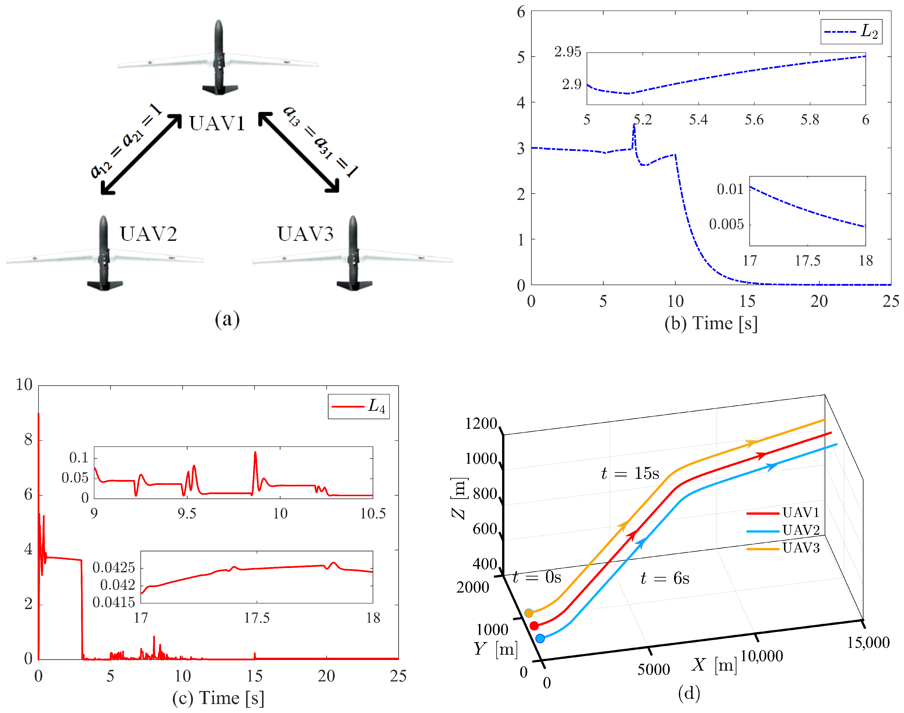
To validate the effectiveness and superiority of the proposed control algorithm in achieving predefined convergence time and conserving communication resources, a formation system consisting of three fixed-wing UAVs is established in this section. The corresponding communication topology is illustrated in Figure 1a, and its Laplacian matrix is given as follows
L = 2 1 1 1 1 0 1 0 1
To achieve prescribed-time control of the UAV formation, the following prescribed-time performance functions are selected for the velocity and attitude layers
η V i ( t ) = ( η V i 0 η V i ) exp t T V f t + η V i , t [ 0 , T V f ) s η V i , t [ T V f , + ) s
η φ i ( t ) = ( η φ i 0 η φ i ) exp t T φ f t + η φ i , t [ 0 , T φ f ) s η φ i , t [ T φ f , + ) s
where T V f = 7 , η V i 0 = 10 , η V i = 1 , T φ f = 5 s, η φ i 0 = 10 , η φ i = 1 .
The initial velocity states of the multi-UAV formation are selected as V 1 = 40 m m s s , V 2 = 42 m m s s , and V 3 = 38 m m s s . The initial attitude angles are chosen as φ 1 = [ 0.5 , 0 , 0.5 ] T deg , φ 2 = [ 0 , 0.8 , 0 ] T deg , φ 1 = [ 1 , 0.4 , 0 ] T deg , and the initial angular rates are set to ω 1 = ω 2 = ω 3 = [ 0 , 0 , 0 ] T deg / s . UAV 2 is subjected to an external disturbance d ω i = [ 0.1 cos ( 3 t ) , 0.2 cos ( t ) , 0.4 cos ( 5 t ) ] within t [ 18 , 20 ] s. Additional detailed system parameters of the UAVs are provided in Table 1 [37].
It is assumed that the multi-UAV formation system is executing a coordinated turn-and-climb mission, requiring both velocity and attitude to rapidly adjust to desired values within a prescribed time and continuously adapt to updated commands. The desired velocity and attitude commands are defined as
V r = 45 m / s , 0 s t 7 s 50 5 e 2 t 7 m / s , 7 s < t 17 s 55 5 e 2 ( t 17 ) m / s , 17 s < t 25 s φ r = [ 4 deg , 5 deg , 5 deg ] T , 0 s t 6 s [ 4 e ( t 6 ) deg , 5 deg , 5 deg ] T , 6 s < t 15 s [ 4 e ( t 6 ) deg , 5 e ( t 15 ) deg , 5 deg ] T , 15 s < t 25 s
Furthermore, the key parameters of the proposed DSTM and controller are selected as follows: For the velocity layer, we have λ V 1 = λ V 2 = λ V 3 = 10 , k V 1 = k V 2 = k V 3 = 20 , l V 11 = l V 21 = l V 31 = 1 , l V 12 = l V 22 = l V 32 = 1 , p V 11 = p V 12 = p V 13 = 0.5 , p V 21 = p V 22 = p V 23 = 0.5 , q V 11 = q V 12 = q V 13 = 20 , q V 21 = q V 22 = q V 23 = 20 , C V 11 = C V 21 = C V 31 = 3 , C V 12 = C V 22 = C V 32 = 0.3 , T V f = 7 s, T V s = 5 s, c 1 = c 2 = 5 . Additionally, for i = 1 , 2 , 3 , we have o V i = 5 , σ V i 1 = 0.001 , σ V i 2 = σ V i 3 = σ V i 4 = 1 , V i = 1 . Then for the attitude layer, we have λ ω i = diag { 20 , 20 , 20 } , K φ 2 = diag { 20 , 20 , 20 } , l ω 11 = l ω 21 = l ω 31 = 1 , l ω 12 = l ω 22 = l ω 32 = 1 . For m = { ϕ , θ , ψ } , we have p m 11 = p m 12 = p m 13 = 0.5 , p m 21 = p m 22 = p m 23 = 0.5 , q m 11 = q m 12 = q m 13 = 12 , q m 21 = q m 22 = q m 23 = 12 , C m 11 = C m 21 = C m 31 = 5 , C m 12 = C m 22 = C m 32 = 0.9 , T m f = 5 s, T m s = 3 s, c 3 = 10 , c 4 = 1 . Additionally, for i = 1 , 2 , 3 , l = 1 , 2 , 3 , we have o ω i = 1 , σ ω i l 1 = 0.001 , σ ω i l 2 = σ ω i l 3 = σ ω i l 4 = 1 , ω i = 1 .
Figure 4b shows the Lyapunov function corresponding to the attitude layer. The plot indicates that the designed Lyapunov function converges asymptotically to zero. Minor fluctuations are observed during the convergence process due to the dynamic self-triggering mechanism, yet an overall converging trend is maintained, demonstrating that the designed dynamic self-triggering mechanism and control law ensure asymptotic stability of the attitude layer. Figure 4d presents the Lyapunov function for the velocity layer, which also converges asymptotically to near zero within a finite time, confirming the asymptotic stability achieved by the proposed dynamic self-triggering mechanism and thrust control law. Figure 4d illustrates the flight trajectory of the UAV formation during the mission, showing that the formation successfully maintains its configuration and adjusts to the desired attitude throughout the flight, further validating the effectiveness of the proposed dynamic self-triggering mechanism and control laws.
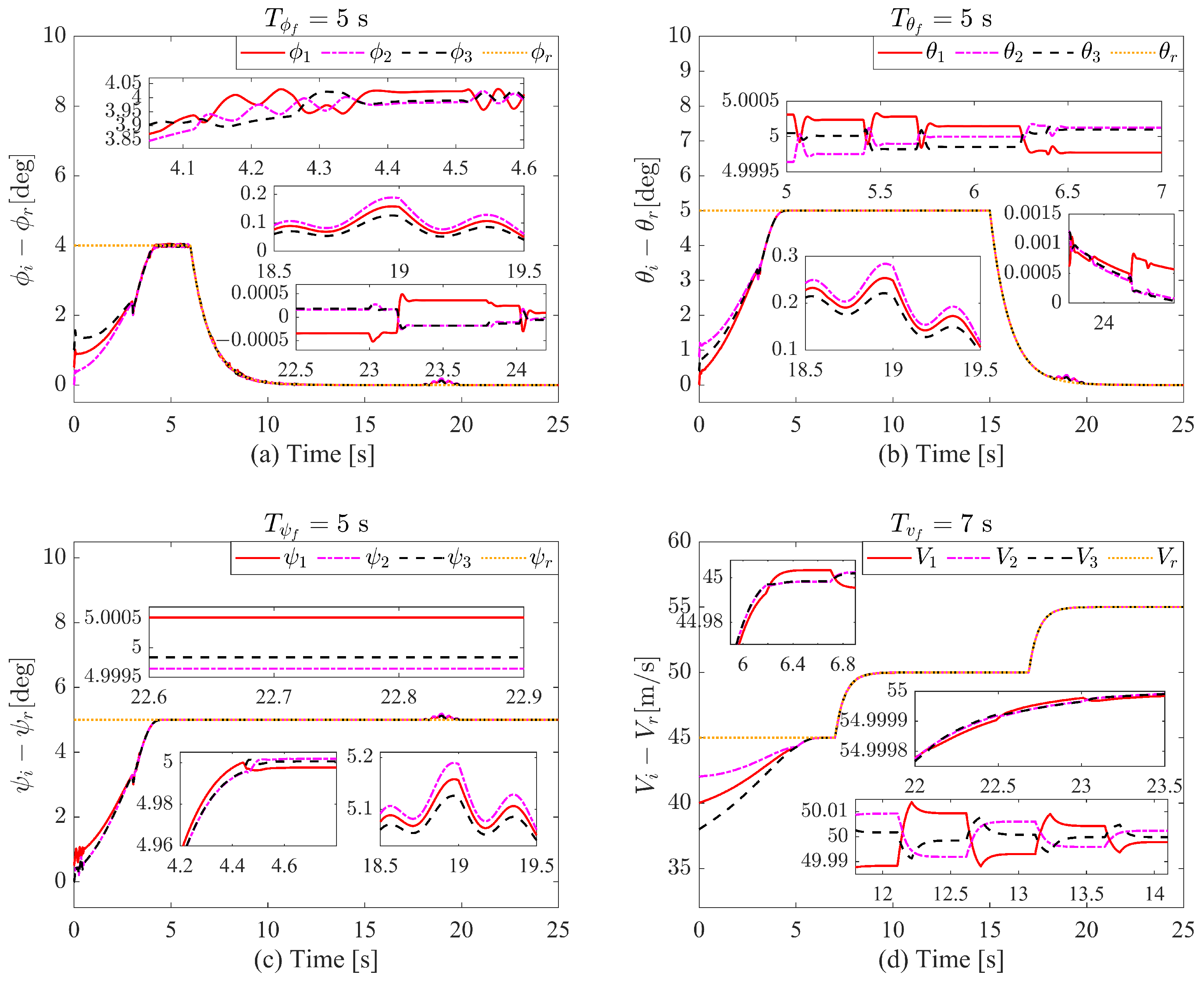
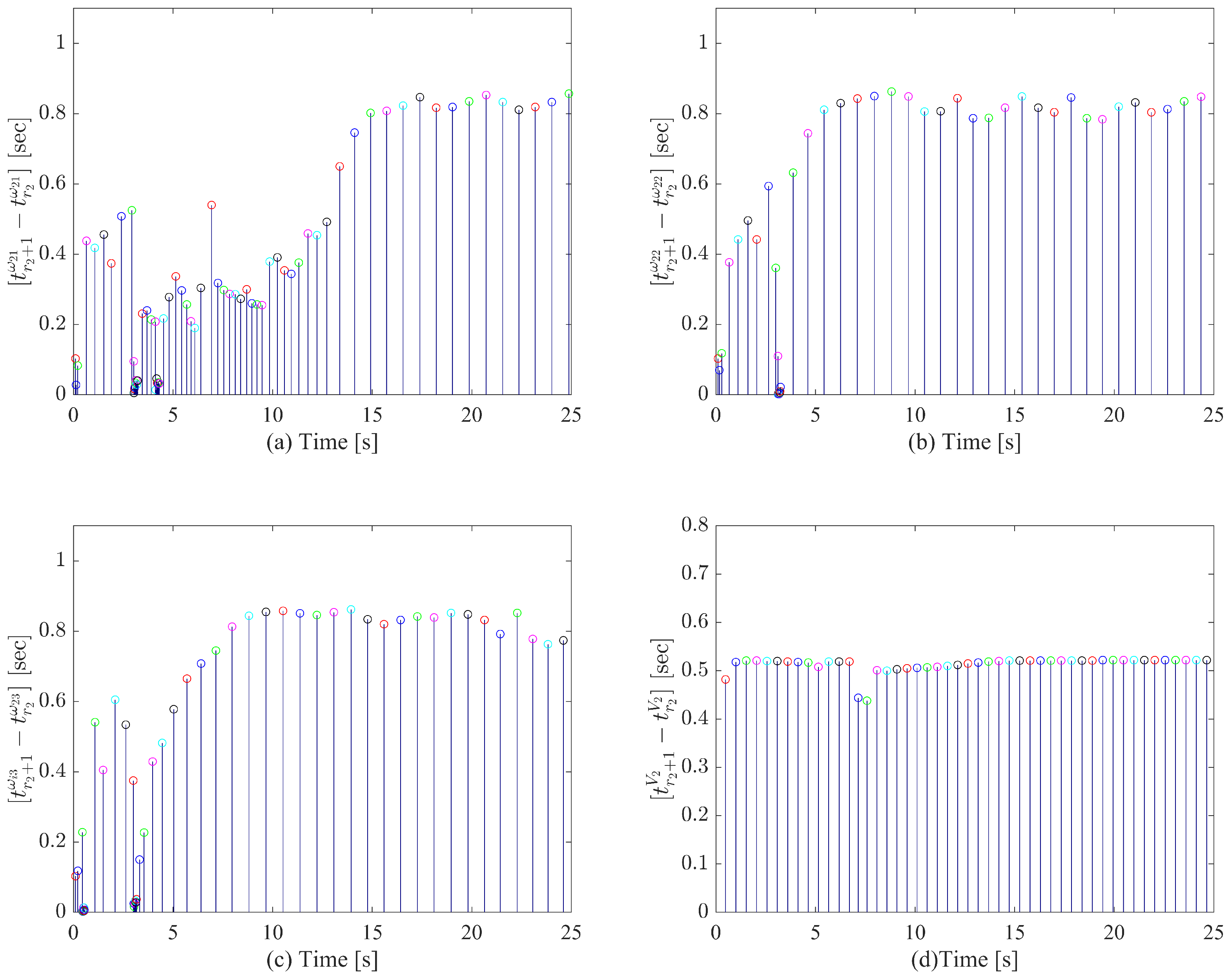
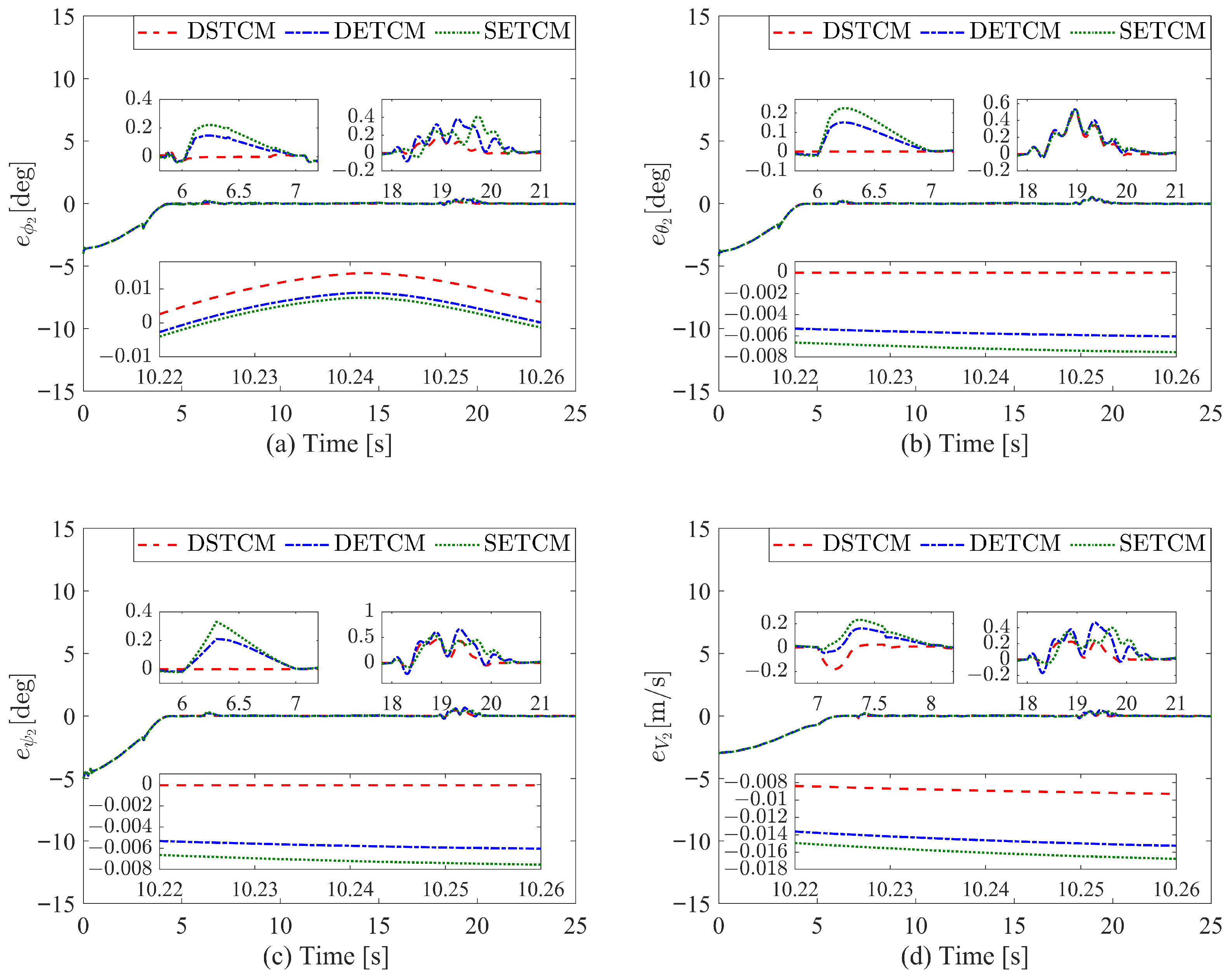
Figure 5a–d present the tracking response curves of each UAV for the desired attitude angles and velocity. The attitude command tracking processes in Figure 5a–c demonstrate rapid tracking of the initial step attitude commands within the prescribed convergence time T φ f = 5 s, and successful subsequent tracking of time-varying attitude commands. Similarly, the velocity command tracking process in Figure 5d achieves fast convergence for the initial step velocity command within T V f = 7 s and maintains accurate tracking of the desired velocity profile.
Figure 5a–d illustrate the tracking performance of each UAV with respect to desired attitude angles and velocity. As observed in Figure 5a–c, the attitude command tracking exhibits a rapid and precise response to the initial step commands, achieving convergence strictly within the prescribed time frame of T φ f = 5 s . Furthermore, the controllers demonstrate robust tracking capability in following time-varying attitude commands throughout the operation. Similarly, as shown in Figure 5d, the velocity command tracking not only attains fast convergence for the initial step command within T V f = 7 s , but also consistently maintains accurate tracking of the time-evolving velocity profile, highlighting the effectiveness of the proposed control architecture under dynamic conditions.
Figure 6a–d depict the transformed error trajectories for each UAV, where the blue curves indicate the designed self-adjusting performance boundaries. The transformed errors in the attitude layer, presented in Figure 6a–c, confirm that all errors converge to zero within the predefined time T φ f = 5 s . Notably, under the action of the adaptive update law (11) for the attitude layer, the performance bounds dynamically expand in response to external disturbances occurring during the interval t [ 18 , 20 ] s , thereby preventing constraint violations despite transient error increases. Once the disturbances subside, the transformed errors rapidly return to zero, demonstrating both resilience and adaptability. In a similar manner, the velocity layer transformed error in Figure 6d guarantees convergence within T V f = 7 s . The self-adjusting performance mechanism successfully enforces full-state constraints across all UAVs, while the implementation of single-sided constraints markedly attenuates oscillatory behavior—commonly encountered in conventional double-sided constraint designs—thus significantly enhancing transient performance and dynamic responsiveness. Additionally, the initial error transformation process for UAV2, illustrated in Figure 7a–d, verifies that the proposed method effectively circumvents the initial value problem associated with state constraints, underscoring its general applicability. Collectively, the results from Figure 2, Figure 3 and Figure 4 substantiate that the prescribed-time control strategy facilitates swift and stable reconfiguration of the UAV formation state, effectively addressing stringent timing requirements essential for practical mission scenarios.
To further validate the efficacy of the proposed DSTM, Figure 8 illustrates the event-triggering instants corresponding to the angular rate error and the velocity transformed error for UAV2 under DSTM. As shown in Figure 8a–c, the angular rate error triggers events frequently within short time intervals during both the initial transient phase and periods of command variation. This high-frequency triggering ensures a rapid system response, enabling the attitude control loop to closely and promptly track desired command changes. In contrast, during steady-state operation, the triggering frequency is significantly reduced, thereby avoiding unnecessary communication and computation while still maintaining satisfactory inter-event time intervals. Further analysis of the triggering intervals for angular rate errors in Figure 9a–c reveals that the DSTM proactively adjusts the triggering behavior according to system states. In this figure, adjacent triggering intervals are distinguished by different colors for clear visualization. The mechanism predicts and imposes shorter intervals during dynamically critical phases to prioritize control performance and mission execution, while adopting longer intervals during steady operation to conserve communication bandwidth and computational resources. Meanwhile, as observed in Figure 8d and Figure 9d, the triggering pattern for the velocity-transformed tracking error remains consistently stable across different operational phases, reflecting the adaptability and robustness of the triggering strategy for slower-varying states. Overall, these results corroborate the effectiveness of the proposed DSTM in balancing control performance and resource efficiency, while also confirming the elimination of Zeno behavior, thereby ensuring practical implementability of the event-triggered framework.
For further comparison of the superiority of the proposed method, Figure 10 provides the error response curves of UAV2 under different event-triggering mechanisms. Compared with DETCM [43] and SETCM [44], DSTCM exhibits smaller steady-state errors, faster response speed during command changes, and slightly better disturbance rejection. To quantitatively evaluate the steady-state and transient performance of DSTCM, key performance indicators are selected in Table 2: Integral of Squared Error (ISE), Integral of Time-weighted Squared Error (ITSE), Integral of Absolute Error (IAE), Integral of Time-weighted Absolute Error (ITAE), Maximum Absolute Error ( M p ), and Settling Time ( T s ) within a 2% error band. Across all error states (V, ϕ , θ , ψ ), DSTM shows significant advantages in multiple key metrics. Specifically, in time-weighted metrics reflecting system response speed, DSTM performs notably well: for velocity state V, its ITSE value is 37.4350, significantly lower than DTM’s 39.3849 and STM’s 39.1370; for yaw angle ψ , its ITAE value is 24.2927, markedly better than DTM’s 35.2379 and STM’s 36.1594. These results fully demonstrate that DSTM effectively accelerates the convergence process and reduces time-accumulated errors during transients, indicating clear superiority in response speed.
In terms of control accuracy, DSTCM also exhibits excellent performance. From the IAE metric, DSTCM achieves the smallest values across all states. For instance, in the pitch angle θ state, the IAE value is 10.3685, while DETCM and SETCM yield 10.8179 and 10.9284, respectively. This indicates that DSTCM not only responds rapidly but also effectively suppresses error accumulation, maintaining higher control precision throughout operation. It is particularly noteworthy that DSTCM achieves better accuracy while maintaining the same level of maximum overshoot ( M p ) as other mechanisms, reflecting its comprehensive control performance. Through a comprehensive comparison of various performance metrics, it is evident that DSTCM achieves an optimal balance across multiple dimensions of the control system. Although SETCM shows a slight advantage in the ISE metric, which only reflects error control at certain instants, DSTCM achieves optimal results in time-weighted metrics (ITSE, ITAE) and absolute error metrics (IAE), which better represent overall system performance. This comprehensive advantage stems from the unique design concept of DSTCM: its dynamic self-triggering characteristics avoid the resource waste associated with continuous monitoring while ensuring improved control performance through intelligent adjustment of triggering thresholds.
Table 3 demonstrates that the proposed dynamic self-triggering communication mechanism (DSTCM) exhibits significant advantages in communication efficiency. Compared to traditional event-triggering mechanisms, DSTCM substantially reduces the communication monitoring frequency, alleviates network communication burden, and effectively extends the triggering intervals, greatly enhancing the real-time communication performance of multi-UAV systems. In terms of control performance, the mechanism maintains excellent control accuracy while achieving high communication efficiency. Experimental results show that despite a significant reduction in communication instances, the control performance of the system is not noticeably affected, and the control accuracy across all channels remains consistent with traditional methods. This optimized design, which trades minimal control performance degradation for substantial communication efficiency improvement, fully proves the practical value and superiority of the mechanism in engineering applications. It provides an effective technical solution for cooperative control of multi-UAV systems in resource-constrained environments, demonstrating promising prospects for practical application.
Experiments were conducted on a hardware-in-the-loop(HIL) simulation platform to verify the feasibility of the proposed control strategy under realistic simulation conditions. As shown in Figure 11, Figure 11a illustrates the hardware and software architecture of the platform, while Figure 11b presents a photograph of the actual HIL simulation platform. The platform adopts a master-slave architecture: the monitoring computer develops the control system and implements algorithms through an integrated development environment; the real-time simulator operates the six-degree-of-freedom dynamics model of the fixed-wing UAV, exchanging data with the flight controller via an RS232 serial interface; the monitoring computer, assisted by professional visualization software, displays and analyzes the UAV formation flight status in real-time, together forming a complete closed-loop validation system. Figure 12 presents the real-time flight trajectories obtained at two critical mission stages, specifically at 17 s (mid-mission) and 22 s (mission completion). The red arrows in the Figure 4 denote the flight direction of the UAV formation.The experimental results indicate that the controller effectively maintains formation stability and trajectory tracking performance throughout the collaborative mission. Furthermore, the flight trajectories observed in the HIL tests closely match the results shown in Figure 4d, and the UAV formation consistently maintains a stable configuration throughout the flight. The consistency between the HIL simulation and the numerical simulation results further validates the effectiveness and engineering applicability of the proposed control method.

5. Conclusions

This study addresses the prescribed-time cooperative formation control problem for multiple 6-DOF fixed-wing UAVs under limited communication resources and strict time constraints. A novel control framework is proposed that integrates a Dynamic Self-Triggered Communication Mechanism (DSTCM) with a prescribed-time control strategy. The DSTCM effectively reduces communication frequency and eliminates the need for continuous state monitoring, thereby conserving both communication and computational resources. Meanwhile, a time-varying unilateral constrained performance function is introduced to ensure that the formation tracking error converges to a predefined residual set within a user-specified time, independent of initial conditions and under full-state constraints.
It is noteworthy, however, that the current theoretical guarantees are established under ideal communication conditions, specifically relying on a persistently connected network (Assumption 1) and the constant availability of a command-informing leader (Assumption 2). Acknowledging that these assumptions may be challenged in real-world operations due to signal obstructions, dynamic obstacles, or node failures is a crucial step toward practical deployment. Therefore, future work will be directed at enhancing the system’s resilience. This includes extending the proposed framework to handle more complex and adverse scenarios, such as maintaining cooperation in intermittently connected networks; developing fault-tolerant mechanisms for leader failure or command loss; operating in three-dimensional obstacle-rich environments [45]; and explicitly accounting for heterogeneous UAV formations [46] and real-world communication imperfections like delays and packet losses. The integration of learning-based methods to further enhance the adaptability and robustness of the DSTCM in these non-ideal contexts also presents a promising research direction.

Author Contributions

Conceptualization, J.L.; methodology, J.L. and Z.Y.; software, J.L. and Z.Y.; validation, Z.Y. and N.W.; formal analysis, Z.Y.; investigation, N.W.; resources, N.W.; data curation, Z.Y.; writing—original draft preparation, J.L.; writing—review and editing, Z.Y. and N.W.; visualization, J.L.; supervision, N.W.; project administration, J.L. All authors have read and agreed to the published version of the manuscript.

Funding

This work is supported by the Shandong Provincial Natural Science Foundation under grant ZR2025MS03, the National Natural Science Foundation of China under grant 62403486, the Postdoctoral Fellowship Program of CPSF under grant GZB20230988, and the Postdoctoral Science Foundation General Program under grant 2024M754258.

Data Availability Statement

The original contributions presented in the study are included in the article, further inquiries can be directed to the corresponding author.

Conflicts of Interest

The authors declare no conflicts of interest.

References

  1. Wu, Z.; Xie, Q.; Wang, Z.; Huang, X.; Peng, C.; Wu, Y. Terrain-aware UAV-enabled mobile edge computing in urban environments: A constrained multi-objective approach with task-adaptive mechanism. IEEE Trans. Veh. Technol. 2025. [Google Scholar] [CrossRef]
  2. Liu, X.; Durrani, T.S. Joint multi-UAV deployments for air–ground integrated networks. IEEE Aerosp. Electron. Syst. Mag. 2022, 37, 4–12. [Google Scholar] [CrossRef]
  3. Zhao, J.; Wen, Z.; Mohanta, K.; Subasu, S.; Fremond, R.; Su, Y.; Kallaka, R.; Tsourdos, A. UAV operations and vertiport capacity evaluation with a mixed-reality digital twin for future urban air mobility viability. Drones 2025, 9, 621. [Google Scholar] [CrossRef]
  4. Liu, Q.; Tian, B.; Zhang, X.; Lu, J.; Li, Z. Sampling-based hierarchical trajectory planning for formation flight. IEEE Trans. Intell. Transp. Syst. 2025. [Google Scholar] [CrossRef]
  5. Qin, Y.; Wang, Z.; Zhang, H. Joint task allocation and power optimization in multi-UAV systems: An overlapping coalition formation game approach. IEEE Trans. Veh. Technol. 2025. [Google Scholar] [CrossRef]
  6. Yan, Y.; Liu, S.; Hao, R. RRT*-APF path planning and MA-AADRC-SMC control for cooperative 3-D obstacle avoidance in multi-UAV formations. Drones 2025, 9, 611. [Google Scholar] [CrossRef]
  7. Hu, W.; Zhang, Y.; Li, J.; Wang, Y.; Li, Y.; Liu, M. TD3 agent-based nonlinear dynamic inverse control for fixed-wing UAV attitudes. IEEE Trans. Intell. Transp. Syst. 2025. [Google Scholar] [CrossRef]
  8. Su, Z.; Fan, J.; Li, C.; Huang, Y.; Jiang, C. Coordinated trajectory and attitude control for fixed-wing UAV shipboard SideArm recovery with safety constraints. IEEE Trans. Aerosp. Electron. Syst. 2025. [Google Scholar] [CrossRef]
  9. Freitas, A.; Rabbath, C.A.; Williams, C.; Lechevin, N.; Givigi, S. Multi-unmanned aerial vehicles cooperative tactics: A survey. IEEE Access 2025, 13, 119897–119921. [Google Scholar] [CrossRef]
  10. Liu, S.; Lin, Z.; Huang, W.; Yan, B. Technical development and future prospects of cooperative terminal guidance based on knowledge graph analysis: A review. J. Zhejiang Univ. Sci. A 2025, 26, 605–634. [Google Scholar] [CrossRef]
  11. Zhang, R.; Chen, X.; Li, M. Multi-UAV cooperative task assignment based on multi-strategy improved DBO. Cluster Comput. 2025, 28, 195. [Google Scholar] [CrossRef]
  12. Guan, X.; Yiu, K.-F.C.; Li, B.; Zeng, Y.; Zhang, R. 3D trajectory optimization for fixed-wing UAV communications with full UAV dynamics. IEEE Trans. Veh. Technol. 2025. [Google Scholar] [CrossRef]
  13. Hu, S.; Yuan, X.; Ni, W.; Wang, X.; Jamalipour, A. Visual camouflage and online trajectory planning for unmanned aerial vehicle-based disguised video surveillance: Recent advances and a case study. IEEE Veh. Technol. Mag. 2023, 18, 48–57. [Google Scholar] [CrossRef]
  14. Cara, A.B.; Wagner, C.; Hagras, H.; Pomares, H.; Rojas, I. Multiobjective optimization and comparison of nonsingleton type-1 and singleton interval type-2 fuzzy logic systems. IEEE Trans. Fuzzy Syst. 2013, 21, 459–476. [Google Scholar] [CrossRef]
  15. Juang, C.-F.; Hsu, C.-H. Reinforcement interval type-2 fuzzy controller design by online rule generation and Q-value-aided ant colony optimization. IEEE Trans. Syst. Man Cybern. Part B 2009, 39, 1528–1542. [Google Scholar] [CrossRef]
  16. Boran, F.E.; Akay, D. A generic method for the evaluation of interval type-2 fuzzy linguistic summaries. IEEE Trans. Cybern. 2014, 44, 1632–1645. [Google Scholar] [CrossRef]
  17. Tang, M.; Feng, C.; Quek, T.Q.S. Decentralized semantic communication and cooperative tracking control for a UAV swarm over wireless MIMO fading channels. IEEE Trans. Veh. Technol. 2025. [Google Scholar] [CrossRef]
  18. Bai, Y.; Zhang, Y. Dynamic offloading based on Lyapunov optimization for UAV-assisted maritime IoT-MEC networks. IEEE Trans. Veh. Technol. 2025. [Google Scholar] [CrossRef]
  19. Ding, T.; Li, Y.; Wang, Z.; Wang, J.; Wang, F. Disturbance-resilient UAV formation control for low-altitude economy: Elliptical configuration tracking via a generalized predefined-time approach. IEEE Trans. Veh. Technol. 2025. [Google Scholar] [CrossRef]
  20. Han, C.; Li, W.; Shi, M.; Li, M.; Lin, B.; Qin, K. Human-in-the-loop prescribed performance distributed formation tracking control of networked quadrotor UAVs. IEEE Trans. Veh. Technol. 2025. [Google Scholar] [CrossRef]
  21. Zhao, S.; Ni, J.; Lei, T.; Du, Y.; Deng, S. Dynamic-memory event-triggered fixed-time distributed power management for UAV power system under intermittent communication failures. IEEE Trans. Aerosp. Electron. Syst. 2025. [Google Scholar] [CrossRef]
  22. Su, M.; Chai, H.; Zhao, C.; Lyu, Y.; Hu, J. Lightweight obstacle avoidance for fixed-wing UAVs using entropy-aware PPO. Drones 2025, 9, 598. [Google Scholar] [CrossRef]
  23. Zhao, S.; Zheng, J.; Zuo, Z.; Wang, X. Prescribed-time elliptical circumnavigation for multiple moving targets by multi-UAVs. IEEE Trans. Intell. Veh. 2024. [Google Scholar] [CrossRef]
  24. Kong, L.; Reis, J.; He, W.; Silvestre, C. Event-triggered prescribed-time tracking control for UAVs using polynomial error trajectories. IEEE Trans. Autom. Sci. Eng. 2025, 22, 16476–16486. [Google Scholar] [CrossRef]
  25. Shi, Y.; Li, J.; Lv, M.; Wang, N.; Yuan, Y.; Chang, J. Synergistic constrained control of 6-DOF fixed-wing multi-UAVs with dynamic self-triggered communication. IEEE Trans. Autom. Sci. Eng. 2025, 22, 14818–14832. [Google Scholar] [CrossRef]
  26. Hashim, H.A.; Brown, L.J.; McIsaac, K. Nonlinear pose filters on the special Euclidean group SE(3) with guaranteed transient and steady-state performance. IEEE Trans. Syst. Man Cybern. Syst. 2021, 51, 2949–2962. [Google Scholar] [CrossRef]
  27. Shu, L.; Xu, S. Prescribed-time optimal formation control using fuzzy reinforcement learning for second-order multiagent systems. IEEE Trans. Cybern. 2025. [Google Scholar] [CrossRef]
  28. Chen, J.; Yue, D.; Dou, C.; Weng, S.; Xie, X.; Li, Y.; Hancke, G.P. Static and dynamic event-triggered mechanisms for distributed secondary control of inverters in low-voltage islanded microgrids. IEEE Trans. Cybern. 2020, 52, 6925–6938. [Google Scholar] [CrossRef]
  29. He, W.; Mo, Z. Secure event-triggered consensus control of linear multiagent systems subject to sequential scaling attacks. IEEE Trans. Cybern. 2022, 52, 10314–10327. [Google Scholar] [CrossRef]
  30. Wu, Y.; Zhang, H.; Wang, Z.; Huang, C. Distributed event-triggered consensus of general linear multiagent systems under directed graphs. IEEE Trans. Cybern. 2022, 52, 608–619. [Google Scholar] [CrossRef] [PubMed]
  31. Wei, L.; Chen, M.; Shi, S. Dynamic event-triggered consensus cost-based switching control for UAV formation with disturbances. IEEE Trans. Intell. Veh. 2024, 9, 3531–3543. [Google Scholar] [CrossRef]
  32. Tang, H.; Chen, Y. Dynamic event-triggered distributed MPC for heterogeneous UAVs–UGVs against DoS attacks. IEEE Trans. Aerosp. Electron. Syst. 2024, 60, 7931–7944. [Google Scholar] [CrossRef]
  33. Gai, W.; Li, S.; Zhang, J.; Zheng, Y.; Zhong, M. Dynamic event-triggered Hι/H optimization approach to fault detection for unmanned aerial vehicles. IEEE Trans. Instrum. Meas. 2022, 71, 3512211. [Google Scholar] [CrossRef]
  34. Cao, Z.; Wang, S.; Ge, X.; Peng, C.; Zhao, H. A distributed self-triggered control scheme for multi-unmanned aerial vehicle containment control under Markov switching topologies and channel fading. IEEE Trans. Autom. Sci. Eng. 2025, 22, 19775–19788. [Google Scholar] [CrossRef]
  35. Xiao, H.; Yang, Y.; Yu, D.; Lai, G.; Chen, C.L.P. 3D self-triggered-organized communication topology based UAV swarm consensus system with distributed extended state observer. IEEE Trans. Netw. Sci. Eng. 2025, 12, 3985–4000. [Google Scholar] [CrossRef]
  36. Jin, Z.; Bai, L.; Wang, Z.; Zhang, P. Self-triggered distributed formation control of fixed-wing unmanned aerial vehicles subject to velocity and overload constraints. IEEE Trans. Autom. Sci. Eng. 2024, 21, 4082–4093. [Google Scholar] [CrossRef]
  37. Oland, E. Nonlinear Control of Fixed-Wing Unmanned Aerial Vehicles. Ph.D. Thesis, Norwegian University of Science and Technology, Trondheim, Norway, 2014. [Google Scholar]
  38. Qu, F.; Tong, S. Observer-based fuzzy adaptive quantized control for uncertain nonlinear multiagent systems. Int. J. Adapt. Control Signal Process. 2019, 33, 567–585. [Google Scholar] [CrossRef]
  39. Hagras, H.A. A hierarchical type-2 fuzzy logic control architecture for autonomous mobile robots. IEEE Trans. Fuzzy Syst. 2004, 12, 524–539. [Google Scholar] [CrossRef]
  40. Cheng, W.; Zhang, K.; Jiang, B. Fixed-time and prescribed-time fault-tolerant optimal tracking control for heterogeneous multiagent systems. IEEE Trans. Autom. Sci. Eng. 2024, 21, 7275–7286. [Google Scholar] [CrossRef]
  41. Meng, K.; He, X.; Wu, Q.; Li, D. Multi-UAV collaborative sensing and communication: Joint task allocation and power optimization. IEEE Trans. Wirel. Commun. 2023, 22, 4232–4246. [Google Scholar] [CrossRef]
  42. Castaneda, H.; Salas-Pena, O.S.; Leon-Morales, J. Extended observer based on adaptive second order sliding mode control for a fixed wing unmanned aerial vehicle. ISA Trans. 2017, 66, 226–232. [Google Scholar] [CrossRef] [PubMed]
  43. Huang, Y.; Xu, X.; Meng, Z.; Sun, J. A smooth distributed formation control method for quadrotor UAVs under event-triggering mechanism and switching topologies. IEEE Trans. Veh. Technol. 2025, 74, 10081–10091. [Google Scholar] [CrossRef]
  44. Li, Y.-X.; Yang, G.-H. Adaptive neural control of pure-feedback nonlinear systems with event-triggered communications. IEEE Trans. Neural Netw. Learn. Syst. 2018, 29, 6242–6251. [Google Scholar] [CrossRef]
  45. Tian, L.; Wang, X.; Chen, H. Heterogeneous formation tracking for fixed-wing UAVs and nonholonomic UGVs with different asymmetric constraints. IEEE Trans. Veh. Technol. 2025. [Google Scholar] [CrossRef]
  46. Zhang, K.; Si, D.; Wang, W.; Cao, J.; Zhang, Y. Transfer learning for distributed intelligence in aerial edge networks. IEEE Wirel. Commun. 2021, 28, 74–81. [Google Scholar] [CrossRef]
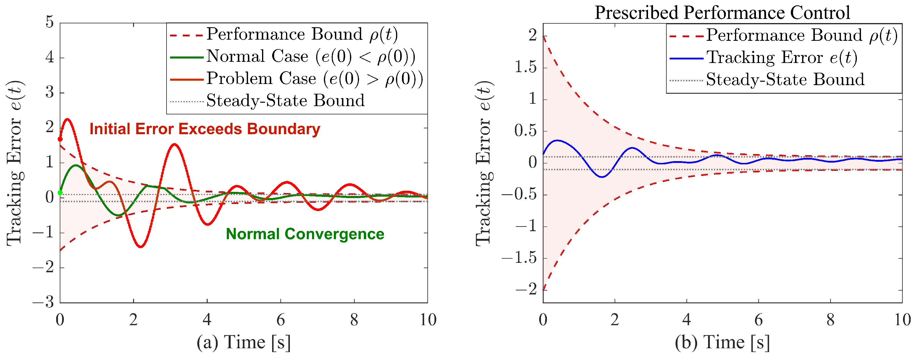
Figure 1. (a) Initial value problem of prescribed performance control method; (b) double-sided constraints of the prescribed performance function.
Drones 09 00715 g001
Figure 3. Time response of different PTPFs. (a) T f = 4 s; (b) T f = 6 s; (c) T f = 8 s.
Drones 09 00715 g003
Figure 4. (a) Communication topology; (b) the curve of Lyapunov function L 2 ; (c) the curve of Lyapunov function L 4 ; (d) multi-UAV trajectory.
Drones 09 00715 g004
Figure 5. Multi-UAV state trajectories. (a) Roll angle trajectories; (b) pitch angle trajectories; (c) yaw angle trajectories; (d) speed trajectories.
Drones 09 00715 g005
Figure 6. Multi-UAV transformation tracking error trajectories. (a) Roll angle tracking error trajectories; (b) pitch angle tracking error trajectories; (c) yaw angle tracking error trajectories; (d) speed tracking error trajectories.
Drones 09 00715 g006
Figure 7. The tracking error of UAV 2 and the related transformation error. (a) Roll angle tracking error trajectories; (b) pitch angle tracking error trajectories; (c) yaw angle tracking error trajectories; (d) speed tracking error trajectories.
Drones 09 00715 g007
Figure 8. Multi-UAV triggered moments. (a) Roll angle triggered moments; (b) pitch angle triggered moments; (c) yaw angle triggered moments; (d) speed triggered moments.
Drones 09 00715 g008
Figure 9. Multi-UAV triggered interval. (a) Roll angle triggered interval; (b) pitch angle triggered interval; (c) yaw angle triggered interval; (d) speed triggered interval.
Drones 09 00715 g009
Figure 10. Comparison of state errors under different communication mechanisms. (a) Roll angle trajectories; (b) pitch angle trajectories; (c) yaw angle trajectories; (d) speed trajectories.
Drones 09 00715 g010
Figure 11. (a) Software hardware architecture; (b) hardware-in-the-loop simulation platform.
Drones 09 00715 g011
Figure 12. The real-time flight trajectories. (a) The flight mission in process (t = 17 s); (b) complete the flight mission (t = 22 s).
Drones 09 00715 g012
Table 1. UAV structure and aerodynamic parameters.
ParameterValue/UnitParameterValue/UnitParameterValue/Unit
m i 20.64/kg C L 0 i 0.1 (constant) C n 0 i 0.022 (constant)
B i 1.96/m C L α i 0.25/ rad 1 C n β i 0.036/ rad 1
S i 1.37/ m 2 C D 0 i 0.5 (constant) C n p i −0.151/ rad 1 · s
C ¯ i 0.76/m C Y β i −0.1/ rad 1 C n r i −0.195/ rad 1 · s
ρ 1.29/ kg · m 3 C l 0 i −0.001 (constant) C n δ a i −0.036/ rad 1
g9.8/ m · s 2 C l β i −0.038 (constant) C n δ r i −0.055/ rad 1
L x z i 0.59/ kg · m 2 C l p i −0.213/ rad 1 · s C m 0 i 0.022 (constant)
C l r i 0.114/ rad 1 · s C l δ a i −0.056/ rad 1 C m α i −0.473/ rad 1
C l δ r i 0.014/ rad 1 C m q i −3.449/ rad 1 · s C m δ e i -0.364/ rad 1 · s
Table 2. Comparison of Steady-State and Transient Performance Under Different Event-Triggered Mechanisms.
ControllerStateISEITSEIAEITAEMpTs(s)
designed DSTCM V 2 22.746137.435010.539526.04623.000029.953
DETCM in [43] V 2 22.712739.384911.086136.25323.000029.956
SETCM in [44] V 2 22.671539.137011.161837.30863.000029.956
designed DSTCM e ϕ 2 26.847933.88259.787018.06624.000030.000
DETCM in [43] e ϕ 2 26.727335.232010.367428.48864.000029.956
SETCM in [44] e ϕ 2 26.690635.328710.466529.90114.000029.956
designed DSTCM e θ 2 29.797938.626410.368522.25814.200030.000
DETCM in [43] e θ 2 29.613838.952310.817929.51934.200029.956
SETCM in [44] e θ 2 29.565738.860910.928431.03354.200029.956
designed DSTCM e ψ 2 39.128547.583311.689524.29275.000030.000
DETCM in [43] e ψ 2 39.040550.256112.346635.23795.000029.956
SETCM in [44] e ψ 2 38.947049.409112.421636.15945.000029.956
Table 3. Communication efficiency and control performance comparison.
Performance MetricAlgorithmVelocityRollPitchYaw
Monitoring Timesdesigned DSTCM59767773
Monitoring TimesDETCM in [43]5000500050005000
Monitoring TimesSETCM in [44]5000500050005000
Reduction Rate (%)designed DSTCM98.8298.4898.4698.54
Avg. Interval (s)designed DSTCM0.4240.3290.3250.342
Avg. Interval (s)DETCM in [43]0.0050.0050.0050.005
Avg. Interval (s)SETCM in [44]0.0050.0050.0050.005
RMSEdesigned DSTCM0.87080.94610.99681.1422
RMSEDETCM in [43]0.87020.94400.99371.1409
RMSESETCM in [44]0.86940.94340.99291.1396
Disclaimer/Publisher’s Note: The statements, opinions and data contained in all publications are solely those of the individual author(s) and contributor(s) and not of MDPI and/or the editor(s). MDPI and/or the editor(s) disclaim responsibility for any injury to people or property resulting from any ideas, methods, instructions or products referred to in the content.