Article

Autonomous Navigation of Unmanned Ground Vehicles Based on Micro-Shell Resonator Gyroscope Rotary INS Aided by LDV

College of Intelligence Science and Technology, National University of Defense Technology, Changsha 410073, China
*
Author to whom correspondence should be addressed.
Drones 2025, 9(10), 706; https://doi.org/10.3390/drones9100706 (registering DOI)
Submission received: 31 August 2025 / Revised: 9 October 2025 / Accepted: 11 October 2025 / Published: 13 October 2025

Abstract

Micro-Shell Resonator Gyroscopes have obvious SWaP (Size, Weight and Power) advantages and applicable accuracy for the autonomous navigation of Unmanned Ground Vehicles (UGVs), especially under GNSS-denied environments. When the Micro-Shell Resonator Gyroscope Rotary Inertial Navigation System (MSRG–RINS) operates in the whole-angle mode, its bias varies as an even-harmonic function of the pattern angle, which leads to difficulty in estimating and compensating the bias based on the MSRG in the process of attitude measurement. In this paper, an attitude measurement method based on virtual rotation self-calibration and rotary modulation is proposed for the MSRG–RINS to address this problem. The method utilizes the characteristics of the two operating modes of the MSRG, the force-rebalanced mode and whole-angle mode, to perform virtual rotation self-calibration, thereby eliminating the characteristic bias of the MSRG. In addition, the reciprocating rotary modulation method is used to suppress the residual bias of the MSRG. Furthermore, the magnetometer-aided initial alignment of the MSRG–RINS is carried out and the state-transformation extended Kalman filter is adopted to solve the large misalignment-angle problem under magnetometer assistance so as to enhance the rapidity and accuracy of initial attitude acquisition. Results from real-world experiments substantiated that the proposed method can effectively suppress the influence of MSRG’s bias on attitude measurement, thereby achieving high-precision autonomous navigation in GNSS-denied environments. In the 1 h, 3.7 km, long-range in-vehicle autonomous navigation experiments, the MSRG–RINS, integrated with a Laser Doppler Velocimetry (LDV), attained a heading accuracy of 0.35° (RMS), a horizontal positioning error of 4.9 m (RMS), and a distance-traveled accuracy of 0.24% D.

1. Introduction

In recent years, UGVs have rapidly advanced into critical infrastructures such as precision agriculture, power-line inspection, emergency logistics, public security, and military reconnaissance. Their operating environments have expanded from open outdoor spaces to GNSS-denied settings, including urban canyons, indoor facilities, subterranean structures, and even underwater domains [1,2]. One of the key factors limiting the autonomous operation of UGVs in constrained, disturbed, or unknown environments is the capability of autonomous navigation [3,4]. Traditional navigation schemes—such as the Global Navigation Satellite System (GNSS) combined with dual-antenna and Real-Time Kinematic (RTK) techniques—can already deliver high-accuracy position and attitude information to UGVs. However, despite its global coverage and precise positioning and heading capability, GNSS remains vulnerable to occlusion, radio-frequency interference, and spoofing attacks, thereby failing to guarantee the safety and reliability of UGV operations across all scenarios [5,6]. Likewise, navigation systems that use external references, such as celestial navigation [7] and geomagnetic navigation [8], also rely on external sources of information. Celestial navigation is constrained by cloud cover, haze, and the diurnal cycle [9], whereas geomagnetic navigation suffers from accuracy degradation due to crustal anomalies and temporal variations in the geomagnetic field [10]. Vision-based navigation has recently been integrated into UGV autonomous driving, achieving high-precision localization and auxiliary guidance by exploiting the rich road features detected onboard. Nevertheless, its performance degrades sharply under varying illumination, texture-less scenes, or adverse weather, precluding round-the-clock autonomous navigation for UGVs [11,12]. LiDAR-based navigation can likewise operate without external infrastructure, delivering centimeter-level accuracy indoors where geometric features are abundant. However, the point-cloud processing load is incompatible with the lightweight embedded computers typically available on small-scale UGVs. Moreover, in open or heavily undulating terrain, LiDAR-based dead reckoning is unable to maintain the accuracy required for reliable autonomous navigation [13,14]. All these approaches rely on external signals or environmental features, rendering them insufficient for missions demanding high reliability, long endurance, and strong anti-jamming capability.
Inertial navigation systems (INS) provide an intrinsic solution by operating without external references [15]. However, high-precision INS based on Ring Laser Gyroscopes (RLG) or Fiber Optic Gyroscopes (FOG) are encumbered by considerable size, weight, power, and cost, precluding their use on miniaturized UGVs [16]. Micro-Electro-Mechanical System–Inertial Navigation Systems (MEMS–INS) offer orders-of-magnitude reductions in these metrics; however, their standalone accuracy decays rapidly with time owing to sensor drift, failing to meet long-duration, high-precision requirements [17]. MEMS–INS are typically integrated with aiding sources to mitigate drift. [18,19,20,21,22,23]. However, wheel odometry is compromised by slip and deformation and is exclusive to wheeled ground vehicles; wheel-less platforms cannot accommodate it. Visual odometry degrades markedly in feature-scarce scenes. Both yield velocity accuracy no better than the centimeter-to-decimeter level [24]. LiDAR–Inertial odometry attains centimeter-level accuracy indoors, where geometric features are abundant; however, its performance degrades markedly in feature-sparse open areas. When the solution reverts to stand-alone inertial propagation, the navigation drift grows unchecked, rendering the coupled system incapable of universal scene coverage [25]. In contrast, Laser Doppler Velocimetry (LDV) measures the vehicle’s absolute velocity relative to the ground via laser interferometry at the millimeter level. Immune to wheel–track interaction, lighting, and texture, LDV surpasses conventional odometry in terms of dynamic range, interference rejection, and environmental adaptability [26,27]. Zhiyi Xiang et al. proposed a calibration method for a Strapdown Inertial Navigation System (SINS)/LDV integrated navigation system based on an inertial navigation system with a gyroscope bias stability of 0.008°/h, achieving extremely high-precision positioning results [28]. However, their method yielded unsatisfactory attitude accuracy, with the heading error diverging beyond 2° in both long-range trials. Yingjie Zhu et al. employed an INS with a gyro bias stability of 0.0004°/h, together with an LDV delivering 0.08% velocity accuracy, to develop an LDV/INS integrated navigator that attained a maximum travelled-distance error of 0.1% [29]. The resulting system, however, is bulky and heavy, making it unsuitable for small-scale UGVs. MEMS–INS/LDV integration is now regarded as the most promising route to miniaturized navigation for such platforms; however, only a limited number of studies have so far been reported. Therefore, this paper addresses the overarching objective of all-weather, high-precision autonomous navigation without external dependencies by developing an LDV-aided MEMS–INS. Through deep fusion of sub-millimetric LDV velocity data with micro-inertial measurements, online error estimation and compensation are achieved, breaking the accuracy bottleneck of pure MEMS–INS and providing small-scale UGVs with fully self-contained, all-weather, high-precision navigation capability.
The Micro-Shell Resonator Gyroscope (MSRG) combines the low cost, small size, and low power consumption enabled by MEMS batch fabrication with scale-factor stability approaching that of optical gyros, making it an ideal sensing element for inertial navigation on small UGVs [30]. The MSRG can operate in two modes: force-balance (FB) and whole-angle (WA). Although the FB mode can steer the vibration axis of the MSRG resonator—i.e., drive the modal angle to a commanded position—its bandwidth is limited to 50–100 Hz, and is often even lower, which is inadequate for the dynamic bandwidth requirements of highly maneuverable UGVs [31]. In contrast, the WA mode can deliver an effective bandwidth exceeding 100 Hz and is, therefore, more suitable for high-dynamic and highly maneuverable applications [32]. Nevertheless, the WA mode suffers from a CIR special bias that accumulates rapidly during integration. Due to issues, such as asymmetric damping stiffness in the gyroscope structure, asymmetric electrode detection circuits, asymmetric orthogonal circuits, and non-linear scale factors, the bias of MSRG varies with the pattern angle in an even-harmonic manner [33,34]. Such a bias is referred to as angular correlation bias. The pattern angle of MSRG is the angle of change in the direction of the standing wave precession of the resonator [35]. These issues make it difficult to estimate and compensate for bias in attitude measurement using MSRG. To address this issue, a virtual-rotation self-calibration method is proposed: the MSRG is first operated in FB mode to control the pattern angle to a prescribed orientation, after which the system is switched to WA mode to collect static data for least-squares fitting and calibration. However, the wide bandwidth of the WA mode introduces high noise, while temperature variations further degrade the signal, thus preventing the complete removal of angular correlation bias through short in situ calibration. The residual angle-dependent error continues to degrade the navigation performance of the MSRG-INS. To compensate for this limitation at the system level, this paper adopts single-axis rotary modulation. Continuous rotation around a single axis converts the MSRG drift into a periodic signal whose integral tends to zero over each revolution. Moreover, a single-axis scheme requires only one rotational degree of freedom, yielding a mechanically simple, highly reliable implementation that is well suited to volume-constrained unmanned platforms [36]. Consequently, this work employs a single-axis rotary modulation MSRG as its core to realize a high-precision, externally unaided autonomous navigation system. The structural diagram of the MSRG–RINS is shown in Figure 1.
Currently, MEMS-based rotary INS/odometer integrated navigation—as well as multi-sensor fusion schemes centered on MEMS IMUs—are being intensively investigated. Representative approaches include ODO/INS integration [37], polarization-aided visual-inertial navigation [38], Visual-Inertial-Wheel Odometry (VIWO) fusion schemes [39], and Wheel-INS, which is analogous to rotary-modulated MEMS fused with wheel odometry [40,41]. The specific characteristics of these cutting-edge navigation approaches are detailed in Table 1. In Table 1, PRMSE denotes the position root-mean-square error. “Odometric Error” is defined as the ratio of the maximum horizontal positioning error to the total traveled distance.
In this investigation, a high-precision autonomous navigation system was built based on a Micro-Shell Resonant Gyroscope–Rotary Inertial Navigation System (MSRG–RINS). The comprehensive autonomous navigation strategy framework for the MSRG–RINS is illustrated in Figure 2. To empower UGVs with all-scenario, all-weather autonomous navigation, and to overcome both the angular correlation bias arising from MSRG standing-wave precession and the inability of conventional initial-alignment techniques to accommodate the specific dynamics of the MSRG, this paper proposes three synergistic enhancements:
  • A dynamic switching mechanism between force-rebalanced mode and whole-angle mode was established. An 18 position self-calibration method was designed;
  • A magnetometer-assisted rotary modulation self-alignment algorithm was proposed. Incorporating state-transformation extended Kalman filter (STEKF), the algorithm enables fast azimuth error estimation convergence, even with significant misalignment-angle-induced magnetometer interference;
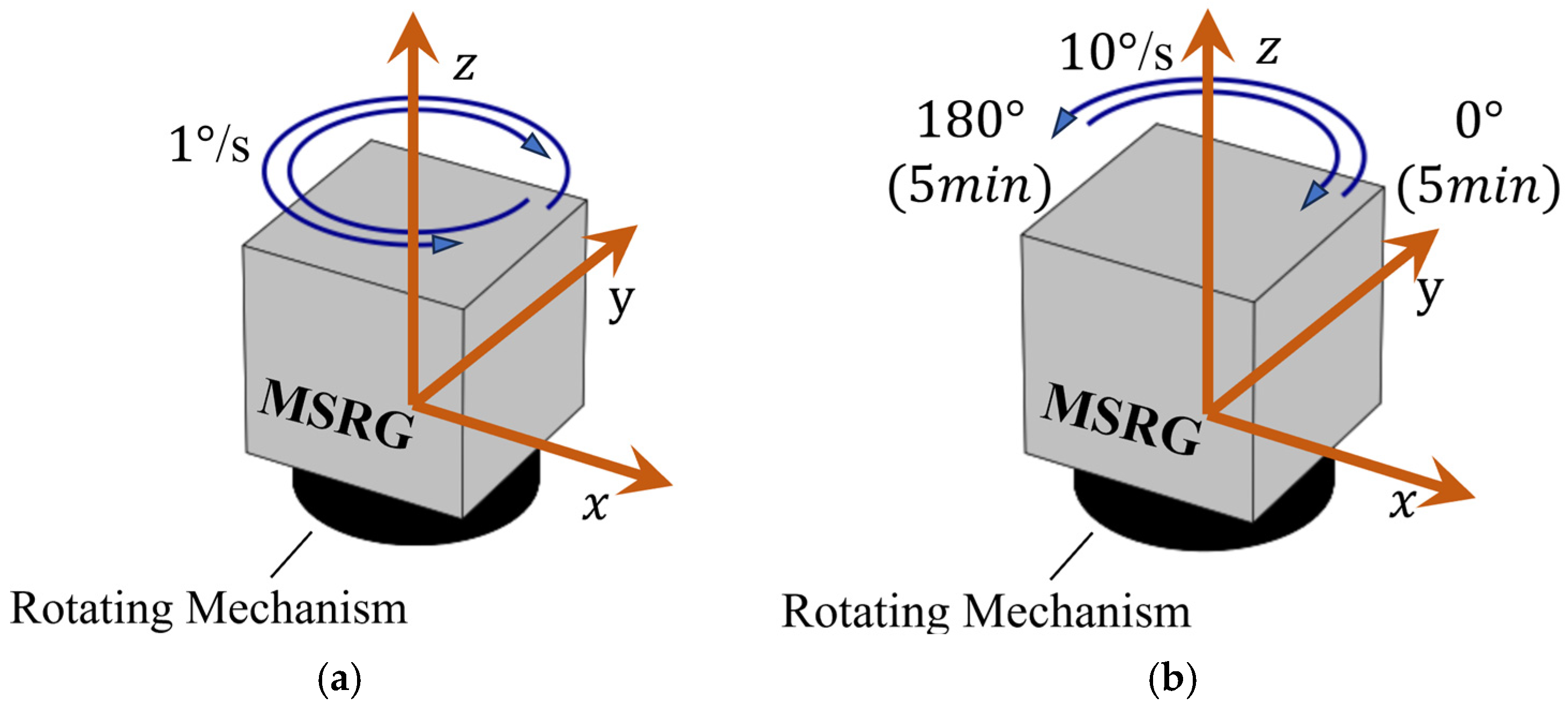
  • An error analysis was conducted on the MSRG-specific bias. A reciprocating rotation path with a period of 4π was designed. Additionally, LDV was integrated to provide velocity observations for the MSRG–RINS, thereby enhancing the accuracy and robustness of the system state estimation.
Figure 2. Comprehensive autonomous navigation strategy framework for MSRG–RINS: (a) magnetometer-assisted coarse alignment; (b) virtual rotation self-calibration; (c) earth rotation compensation; and (d) combined MSRG–RINS/LDV navigation method.
Drones 09 00706 g002

2. Initial Self-Alignment Method Based on STEKF and Rotary Modulation

To accommodate the dynamic characteristics of the MSRG operating in whole-angle mode, a magnetometer-aided continuous-rotation initial self-alignment method was proposed. Leveraging the virtual-rotation self-calibration of the MSRG’s angular correlation bias, the approach significantly improves both the initial alignment and the subsequent navigation performance of the MSRG–RINS. Because the calibration forces the MSRG output to be a zero-mean angular-increment sequence, the earth-rate projection onto the sensor triad must be removed at the initial attitude. Therefore, a magnetometer was used to obtain the initial azimuth rapidly, enabling prompt earth-rate compensation for the calibrated outputs of MSRG and improving alignment speed. However, magnetic disturbances can corrupt the magnetometer-derived azimuth, which can lead to large initial misalignment angles (≥5–10°), while the higher noise of the MSRG slows filter convergence. To counteract these issues, the STEKF was employed for both initial alignment and navigation.

2.1. Virtual Rotation Self-Calibration Method Based on MSRG Pattern Angle Control

MSRG virtual rotation self-calibration: in force-rebalanced mode, electrostatic force steps the standing-wave pattern by 10° over 0–180° (18 points). At each position, the gyro is switched to whole-angle mode for static data capture. Ordinary-least-squares fitting establishes the output-versus-pattern-angle model.
The bias, ε g = ε x g ε y g ε z g T , of MSRG was modelled through in-depth analysis of the MSRG outputs at different pattern angle positions and a detailed exploration of the fitting results under various harmonic functions. The bias and pattern angle of the MSRG mainly show 2nd and 4th harmonic variations [42]. Based on this, the relationship between the bias and the pattern angle can be modeled according to Equation (1):
ε x g = ε 0 x g + ε g 2 c x cos 2 α g x + ε g 2 s x sin 2 α g x + ε g 4 c x cos 4 α g x + ε g 4 s x sin 4 α g x ε y g = ε 0 y g + ε g 2 c y cos 2 α g y + ε g 2 s y sin 2 α g y + ε g 4 c y cos 4 α g y + ε g 4 s y sin 4 α g y ε z g = ε 0 z g + ε g 2 c z cos 2 α g z + ε g 2 s z sin 2 α g x + ε g 4 c z cos 4 α g z + ε g 4 s z sin 4 α g z
In Equation (1), ε g 2 c x , ε g 2 c y , ε g 2 c z , ε g 2 s x , ε g 2 s y and ε g 2 s z represents the 2nd harmonic coefficients. ε g 4 c x , ε g 4 c y , ε g 4 c z , ε g 4 s x , ε g 4 s y and ε g 4 s z represents the 4th harmonic coefficients, while ε 0 x g , ε 0 y g and ε 0 z g denote the constant bias terms of MSRG. α g x , α g y and α g z represent the pattern angles in the three axes of the MSRG. The relationship between gyroscope output and pattern angle can be expressed by the following Equation (2):
F 2 s F 2 c F 4 s F 4 c I 3 ε g 2 s ε g 2 c ε g 4 s ε g 4 c ε 0 = 1 Δ t Δ θ g x Δ θ g y Δ θ g z
In Equation (2), Δ θ g x , Δ θ g y and Δ θ g z represent the angular increments output by the x-, y- and z-axes of the gyroscope during Δ t , respectively. I 3 represents the identity matrix. ε g 2 s = ε g 2 s x ε g 2 s y ε g 2 s z T , ε g 2 c = ε g 2 c x ε g 2 c y ε g 2 c z T are 2nd harmonic coefficients, ε g 4 s = ε g 4 s x ε g 4 s y ε g 4 s z T , ε g 4 c = ε g 4 c x ε g 4 c y ε g 4 c z T represent 4th harmonic coefficients. F 2 s , F 2 c , F 4 s , F 4 c represent the sum of the 2nd and 4th harmonic components within time Δ t , as shown in Equation (3):
F 2 s = diag Δ t s in 2 α g x Δ t d t Δ t s in 2 α g y Δ t d t Δ t s in 2 α g z Δ t d t F 2 c = diag Δ t cos 2 α g x Δ t d t Δ t cos 2 α g y Δ t d t Δ t cos 2 α g z Δ t d t F 4 s = diag Δ t s in 4 α g x Δ t d t Δ t s in 4 α g y Δ t d t Δ t s in 4 α g z Δ t d t F 4 c = diag Δ t cos 4 α g x Δ t d t Δ t cos 4 α g y Δ t d t Δ t cos 4 α g z Δ t d t
Based on the equation constructed from Equation (2), the ordinary least squares method was employed to solve for 12 harmonic coefficients and three constant biases:
ε g 2 s ε g 2 c ε g 4 s ε g 4 c ε 0 = F 2 s F 2 c F 4 s F 4 c I 3 F 2 s F 2 c F 4 s F 4 c I 3 1 F 2 s F 2 c F 4 s F 4 c I 3 1 Δ t Δ θ g x Δ θ g y Δ θ g z
These 15 parameters were then used to fit the functional relationship between the pattern angle and the gyroscope output, thereby achieving the bias calibration process at each pattern angle position. Compensation proceeds in three steps: (1) removing systematic bias at every point; (2) determining the initial azimuth by magnetometer; and (3) mapping the corrected data to the vehicle frame, yielding earth-rate projections on MSRG axes. Continuous full-circle excitation enables global error identification and correction. All coordinates in this paper are expressed in the North–East–Down (NED) frame.

2.2. Initial Alignment Algorithm Based on State-Transformation Kalman Filtering

To tackle MSRG whole-angle mode issues—broadband noise, unstable bias, and uncertain earth-rate projection—a magnetometer-aided composite alignment was introduced. First, magnetometer data provided a coarse heading; together with the MSRG virtual-calibration output, an earth-rate compensation model was built for rapid on-site calibration. The magnetometer also supplies an initial azimuth; however, a large misalignment remains (≥5–10°). A state-transformation extended Kalman filter (STEKF) was therefore employed; it strictly defined velocity errors within the same coordinate frame, as shown in Equation (5) and handled large misalignments. Zero-velocity updates plus initial position served as observations for fine alignment:
x ˙ = F x + G w z = v ˜ n 0 3 × 1 r ˜ L λ h r L λ h = H x + υ
In Equation (5), x = ( ϕ n ) T         ( δ v ϕ n ) T         ( δ r L λ h ) T         ( ε b ) T         ( b ) T T . where ϕ n , δ v ϕ n , δ r L λ h , ε b , and b represent the attitude error, velocity error, position error, gyroscope bias, and accelerometer bias, respectively. δ v ϕ n = δ v n v ˜ n × ϕ n is the new velocity error after the state transformation. F denotes the system matrix, G represents the noise input matrix, w is the gyroscope process noise, and υ is the observation noise. v ˜ n denotes the INS-derived velocity, r ˜ L λ h represents the INS-computed position, r L λ h is the observed position, and the alignment phase uses the initial point position. The specific STEKF method is detailed in reference [43]. The STEKF strictly defines the velocity error in the same coordinate system. H represents the observation matrix, which can be expressed in the following form:
H = v ˜ n × I 3 × 3 0 3 × 3 0 3 × 6 0 3 × 3 0 3 × 3 I 3 × 3 0 3 × 6
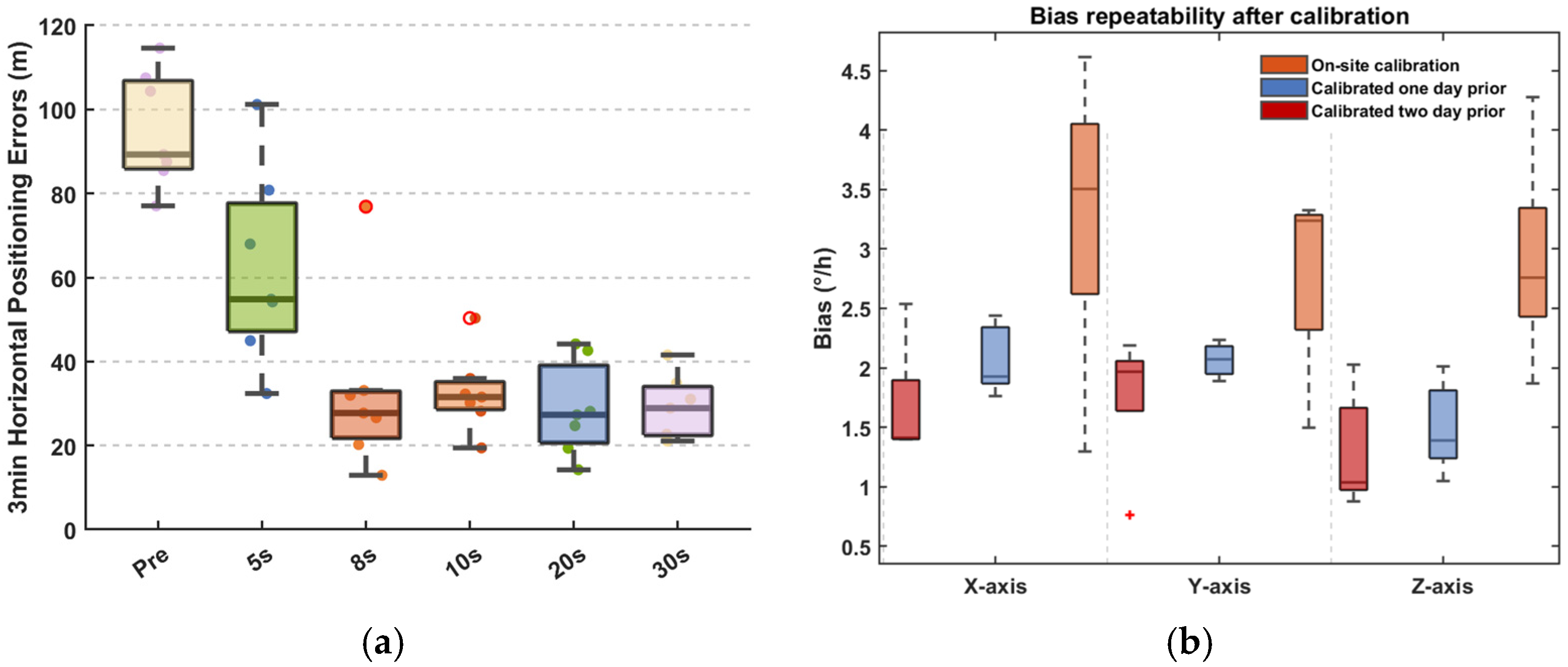
A three-minute pure inertial navigation test was conducted following alignment under different time parameters, with the heading changing by 120° and the horizontal angles changing by 15° at one-minute intervals (heading: 0°→120°→−240°; pitch/roll: 0°→15°→30°). The results are shown in Figure 3a. In Figure 3a, “pre” represents the three-minute pure inertial navigation result without virtual rotation self-calibration. The labels “5 s”, “8 s”, “10 s”, “20 s”, and “30 s” denote the time parameters for static data collection at each pattern angle position. Comparing the three-minute pure inertial navigation results after self-calibration using static data collected for 5 s, 8 s, 10 s, 20 s, and 30 s at each pattern angle position, it can be observed that the self-calibrated results are significantly better than the non-calibrated results. Furthermore, the results under the “10 s”, “20 s”, and “30 s” time parameters show little difference. Meanwhile, excessively short time parameters such as “5 s” and “8 s” yield suboptimal performance.
Additionally, a three-day test was conducted to evaluate the repeatability of the MSRG bias after virtual rotation self-calibration. The data for each day were divided into five groups. Parameters calibrated from the first group were used to calibrate the data for the next two days. As shown in Figure 3b, The MSRG bias exhibited minimal variation after recalibration at 24 h, with the X-axis and Y-axis biases remaining on the order of 2°/h and the Z-axis bias maintained at approximately 1.5°/h. However, a significant variation in the MSRG bias was observed after a 48 h interval, with values reaching, or exceeding, approximately 3°/h.
In summary, considering both time efficiency and navigation performance, an on-site calibration duration of 10 s is recommended as optimal and the pre-calibration procedure should not exceed a 2 -h interval.
Virtual rotation self-calibration offers substantial suppression of the angular correlation bias in MSRG. Nevertheless, complete elimination is precluded by the time constraints inherent in field calibration and the effects of temperature changes. Consequently, the residual bias detrimentally influences navigation precision. Accordingly, we present a method in the subsequent section that utilizes rotary modulation to mitigate the effect of these residual errors, in conjunction with velocity aiding from a LDV to further improve attitude determination and positioning accuracy.

3. LDV-Assisted RINS Based on MSRG

To address the bias residuals from incomplete MSRG self-calibration compensation, a small rotary mechanism was used to turn the MSRG-INS into a rotary inertial navigation system (RINS). This suppresses bias error accumulation. This section analyzes different rotary modulation techniques to identify the optimal method. It also calibrates the installation relationship between the MSRG and the rotary mechanism to determine the vehicle’s attitude. Moreover, velocity corrections for the MSRG–RINS are additionally derived via an integrated LDV.

3.1. Calibration of Rotary Modulation MSRG–RINS

RINS combines an MSRG–INS and a rotary mechanism. Installation errors between the MSRG–RINS and the rotary mechanism must be calibrated in advance. The method flow is shown in Figure 4. In the figure, O denotes the MSRG coordinate frame, and O’denotes the rotating mechanism coordinate frame, respectively.
The initial position of the MSRG–RINS is b 0 . After the rotating mechanism rotates through an angle α, it reaches position b . The rotation matrix from b 0 to the navigation coordinate system n can be given by Equation (7):
C b 0 n = C b n C b 0 b = C b n 1 0 ξ y 0 1 ξ x ξ y ξ x 1 cos α sin α 0 sin α cos α 0 0 0 1
ξ y and ξ x are the horizontal installation error angles between the MSRG–RINS and the rotary mechanism. C b n is the attitude matrix of the MSRG–RINS and C b 0 n is the vehicle’s attitude matrix after eliminating the rotation mechanism’s influence.
When α = 0 and α = π ,
C b 0 n = C b α = 0 n C b 0 b = C b α = 0 n 1 0 ξ y 0 1 ξ x ξ y ξ x 1 = C b α = π n C b 0 b = C b α = π n 1 0 ξ y 0 1 ξ x ξ y ξ x 1
Assuming that, as follows:
C b α = 0 n = c 11 α = 0 c 12 α = 0 c 13 α = 0 c 21 α = 0 c 22 α = 0 c 23 α = 0 c 31 α = 0 c 32 α = 0 c 33 α = 0 ,     C b α = π n = c 11 α = π c 12 α = π c 13 α = π c 21 α = π c 22 α = π c 23 α = π c 31 α = π c 32 α = π c 33 α = π
Solving Equation (9) yields the installation error angles.
ξ x = c 32 α = 0 + c 32 α = π c 33 α = 0 + c 33 α = π ,     ξ y = c 31 α = 0 c 31 α = π c 33 α = 0 + c 33 α = π
Finally, based on C b 0 n , the actual three Euler angles of the vehicle can be determined and the influence of the rotary mechanism can be eliminated.
The calibration tests employed 1000 s of MSRG–RINS alignment data, with the corresponding results detailed in Figure 5 and Table 2. Fog represents the attitude solution obtained from the FOG–INS. The results indicate that the proposed calibration method can effectively calibrate the installation error between the rotating mechanism and MSRG. The roll-angle error can be reduced from 0.5° to 0.03° and the pitch-angle error can be reduced from 0.14° to 0.02°.

3.2. Bias Error Analysis of Rotary Modulation Methods

Common single-axis rotary modulation schemes encompass continuous rotation, reciprocating rotation, and dual-position rotation. Continuous rotary modulation involves continuous clockwise or counterclockwise rotation, which cannot suppress scale-factor errors. Reciprocating rotary modulation involves continuous rotation with alternating directions at a constant speed, within a period. Dual-position rotary modulation is discontinuous, with the system pausing at 0° and 180° before rotating. The two modulation methods are illustrated in Figure 6.
The bias error of the MSRG varies with the azimuth angle of the standing wave in the form of even-order harmonics. Its bias model can be expressed in the form of Equation (1). Assuming that at the initial moment the body frame b0 and the IMU rotating coordinate system coincide, and that the IMU is controlled to rotate continuously around the vertical z-axis at an angular velocity ω, then the relationship between the body frame b0 and the IMU rotating frame b can be obtained as follows:
C b 0 b = cos ω t sin ω t 0 sin ω t cos ω t 0 0 0 1
To facilitate an intuitive analysis of the mechanism by which rotation modulation affects the constant errors of inertial sensors, we assumed that the navigation frame n coincides with the body frame b0. Under this assumption, the modulated expressions of the MSRG’s angular correlation bias ε n in the navigation frame n at time t are as follows:
ε n = C b 0 n C b b 0 ε x b ε y b ε z b = ε 0 x b cos ω t ε 0 y b sin ω t ε 0 x b sin ω t + ε 0 y b cos ω t ε 0 z b + N = 1 2 ε g ( 2 N ) c x cos 2 N α g x + N = 1 2 ε g ( 2 N ) s x sin 2 N α g x cos ω t N = 1 2 ε g ( 2 N ) c y cos 2 N α g y + N = 1 2 ε g ( 2 N ) s y sin 2 N α g y sin ω t N = 1 2 ε g ( 2 N ) c x cos 2 N α g x + N = 1 2 ε g ( 2 N ) s x sin 2 N α g x sin ω t + N = 1 2 ε g ( 2 N ) c y cos 2 N α g y + N = 1 2 ε g ( 2 N ) s y sin 2 N α g y cos ω t N = 1 2 ε g ( 2 N ) c z cos 2 N α g z + N = 1 2 ε g ( 2 N ) s z sin 2 N α g z
When the bias of the horizontal axis is consistent and other errors are ignored, the error caused by the bias of MSRG within a rotary modulation period T of the MSRG–RINS can be calculated. T 0 ° and T 180 ° are the stop times at 0° and 180° in the dual-position rotary modulation. T 0 ° + T 180 ° = T . In practice, the actual rotation angle of the MSRG is close to twice the pattern angle, but not exactly twice. The relationship between the pattern angle and the actual rotation angle is as follows: ω t = 2 ( α g t α g 0 ) , where α g t and α g 0 denote the pattern angles at time t and the initial time, respectively. The error within one period of dual-position rotary modulation can be calculated as follows:
T 0 ε n + T 180 ε n N = 1 2 ε g N s x sin 2 N α g x 0 T n = 1 2 ε g N s y sin 2 N α g y 0 T ε 0 z g T + ε g 4 c z T α g x 0 0 α g y 0 0 0 0 ε 0 z g T + ε g 4 c z T
The error caused by the bias of MSRG–RINS within a reciprocating rotary modulation cycle can be calculated as follows:
T ε n 0 0 ε 0 z g T
Under these assumptions, dual-position rotary modulation cannot eliminate errors from the 4th harmonic term of the azimuth bias of MSRG. In contrast, reciprocating rotary modulation can eliminate errors from even-harmonic terms of the azimuth bias of MSRG and better suppress errors from the horizontal bias of MSRG. Experiments (five runs each) confirmed that reciprocating rotary modulation outperformed dual-position: 3 min pure-inertial horizontal positioning accuracy improved by 29% (Table 3). Thus, reciprocating modulation is preferable for MSRG–RINS attitude measurement.
Here, positioning accuracy is evaluated using common metrics, notably RMS (Root Mean Square). In the experimental results presented in Table 3, the RMS value of the horizontal positioning errors from five experimental runs was calculated and reported as the positioning accuracy. Therefore, the mentioned improvement in horizontal positioning accuracy signifies an overall reduction in the magnitude of the horizontal positioning error. In Table 3, “Dual-position (Calibrated)” denotes the dual-position rotational modulation alignment method following virtual rotation self-calibration, while “Reciprocation (Calibrated)” denotes the reciprocating rotational modulation alignment method following virtual rotation self-calibration.
The inherent drift in the velocity solution from a standalone MSRG–RINS prevents it from meeting practical navigation requirements. To compensate for this, the subsequent section presents a filtering methodology that incorporates LDV-derived velocity as an external observation.

3.3. Combined RINS/LDV Navigation Method Based on STEKF

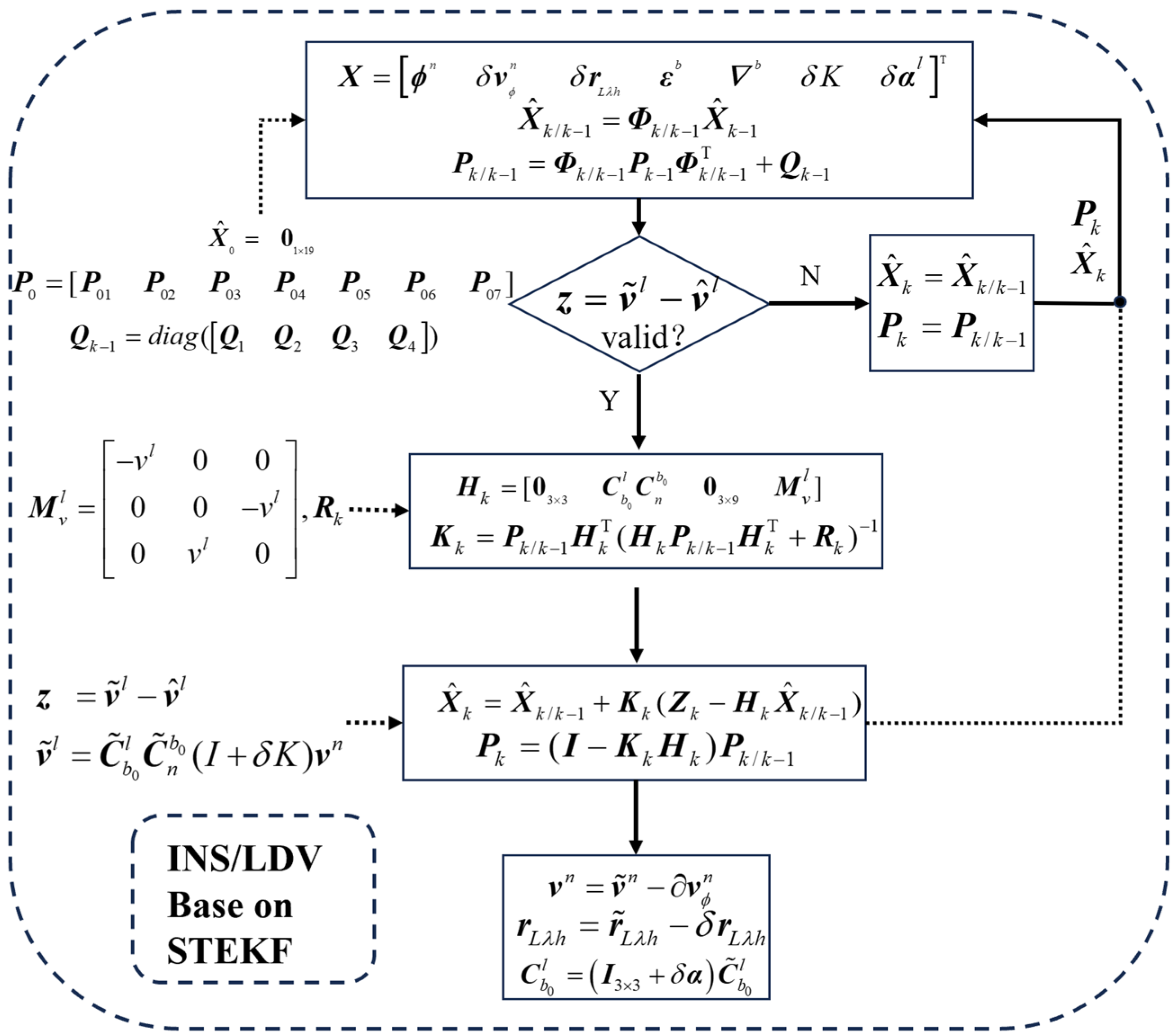
The combination of a LDV and an inertial navigation system was used in the experiment and the method used is shown in Figure 7.
Taking the velocity measured by LDV as the observation, the LDV scale factor δ K and the installation error angles δ α = [ δ α y δ α z ] were augmented into the state vector for estimation. Because the roll installation error of the LDV has no influence on the velocity computation, only the heading and pitch installation error angles were estimated. Figure 7 variable definitions are as follows:
X : System state vector; X ^ k / k 1 : One-step predicted state; P k : State covariance matrix; P 0 : Initial state covariance matrix; Φ k / k 1 : System discretized state transition matrix; Q k 1 : Process noise covariance matrix; v ˜ l : Projection of the INS-derived velocity in the LDV frame; v ^ l : LDV observed velocity; H k : Observation matrix; R k : Observation noise covariance matrix; v ˜ n : INS-derived velocity in the navigation frame (n-frame); r ˜ L λ h : INS-derived position; C b 0 l : Rotation matrix from the b0-frame to the LDV frame (l-frame); C ˜ n b 0 : Rotation matrix from the navigation frame (n-frame) to the b0-frame.
In order to evaluate the performance of the method presented above, an experimental analysis based on a vehicle test was carried out and is described in the following section. Furthermore, a comprehensive description of the sensor devices utilized in this study is provided.

4. Experiment

To verify the effectiveness of the proposed method, practical in-vehicle dynamic experiments were conducted. First, the technical specifications of the MSRG and the experimental scenarios for testing are provided.

4.1. Technical Indicators of the MSRG and LDV

To comprehensively evaluate the key performance metrics of the employed MSRG, static data were collected along its three axes for a duration of 2.5 h and subjected to Allan variance analysis. The Allan variance serves as a standard methodology for assessing the stochastic error characteristics of inertial sensors. It enables clear identification and quantification of the influences from various noise sources on the sensor output. The relationship curve of the analysis results over time—specifically, the Allan standard deviation plot—can reveal the dominant error factors across different time scales.
This method establishes the relationship between sensor errors and time-correlation functions by calculating the two-sample variance of the output data over different averaging times. In the log–log plot of the Allan standard deviation, specific slope regions of the curve correspond to different types of stochastic errors. For instance, a region with a slope of −1/2 typically represents the angle random walk (ARW), which characterizes the high-frequency white noise of the sensor and directly affects the short-term accuracy of attitude or velocity integration. Conversely, the plateau region of the curve (i.e., the “trough” area with a zero slope) corresponds to bias instability, which is a key indicator determining the duration for which the system can maintain reliable navigation without external aiding. The ARW can be determined using the following formula:
A R W ( ° / h ) = σ A ( T = 1 ) ( ° / h ) s = σ A ( T = 1 ) 60 ( ° / h )
Through Allan variance analysis of the triaxial static data from the MSRG, key metrics, including bias instability and angle random walk (ARW) were accurately determined. The analysis results are clearly presented in the Allan deviation plot shown in Figure 8. The additional specifications of the MSRG IMU and the technical parameters of the employed LDV are summarized in Table 4.
As can be seen from Figure 8, the three-axis bias instability of the MSRG used in the experiment were determined to be 0.59°/h, 0.27°/h, and 0.25°/h, respectively. The corresponding three-axis angle random walk (ARW) values were 0.12°/√h, 0.08°/√h, and 0.06°/√h, respectively. The specifications of the MSRG–RINS accelerometers are sourced from the product manual. The physical diagram and system architecture of the MSRG–RINS are shown in Figure 9.

4.2. UGV Autonomous Navigation Experiments

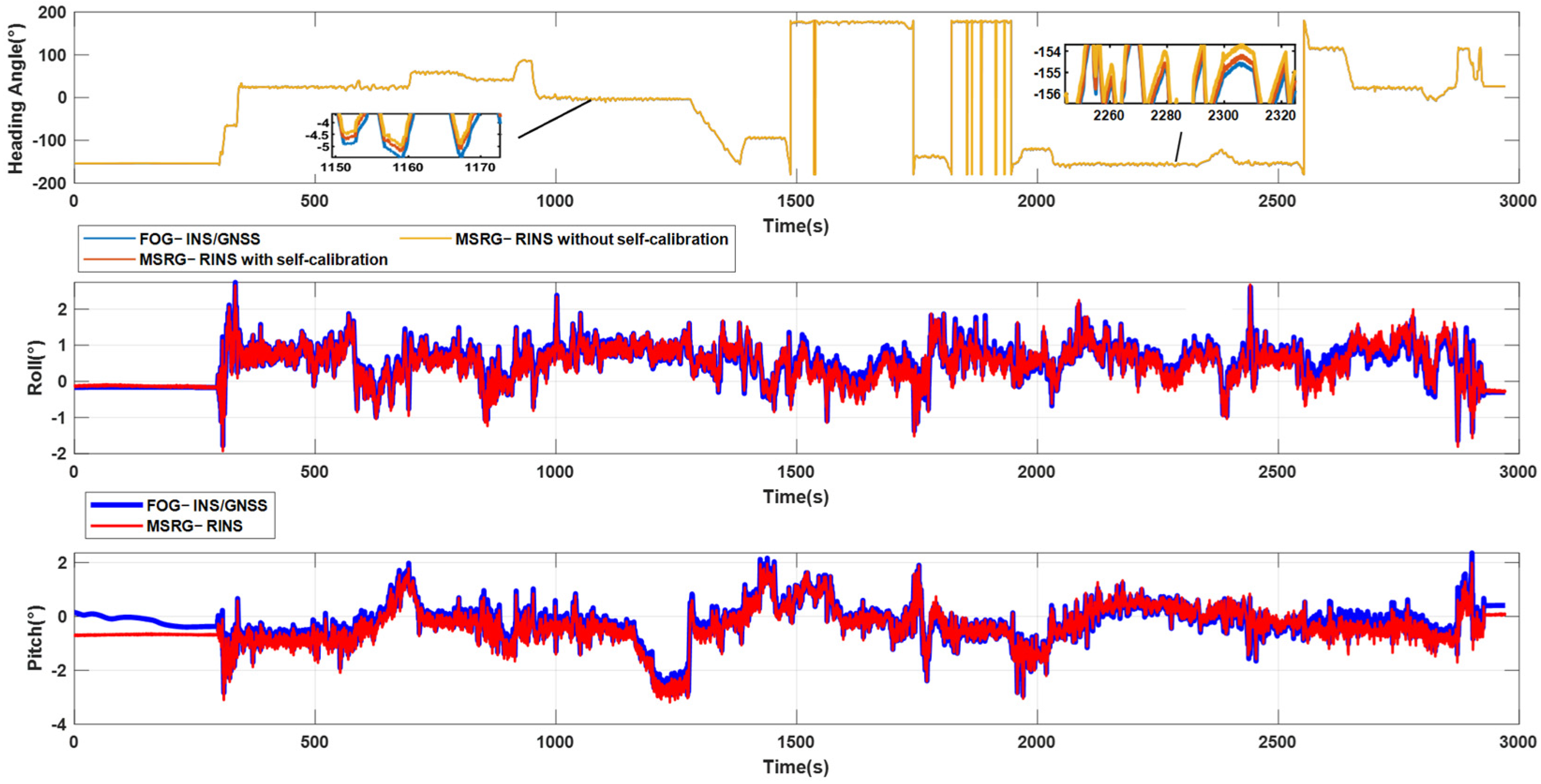
To verify the effectiveness of the proposed method in dynamic attitude measurement, an in-vehicle dynamic experiment with an accumulated trajectory length of approximately 3.7 km were executed. In the experiment, static initial alignment was carried out for 1000 s. The experimental platform is shown in Figure 10 and Figure 11, with a FOG–INS (with an attitude accuracy of ±0.01°) serving as the reference. The UGV employed for the on-board experiments shown in Figure 10 is the Hunter 2.0.
Hunter 2.0 is an Ackermann-steer, programmable UGV featuring an automotive-style chassis. Compared with four-wheel differential platforms, the mechanical architecture of Hunter 2.0 confers pronounced advantages in both payload capacity and maximum velocity, thereby affording an ample margin for the flexible integration of multi-source payloads and the rapid iteration of algorithms. Consequently, it constitutes an ideal platform for unmanned systems experimentation. It is also well-suited for unmanned inspection, security, scientific research, exploration, logistics, and related applications. The specific parameters of the Hunter 2.0 used are shown in Table 5.
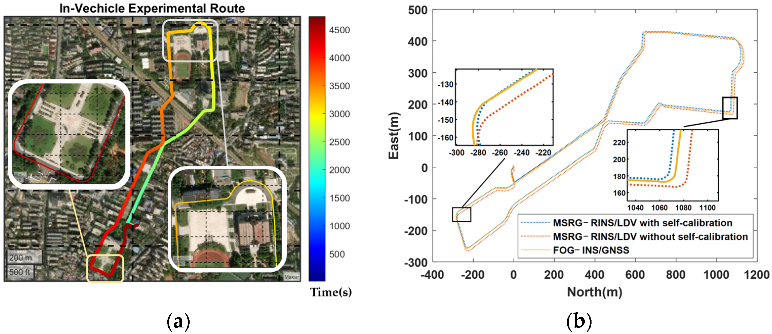
The attitude and positioning results, heading error, and horizontal position error of the LDV-aided MSRG–RINS during the vehicle-borne experimental are presented in Table 6 and Figure 12, Figure 13 and Figure 14. Figure 13 illustrates the experimental route. The color scale on the left indicates the operational time.
In Figure 12, “FOG–INS/GNSS” denotes the navigation results from the fiber-optic gyro INS integrated with GNSS, which serves as the reference in this experiment. The label “self-calibration” refers to the virtual rotation self-calibration method. The results demonstrate that the attitude solutions from the MSRG–RINS after virtual rotation-based self-calibration show closer alignment with the reference trajectory.
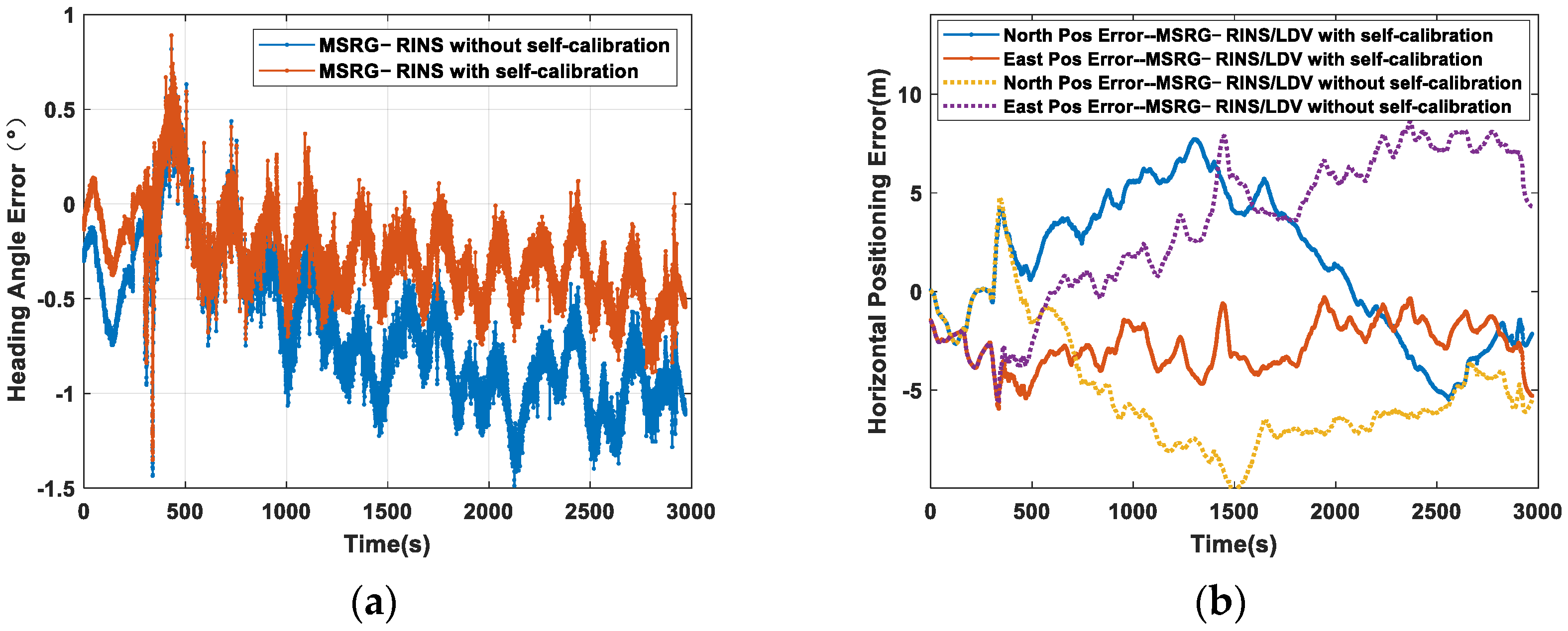
In Figure 13 and Figure 14, the label “self-calibration” also refers to the virtual rotation self-calibration method. The label “MSRG–RINS/LDV” denotes the integrated navigation positioning solution utilizing LDV velocity observations. The results presented in the figure further demonstrate that the introduction of virtual rotation-based self-calibration leads to a significant improvement in both the attitude determination and positioning accuracy of the system. Furthermore, with the aid of LDV, the estimated solutions exhibit even closer agreement with the reference, thereby fully validating the effectiveness and reliability of the proposed method in practical engineering applications.
In Table 6, “Calibrated” denotes the navigation results obtained after applying the virtual rotation self-calibration method, while “Uncalibrated” refers to the results without its application. “Pure-INS Heading Error” represents the heading attitude error under pure-inertial attitude solution of the MSRG–RINS. RMS indicates the root mean square. The heading error was obtained by calculating the difference between the heading attitude derived from the MSRG–RINS solution and the reference heading attitude provided by the FOG–INS/GNSS integrated navigation system. The root mean square (RMS) was then computed from the overall error dataset. The same methodology was applied to determine the horizontal attitude error and the horizontal positioning error. “Odometric Error” is defined as the ratio of the maximum horizontal positioning error to the total traveled distance.
As indicated by Table 6 and Figure 12, Figure 13 and Figure 14, the MSRG–RINS demonstrates effective attitude measurement in dynamic environments, achieving a heading error that does not exceed 0.35° and a horizontal attitude error of 0.17° within 3000 s. The attitude measurement and horizontal positioning error with and without virtual rotation self-calibration were also compared. Experimental results of the MSRG–RINS/LDV-integrated navigation show that after virtual rotation self-calibration, the MSRG–RINS’s heading attitude precision was enhanced by 53%, and the horizontal positioning precision was enhanced by 27%.

5. Conclusions

This investigation targeted all-weather, all-scenario autonomy for small-scale UGVs and proposed an LDV-aided navigation framework built on MSRG–RINS. The MSRG IMU was employed as the core sensor, offering superior SWaP characteristics and a wide bandwidth that preserved angular rate fidelity during emergency avoidance or aggressive turns. To mitigate the angular correlation bias inherent to WA mode, a virtual rotation self-calibration method was developed: the device was sequentially switched to FB mode to set the modal angle to 18 discrete orientations, followed by static data collection in WA mode and least-squares estimation of the bias. Multiple experiments established the following parameters for virtual rotation self-calibration: an optimal duration of 10 s and a maximum pre-calibration interval of 24 h. However, residual errors nevertheless persisted and degraded attitude determination; thus, rotary modulation was adopted for further suppression. Conventional analyses typically account for constant biases only. In contrast, this study developed an error-propagation model that explicitly incorporates the angular correlation bias of the MSRG. Multiple experimental results demonstrated that the reciprocating rotary modulation method achieved a 29% improvement in horizontal positioning precision over a 3 min pure inertial navigation period after alignment, compared to the dual-position rotational modulation method.
Prior to the formal experiments, this study characterized the MSRG’s performance through Allan variance analysis, measuring bias instabilities of 0.59°/h, 0.27°/h, and 0.25°/h, along with angle random walk (ARW) values of 0.12°/√h, 0.08°/√h, and 0.06°/√h along the three axes. Despite its wide bandwidth and superior dynamic response, the MSRG suffers from higher gyro noise (ARW > 0.06°/√h) and requires earth-rate compensation after virtual rotation self-calibration. Consequently, conventional initial-alignment schemes are incompatible with this sensor. To resolve this, this paper proposed a magnetometer-aided, reciprocating-rotation initial-alignment method based on STEKF. In addition, LDV velocity measurements were incorporated as external observations to enhance the positioning accuracy of the MSRG–RINS. An 18-state STEKF was formulated to simultaneously estimate attitude and position while on-line calibrating LDV installation errors and scale factors, yielding a significant improvement in navigation performance. In a 3.7 km dynamic vehicle experiment, the virtual rotation self-calibration reduced the MSRG–RINS heading error by 53% and improved the positioning accuracy of MSRG–RINS/LDV integration navigation by 27%. During a 3000 s pure-inertial phase the MSRG–RINS maintained a heading error of 0.35°. With LDV aiding, the system achieved a positioning error of 4.9 m (RMSE), corresponding to a total odometric error of 0.24%. These results demonstrate the engineering viability of the proposed approach.
The current method also has certain limitations. The virtual rotation-based self-calibration must be performed under static conditions and cannot be applied in dynamic scenarios. Future work will explore the implementation of virtual rotation self-calibration via Kalman filtering to extend its applicability to dynamic environments. Additionally, the current MSRG still relies on an external rotating mechanism for rotational modulation, which inevitably introduces additional noise and errors, thereby affecting navigation accuracy to some extent. Future work will extend the MSRG–RINS to three-dimensional, high-dynamic scenarios such as airborne platforms, underwater vehicles and humanoid robots, and will further exploit intrinsic MSRG capabilities—including virtual rotation modulation and the cooperative alternation of FB and WA modes.

Author Contributions

Conceptualization, T.M. and W.W.; methodology, T.M., W.W. and H.C.; investigation, H.C.; validation, H.C., Y.W., L.C., Y.K. and H.S.; resources, T.M., W.W., Y.Z., J.S. and X.X.; writing—original draft preparation, H.C.; writing—review and editing, H.C., T.M. and W.W.; supervision, W.W.; project administration, T.M.; funding acquisition, T.M. All authors have read and agreed to the published version of the manuscript.

Funding

This research was funded by National Natural Science Foundation of China, grant number 62304255.

Data Availability Statement

The datasets collected and generated in this study are available upon request to the corresponding author.

Conflicts of Interest

The authors declare no conflicts of interest.

Abbreviations

The following abbreviations are used in this manuscript:
ARWAngle Random Walk
FOGFiber Optic Gyroscope
IMUInertial Measurement Unit
LDVLaser Doppler Velocimetry
MEMSMicro-Electro-Mechanical System
MSRGMicro-Shell Resonator Gyroscope
RINSRotary Inertial Navigation System
MSRG–IMUMicro-Shell Resonator Gyroscope Inertial Measurement Unit
STEKFState-Transformation Extended Kalman Filter
SWaPSize, Weight and Power
SINSStrapdown Inertial Navigation System
UGVsUnmanned Ground Vehicles

References

  1. Sapkota, R.; Roumeliotis, K.I.; Karkee, M. UAVs Meet Agentic AI: A Multidomain Survey of Autonomous Aerial Intelligence and Agentic UAVs. arXiv 2025, arXiv:2506.08045. [Google Scholar] [CrossRef]
  2. Shahar, F.S.; Sultan, M.T.H.; Nowakowski, M.; Bukaszewicz, A. UGV-UAV Integration Advancements for Coordinated Missions: A Review. J. Intell. Robot. Syst. 2025, 111, 69. [Google Scholar] [CrossRef]
  3. Qin, H.; Shao, S.; Wang, T.; Yu, X.; Jiang, Y.; Cao, Z. Review of Autonomous Path Planning Algorithms for Mobile Robots. Drones 2023, 7, 211. [Google Scholar] [CrossRef]
  4. Yang, C.; Fan, Z.; Zhu, Q.; Yang, P.; Mei, C.; Lu, B. Robust navigation system for UGV based on the IMU/vision/geomagnetic fusion. Int. J. Intell. Robot. 2023, 7, 321–334. [Google Scholar] [CrossRef]
  5. Ioannides, R.T.; Pany, T.; Gibbons, G. Known Vulnerabilities of Global Navigation Satellite Systems, Status, and Potential Mitigation Techniques. Proc. IEEE 2016, 104, 1174–1194. [Google Scholar] [CrossRef]
  6. Zangenehnejad, F.; Gao, Y. GNSS smartphones positioning: Advances, challenges, opportunities, and future perspectives. Satell. Navig. 2021, 2, 24. [Google Scholar] [CrossRef]
  7. Lušić, Z.; Pinčetić, T.; Esko Krančević, P. The role of celestial navigation in modern day and future navigation. In Proceedings of the 10th International Conference on Maritime Transport, Barcelona, Spain, 5–7 June 2024. [Google Scholar]
  8. Chen, K.; Liang, W.; Zeng, C.; Guan, R. Multi-geomagnetic-component assisted localization algorithm for hypersonic vehicles. J. Zhejiang Univ. A Sci. 2021, 22, 357–368. [Google Scholar] [CrossRef]
  9. Zidan, J.; Adegoke, E.I.; Kampert, E.; Birrell, S.A.; Ford, C.R.; Higgins, M.D. GNSS Vulnerabilities and Existing Solutions: A Review of the Literature. IEEE Access 2021, 9, 153960–153976. [Google Scholar] [CrossRef]
  10. Yan, Z.; Yu, H.; Leng, Z.; Yao, Y.; Zhao, X.; Wang, Z. Comprehensive interference estimation and correction methods based on Unscented Kalman Filter for magnetic anomaly detection. Meas. J. Int. Meas. Confed. 2025, 248, 116858. [Google Scholar] [CrossRef]
  11. Huang, L.; Wang, Z.; Xiong, Q.; Qu, R.; Yao, C.; Li, C. Mamba-VNPS: A Visual Navigation and Positioning System with State-Selection Space. Drones 2024, 8, 663. [Google Scholar] [CrossRef]
  12. Cai, W.; Huang, S.; Cheng, G.; Long, Y.; Gao, P.; Sun, C.; Dong, H. Bridging Zero-shot Object Navigation and Foundation Models through Pixel-Guided Navigation Skill. In Proceedings of the 2024 IEEE International Conference on Robotics and Automation (ICRA), Yokohama, Japan, 13–17 May 2024. [Google Scholar]
  13. Shan, T.; Englot, B. LeGO-LOAM: Lightweight and Ground-Optimized Lidar Odometry and Mapping on Variable Terrain. In Proceedings of the 2018 IEEE/RSJ International Conference on Intelligent Robots and Systems (IROS), Madrid, Spain, 1–5 October 2018; pp. 4758–4765. [Google Scholar]
  14. Zheng, C.; Xu, W.; Zou, Z.; Hua, T.; Yuan, C.; He, D.; Zhou, B.; Liu, Z.; Lin, J.; Zhu, F.; et al. FAST-LIVO2: Fast, Direct LiDAR–Inertial–Visual Odometry. IEEE Trans. Robot. 2025, 41, 326–346. [Google Scholar] [CrossRef]
  15. Gao, J.; Li, K.; Chen, Y. Study on Integration of FOG Single-Axis Rotational INS and Odometer for Land Vehicle. IEEE Sens. J. 2018, 18, 752–763. [Google Scholar] [CrossRef]
  16. Poletti, L.; Sanchis, D.S.; Siryani, R. A direct approach for high-quality MEMS based IMU/INS production. In Proceedings of the Conference on DGON Inertial Sensors and Systems, Braunschweig, Germany, 15–16 September 2020; pp. 1–19. [Google Scholar]
  17. Sun, W.; Huang, H.; Sun, P.; Ding, W. MEMS strapdown inertial attitude measurement system using rotational modulation technology. PLoS ONE 2024, 19, e298168. [Google Scholar] [CrossRef] [PubMed]
  18. Qin, T.; Li, P.; Shen, S. VINS-Mono: A Robust and Versatile Monocular Visual-Inertial State Estimator. IEEE Trans. Robot. 2018, 34, 1004–1020. [Google Scholar] [CrossRef]
  19. Zhang, L.; Ye, W.; Yan, J.; Zhang, H.; Betz, J.; Yin, H. Loosely Coupled Stereo VINS Based on Point-Line Features Tracking With Feedback Loops. IEEE Trans. Veh. Technol. 2024, 73, 10916–10931. [Google Scholar] [CrossRef]
  20. Long, Z.; Xiang, Y.; Lei, X.; Li, Y.; Hu, Z.; Dai, X. Integrated Indoor Positioning System of Greenhouse Robot Based on UWB/IMU/ODOM/LIDAR. Sensors 2022, 22, 4819. [Google Scholar] [CrossRef]
  21. Han, X.; Li, H.; Hui, N.; Zhang, J.; Yue, G. A Multi-Sensor Fusion-Based Localization Method for a Magnetic Adhesion Wall-Climbing Robot. Sensors 2025, 25, 5051. [Google Scholar] [CrossRef]
  22. He, L.; Li, B.; Chen, G. PLACE-LIO: Plane-Centric LiDAR-Inertial Odometry. IEEE Robot. Autom. Lett. 2025, 10, 6231–6238. [Google Scholar] [CrossRef]
  23. Deng, Y.; Zhang, W.; Li, W.; Zhou, S.; Zhao, X.; Chen, W. OWP-LIO: A method and experimental study for pose measurement of offshore wind power O&M vessels using Lidar-Inertial odometry. Ocean Eng. 2025, 317, 120107. [Google Scholar] [CrossRef]
  24. Zhang, H.; Wang, D.; Huo, J. Mounting Misalignment and Time Offset Self-Calibration Online Optimization Method for Vehicular Visual-Inertial-Wheel Odometer System. IEEE Trans. Instrum. Meas. 2024, 73, 1–13. [Google Scholar] [CrossRef]
  25. Xu, W.; Zhang, F. FAST-LIO: A Fast, Robust LiDAR-Inertial Odometry Package by Tightly-Coupled Iterated Kalman Filter. IEEE Robot. Autom. Lett. 2021, 6, 3317–3324. [Google Scholar] [CrossRef]
  26. Zhou, J.; Nie, X.; Lin, J. A novel laser Doppler velocimeter and its integrated navigation system with strapdown inertial navigation. Opt. Laser Technol. 2014, 64, 319–323. [Google Scholar] [CrossRef]
  27. Xiang, Z.; Wang, Q.; Huang, R.; Xi, C.; Nie, X.; Zhou, J. A Fast Robust In-Motion Alignment Method for Laser Doppler Velocimeter-Aided Strapdown Inertial Navigation System. IEEE Sens. J. 2022, 22, 17254–17265. [Google Scholar] [CrossRef]
  28. Xiang, Z.; Wang, Q.; Huang, R.; Jin, S.; Nie, X.; Zhou, J. A Robust Online Calibration Method for SINS/LDV Integrated Navigation System Based on Position Observation. IEEE Sens. J. 2024, 24, 895–908. [Google Scholar] [CrossRef]
  29. Zhu, Y.; Wang, X.; Zheng, J.; Xiong, H.; Zhao, Y. Using GPS Time-Differenced Carrier Phase Observations to Calibrate LDV/INS Integrated Navigation Systems. IEEE Sens. J. 2020, 20, 405–414. [Google Scholar] [CrossRef]
  30. Li, B.; Li, Z.; Wang, X.; Huang, C.; Yang, B. 4.11-million Q-factor whole-angle MEMS hemispherical resonator gyroscope with 0.013°/h bias instability. Meas. Sci. Technol. 2024, 35, 115116. [Google Scholar] [CrossRef]
  31. Ding, X.; Ruan, Z.; Pu, Y.; Zhang, H.; Li, H.; Zhao, L. Bias Modulation of Force-to-Rebalanced Micro Hemispherical Resonator Gyroscope Based on Mode-Rotation. IEEE Sens. J. 2022, 22, 15802–15816. [Google Scholar] [CrossRef]
  32. Chen, W.; Ding, X.; Qin, Z.; Li, H. Modeling, Characterization, and Compensation of Detection and Actuation Coupling Errors for Whole-Angle Micro Hemispherical Resonant Gyroscope. IEEE Trans. Instrum. Meas. 2024, 73, 1–14. [Google Scholar] [CrossRef]
  33. Nan, F.; Gao, Z.; Han, Y.; Cui, H.; Shang, L.; Zhang, Y. Self-calibration for phase shift in Coriolis vibratory gyroscope with whole-angle mode operation. Measurement 2025, 242, 116043. [Google Scholar] [CrossRef]
  34. Chen, W.; Ding, A.; Ding, X.; Li, H. A Novel Phase Error Quantitative Characterization Method for Whole-Angle Micro Hemispherical Resonant Gyroscope. In Proceedings of the 2024 IEEE SENSORS, Kobe, Japan, 20–23 October 2024; pp. 1–4. [Google Scholar]
  35. Sun, J.; Yu, S.; Zhang, Y.; Li, Q.; Xi, X.; Lu, K.; Wu, X.; Xiao, D. 0.79 ppm scale-factor nonlinearity whole-angle microshell gyroscope realized by real-time calibration of capacitive displacement detection. Microsyst. Nanoeng. 2021, 7, 79. [Google Scholar] [CrossRef]
  36. Han, H.; Wang, L.; Wang, M. A Dynamic Gyro Scale Factor Error Calibration Method for RINSs. IEEE Sens. J. 2021, 21, 20817–20823. [Google Scholar] [CrossRef]
  37. Gargiulo, A.M.; di Stefano, I.; Genova, A. Model-Based Slippage Estimation to Enhance Planetary Rover Localization with Wheel Odometry. Appl. Sci. 2021, 11, 5490. [Google Scholar] [CrossRef]
  38. Zhang, H.; Fan, C.; Teng, L.; He, X.; Zhou, W.; Zhang, L. POL-VIO: A Visual Inertial Odometry with Polarization Skylight Compass in Challenge Environment. IEEE Robot. Autom. Lett. 2025, 10, 1–8. [Google Scholar] [CrossRef]
  39. Li, W.; Wang, G.; Zhang, Q.; Liu, J. LG-VIWO: Visual-Inertial-Wheel Odometry Leveraging the Depth-Aided Local Ground Constraints for Mobile Robots. IEEE Trans. Instrum. Meas. 2025, 74, 8507911. [Google Scholar] [CrossRef]
  40. Wu, Y.; Kuang, J.; Niu, X. Wheel-INS2: Multiple MEMS IMU-Based Dead Reckoning System With Different Configurations for Wheeled Robots. IEEE Trans. Intell. Transp. Syst. 2023, 24, 3064–3077. [Google Scholar] [CrossRef]
  41. Tan, C. Dead Reckoning Localization Using a Single Wheel-Mounted IMU With the Simultaneous Estimation of Mounting Parameters. IEEE Sens. J. 2024, 24, 3797–3810. [Google Scholar] [CrossRef]
  42. Deng, K.; Pan, Y.; Xiao, P.; Tang, X.; Li, J.; Xia, T.; Yuan, J. Separation, Identification, and Compensation of Damping, Detection, and Actuation Errors for Rate-Integrating Hemispherical Resonator Gyroscopes. IEEE Trans. Instrum. Meas. 2025, 74, 1–13. [Google Scholar] [CrossRef]
  43. Wang, M.; Wu, W.; Zhou, P.; He, X. State transformation extended Kalman filter for GPS/SINS tightly coupled integration. GPS Solut. 2018, 22, 112. [Google Scholar] [CrossRef]
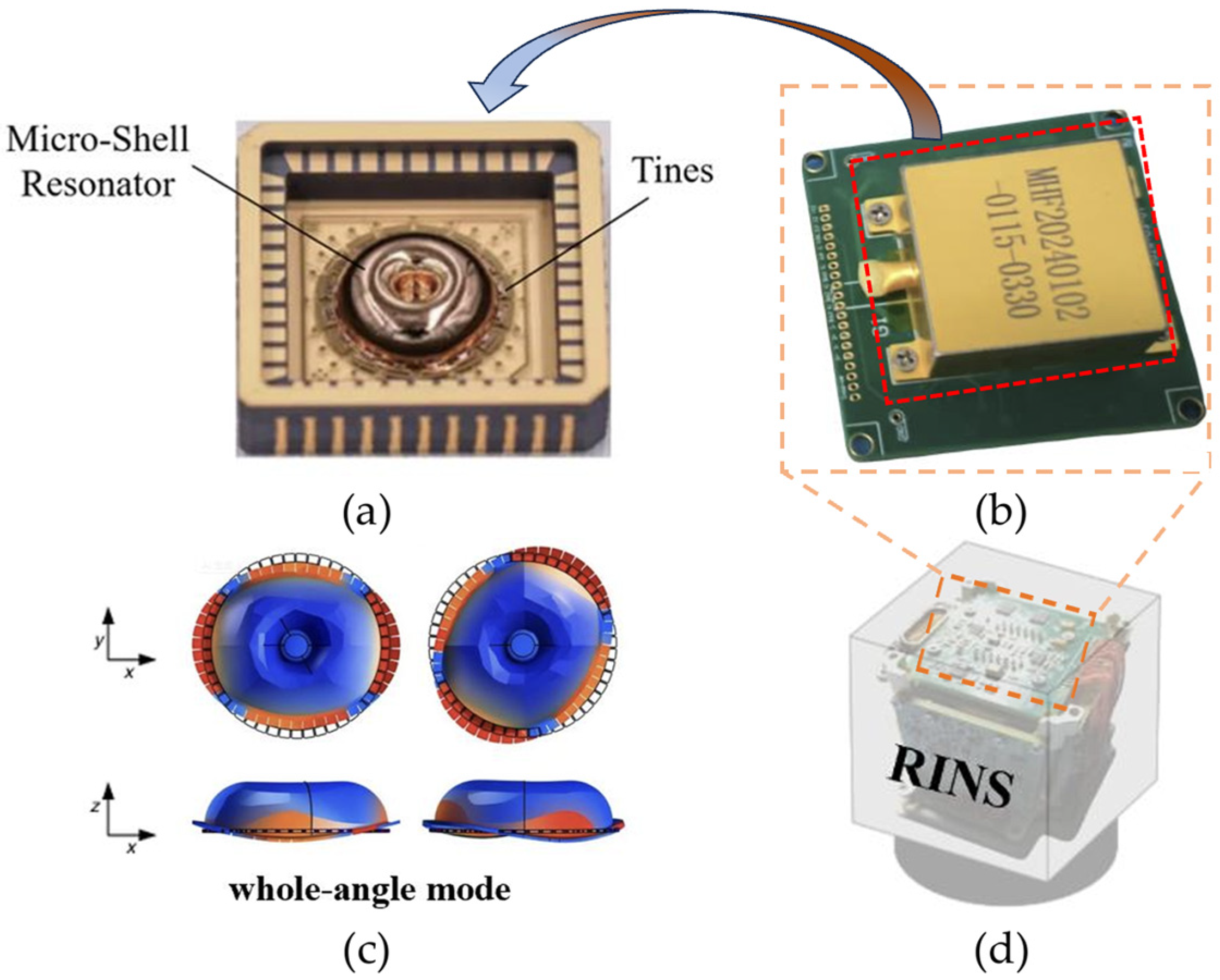
Figure 1. MSRG hardware diagram and working mode: (a) MSRG; (b) MSRG electronic circuit board; (c) whole-angle working mode; and (d) MSRG–RINS.
Drones 09 00706 g001
Figure 3. The effectiveness of virtual rotation self-calibration for MSRG–RINS. The outliers are indicated in red: (a) comparison of initial alignment performance across different time parameters; and (b) bias repeatability after virtual rotation self-calibration.
Drones 09 00706 g003
Figure 4. Schematic diagram of the calibration method for installation errors between the MSRG IMU and the rotating mechanism in an MSRG–RINS.
Drones 09 00706 g004
Figure 5. Comparison of horizontal attitude angles from the MSRG–RINS before and after installation errors calibration versus the reference of FOG–INS: (a) roll angle; and (b) pitch angle.
Drones 09 00706 g005
Figure 6. MSRG–RINS rotation modulation method: (a) reciprocating rotary modulation; and (b) dual-position rotary modulation.
Drones 09 00706 g006
Figure 7. Architecture of the STEKF-based filter for the MSRG–RINS and LDV integrated navigation system.
Drones 09 00706 g007
Figure 8. Analysis results of Allan variance for MSRG: (a) X-axis; (b) Y-axis; and (c) Z-axis.
Drones 09 00706 g008
Figure 9. Overall system architecture of the MSRG–RINS and the data processing and communication architecture of its computing unit: (a) MSRG–RINS and the RK-3588-based computing unit; and (b) data processing and communication architecture of the computing unit.
Drones 09 00706 g009
Figure 10. The UGV employed in this in-vehicle experiment, along with its specific model.
Drones 09 00706 g010
Figure 11. Spatial layout of velocity sensors, inertial sensors, and the reference system in the experimental platform.
Drones 09 00706 g011
Figure 12. Comparison of attitude solutions from the MSRG–RINS in pure inertial navigation versus the FOG–INS/GNSS integrated navigation system.
Drones 09 00706 g012
Figure 13. In-vehicle experimental routes and comparison of horizontal positioning solutions: (a) in-vehicle experimental routes; and (b) comparison of horizontal position.
Drones 09 00706 g013
Figure 14. Analysis of heading and horizontal positioning errors for the LDV-assisted MSRG–RINS in the vehicle-borne experimental: (a) comparison of heading angle error; and (b) comparison of positioning error.
Drones 09 00706 g014
Table 1. Frontiers in navigation methodologies.
MethodHeading
Error
PRMSEOdometric
Error
Publication DateExplanation
Anna Maria Gargiulo et al. [37]4% (500 m)2021Inertial-Wheel Odometry
POL-VIO [38]1.82°8.77 m—(4.9 km)2025Visual Inertial Odometry
LG-VIWO [39]10.6 m—(4 km)2025Visual-Inertial-Wheel Odometry
Wheel-INS2 [40]0.55°0.69%2023Wheel-INS
Caiming Tan [41]0.85°5.1 m0.25%2024Wheel-INS
Ours0.35°4.9 m0.24% (3.7 km)-MSRG–RINS/LDV
Table 2. MSRG–RINS calibration results.
MethodRoll Angle ErrorPitch Angle Error
Uncalibrated0.540.14
Calibrated0.030.02
Table 3. The 3 min pure inertial navigation horizontal positioning error after initial alignment using reciprocating rotary modulation and dual-position rotary modulation.
Experimental GroupDual-Position (Calibrated)
Horizontal Positioning Error
Reciprocation (Calibrated)
Horizontal Positioning Error
140.38 m30.19 m
228.28 m35.95 m
360.87 m31.53 m
432.57 m28.18 m
539.36 m19.43 m
RMS41.82 m29.56 m
Table 4. Technical indicators of the MSRG.
Sensor CategoriesParameterTechnical Indicators
GyroscopeGyroscope Range±1000°/s
Gyroscope Bandwidth100 Hz
Gyroscope Scale Factor Stability<10 ppm
AccelerometersAccelerometers Range±50 g
Bias Instability (warm-up at ambient temperature)20 ug
Accelerometers Power Spectral Density30 ug/√Hz
LDVVelocity measurement precision of LDV<0.1%
Velocity limit of LDV0.1~40 m/s
Table 5. Technical indicators of the UGV.
Experimental PlatformParameterTechnical Indicators
UGVMaximum unloaded speed1.6 m/s
Overall dimensions980 × 745 × 380 mm
Weight65 kg
Maximum payload150 kg
Table 6. In-vehicle experimental results of MSRG–RINS/LDV.
ParameterCalibratedUncalibrated
Pure-INS Heading Error (RMS)0.35°0.75°
Pure-INS Horizontal Attitude Error (RMS)0.17°0.25°
Horizontal Positioning Error (RMSE)4.9 m7.7 m
Odometric Error (3.7 km)0.24%0.33%
Disclaimer/Publisher’s Note: The statements, opinions and data contained in all publications are solely those of the individual author(s) and contributor(s) and not of MDPI and/or the editor(s). MDPI and/or the editor(s) disclaim responsibility for any injury to people or property resulting from any ideas, methods, instructions or products referred to in the content.