1. Introduction
With the surge in civil aviation transport demand and military requirements for rapid response and quick deployment to target areas, rotorcraft/fixed-wing compound aircraft configurations have consistently drawn the attention of aviation design researchers due to their combination of VTOL flexibility and high-speed forward flight capability. In diverse operational scenarios such as Urban Air Mobility (UAM) transport, high-efficiency emergency supply delivery to remote areas and disaster sites, and large-area, long-endurance battlefield reconnaissance and surveillance, this class of aircraft is experiencing accelerated development and increasingly widespread application owing to its distinctive maneuverability, demonstrating significant growth potential and promising market prospects [
1].
Existing rotorcraft/fixed-wing VTOL aircraft can generally be categorized as tilt-based or compound-based. Tilt-based designs utilize propeller tilt for transitioning between VTOL and forward flight; this category includes tiltrotors [
2,
3], tiltwings [
4], and tilt-ducted fans [
5]. Compound-based designs feature distinct propulsion systems dedicated separately to VTOL lift and forward thrust; this category encompasses compound helicopters and multi-copter/fixed-wing hybrids (e.g., Eurocopter X3 [
6] and eVTOL [
7,
8,
9]). A common limitation of tilt-based configurations is their relatively small rotor disk area, resulting in high disk loading, which hinders their ability to achieve high VTOL/hover efficiency comparable to dedicated helicopters. Conversely, a common limitation of compound-based designs is the persistence of the rotor(s) during cruise, making it fundamentally difficult to achieve significant increases in cruise speed and fully exploit the high cruise efficiency inherent to fixed wings.
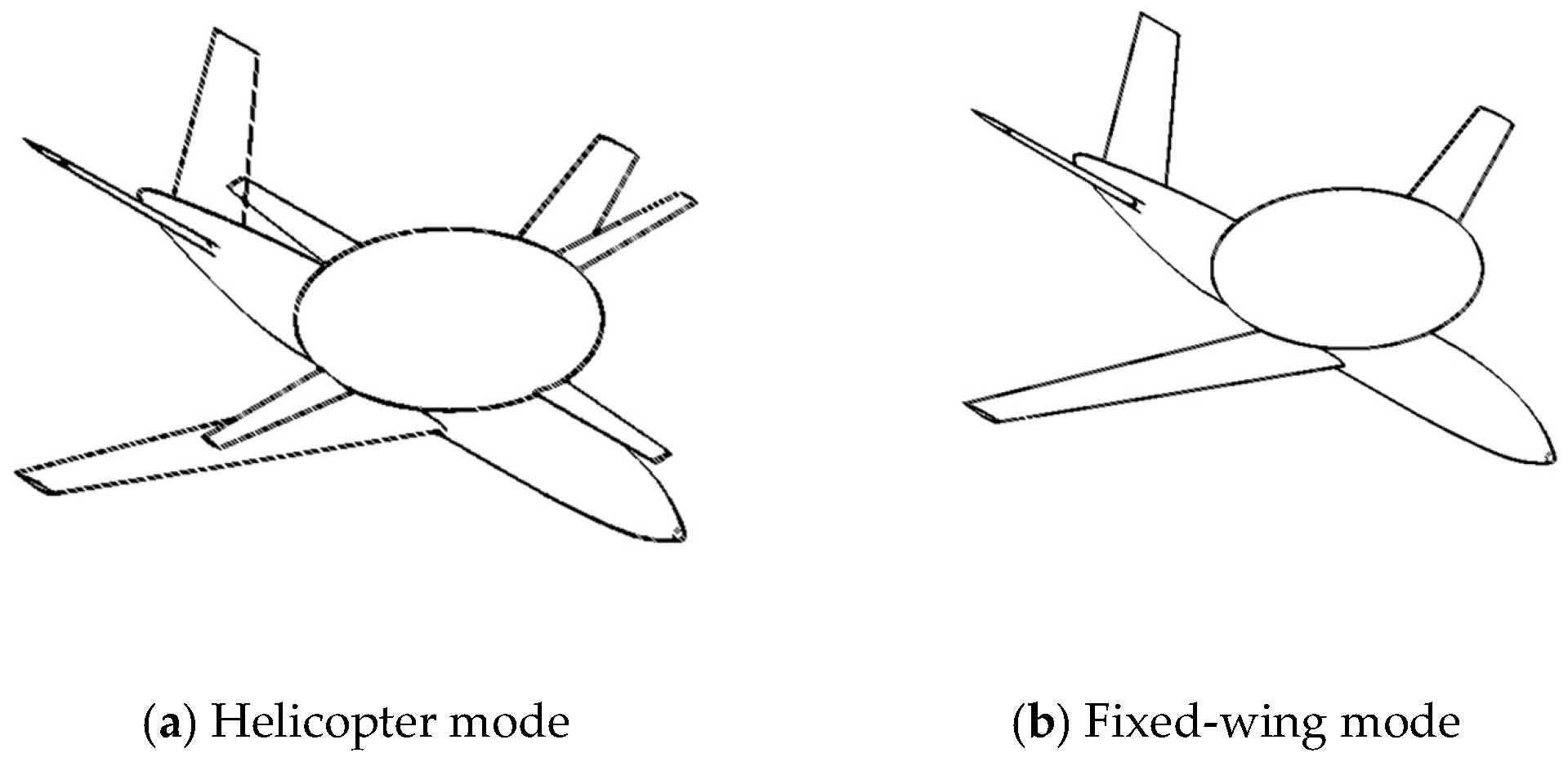
Consequently, the CRHA configuration emerges as a promising solution designed to maximize both rotor and fixed-wing efficiencies. In this design, the rotor extends during vertical takeoff/landing or hover phases, operating in a helicopter mode. Conversely, the rotor retracts during cruise flight, transforming the aircraft into a true fixed-wing configuration. Concepts exemplifying this approach include the Boeing-DARPA Disc-Wing/Fixed-Wing design [
10], Stroub’s M-85 concept [
11], the Modus morphing disc-rotor VTOL UAV [
12], and a collectible-rotor compound demonstrator [
13]. Both designs incorporate fixed wings, with their rotors housed within dorsal fairings (disks mounted atop the fuselage), and both utilize jet engines for propulsion.
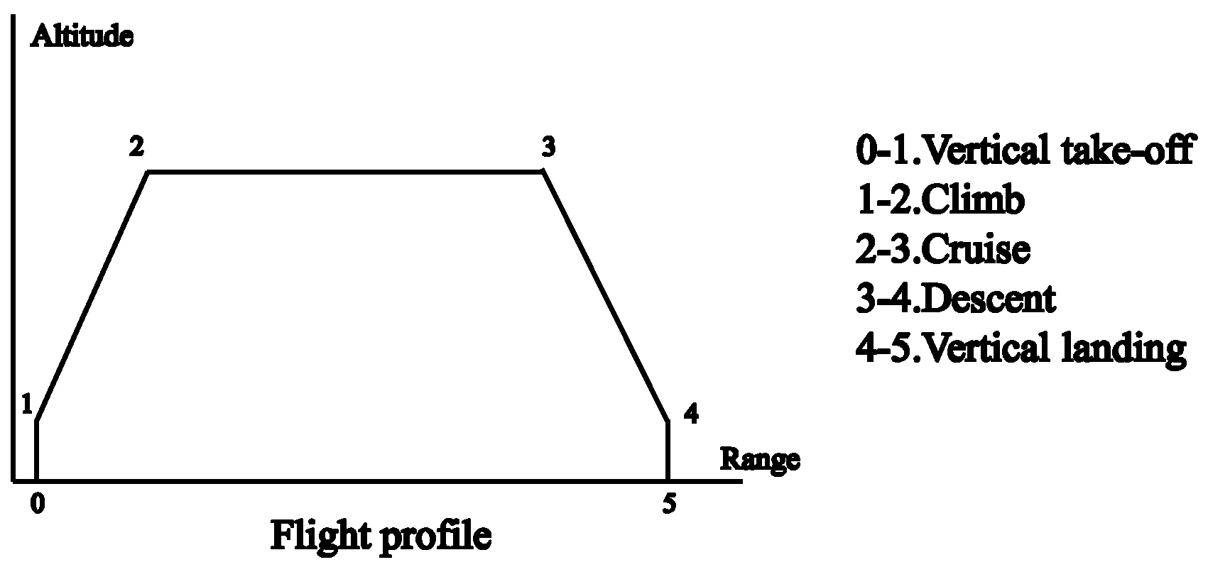
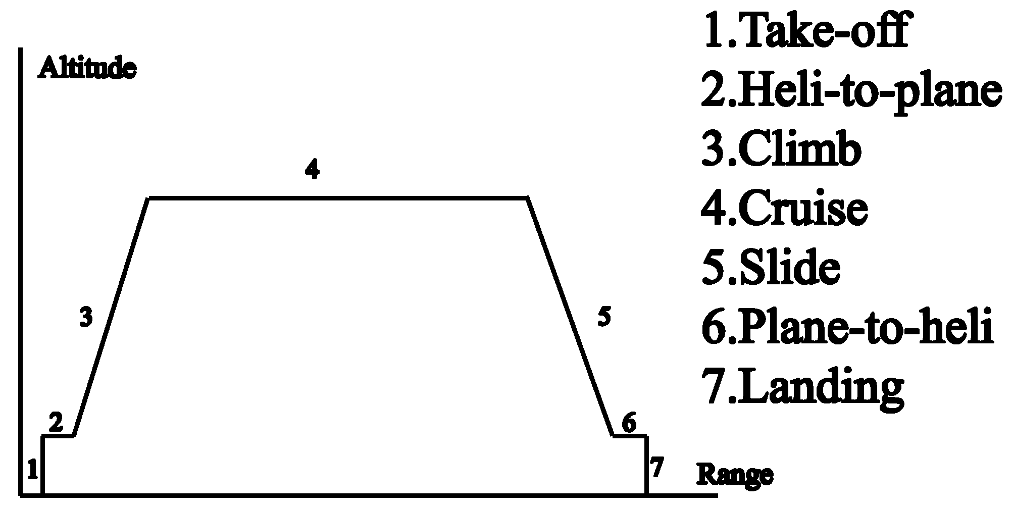
The CRHA possesses a highly unconventional mission profile, characterized by distinct flight phases: a pure helicopter mode for VTOL, a transition segment involving simultaneous operation of both rotor and fixed-wing systems, and a pure fixed-wing mode encompassing climb, descent, and cruise segments. Furthermore, it integrates critical components typical of both helicopter and fixed-wing aircraft configurations: the rotor system and drive train of a helicopter, combined with the wings, empennage, and propulsion system of a fixed-wing vehicle. This distinctive hybrid flight regime and inherently complex system architecture present unique challenges during the conceptual design phase. Specifically, the established weight estimation methodologies and selection processes for key design parameters used for conventional rotorcraft or fixed-wing aircraft cannot be directly applied to the CRHA configuration.
For conventional fixed wing aircraft and helicopters, the methods of MTOW estimation and parameter sizing at the conceptual design stage are well established, such as traditional empirical parametric methods [
14] and multi-objective optimization methods [
15,
16], as well as the Flight Optimization System method developed by the NASA Langley Research Center [
17] and the machine learning-based aircraft sizing method proposed by Vegh et al. at Stanford University [
18].
For VTOL aircraft, research has focused primarily on compound helicopters, tilt-rotor aircraft, and multi-rotor compound wing aircraft. Research in this area has focused primarily on compound helicopters, tilt-rotor aircraft, and multi-rotor compound wing aircraft. For compound helicopters, Tanabe et al. outlined an iterative design strategy. Initially, using empirical data on the empty and total weights of a helicopter, an estimate of the total weight was derived. This included the weights of the additional wings, engine, and propeller to determine the overall weight of the compound helicopter. This weight estimation subsequently informed the design and selection of parameters for the main rotor [
19]. Yeo proposed a methodology for the selection of the general parameters of a composite helicopter and conceptual design through the utilization of fitting functions. These functions were based on comprehensive data from extant research projects on compound helicopters conducted by NASA and the US Army, including but not limited to MTOW, cruising speed, disk loading, wing loading, and other parameters, where the fixed-wing drag and propeller hub drag used in the performance estimation were derived on the basis of historical data fitting [
20]. The aforementioned methods are applicable in the context of existing primary alignment aircraft. Russell and Johnson developed three conceptual designs for a helicopter, compound helicopter, and tilt-rotor aircraft that were all required to meet the same performance specifications and design requirements, where the wing and tail rotor design was to be a direct reference to a similar layout as the Cheyenne helicopter, while the wing and rotor design of the tilt-rotor mechanism was based on the Large Civil Tilt-Rotor (LCTR2) layout [
21]. The described methodology is analogous to the concept derived from existing methods.
For tilt-rotor aircraft, Kamal and Serrano developed a conceptual design for a tilt-rotor unmanned aerial vehicle, selecting key design parameters such as disk loading and wing loading based on the performance requirements of fixed-wing and rotor-wing aircraft, respectively [
22]. Cetinsoy et al. designed a small tilt-wing vehicle, with the key design parameters simply calculated from the mission requirements. These were then used to derive the wing aero foil shape and planform geometry [
23]. Zeng et al. undertook the conceptual design of a small electric tilt-rotor vehicle, identifying some parameters for consideration, including wingspan, mean chord length, taper ratio, fuselage width, fuselage height, rotor arm length, flight speed, etc. Furthermore, some constraints were constructed, including those pertaining to fuselage length, fuselage area, rotor arm length, and minimum speed. These constraints were established with the objective of maximizing the range and hovering time, and the quadratic sequence planning method was employed for parameter optimization [
24]. This method is applicable in instances where a preliminary aerodynamic scheme has already been established. Pedro et al. studied the design and performance quantification of four VTOL architectures for a canard-type aircraft. The aerodynamic modeling was conducted using the lift line method with several parameters, including the wing area, wing aspect ratio, and wing taper ratio [
25]. This method is also suitable for cases where a preliminary aerodynamic layout is available. To design a small electric multi-rotor composite wing aircraft (quadrotor + fixed-wing), Tyan et al. proposed a preliminary sizing integrated methodology [
26]. This approach defined the performance requirements as a set of functional relationships, derived empirical equations based on available data, and mainly considered VTOL and cruise mission. This approach essentially follows the traditional design iteration idea of determining the general parameters for the helicopter and fixed-wing modes.
In summary, although some integrated VTOL/fixed-wing sizing frameworks exist for compound, tilt-rotor, and eVTOL aircraft—typically based on available data, predefined layouts, or established empirical formulas—a conceptual-sizing methodology for CRHA has yet to be developed. Moreover, for an unconventional configuration like CRHA with a non-standard mission profile, the selection of key design parameters and the estimation of MTOW during the early design phase, prior to layout and sizing, represent one of the foremost challenges that designers need to address. However, existing methods lack an integrated approach that directly couples key design parameters with MTOW. Therefore, for CRHA, it is essential to develop an MTOW estimation model that comprehensively accounts for all three flight modes—helicopter, transition, and fixed-wing—while directly coupling key design parameters with MTOW. Such a model would enable rapid preliminary selection of key design parameters and initial estimation of MTOW.
This paper proposes a rapid conceptual design methodology for parameter sizing and gross weight estimation for CRHA (as illustrated in
Figure 1). First, component-based weight estimation models incorporating key design parameters (e.g., disk loading, power loading, wing loading) are established. Second, for building a full-profile fuel weight model, power-based fuel weight fraction calculations govern rotor-dependent phases (VTOL and transition), whereas fuel consumption during fixed-wing segments (climb, cruise, descent) adapts conventional fixed-wing fuel fractions by incorporating the aerodynamic impact of the retracted rotor housing. Third, integrating these weight models with specified mission payload mass, the framework establishes the minimization of MTOW as the primary objective. Seven key design parameters are used as design variables—three sizing parameters (wing loading, rotor disk loading, and power loading), one wing geometric parameter (aspect ratio), and three rotor-system parameters (number of rotor blades, rotor solidity, and tip speed). Optimization is executed via a hybrid strategy coupling GA for global exploration with SQP for local refinement. Finally, the validity of the empty weight model, fuel burn model, and integrated optimization logic was verified, supplemented by parametric sensitivity studies to assess key influences. The framework presented in this paper is designed to provide a methodology for sizing optimization and gross weight estimation during the conceptual design phase of CRHA configurations.
3. Weight Estimation and Initial Parameter Sizing
Based on the previously established weight models, this section formulates conceptual sizing as a constrained optimization problem. The MTOW is the quantity to be minimized and is determined implicitly through mass build-up and performance constraints.
3.1. Design Variables
The design vector includes seven independent variables for CRHA—three sizing parameters (wing loading
, rotor disk loading
, and power loading
), one wing geometric parameter (aspect ratio
A), and three rotor-system parameters (number of rotor blades
, rotor solidity
, and tip speed
):
Here, , , .
Accordingly, this section summarizes and classifies all parameters involved in the weight models into three categories: aircraft type-related parameters, performance indicator parameters, and design variables, as shown in
Table 7.
(1) Aircraft type-related parameters
The aircraft type-related parameters primarily reflect the fundamental characteristics of the designed configuration, aerodynamic layout, and propulsion system. This category encompasses empirical constants, structural form factors, and engine performance indices, which are mainly determined by the selected airframe configuration and engine type. For a given design task, these parameters are typically assigned fixed values based on engineering experience or reference aircraft data, ensuring the applicability and physical consistency of the weight models throughout the optimization process.
The aircraft studied herein is categorized as a twin-turboprop configuration, with corresponding helicopter-mode propulsion provided by turboshaft engines. Helicopters typically have relatively low safe hover altitudes, ranging from approximately 400 ft to 700 ft (120–210 m) [
48], with hover durations of about 20–30 s. For this CRHA design, the hover altitude h
hover is preliminarily set to 150 m. The maximum vertical ascent speed is taken as 10 m/s, while the descent speed is lower, set at 5 m/s.
The minimum level-flight speed for twin-turboprop aircraft typically ranges from about 130 to 150 kt (66–77 m/s) [
69]; here, a representative value of 70 m/s is selected. Additionally, the zero-lift drag coefficient
is approximately 0.02 for a clean propeller aircraft and 0.03 for a dirty, fixed-gear propeller aircraft [
14]; here, 0.02 is selected based on the type of research aircraft.
Engine PSFC is taken as 0.4 kg/kWh for helicopter and transition-flight modes and 0.3 kg/kWh for the fixed-wing cruise mode. Finally, the duration of the transition segments is set to 40 s, referencing typical tilt-rotor aircraft values. The specific values of these parameters used in this study are listed in
Table 8.
(2) Performance indicator parameters
The performance indicator parameters are primarily determined by the mission requirements and operational scenarios of the aircraft, encompassing variables such as cruise speed, flight altitude, mission duration, range, and payload capacity. These parameters directly reflect the performance standards that the aircraft must achieve for specific tasks, independent of the particular type or structural dimensions of the airframe. Performance indicators are typically specified by the design requirements or customer needs and serve as external inputs to the optimization model, exerting a significant influence on the overall design outcomes.
(3) Design variables
The design variables are directly related to the overall characteristics of the aircraft being developed. Each parameter has a significant impact on the dimensions and weight of the aircraft and must be determined at the outset of the preliminary design process.
Aspect ratio (A): Represents the ratio of the wing span to the chord, primarily influencing lift and aerodynamic efficiency in fixed-wing flight mode.
Power loading (): The weight supported per unit power, reflecting takeoff and hovering performance in helicopter mode as well as climb and acceleration capabilities in fixed-wing mode.
Wing loading (): The weight supported per unit wing area, mainly affecting takeoff and landing performance in fixed-wing mode.
Number of rotor blades (): Influences the structure and strength of the rotor system.
Disk loading (): The weight supported per unit rotor disk area, affecting the load-carrying capacity in helicopter mode.
Rotor solidity (): The ratio of total blade area to rotor disk area, determining the rotor’s ability to generate thrust.
Tip speed (): The linear velocity at the rotor blade tip, which affects the thrust in helicopter mode and constrains the maximum forward speed during transition flight.
These design variables comprehensively characterize the structural, aerodynamic, and propulsion features of CRHA at the conceptual design stage. They play a critical role in determining the maximum takeoff weight and performance indices and are highly adjustable and feasible in engineering practice. The optimization bounds for these variables are mainly based on empirical values from similar aircraft under specified performance requirements.
3.2. Optimization Problem Objective
The overall optimization model aims to minimize the MTOW by coupling subsystem weights, performance parameters, and design variables in a closed-loop formulation. The optimization problem is as follows:
where MTOW
is obtained implicitly by the mass build-up and performance feasibility.
3.3. Constraints
This section enforces feasibility during sizing/initial optimization via four groups of constraints: (i) mass build-up closure; (ii) fixed-wing mode: cruise power, climb gradient, stall speed; (iii) helicopter mode: vertical-climb power, hover power, rotor thrust-coefficient bounds; (iv) transition flight: transition power and tip-Mach.
3.3.1. Mass Build-Up
According to
Section 2.2, MTOW includes empty weight, fuel weight, and payload (empty weight and fuel weight implicit MTOW closure):
where
.
Equation (44) closes the weight recursion using the empty-weight and fuel-weight models established earlier.
is solved implicitly at each iterate of the optimizer. In the weight model, subsystem weights can be expressed as follows:
3.3.2. Fixed-Wing Mode
(1) Cruise power constraint
At the cruise segment, the shaft power required equals the propulsive power to overcome aerodynamic drag. The cruise power cannot exceed the maximum continuous power of the engine:
where
denotes the cruise power fraction (according to FAA training guidance, preliminary sizing typically assumes that cruise uses about 65–75% of the engine’s power [
70], so the upper limit of the cruise power fraction is set at 75%), and the cruise drag is modelled with a parabolic polar
together with the lift–weight equilibrium
L =
W, giving the following:
Combining the above with the definitions of power loading
and wing loading
, this constraint is equal to:
(2) Climb-gradient constraint
The required climb power can be decomposed into level-flight power plus the rate of potential energy increase:
where
is the climb power fraction. Similar to cruise, the climb power must be below the engine’s maximum continuous power; accordingly, the climb power fraction is taken the same upper bound as cruise,
. Vertical speed relates to the climb angle (small-angle) as follows:
For turboprop aircraft with MTOW between 5–8 t, the near-ground rate of climb typically ranges from 1500 to 1700 ft/min (e.g., DHC-6-400: 1600 ft/min [
71]; Do-228: 1570 ft/min [
72]; L-410 NG: 1673 ft/min [
73]). Taking
and using the initial speed in the climb segment
, the climb angle is 0.123 rad ≈ 7 degree (small-angle).
Using the parabolic drag polar together with the lift–weight equilibrium, the climb-power constraint can be written as follows:
As the actual climb speed may vary but shall not be lower than the terminal speed of the transition segment, a conservative form is as follows:
(3) Stall-speed constraint
In the fixed-wing flight segment, the minimum admissible speed is taken as the terminal speed of the transition segment. The stall speed must not exceed this minimum:
The maximum lift coefficient
is taken from typical ranges by aircraft class. According to
Airplane Design (Roskam), twin-propeller transports commonly have
. Considering that a configuration featuring a disk can yield a slightly higher achievable lift coefficient than a conventional layout [
63], a higher value of
is taken.
3.3.3. Helicopter Mode
(1)Vertical takeoff power constraint
The time of helicopter mode segments is short; therefore, the available shaft power is limited by the engine power rather than the maximum continuous power. The required power in vertical takeoff (Equation (20)) shall not exceed the engine power:
Hover and vertical landing power are not greater than the vertical takeoff requirement under the same conditions; therefore, no separate constraints are imposed for those cases.
(2) Thrust-coefficient constraint
According to
Basic Helicopter Aerodynamics (Seddon and Newman) [
65], the rotor thrust coefficient based on tip-speed dynamic pressure is as follows:
For characterizing the rotor operating point, the blade-loading coefficient
is more commonly used than
itself. The rotor thrust is therefore bounded via blade-loading within a typical range of 0.10–0.20 [
65].
3.3.4. Transition Mode
(1) Transition flight power constraint
Similar to helicopter mode, the time of transition mode segments are also short; therefore, the maximum power limit of the engine is used, rather than the maximum continuous power. The required power in the vertical-to-horizontal transition segment (Equation (31)) shall not exceed this limit.
(2) Tip-Mach constraint
Since no specific conversion-flight strategy is prescribed, an engineering bound is imposed by linearly superposing the rotor tip speed and the maximum forward speed at the end of conversion. The advancing-side tip Mach number is limited to 0.85:
where
is the local speed of sound.
3.3.5. Feasible Domains of Design Variables
To visualize the coupling among design variables, this section maps the constraints of the above three modes of fixed wing, helicopter, and transition into two design spaces:
(
Figure 7) and
(
Figure 8).
In
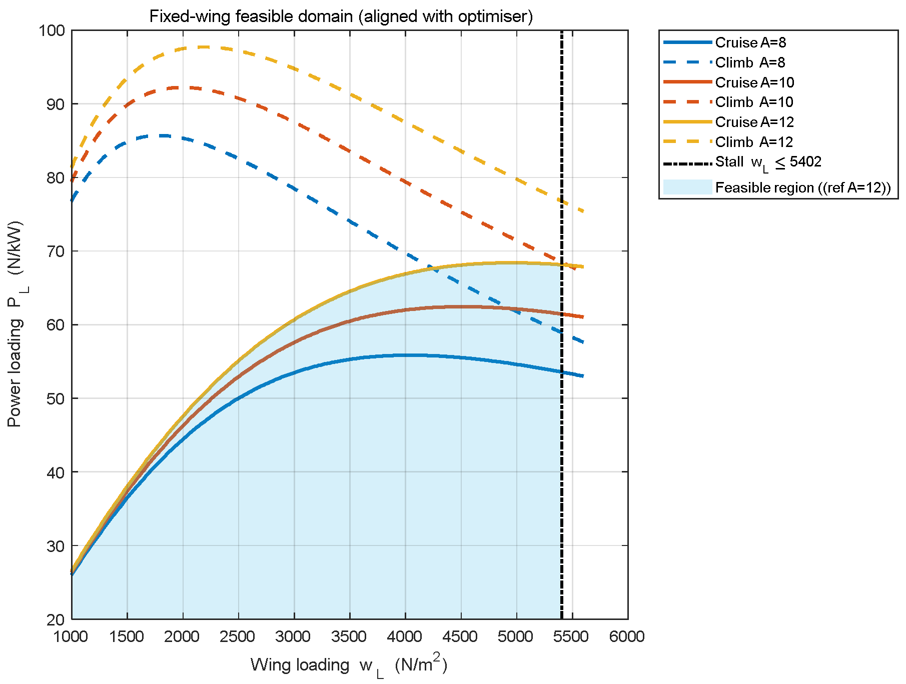
Figure 7, the cruise-power and climb-gradient constraints generate three upper boundary lines for aspect ratio
, and the feasible region is below them. The stall constraint adds a vertical line of
, the left of which is feasible. In the wing loading-power loading matrix, the blue shaded area is the feasible area.
In
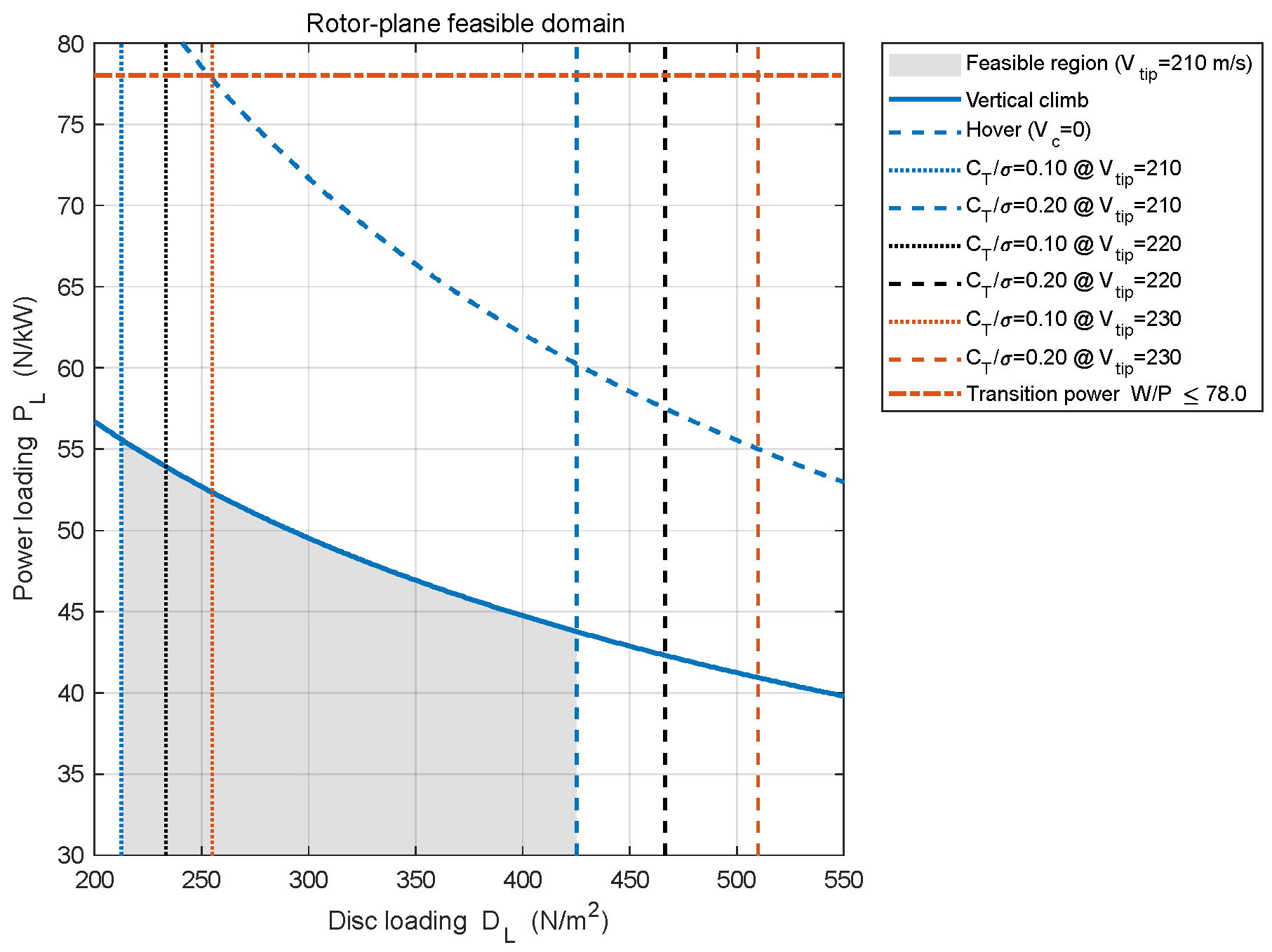
Figure 8, the vertical takeoff power constraint, together with the hover power, generates two upper-bound curves; the region below each curve is feasible. For each tip speed (
), the maximum and minimum blade-loading parameters
yield a pair of boundaries that are vertical to the disk loading axis; feasibility lies between the two lines. The transition-power constraint appears as a horizontal line (perpendicular to the power loading axis), with feasibility below it. In the disk loading-power loading matrix, the grey shaded area is the feasible area.
3.4. Optimization Method
The optimization problem in this study involves 7 design variables and 13 external input parameters (8 flight-type-related parameters and 5 performance metric parameters), resulting in a highly nonlinear model that is prone to multiple local optima. To obtain a reliable global optimum, a hybrid global–local optimization strategy is adopted. In particular, one design variable (number of rotor blades) is integer-valued and is handled via a minimal enumeration strategy. First, for each enumerated blade count, the GA performs a global search over the continuous design subspace to avoid being trapped in local minima. Subsequently, SQP is applied with
held fixed to refine the GA solution, thereby accelerating convergence and reducing computational cost. Across the enumerated subproblems, the feasible solution with the smallest
is selected.
Table 9 presents the selected optimization algorithm parameters, and
Figure 9 illustrates the overall structural framework of the conceptual parameter optimization method employed in this study. The GA provides good global exploration capability, robustness, and randomness, whereas the SQP algorithm offers rapid convergence. This hybrid optimization strategy combines the advantages of global search and efficient local convergence and has been widely used in aerospace parameter design, effectively improving the reliability and engineering applicability of the model solution.
5. Sensitivity Analysis
Sensitivity analysis quantifies the degree to which design variables affect subsystem weights and the overall MTOW. In this section, both local sensitivity analysis and Sobol-type global sensitivity analysis [
76] are employed to evaluate the impacts of design variables on system weights.
As the empty-weight and fuel-weight sub-models are explicit with respect to the design variables and, at the baseline, are independent of the optimization loop, we evaluate dimensionless, gradient-based local elasticities at the validated design point to verify signs and magnitudes. Conversely, MTOW is obtained implicitly by solving an optimization problem over the design space; hence, pointwise gradients alone may be misleading. We therefore treat local MTOW sensitivities as diagnostic (design-point) information while using Sobol first-order and total-effect indices over the admissible bounds to rank drivers and capture interactions.
5.1. Local Sensitivity Analysis of the System Weight Model
In this section, a local sensitivity analysis of the system weight is conducted using the design point identified during the optimization validation described in
Section 4.1 as the baseline. The analysis aims to quantify the relative influence of each design variable on empty weight, fuel weight, and MTOW in the immediate neighborhood of the design point. The elasticity metric is defined as
and is evaluated via central finite differences with ±1% perturbations of each continuous variable about the baseline (provided in
Table 16). In the empty-weight analysis,
is held constant to avoid artificial feedback through model terms that scale with gross weight. Integer variables (number of blades) are treated by ±1-blade finite differences and are not mixed with continuous-variable elasticities in the same plot.
MTOW is obtained implicitly from the closure
Therefore, its pointwise derivatives follow the implicit-function relation
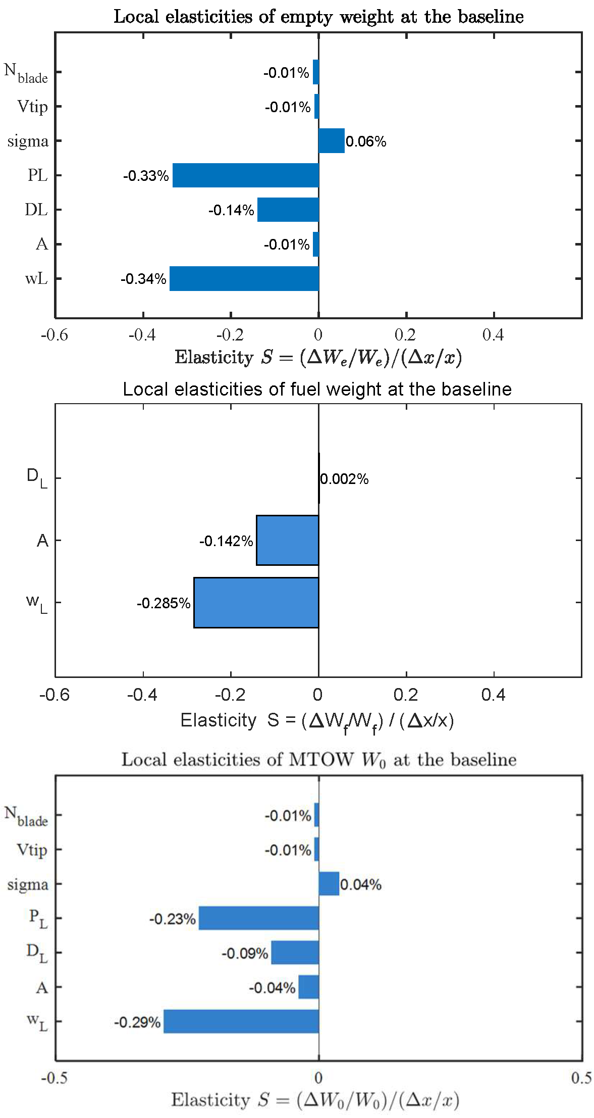
Figure 12 illustrates the local sensitivity of empty weight, fuel weight, and MTOW to each design variable.
The local elasticities at the baseline design point show that wing loading, power loading and disk loading exert the largest effects on operating empty weight. Wing loading appears negative (−0.34% per 1%) because higher wing loading reduces wing area and the structural mass of the wing/tail group. Power loading is negative (−0.33% per 1%) since higher power loading (more weight per unit installed power) implies lower rated power and reduced engine/installation mass. Increasing disk loading reduces rotor diameter and associated blade and hub masses, yielding a negative elasticity (−0.14% per 1%). Rotor solidity is positive (0.21% per 1%), as larger total blade area increases blade mass. Aspect ratio, solidity, tip speed and blade number have a small effect (less than 0.05% per 1%) because their structural contribution is largely captured indirectly through wing loading and disk loading instead of these four parameters.
The fuel-weight elasticities are dominated by wing loading and aspect ratio. Wing loading is strongly negative (−0.285% per 1%) because, in cruise-dominated missions, parasite drag prevails; increasing wing loading reduces wing area and drag, improving range fuel economy. Aspect ratio is also negative (−0.142% per 1%) via reduced induced drag; its smaller magnitude reflects the minor share of induced drag in the selected cruise condition. Disk loading shows a near-zero, slightly positive elasticity (0.002% per 1%) since its influence is concentrated in hover/transition segments, which occupy a small fraction of the overall mission energy budget.
The MTOW elasticities are consistent with a weighted combination of the empty-weight and fuel-weight effects at the baseline. Wing loading remains the single most influential driver (−0.29% per 1%), reflecting its sizeable empty-weight and fuel weight. Wing loading is similarly important and negative (−0.23% per 1%) owing to the sizeable empty weight leverage coupled. Disk loading is negative(-0.09% per 1%) through its empty-weight channels. Aspect ratio, solidity, tip speed and blades number are small influence(less than 0.05% per 1%). The local ordering at the baseline is therefore physically well-founded.
5.2. Global Sensitivity Analysis of MTOW
Global sensitivity analysis evaluates how variations in the input design variables across the entire design space affect the output parameter (MTOW). It not only assesses the effect of individual variables on the output but also captures interaction effects between variables.
In global sensitivity analysis, the first-order sensitivity index
(effect of single variable changes) and the total-effect sensitivity index
(considering both direct and interaction effects) can be defined as follows:
where:
Y represents the output (MTOW in this study);
Xi denotes the i-th design variable;
X∼i indicates all design variables except Xi;
E(Y∣Xi) is the conditional expectation of output Y given Xi;
Var(∼) denotes the variance operator.
The difference between the total-effect index and the first-order index reflects the interactions between the variables.
Here, the first-order sensitivity index
quantifies the contribution of the individual variable alone to the variance of the output, whereas the total-effect sensitivity index
captures the cumulative impact of the variable itself along with its interactions with other variables. The difference between these two indices represents the degree of interaction between the variable of interest and the other variables. The ranges of the design variables match those described previously in
Section 4.2.
The results of the global sensitivity analysis are summarized in
Table 17 below:
According to the Sobol sensitivity analysis results, wing loading is the dominant driver of MTOW (S1 = 0.5996, ST = 0.6387), followed by power loading (S1 = 0.3378, ST = 0.3799) and dick loading (S1 = 0.0143, ST = 0.0153). Aspect ratio and rotor solidity contribute modestly (S1 = 0.0015 and 0.0012), whereas tip speed and blade number are negligible. Comparing first-order and total-effect sensitivity indices reveals that the difference between their sums across all design variables is only approximately 10%, and the sum of first-order indices is 0.95. This indicates weak interactions among the design variables within the considered global design space. The ordering is consistent with the local sensitivity: variables with both sizeable gradients and wide ranges (wing and power loading) dominate, while those with large local gradients but narrow admissible ranges (e.g., solidity, tip speed) contribute little to global variance.
Combined with the results of local sensitivity and global sensitivity analysis, a CRHA fast parameter-selection scheme can be obtained. Bracket wing loading globally is first, since it shows the highest global sensitivity and a large local gradient at the design point. Next, we define the feasible region for wing loading, disk loading, and power loading according to the constraints, as disk loading and power loading rank immediately after wing loading in global sensitivity and also exhibit strong local gradients. Finally, we fine-tune rotor solidity and aspect ratio, as the admissible range is narrow but local gradient at the design point is high. Tip speed and blades number have minor influence and can be fixed at nominal values in conceptual sizing.
