Review

Review of Thrust Vectoring Technology Applications in Unmanned Aerial Vehicles

School of Technology, Beijing Forestry University, Beijing 100083, China
*
Author to whom correspondence should be addressed.
Drones 2025, 9(10), 689; https://doi.org/10.3390/drones9100689
Submission received: 19 July 2025 / Revised: 27 September 2025 / Accepted: 3 October 2025 / Published: 6 October 2025

Abstract

Thrust vectoring technology significantly improves the manoeuvrability and environmental adaptability of unmanned aerial vehicles by dynamically regulating the direction and magnitude of thrust. In this paper, the principles and applications of mechanical thrust vectoring technology, fluidic thrust vectoring technology and the distributed electric propulsion system are systematically reviewed. It is shown that the mechanical vector nozzle can achieve high-precision control but has structural burdens, the fluidic thrust vectoring technology improves the response speed through the design of no moving parts but is accompanied by the loss of thrust, and the distributed electric propulsion system improves the hovering efficiency compared with the traditional helicopter. Addressing multi-physics coupling and non-linear control challenges in unmanned aerial vehicles, this paper elucidates the disturbance compensation advantages of self-disturbance rejection control technology and the optimal path generation capabilities of an enhanced path planning algorithm. These two approaches offer complementary technical benefits: the former ensures stable flight attitude, while the latter optimises flight trajectory efficiency. Through case studies such as the Skate demonstrator, the practical value of these technologies in enhancing UAV manoeuvrability and adaptability is further demonstrated. However, thermal management in extreme environments, energy efficiency and lack of standards are still bottlenecks in engineering. In the future, breakthroughs in high-temperature-resistant materials and intelligent control architectures are needed to promote the development of UAVs towards ultra-autonomous operation. This paper provides a systematic reference for the theory and application of thrust vectoring technology.

1. Introduction

With the continuous maturation of UAV technology, especially in the wave of development of the low-altitude economy [1] in full swing [2], thrust vectoring technology has received increasing attention from researchers. Thrust vectoring technology, also known as vector propulsion technology, is a technology that achieves precise control of UAV attitude by adjusting the direction and magnitude of engine thrust [3]. Its core concept is to generate additional control torque by changing the direction of thrust to achieve flexible control of flight attitude [4].
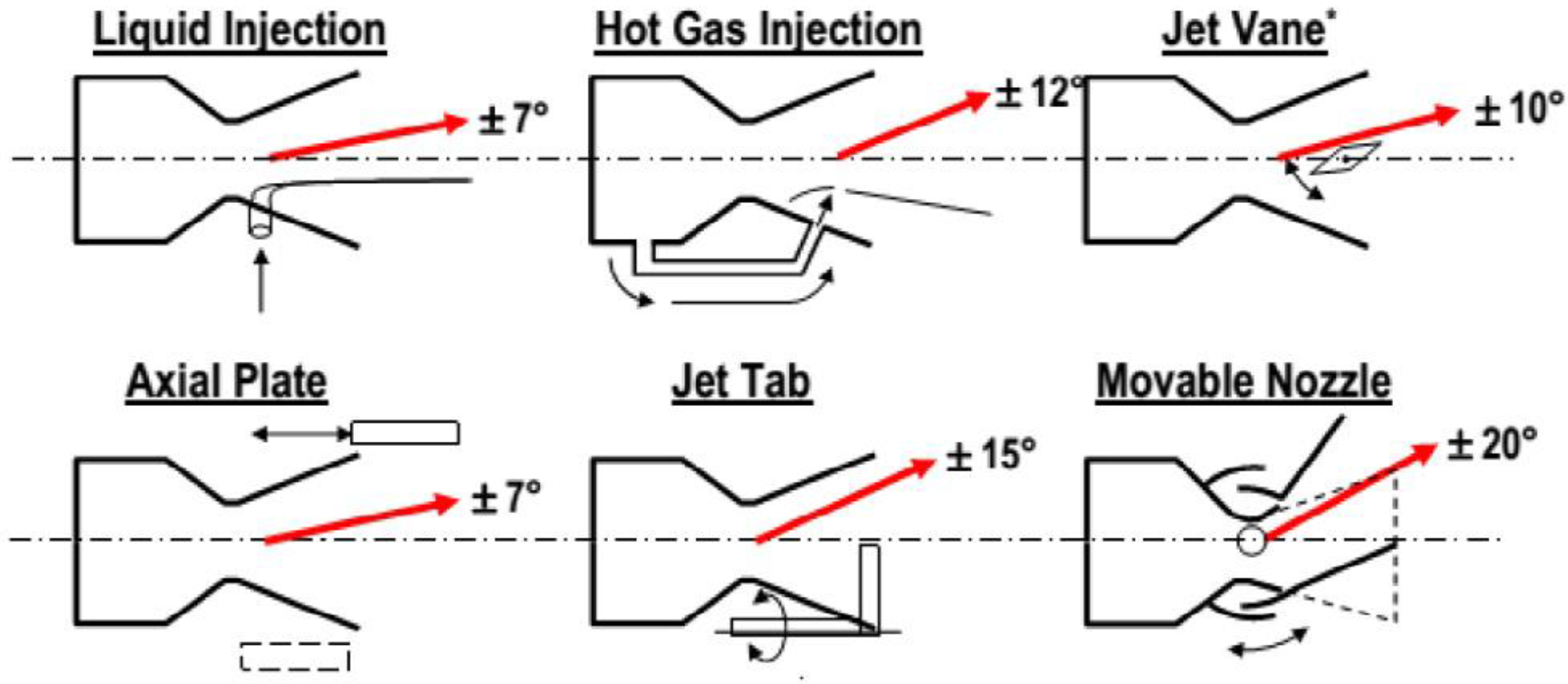
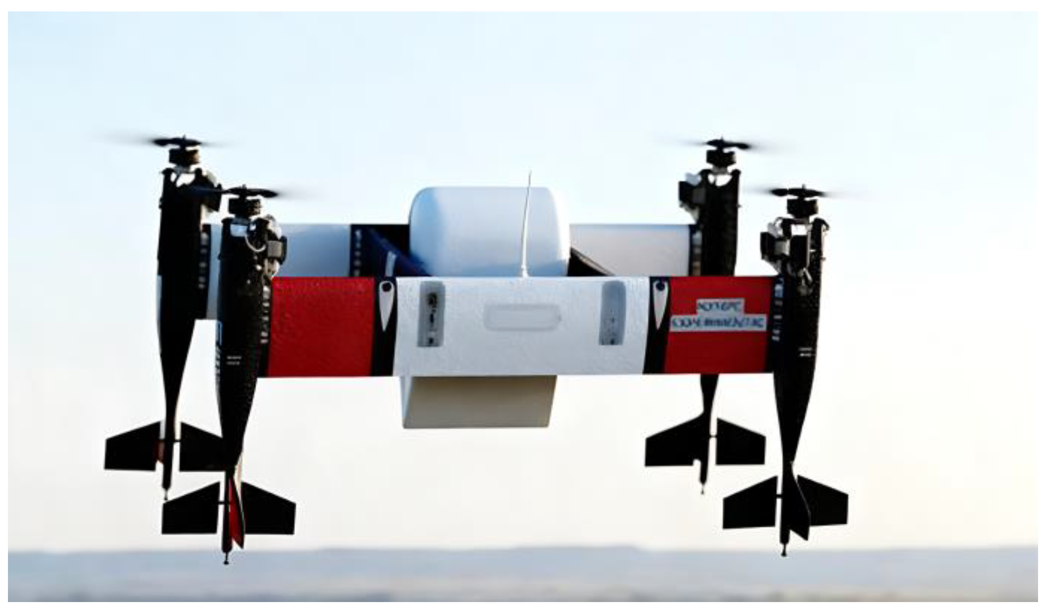
As shown in Figure 1, the current mainstream thrust vectoring technologies present three major technology routes. One of them is mechanical thrust vectoring technology, which achieves thrust direction adjustment through mechanical transmission (e.g., F-22 [5] adopts ± 20° axisymmetric deflection nozzle), and its deflection efficiency is even close to 100% [6], but the mass of the parts to achieve its related action accounts for up to 30% of the total engine mass [7], and there exists a certain structural burden [8], and the nozzle is subjected to complex forces, which places a high requirement on structural strength and stiffness [9]. Another important route is the fluidic thrust vectoring technology, the core of which lies in the use of hydrodynamic effects (Coandă effect, secondary flow injection) to change the direction of the jet [10] (e.g., Magma UAV [11]) and achieve vector regulation without moving parts, with a substantial increase in response speed compared to mechanical nozzles The same control effect is achieved with lower weight and cost [12], but there is also a loss of thrust (the thrust coefficient is generally between 0.86 and 0.94) [9]. The third route is a distributed electric propulsion system [13], which creates a synthetic thrust vector through motor swarm synergy [14], relying on, for example, independent multi-rotor speed control [15] (e.g., Textron’s MK4.8HQ [16]), which provides a 15% improvement in hovering efficiency over conventional helicopters [17] (XV-24 aircraft) and is particularly suited to vertical take-off and landing (VTOL) scenarios.
Despite the significant progress of thrust vectoring technology, the existing research still has the following three deficiencies: first, the system dynamics modelling for multi-physics coupling (aerodynamic-thrust-structural) is not yet perfect; second, a model reference adaptive control allocation strategy is lacking for complex tasks; and third, engineering solutions and reliability assessments for extreme environments (such as high dynamics and thermal loads) continue to present challenges. This paper analyses the principle, control and application of thrust vectoring technology by systematically combing through a large number of core works in the literature in the past decade, focusing on revealing the breakthrough progress of thrust vector systems in dynamic coupling inhibition and optimal energy management, etc., so as to provide theoretical support and technological foresight for the research and development of the next-generation intelligent unmanned aerial vehicle (UAV).

2. Fundamentals and Mathematical Models

2.1. Mechanical Thrust Vectoring Technology

Mechanical thrust vectoring is mainly a technique to change the thrust direction by physically deflecting the nozzle direction of the engine [18]. It can be classified into longitudinal and transverse lateral deflection in terms of deflection degrees of freedom. Longitudinal deflection (pitch direction) adjusts the direction of thrust in the vertical plane (e.g., UAV climb or dive); transverse lateral deflection (yaw/roll direction) adjusts the direction of thrust in the horizontal plane (e.g., UAV steering or roll) [19]. The relevant mathematical models are developed below [20]:
(1) 
Definition of a coordinate system
The analyses in this paper are all carried out in the airframe coordinate system, in which the origin is solidly attached to the centre of mass of the UAV, where the X b axis points forward along the longitudinal axis of the airframe, the Y b axis is perpendicular to the symmetry of the airframe to the right, the Z b axis is vertically downward, and the three form a right-handed right-angle coordinate system. The thrust vector is discretised as shown in Figure 2.
The UAV is subject to the following thrusts in the airframe coordinate system:
T = [ T x , T y , T z ] T = T total cos α T cos β T T total sin β T T total sin α T cos β T
where T x is the effective propulsive force, controlling forward flight speed; T y is the yaw moment, controlling heading; T z is the pitch moment, controlling climb or dive; α T is the longitudinal deflection angle, the angle of the thrust vector in the longitudinal plane of symmetry concerning the X b axis (positive upwards); and β T is the transverse lateral deflection angle, the angle of the thrust vector in the fuselage symmetry plane projected concerning the X b axis (positive to the right).
(2) 
Equations of motion for the centre of mass
Aerodynamic forces include drag D (opposite to airspeed), lift L (perpendicular to airspeed), lateral forces Y (perpendicular to airspeed and lift); and gravity G = [ G x , G y , G z ] T , which is the force of
G x = m g sin θ uav pitch G y = m g cos θ uav pitch sin ϕ uav roll G z = m y cos θ uav pitch cos ϕ uav roll
where θ uav pitch is the pitch angle, and ϕ uav roll is the roll angle.
In addition to the external forces applied, the rotation of the vehicle (angular velocity p , q , r ) leads to a change in the velocity component u , ν , w , which produces a Coriolis acceleration. Thus, the centre-of-mass acceleration equation is as follows:
m u ˙ v ˙ w ˙ = F e + F ic = T x D cos α cos β Y cos α sin β + L sin α + G x T y D sin β + Y cos β + G y T z D sin α cos β Y sin α sin β L cos α + G z + m v r w q w p u r u q v p
where F e is the combined force of thrust, aerodynamic forces (drag D , lift L , lateral forces Y ) and gravity; F ic is the additional inertial force caused by the rotation of the vehicle (angular velocity p , q , r ); α is the angle of approach; and β is the angle of lateral forces.
(3) 
Equations of rotation
The moments are first synthesised, and the thrust moment is obtained by cross-multiplying the nozzle position r T = [ x T , y T , z T ] T and the thrust vector:
M T = r T × T = y T T z z T T y z T T x x T T z x T T y y T T x
In addition, there are aerodynamic moments (roll moment L , pitch moment M , yaw moment N ). Therefore, the angular acceleration equation can be obtained:
I p ˙ q ˙ r ˙ + p q r × I p q r = L + M T x M + M T y N + M T z
where I is the inertia tensor: I = I x x I x y I x z I x y I y y I y z I x z I y z I z z . The UAV is usually assumed to be symmetric, and the non-diagonal term is zero ( I x y = I x z = I y z = 0 ).
(4) 
Model Simplification Explanation
The mechanical thrust vectoring dynamic model in this section is established as a simplified analytical model based on the following assumptions: First, the nozzle is treated as a rigid structure, neglecting thermal deformation from high-temperature gases and transmission clearances. Such factors may cause thrust vector angle deviations in operation. Second, aerodynamic forces and thrust are calculated via static matching, excluding dynamic coupling between nozzle wake and wing aerodynamics. Third, the UAV is assumed to be a symmetric rigid body, disregarding dynamic variations in inertia parameters and centre-of-mass displacement.

2.2. Fluidic Thrust Vectoring Technology

Fluidic thrust vectoring technology achieves thrust vectoring by injecting a secondary jet into the engine main jet and using fluidic effects (e.g., shock waves, shear layer interference) to change the direction of the main jet [21]. Its core feature is that there are no mechanical moving parts, and thrust deflection is achieved by fluid control (as shown in Figure 3) [22]. The following is its associated mathematical modelling (still following the airframe coordinate system) [23]:
(1) 
Equation of conservation of momentum
It is assumed that the main fluidic velocity vector V 1 = [ V 1 x , 0 , 0 ] T (along the X-axis) and the control fluidic velocity vector V 2 = [ V 2 x , V 2 y , V 2 z ] T are defined by the injection angles ϕ (horizontal deflection) and θ (vertical deflection):
V 2 x = V 2 cos θ cos ϕ V 2 y = V 2 cos θ sin ϕ V 2 z = V 2 sin θ
where θ is the vertical deflection angle, which controls the component V 2 z of the fluidic in the z direction and directly affects the pitching moment M T y . ϕ is the horizontal deflection angle, which controls the component V 2 y of the fluidic in the y direction and affects the yawing moment M T z .
The total momentum vector is synthesised from the main fluidic and the control fluidic: P total = m ˙ 1 V 1 + m ˙ 2 V 2 , unfolded into three-dimensional components:
P x = m ˙ 1 V 1 x + m ˙ 2 V 2 x P y = m ˙ 2 V 2 y P z = m ˙ 2 V 2 z
(2) 
Thrust and moment generation
Thrust deflection angle (pitch θ thrust - pitch and yaw ψ thrust yaw ):
θ thrust - pitch = arctan P z P x , ψ thrust - yaw = arctan P y P x
Total thrust magnitude:
T = P x 2 + P y 2 + P z 2
If the position vector of the injection point of the control fluidic is r j = [ x j , y j , z j ] T , then the moment produced by the thrust is
M T = r j × T = y j T z z j T y z j T x x j T z x j T y y j T x
where T = [ T x , T y , T z ] T is the thrust vector, T x = P x , T y = P y , T z = P z .
(3) 
Equations of motion for the centre of mass
The centre of mass motion follows Newton’s second law, but because the airframe coordinate system is a rotating reference system, the time derivative of the velocity needs to incorporate an inertial coupling term. The equations take the form:
m u ˙ v ˙ w ˙ = T x D cos α cos β Y cos α sin β + L sin α + G x T y D sin β + Y cos β + G y T z D sin α cos β Y sin α sin β L cos α + G z + m v r w q w p u r u q v p
Drag D , lift L , and lateral forces Y are all aerodynamic.
(4) 
Equations of rotation
The rotation of the fuselage around the centre of mass follows the Eulerian equations of dynamics and requires consideration of gyroscopic moments. The equations are of the form:
I p ˙ q ˙ r ˙ + p q r × I p q r = L + M T x M + M T y N + M T z
where M T x , M T y , M T z is the thrust moment component.
(5) 
Model Simplification Explanation
The fluidic thrust vectoring dynamic model in this section is constructed as a simplified analytical framework based on the following assumptions: First, the jet is treated as an ideal incompressible fluid, excluding shock waves, vortices, and unsteady wall effects. Second, energy dissipation from viscous forces is neglected, and the flow field is assumed to be laminar; thrust fluctuations from turbulent pulsations are not considered. Third, synergistic effects between nozzle orifices and dynamic variations in deflection angle are not accounted for.

2.3. Multi-Rotor UAV Vector Models

Although multi-rotor vehicles do not directly employ vector nozzles, they achieve flight control in three dimensions by independently controlling the rotational speed and direction of each rotor [24], which is likewise an application of thrust vectoring technology.
(1) 
Rotor numbering and position definition (symmetrical cross configuration):
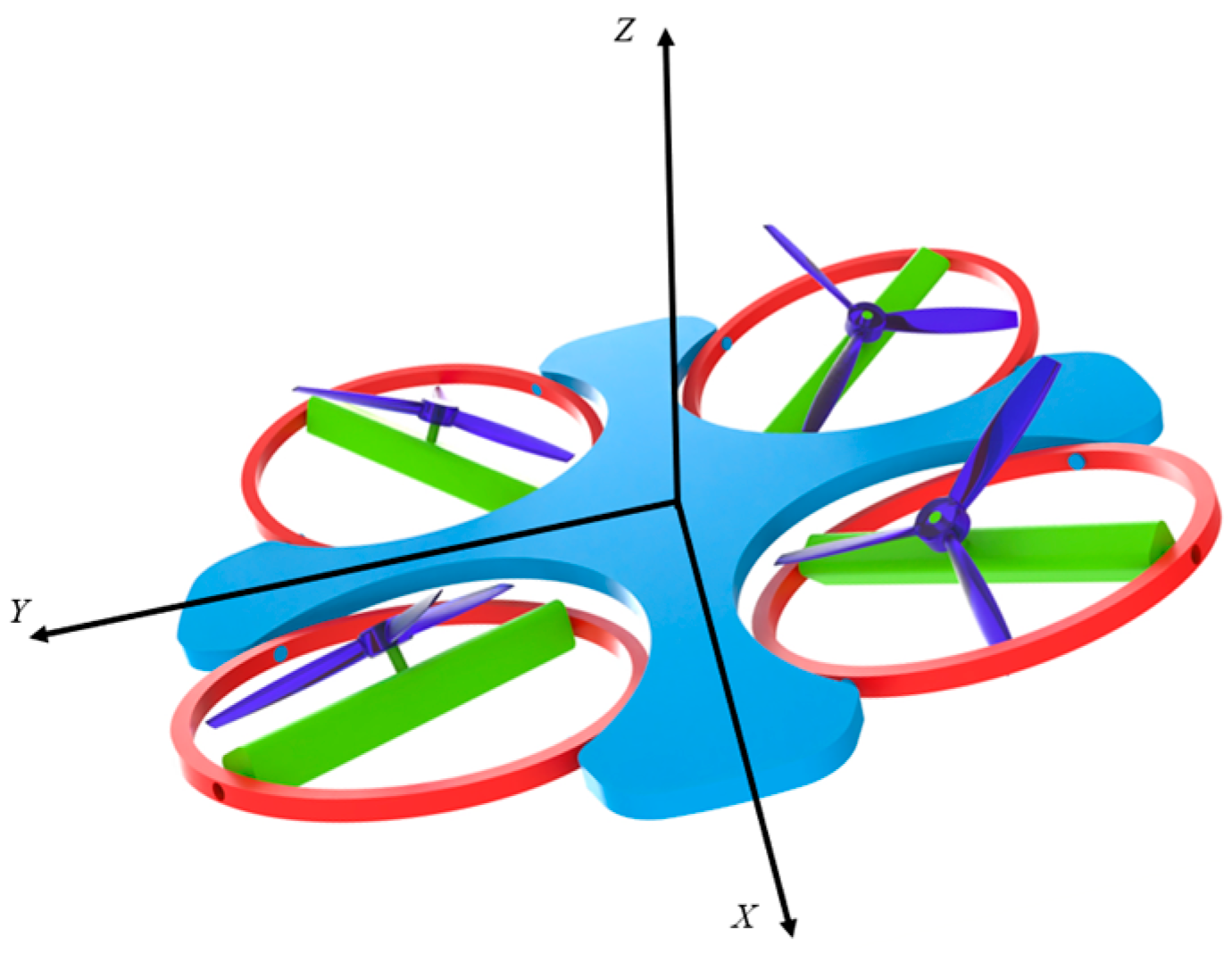
As shown in Figure 4, the vector model of the quadrotor UAV is taken as an example. The positions of rotor 1 (right front), rotor 2 (left front), rotor 3 (left rear), and rotor 4 (right rear) are
r rotor 1 = [ L arm , L arm , 0 ] T r rotor 2 = [ L arm , L arm , 0 ] T r rotor 3 = [ L arm , L arm , 0 ] T r rotor 4 = [ L arm , L arm , 0 ] T
where L arm is the rotor arm length.
(2) 
Rotor thrust vector:
The thrust direction of each rotor is defined by the polar angle θ r o t o r p o l a r i (pitch) and azimuth ψ rotor azim i (yaw):
T rotor i = T rotor i sin θ r o t o r p o l a r i cos ψ rotor azim i sin θ r o t o r p o l a r i sin ψ rotor azim i cos θ r o t o r p o l a r i , i = 1 , 2 , 3 , 4
where T i is the magnitude of rotor thrust, proportional to the rotational speed squared: T rotor i = k F ω i 2
(3) 
dynamical equation
The advection equation (Newton’s equation) of the total external force is the sum of the thrust and gravity of each rotor:
m x ¨ y ¨ z ¨ = i = 1 4 T rotor i m g e z + F aero
where F aero is the aerodynamic force (e.g., drag), usually modelled as a quadratic function of velocity.
The total moment in the rotation equation consists of the moment generated by the cross-multiplication of the thrust vector with the rotor position, the rotor counter-torque term, and other aerodynamic moments:
I p ˙ q ˙ r ˙ + p q r × I p q r = i = 1 4 r i × T rotor i + M aero
where M aero is the aerodynamic moment (e.g., gyroscopic effect, inter-rotor interference moment).
(4) 
Model Simplification Explanation
The multi-rotor thrust vectoring model in this section is established as a simplified analytical model based on the following assumptions: First, each rotor is assumed to operate independently, disregarding aerodynamic interference between rotors and ground effects. Second, a linear thrust–rotor speed relationship is adopted, neglecting thrust decay at high angles of attack and motor delay. Third, gyroscopic torques from rotor rotation and airframe aerodynamic damping are not accounted for.

3. Key Technology Systems

3.1. Vector Realisation Technique

The technological realisation paths of UAV thrust vectoring systems show significant differentiation, and their core design needs to satisfy the dynamic balance between thrust deflection efficiency and system complexity [25]:
η s = δ F δ J
The geometric vector angle ( δ J ) is the physical angle at which the vector nozzle is deflected, the angle at which the nozzle structure is deflected away from the engine axis; the thrust vector angle ( δ F ) is the angle between the actual thrust direction and the engine axis after the nozzle is deflected [26].

3.1.1. Mechanical Vector System

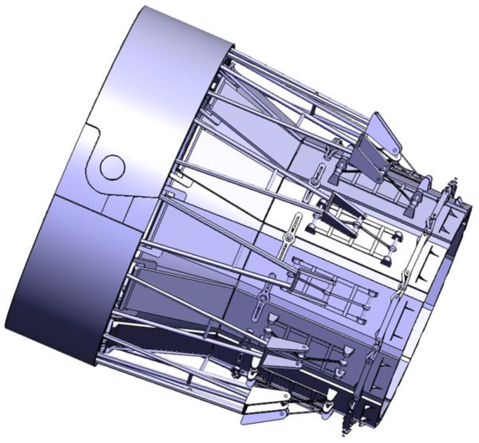
Shown in Figure 5 is a mechanical vectoring system based on a precision transmission mechanism for thrust direction regulation by axisymmetric nozzle deflection [27], the technical features of which include the following [28]:
(1) The true vector angle of the drive mechanism with spherical hinges is significantly affected by the flow field asymmetry.
(2) The nozzle movable body outlet convergence half angle has a significant effect on the performance.
(3) The shape of the inner flow path is directly related to the total pressure recovery coefficient.
(4) The trade-off between vector angle requirement and thrust loss needs to be combined with the overall requirements.
In the case of the MiG Skate demonstrator [29], for example, its RD-5000B engine is equipped with a three-dimensional thrust-vectoring nozzle, which brings significant advantages in several aspects. First, it significantly enhances the attitude control capability of the aircraft, and the three-dimensional thrust vectoring nozzle realises the pitch and yaw control, which reduces the reliance on the traditional wing rudder. Second, it effectively optimises the stealth performance of the whole aircraft, and the tailless flying wing layout combined with thrust vectoring technology avoids the radar reflection of the traditional drogue and rudder. Third, it embodies the superiority of system integration, with the electronic control system of the RD-5000B engine deeply integrated with the all-digital flight control system of the MiG-29OVT demonstrator, improving flight stability and response speed. Finally, the RD-5000B provides a strong guarantee in terms of power efficiency. Although the RD-5000B has a ‘no charge chamber’, the thrust vectoring nozzle optimises the propulsive efficiency through precise airflow deflection, which enables the Skate to achieve a maximum low-altitude flight speed of 800 km/h, a ceiling of 12,000 m, an altitude of 3000 m and a combat radius of 2000 km. The RD-5000B is also equipped with a thrust vectoring nozzle.
Current designs and analyses of mechanical vector nozzles predominantly focus on combat aircraft applications. Their structural characteristics, where moving components account for up to 30% of the engine’s total mass, pose adaptation challenges for small unmanned aerial vehicles with low payload redundancy. To extend this technology to small UAVs, structural weight must be reduced by simplifying spherical hinge transmission mechanisms and employing lightweight materials such as shape memory alloys. Concurrently, the high cost and extended maintenance cycles inherent in mechanical vector nozzles conflict with commercial UAV requirements for economic efficiency and low maintenance. Subsequent designs must therefore balance thrust control precision against cost and weight constraints.

3.1.2. Fluidic Vector System

As shown in Figure 6, the fluidic effect-based fluidic vectoring technology changes the main fluidic trajectory through secondary flow injection [30]: for example, the reverse flow control technology induces a reverse secondary flow by forming a negative pressure cavity between the outer casing and the main nozzle, and when the outflow velocity is 0.3 Ma, only 1~2% of the secondary flow pumping volume is needed to achieve a maximum thrust vectoring angle of 14~16°. With Coanda effect-based isotropic flow control technology through tangential high-speed secondary flow injection, every 1% of the mainstream flow of the secondary flow can produce 1.8~2.4° continuous vector deflection, and the thrust coefficient is as high as 0.98. Passive control of the wedge-shaped multi-control orifice nozzle in low-speed conditions shows good continuous control characteristics: when the valve closure is increased from 60% to 80%, the vector angle increases linearly from 4° to 14°, and the maximum deflection angle reaches 14°. In the process of wall attachment, the shear layer vortices merge to form a separation bubble, and the inverted outflow is discharged, while the outflow is sucked in through the control holes when the fluidic is away from the wall, resulting in the rupture of the separation bubble. In the wing coupling experiments, the downward deflection of the fluidic by 12° can increase the lift-to-drag ratio by 24% at 2° headway angle, extend the stall headway angle from 22° to 23°, and increase the maximum lift coefficient by 22% [31].
A delta-wing UAV [32] using this technology employs co-flow fluid thrust vectoring (co-flow FTV) to achieve pitch control through primary and secondary airflow synergy. The maximum 27° deflection was achieved by primary (19 m/s) and secondary (40 m/s) dual fluidic flows. The dynamic model transfer function pole (−13 ± 82.84 i) verifies the system stability, and the root trajectory PID controller enables a pitch response time of 0.485 s. The FTV technology avoids mechanical parts, reduces weight and radar signals, and is suitable for high-altitude and low-dynamic-pressure environments.
Figure 6. Common approach schemes for thrust vectoring techniques [33].
Drones 09 00689 g006

3.1.3. Distributed Electric Propulsion System

As illustrated in Figure 7, the Distributed Electric Propulsion (DEP) system comprises multiple propellers or fans distributed across the wings or fuselage, driven by electric motors to provide the aircraft’s primary thrust [34]. This configuration overcomes the performance limitations inherent in traditional centralised propulsion systems, offering a novel platform for the efficient application of thrust vectoring technology. It has demonstrated significant advantages in enhancing aerodynamic efficiency, optimising take-off and landing performance, and strengthening system redundancy. Consequently, it has become a key propulsion solution for small short take-off and landing (STOL) unmanned aerial vehicles (UAVs) and electric vertical take-off and landing (eVTOL) aircraft [35].
The DEP system, leveraging the thrust direction adjustability and distributed layout of its multiple propulsion units, effectively achieves vector thrust functionality. Its core configurations primarily comprise two types: tilt-rotor vector thrust and differential vector thrust. Regarding tilt-rotor vector thrust, this configuration designs some or all DEP propulsion units as tilt-rotor structures, altering thrust vector direction by adjusting the tilt angle of the propulsion units. For instance, a certain DEP STOL unmanned aerial vehicle [36] employs eight tiltable propellers distributed along the wing leading edge. During take-off and landing phases, the propellers tilt vertically downward or at a steep angle to generate lift. In cruise mode, they tilt horizontally forward to provide thrust, enabling seamless transition between vertical lift and horizontal propulsion. Differential vector propulsion leverages the distributed layout of multiple propulsion units within DEP systems. By adjusting the magnitude or direction of thrust across different zones, it generates vectoring torque for attitude control. For instance, an eight-rotor DEP UAV employing this technology [37] achieves roll control through thrust differentials between left and right propulsion units, pitch control via thrust differentials between front and rear units, and yaw control through thrust differentials between diagonal units. The entire process operates without reliance on conventional control surfaces, significantly simplifying the control architecture.
A detailed comparison of the three thrust vectoring technologies is presented in Table 1.

3.2. Control Theory and Methods

UAV thrust vector systems face strong nonlinear control challenges under multi-source perturbations [38], and control architectures with strong robustness need to be constructed [39]:
x ˙ = f x + g x u + d t y = h x
where x R n is the state vector, f x is a nonlinear dynamic function of the system, g x u is a control input term, d t is a composite perturbation, and d t D max (the perturbation is bounded) [40].

3.2.1. Active Disturbance Rejection Control (ADRC)

ADRC achieves real-time estimation and compensation of perturbations using a third-order expanded state observer (ESO), whose core algorithm [41] contains
Tracking differentiator (TD) [42]:
v 1 k + 1 = v 1 k + T v 2 k v 2 k + 1 = v 2 k + T f h a n v 1 k r k , v 2 k , r , v 0
Nonlinear state error feedback (NLSEF):
u 0 = β 1 f a l e 1 , α 1 , δ + β 2 f a l e 2 , α 2 , δ
Junjie Liu’s team [43] proposed a high angle of attack decoupling control strategy based on linear self-resistant control, which achieves strong coupling perturbation suppression by designing three-channel independent controllers (pitch angle, sideslip angle, and roll angle rate). The study adopts a six-degree-of-freedom nonlinear model (with 12 state variables) combined with a thrust vector model to compensate for the aerodynamic rudder deficiencies, in which the thrust nozzle deflection range is limited to ±20°. In the simulation verification, after setting up the initial conditions, the Herbst manoeuvre simulation shows that the angle of attack is tracked to 62.5°, the roll angle rate response is stable, the heading angle is successfully flipped by 180°, the turning diameter is about 150 m, and the thrust vector deflection angle does not exceed the saturation limit, which verifies the validity of the control allocation strategy.
However, the convergence speed and accuracy of the traditional Linear Expanded State Observer (LESO) is limited by the bandwidth parameter tuning and does not explicitly handle the actuator constraints. For this reason, the team of Pengfei Li [44] made further innovations in active disturbance rejection control by proposing a super manoeuvre flight control strategy based on a predefined time-expanded state observer (PTESO), replacing the LESO with the PTESO and designing cascaded active disturbance rejection control with the control Lyapunov function and Lyapunov optimal control allocation algorithms. The PTESO can be used to achieve the maximum error of the heading angle of the actuator in a predefined period of time. Within the preset time, PTESO can make the estimation error converge, and achieve the maximum errors of head-on angle 15.0281°, side-slip angle 1.6563°, and roll angle 5.7544°, which are better than those of LESO.

3.2.2. Model Reference Adaptive Control (MRAC)

The vertical take-off and landing control of a thrust vector UAV has challenges such as strong nonlinearity, attitude–altitude coupling, and sensitivity to external perturbations, and early research focused on the design of basic control algorithms. The tail-seat UAV [45] developed by Kuang Minchi’s team [46] has a length of 1.5 m, a wingspan of 0.96 m, and a weight of 4 kg and adopts a single-channel fan engine (main thrust) and two auxiliary power motors. During the test, the vertical pitch and roll angles were stabilised near 0°, the vertical yaw angle was locked to near 170°, the maximum deflection range of the thrust vector nozzle was up to ±17°, and the absolute value of the altitude control error was less than 3 cm·s−1, which verified the effectiveness of the attitude and altitude control method.
However the robustness of the base controller to sudden perturbations (e.g., thruster failure, sudden mass change) is insufficient. For this reason Andres Perez [47] et al. proposed a model reference adaptive control strategy based on feedback linearisation and an artificial immunity system, which is designed to model the reference adaptive enhancement layer. When the simulated thruster power is unexpectedly reduced to 40% or an additional 130 g of mass is added, the performance of the base controller is severely degraded or even fails, while the immune-inspired adaptive layer can be quickly activated to compensate. In the thruster failure simulation, its global performance index (PI) reaches 86%, far exceeding the 0.6% of the base control; in the hardware-in-the-loop test, the model reference adaptive control achieves a performance improvement of more than 50% over that of the conventional PID, and the system shows a stable capability in the presence of system disturbances and uncertainties.

3.2.3. Backstepping Control

Backstepping control has been continuously developed and applied in the field of aircraft control due to the advantages of its systematic design approach in dealing with nonlinear systems. Bingqian Li et al. [48] designed an inverse step fault-tolerant control strategy based on a cascade observer, using parameters such as state gain matrix L = diag ( 8 , 9 , 9 ) and adaptive learning rate matrix Γ = diag ( 1 , 2 , 3 ) . Under the simulation conditions of flight altitude of 4000 m and speed of 150 m/s, the uncertainty and rudder faults are effectively compensated, so that the attitude angle tracking error is less than that of general controllers, and rapidly converges to the vicinity of zero. The rudder deflection angle is within the permissible range and changes smoothly; the fault identification curve is highly consistent with the actual situation, accurately identifying 80% of the aileron faults at t = 2 s, 60% of the elevator actuator damage faults at t = 3 s, and the rudder actuator jamming faults at t = 6.5 s; the system is always running stably, and the global robust fault-tolerant control of the unmanned thrust vectoring aircraft is realised under the complex fault conditions.
To further improve the performance of backstepping control in handling complex nonlinear dynamics and suppressing the effects of high-frequency dynamics, as well as effectively responding to environmental disturbances, Ding Han [49] et al. designed a command-filtered backstepping controller by introducing a command filtering technique based on backstepping and applied it to the control of stratospheric airships. The controller can set the three Cartesian positions (x, y, z) and yaw angle of the blimp to desired values and stabilise the pitch and roll angles. Through simulation experiments, it maintains trajectory tracking despite wind field disturbances, verifying the effectiveness of the command filtering technique to enhance the robustness and anti-jamming of the backstepping controller, and the good adaptability of the multi-vector thrust allocation mechanism to the strongly nonlinear airship dynamics model.

3.2.4. Sliding Mode Control (SMC)

The core objective of sliding mode variable structure control in UAV attitude control is to solve the system uncertainty and actuator constraints by enhancing robustness. The finite time sliding mode controller (FTSMC) proposed by Longlong Chen’s team [50] for a co-axial tilt-rotor UAV proves the stability through the Liapunov theory and achieves co-axial UAV attitude tracking with a pitch angle rise time of 0.15~0.4 s and stabilisation time of 0.6 s and yaw angle rise time of 0.2~0.3 s and stabilisation time of 0.8 s in simulation on the Matlab/SimMechanics platform, and the maximum overshoot is controlled within 20% and 30%, respectively, which is better than with PID control, especially under external disturbance.
However, the traditional FTSMC still has limitations when facing time-varying parameters and actuator saturation constraints. To address this challenge, Benshan Liu et al. [51] proposed a fixed-time non-singular fast terminal sliding-mode control method and applied it to a one-dimensional thrust-vectoring turbojet vertical take-off and landing vehicle with uncertainty and input saturation. They integrated an anti-saturation auxiliary system into the sliding mode framework to deal with the external wind disturbances of the saturated turbojet thrust, designed the sliding mode surface combined with an adaptive law to estimate the time-varying mass and rotational moment of inertia uncertainties on-line, and finally demonstrated the superiority by proving that the state of the closed-loop system converged to the zero-neighbourhood within the fixed-time upper bound through stability simulation analysis. Furthermore, integrating the artificial potential field (APF) into sliding surface design, combined with time-synchronous stability characteristics, enhances control efficiency and reduces energy consumption without increasing computational burden. This is achieved by incorporating an inertia matrix into the sliding surface and employing a norm-normalised sign function. This design [52] demonstrates significant advantages in addressing time-varying constraints and system uncertainties, offering novel insights for the application of sliding mode control in unmanned aerial vehicles within complex scenarios.
The distinctive features and trade-offs of the different control methods are summarized in Table 2.

3.3. Path Planning Algorithm

UAV path planning needs to achieve multi-objective optimisation under satisfying dynamics constraints [57]. Based on this, Thi Thuy Ngan Duong et al. [58] constructed a mathematical representation of the multi-objective optimisation model and constraints:
min J = ω 1 F 1 + ω 2 F 2 + ω 3 F 3 + ω 4 F 4 s . t . | γ climb | γ climb max , | γ turn | γ turn max , v min v speed v max , z min z z max , d obstacle R obs + ϵ
where F 1 is the path length function, F 2 is the obstacle avoidance function, F 3 is the flight altitude function, F 4 is the path smoothness function, ω i is the weight coefficient, γ climb is the angle of climb, γ turn is the angle of turn, v speed is the speed, z is the altitude, d obstacle is the distance to the obstacle, and R obs is the radius of the obstacle.

3.3.1. Algorithms Based on Graph Search

(1) 
Improvement of the A* algorithm
Hu Mingzhe et al. [59] proposed an improved heuristic function method for the problems of poor real-time and large computational volume of the traditional A* algorithm in UAV 3D path planning by adjusting the weight factor and introducing an exponential factor to optimise the evaluation function. The final simulation results prove that the improved algorithm improves the search efficiency.
f ( k ) = g ( k ) + h i ( k ) h i ( k ) = w heuristic h ( k ) λ heuristic
where h i ( k ) denotes the improved heuristic function; w heuristic denotes the weight coefficient of the heuristic function; λ heuristic is the exponential coefficient of the heuristic function.
Qu Hongwei et al. [60] proposed an improved A* algorithm for the safety of UAV path planning in a base station environment, introducing an obstacle distance penalty term and dynamic weights to optimise the evaluation function and combining with a continuous detection strategy to eliminate redundant path points. Through experimental verification (Table 3), it significantly improves the path safety and navigation efficiency.
It is noteworthy that recent research has significantly enhanced path planning efficiency in complex environments by optimising the weighting mechanism of the A* algorithm. For instance, Zhang et al. [61] employed a strategy of dynamically adjusting the actual cost G ( n ) and the heuristic function weight H ( n ) in high-risk scenarios such as radiation fields within nuclear facilities:
F ( n ) = 1 + r R × G ( n ) + H ( n )
where r denotes the Euclidean distance from the current point to the endpoint, and R represents the distance from the starting point to the endpoint.
It successfully balances path search directionality with low-dose objectives. Experiments demonstrate that the algorithm reduces the number of executed points by 57.18% and shortens computation time by 13.79%, while maintaining an optimal cumulative path dose. This mechanism holds reference value for real-time path planning of unmanned aerial vehicles in environments with strong interference.
(2) 
Spatio-temporal Dijkstra algorithm
Aiming at the limitation that the traditional Dijkstra algorithm can only output a single shortest path and cannot deal with the conflict of multi-UAV collaborative tasks, the improved Dijkstra algorithm proposed by Huang Yihu [62] et al. records all the predecessor nodes of each node through variable-length backtracking arrays in multivariate human–robot collaborative path planning, detects the conflict combined with the time-window model, and prioritises the execution of high-priority tasks. When the paths and nodes of different tasks are in conflict, the conflicting nodes are set as temporary obstacles, and the paths are re-planned, which ultimately ensures that the paths of all tasks are conflict-free. After software verification, the improved algorithm significantly improves the planning efficiency of task collection, breaking through the limitation of the classical algorithm, which can only output a single shortest path.

3.3.2. Bionics-Inspired Algorithm

(1) 
Chaotic Particle Swarm Optimisation
Aiming at the problem that the traditional particle swarm optimisation algorithm tends to fall into the local optimum and has insufficient convergence accuracy in the complex 3D UAV path planning problem, it has been proposed to introduce chaos theory to improve the algorithm and to generate sequences with traversal and stochasticity by using Zaslavskii chaotic mapping [63] to replace the stochastic parameter in the traditional particle swarm algorithm in the speed updating formula, in order to enhance the global search capability and the ability to jump out of local optimums. The particle velocity update formula is improved as follows
v i d k + 1 = ω v i d k + c 1 r 1 x p b e s t x i d k + c 2 r 2 x g b e s t x i d k
where r 1 , r 2 is generated by a chaotic sequence.
The chaotic particle swarm algorithm proposed by Geng Zengxian et al. [63] uses Zaslavskii chaotic sequences to generate random numbers, constructs fitness functions for economic efficiency, flight altitude and obstacle avoidance, and sets the starting point (423 m, 23.5 m), the end point (165.5 m, 399 m), the number of particles (50), and the number of iterations (150), and the weights in path planning for UAVs in a region of Tianjin. With a flight altitude range of 40 m to 120 m, upper speed limit of 130 km/h, and penalty coefficient, the simulation results show that the algorithm outperforms the traditional PSO algorithm in terms of optimal path fitness value (140.398), iteration number (1136), resultant success rate (80%), and the mean of fitness function (149.731), and achieves efficient and accurate three-dimensional path planning for urban UAVs.
(2) 
Adaptive Ant Colony Algorithm
In order to solve the problem of slow convergence and premature maturity caused by the fixed pheromone updating mechanism of traditional ant colony algorithms in UAV path planning in complex environments, a study has been conducted in [54] to propose an adaptive ant colony algorithm, with the core design of designing a pheromone dynamic updating strategy [64]:
τ i j ( t + 1 ) = ( 1 ρ ) τ i j ( t ) + k = 1 m Δ τ i j k ( t )
where ρ is the pheromone volatility coefficient ( 0 < ρ < 1 ), and k = 1 m Δ τ i j k ( t ) is the sum of pheromone increments of all ants on path (i, j).
Kunyang Li et al. [65] used an optimised ant colony algorithm to plan UAV LiDAR routes in a vegetation zone application. Compared with the classical algorithm, the optimised algorithm iterates faster and converges better, and in vector environments 1 to 5, the first stable iteration time is shortened by 1000.915 s, 1397.168 s, 730.586 s, 348.262 s, and 114.330 s, respectively; the length of the planned routes is shortened by about 10% on average; the route nodes are covered by a lower degree of vegetation, and the theoretical ground-point density increased by 132.24% year-on-year, significantly improving the efficiency of ground point acquisition.

3.3.3. Integration of Related Technologies

(1) 
A*-PSO convergence architecture
Guo Kun et al. [66] address the need for high success rates of unmanned aerial vehicle (UAV) breakout missions in complex battlefield environments by generating discrete paths through the A* algorithm under multi-threat constraints, combined with inertial weight adaptive particle swarm optimisation (weight range 0.4–0.9) to optimise the trajectories. The simulation results show that compared with the RRT* and PSO algorithms, the path length is reduced by 13.2% and 18.8%, the average radar detection probability is reduced by 46.1% and 55.4%, the running time is reduced by 78.2% and 71.3%, and the success rate is 100%.
(2) 
ABC-RRT*
Niresh Jayarajan et al. [67] significantly improved the performance of 3D path planning for UAVs by fusing the global exploration capability of the Artificial Bee Colony (ABC) algorithm with the path optimisation features of the Rapid Exploration Random Treestar (RRT) algorithm. Experiments show that in 3D complex obstacle environments, the algorithm’s path length is shortened by 4.6% (urban box-shaped obstacle environments) and 9.3% (spherical obstacle-intensive take-off scenarios), the number of convergence iterations is reduced by 88.9% and 84.6%, the simulation time is optimised by 63.1% and 32.4%, and the standard deviation is as low as 0.0571, significantly outperforming that of IABC (0.1086). By balancing the exploration and exploitation mechanisms, ABC-RRT* achieves fast shortest path generation (convergence within 10 iterations) in dynamic environments, providing a highly stable and low-computational-complexity solution for real-time UAV obstacle avoidance.
A comprehensive comparison of the different path planning algorithms is presented in Table 4.

4. Typical Application Case Study

4.1. Applications in the Field of Drones

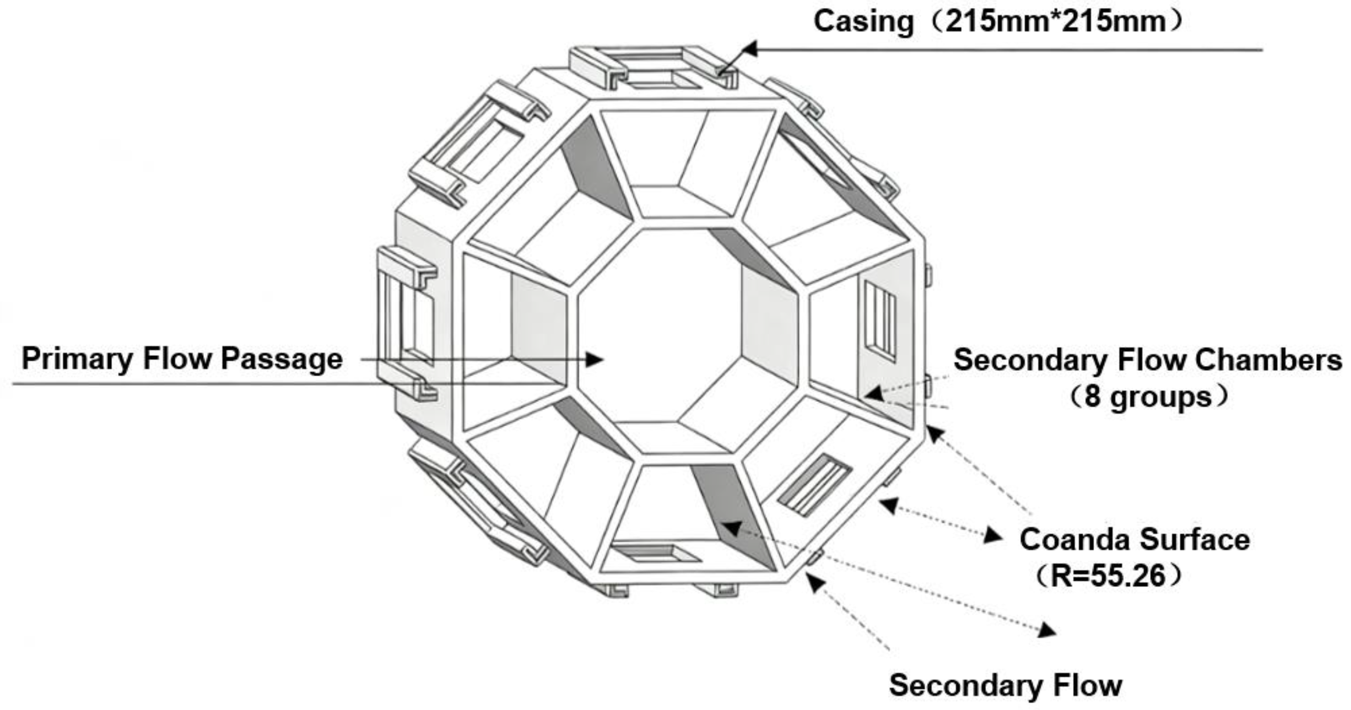
Ma Zhenqiang et al. [72] designed an omnidirectional thrust-vectoring six-rotor UAV (shown in Figure 8), which adopts a tiltable co-axial bi-rotor plus conventional quad-rotor design, with the outer quad-rotor used to stabilise the attitude, and the intermediate co-axial bi-rotor used to enhance the manoeuvrability. Combining the dynamic model with PID control, simulation results indicate that the drone with a mass of 1.2625 kg and a rotor arm length of 0.642 m can take off smoothly from its origin and maintain stable hovering at the (10,10,10) m position. In constant-speed flight mode, it can reliably sustain a velocity of 20 m/s with rapid convergence of attitude angle tracking error and minimal attitude fluctuation. This breakthrough overcomes traditional thrust–attitude coupling limitations, rendering it suitable for high-speed, high-manoeuvrability missions. As shown in Figure 9, Yao Qinghe et al. [73] designed a high-speed airflow thrust vector nozzle based on the Condor effect to achieve mainstream deflection control in eight directions. They investigated the influence of different parameters on the mainstream deflection effect through simulation, optimised the performance of the nozzle, and provided a new solution for thrust vector control of high-speed UAVs. Numerical simulations indicate that at a main flow velocity of 50 m/s, with only one air chamber open and a Kanda wall curvature of 55.46, the nozzle achieves a maximum deflection angle of 85.91° in the main flow. At a main flow velocity of 130 m/s, with three air chambers open and a curvature of 55.26, the deflection angle is 40.62°. The root locus PID controller reduces the pitch response time to 0.485 s.
In 2023, Martinez et al. [74] proposed a multi-rotor UAV add-on thrust vectoring system with three-degree-of-freedom culvert motors to achieve torque augmentation (up to 10.78 N-m), which supports three modes of switching: conventional flight, translational and torque. Experimental results show that in direct rotation mode, with 35% thrust, i.e., 3.7 N-m, the on/off valve can be actuated with a response time of 0.38 ms. Moreover, due to its tapered guidance design, ±35 mm tolerance self-alignment can be achieved, and the decoupled design of thrust and attitude reduces the control complexity, which confirms the effectiveness of the fast valve operation in high-altitude hazardous environments. The system’s positional control accuracy in translation mode falls within a tolerance of ±35 mm, with a response time of 0.38 ms capable of accommodating rapid operations at elevated heights.

4.2. Vertical Take-Off and Landing Vehicle Applications

In 2022, Yu Zelong et al. [75] proposed a thrust vector control method based on backstepping sliding mode control for the attitude stabilisation and tracking accuracy of a vertically take-off and landing-capable tilt-rotor stealth UAV in complex environments. The method decouples the attitude and trajectory by increasing the rotor control authority, improves the system response speed, and provides strong support for complex missions such as shipboard reconnaissance. Simulation testing validated the quantitative performance of this control method: under simulated conditions of flight altitude 4000 m and velocity 150 m/s, the attitude angle tracking error of the UAV was reduced compared to conventional controllers. Control surface deflection varied smoothly within permissible limits, exhibiting gradual transitions without abrupt fluctuations. System response speed surpassed that of traditional control strategies, enabling rapid compensation for disturbances and uncertainties in complex environments.
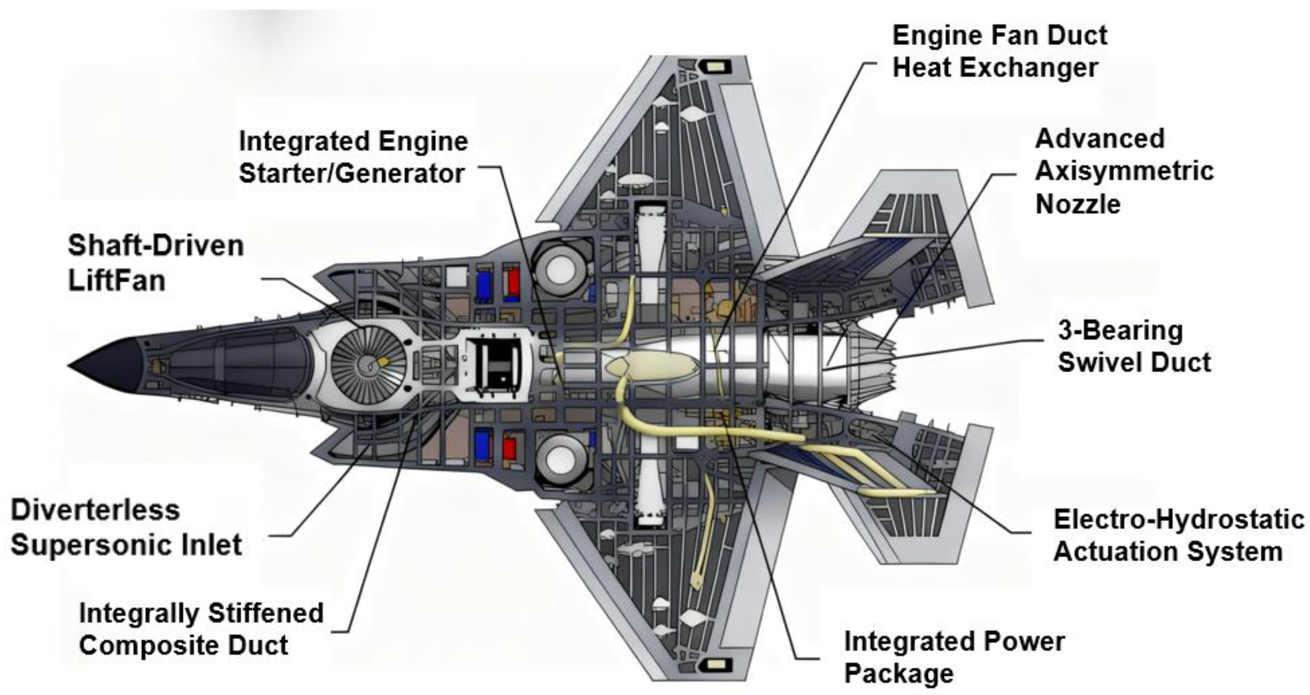
The mature application of vertical take-off and landing technology in manned aircraft provides critical technical references and engineering validation paradigms for unmanned aerial vehicles, particularly large heavy-lift or carrier-based VTOL UAVs. Taking the F-35B fighter jet illustrated in Figure 10 as an example, its coordinated design of thrust vectoring and lift systems exhibits high technical homogeneity with UAV VTOL scenarios in aspects such as power distribution and attitude control logic. This serves as a vital reference for the development of relevant UAV systems. The F-35B fighter [76] aircraft employs a short take-off and vertical landing (STOVL) configuration utilising an axially driven lift fan (79 kN) in conjunction with a three-bearing thrust vectoring nozzle (79 kN). The roll control nozzle provides 16.5 kN of thrust, yielding a total vertical lift of 174.5 kN. The three-bearing thrust vectoring nozzle exhibits a maximum pitch deflection of 95° and yaw deflection of ±12.25°. Vector thrust increases linearly with rising pressure ratio. The nozzle operating temperature exceeds 1000 K. However, the use of this high temperature gas will cause significant thermal load on the deck, and its system mechanical complexity is high. This technical challenge is equally present in the deck adaptation scenarios for carrier-based VTOL unmanned aerial vehicles. The F-35B’s thermal protection design, adaptive capabilities [77], and experience in structural lightweighting offer direct solutions to analogous issues in unmanned aerial vehicles. Future work should focus on adapting these technical principles to the size and payload requirements of unmanned aerial vehicles.
Beyond the typical applications of the aforementioned F-35B fighter aircraft, the innovative application of VTOL technology in novel unmanned aircraft configurations also holds significant engineering value. The tailless thrust-vectoring flying wing VTOL UAV [79] employs a dual thrust-vectoring flying wing configuration, dispensing with conventional control surfaces and achieving mode transitions through whole-aircraft tilt. Its multi-body dynamic model captures the non-minimum phase characteristics induced by the vectoring mechanisms. Combining Nonlinear Model Predictive Control with Incremental Nonlinear Dynamic Inverse in a cascaded control scheme, it achieved a smooth transition within 2.5 s during flight testing, with attitude tracking error below 1°. A distributed-propulsion wing-induced wing configuration VTOL UAV, utilising 12 embedded propulsion units on each wing, adjusts thrust direction via induced wing deflection. Digital simulations demonstrate safe boundaries of 0.6 g forward acceleration and −0.4 g reverse deceleration, with a maximum speed of 35 m/s [80]. For carrier-based maritime surveillance, a blended wing-body configuration VTOL UAV integrates low-drag characteristics with quadcopter VTOL capability. Fin-shaped landing gear enhances directional static stability derivatives by 30.1%. Following optimisation of airfoil and negative wing twist angle (−5°), the maximum lift-to-drag ratio reached 19.522, with endurance exceeding 10 h and a payload capacity of 15 kg [81]. These case studies provide practical references for VTOL configuration design and control optimisation across diverse mission profiles.

4.3. Speciality Robotics

Vector propulsion technology also has important applications in the field of specialised robotics. For example, a vertical climbing robot based on reverse propulsion technology [82] generates reverse adsorption force (for overcoming gravity) with a total thrust of up to about 86 N through four sets of ducted fan motors. It combines two brushless motors with a thrust of up to about 20 N to achieve wall navigation. The robot is designed with an aluminium body and has a total weight of 7 kg. It has the load capacity to perform multi-tasks and multi-attitudes and is suitable for high-rise buildings, spherical surfaces or various curved-surface operations. However, due to the design of brushless motors plus ducted fan motors, it is dependent on a high current supply, and the system needs to be further optimised for energy management efficiency or improved power usage.
Thrust vectoring technology is also widely used in bionic flight systems [83], which can be used to achieve specialised work. For example, a bionic flapping wing vehicle system [84] based on thrust vector micro-deflection technology achieves composite flutter (40% thrust increase) through an asymmetric wing skeleton (100% lift increase) with a vector drive. It adopts a flexible flutter layout (class 4 wind resistance, 5.5~7.9 m/s) with thrust vector regulation, combined with a bionic deformed tail (82% yaw moment reduction), and wind resistance is increased to class 5 (8.0~10.7 m/s). The system has an endurance of 30 min and integrates 35 g-class MEMS flight control (attitude error < 0.5°), which is suitable for environmental monitoring and pipeline inspection, while the long endurance (>6 h) under extreme turbulence still requires the support of a high-energy-density battery.

5. Technical Challenges and Limitations

Thrust vectoring technology faces multiple technical bottlenecks in engineering applications [85]. First, under extreme environmental conditions such as high temperature [86], high pressure [87] and high dynamics, the requirements for workpiece materials and thermal management [88] are relatively harsh [89]. For example, during the operation of the tail end of the SpaceX starship, the maximum heat flow density can reach 856 kW/m2, which is difficult to be sustained by traditional metal materials, and it is necessary to optimise the design of heat-resistant tiles with a heat-resistance upper limit of 1650 °C and stainless steel, in order to prevent structural failures under extreme thermal coupling environments [90]. Second are multi-physics coupling and nonlinear control challenges [91]: eVTOL/DEP vehicles have significant aerodynamic-vortex coupling under turbulence and high angle of attack ( α = 90 ° ). This is particularly pronounced in distributed electric propulsion systems. On the one hand, the aerodynamic interference effects in multi-rotor configurations are significant [92], the downstream thrust of tandem propellers decreases by 80% due to wake interference, and the standard deviation of lateral side-by-side propeller force fluctuations increases by 50%. Whilst the counter-rotation of adjacent advancing blade elements may partially offset torque and gyroscopic forces, it remains difficult to entirely circumvent the dynamic instability arising from airflow interactions between rotor blades. Its counterpart, the viscous vortex particle model (VPM), has a high accuracy (5–10% error), but its computational cost is two orders of magnitude higher compared to the semi-prescriptive vortex model (PVW).The PVW (with 10–15% error) is suitable for early-stage designs, but more efficient algorithms are still needed for extreme turbulence. [93] On the other hand, synchronous motor control presents bottlenecks [94]. Under a distributed layout, each propulsion wing assembly must independently respond to throttle and deflection commands. When confronted with wind speed disturbances or load variations, discrepancies readily arise between motor rotational speed and thrust output.
Energy efficiency and economics constrain scale-up applications [95]. The secondary flow energy consumption problem significantly affects range capability, the thrust vector angle is highly sensitive to the position of the fluidic (with a sensitivity index of 0.89), and the thrust loss is exacerbated by the elevated Mach number of the outflow under transonic conditions [96]. Distributed electric propulsion systems require the distribution of electrical power among multiple propulsion units [97]. From the perspective of energy allocation efficiency, when the aircraft is in a transitional flight mode, thrust requirements undergo dynamic changes, making it prone to energy distribution imbalances. In addition, manufacturing costs and airspace regulatory differences constitute major barriers—digital twin technology, while shortening the R&D cycle [98], requires huge investments (the global market size is expected to surge from USD 10.25 billion in 2022 to USD 269.1 billion in 2032) [99], while the EU EASA requires a manned eVTOL critical system failure probability of less than 10−9, a significant difference from China’s lenient CAAC standards for cargo models [100], forcing companies to customise their designs for different markets and increasing the cost of duplicate certifications by more than 23% [101]. Future techno-economic breakthroughs need to be achieved through the use of smart materials [102] (e.g., shape memory alloy nozzle weight reduction) and model reference adaptive control algorithms in concert with international standards.

6. Conclusions

This study systematically combed through many research results in the field of vector propulsion technology in recent years, revealing three major breakthroughs: at the level of control theory, algorithms such as active disturbance rejection control offer a greater improvement in accuracy than traditional PID control, and the multi-algorithm fusion strategy greatly improves the anti-wind disturbance capability, greatly shortens the response time, and conquers the problem of the dynamic coupling of the thrust-aerodynamic-structural problems. With the vector realisation technology, the efficiency of jet vectors has been improved based on the Coandă effect, and the mass load has been reduced. The F-35B demonstration aircraft, through its hybrid vector system, achieved a reduction in landing attitude error, marking the progression of the technology into a highly integrated stage. Through intelligent planning, the improved A*-PSO algorithm was applied to improve the efficiency of path planning for complex environments, and the spatio-temporal Dijkstra algorithm achieves close to 100% multi-machine co-operative obstacle avoidance, laying the foundation for cluster operation. These breakthroughs have established a technical framework for dynamic coupling inhibition, energy optimisation and intelligent decision-making, promoting the evolution of UAVs towards high mobility and high autonomy and providing a theoretical paradigm and technical reserve for the research and development of sixth-generation intelligent aircraft.
Facing the future needs of urban air traffic control and battlefield surprise defence, thrust vectoring technology needs to break through three major bottlenecks: first, the development of 1600 °C-resistant vectoring nozzle material and the reduction of the mass ratio of the actuator system through the simulation of thermal-force-electrical multi-field coupling; second, the construction of a brain-like intelligent control architecture and the realisation of high-frequency control based on a pulsed neural network and neuromorphic chip; and third, the adoption of optimised path planning algorithms and the compression of the large-area planning time into seconds.

Author Contributions

Conceptualization, Y.L. and H.Z.; Investigation, Y.L.; Data Curation, Y.L.; Writing—Original Draft, Y.L.; Visualization, Y.L. and B.C.; Formal Analysis, Y.L.; Validation, B.C.; Writing—Review and Editing, B.C. and H.Z.; Resources, H.Z.; Funding Acquisition, H.Z.; Supervision, H.Z.; Project Administration, H.Z. All authors have read and agreed to the published version of the manuscript.

Funding

This research was funded by the National Undergraduate Innovation and Entrepreneurship Training Program, Ministry of Education, China, grant numbers 202310022076 and X202410022194.

Data Availability Statement

No new data were created or analysed in this study. All data supporting the findings of this review are included in the cited publications, which are publicly available through their respective sources (e.g., Web of Science).

Conflicts of Interest

The authors declare no conflicts of interest.

Nomenclature

X b Longitudinal axis of airframe coordinate system Y b Lateral axis of airframe coordinate system
Z b Vertical axis of airframe coordinate system r T Position vector of nozzle
r j Position vector of control fluid injection point r rotor Position vector of rotor
L arm Rotor arm length d obstacle Distance to obstacle
R obs Radius of obstacle T total Total engine thrust
T x Thrust component along X b -axis T y Thrust component along Y b -axis
T z Thrust component along Z-axis T rotor Thrust of single rotor
F aero Total aerodynamic force D Drag
L Lift Y Lateral force
G UAV gravity F e Total external force
F ic Additional inertial force M T Thrust moment
d t Composite disturbance I UAV inertia tensor
Δ τ i j k Total pheromone increment M aero aerodynamic moment
α T Longitudinal deflection angle of thrust ρ Pheromone volatility coefficient
β T Lateral deflection angle of thrust θ uav pitch UAV pitch angle
ϕ uav roll UAV roll angle α Angle of approach
β Lateral force angle θ Vertical deflection angle of control fluid
ϕ Horizontal deflection angle of control fluid θ thrust - pitch Pitch deflection angle of thrust
ψ thrust - yaw Yaw deflection angle of thrust θ rotor polar Rotor polar angle
ψ rotor azim Rotor azimuth angle γ climb Climb angle
γ turn Turn angle V 1 Main fluid velocity vector
V 2 Control fluid velocity vector v speed Flight speed
ω i Weight coefficient w heuristic Weight coefficient of heuristic function
λ heuristic Exponential coefficient of heuristic function
ADRCActive Disturbance Rejection ControlABCArtificial Bee Colony Algorithm
CAACCivil Aviation Administration of ChinaDEPDistributed Electric Propulsion
EASAEuropean Union Aviation Safety AgencyESOExtended State Observer
FTSMCFinite-Time Sliding Mode ControllerLESOLinear Extended State Observer
MRACModel Reference Adaptive ControlMEMSMicro-Electro-Mechanical Systems
NLSEFNonlinear State Error FeedbackPIDProportional-Integral-Derivative Control
PTESOPredefined Time Extended State ObserverRRT*Rapidly-exploring Random Tree Star
SMCSliding Mode ControlSTOLShort Take-Off and Landing
TDTracking DifferentiatorVTOLVertical Take-Off and Landing
eVTOLelectric Vertical Take-Off and Landing

References

  1. Huang, X. The small-drone revolution is coming—Scientists need to ensure it will be safe. Nature 2025, 637, 29–30. [Google Scholar] [CrossRef] [PubMed]
  2. Li, Y.; Zeng, Q.; Shao, C.; Zhuo, P.; Li, B.; Sun, K. UAV localization method with keypoints on the edges of semantic objects for low-altitude economy. Drones 2024, 9, 14. [Google Scholar] [CrossRef]
  3. Xu, Y. Research on UAV Control Technology with Thrust Vectoring. Ph.D. Thesis, Nanjing University of Aeronautics and Astronautics, Nanjing, China, 2012. [Google Scholar]
  4. Chen, J.W.; Chen, K.; Shang, N.N.; Yan, J. Performance analysis of aircraft based on aerodynamic force/thrust vector control. J. Northwestern Polytech. Univ. 2014, 32, 877–881. [Google Scholar]
  5. Tao, Z.Y.; Li, J.; Cheng, B.Q. Key technology of aircraft propulsion system—Thrust vectoring technology. J. Air Force Eng. Univ. 2000, 2, 86–90. [Google Scholar]
  6. Afridi, S.; Khan, T.A.; Shah, S.I.A.; Shams, T.A.; Mohiuddin, K.; Kukulka, D.J. Techniques of fluidic thrust vectoring in jet engine nozzles: A review. Energies 2023, 16, 5721. [Google Scholar] [CrossRef]
  7. Páscoa, J.C.; Dumas, A.; Trancossi, M.; Stewart, P.; Vucinic, D. A review of thrust-vectoring in support of a V/STOL non-moving mechanical propulsion system. Open Eng. 2013, 3, 374–388. [Google Scholar] [CrossRef]
  8. Rakesh, R.B.; Varghese, S. Fluidic thrust vectoring of engine nozzle. In Proceedings of the International Conference on Modern Research in Aerospace Engineering; Singh, S., Raj, P., Tambe, S., Eds.; Springer Singapore: Singapore, 2018; pp. 43–51. [Google Scholar]
  9. Cui, Z.; Wang, Y.S. Review of research on aircraft thrust vector nozzles. Cruise Missiles 2021, 12, 158–167. [Google Scholar]
  10. Xu, J.L.; Huang, S.; Pan, R.F.; Zhang, Y.Q. Research on Fluidic Vectoring Nozzle: Recent Developments and Future Trends. Acta Aeronaut. Astronaut. Sin. 2025, 46, 631216. [Google Scholar]
  11. Fu, J.W.; Wang, C.; Liu, C.; Xu, B.C. Application and requirement analysis of advanced aerodynamic thrust vector control technology. J. Aerosp. Power 2023, 38, 63–66. [Google Scholar]
  12. Wu, K.; Kim, T.H.; Kim, H.D. Numerical study of fluidic thrust vector control using dual throat nozzle. J. Appl. Fluid Mechanics 2021, 14, 73–87. [Google Scholar]
  13. Ma, T.; Lu, H.; Li, Q. A systematic review of boundary layer ingestion (BLI) fan: Current status and future perspectives. Prog. Aerosp. Sci. 2025, 154, 101082. [Google Scholar] [CrossRef]
  14. Albayrak, O.B.; Ersan, Y.; Bagbasi, A.S.; Basaranoglu, A.T.; Arikan, K.B. Design of a Robotic Bicopter. In Proceedings of the 7th International Conference on Control, Mechatronics and Automation (ICCMA), Delft, The Netherlands, 6–8 November 2019; pp. 98–103. [Google Scholar]
  15. Kara-Mohamed, M.; Zhang, Q.; Yan, X. Design and control of an innovative overactuated thrust vectoring six-DoF quadrotor for extreme and challenging environments. Unmanned Syst. 2025, 13, 345–361. [Google Scholar] [CrossRef]
  16. Tan, M.; Liu, Y.J. Progress in military UAV power in 2024. J. Aerosp. Power 2025, 40, 24–29. [Google Scholar]
  17. Xu, Z.R. Research on Integrated Aerodynamic-Acoustic Evaluation Method for Distributed Propulsion Fans. Ph.D. Thesis, Civil Aviation University of China, Tianjin, China, 2023. [Google Scholar]
  18. Xu, B.; Hu, D.; Feng, L. Dynamic characteristics and application of dual throat fluidic thrust vectoring nozzle. Chin. J. Aeronaut. 2024, 37, 85–99. [Google Scholar] [CrossRef]
  19. Li, Y.J.; Wu, L.F.; Li, C.W. Modeling and control of micro-aeroengine thrust vectoring system. J. Tsinghua Univ. 2020, 60, 198–205. [Google Scholar]
  20. Wang, B.H.; Wang, D.B. Control law design for vector thrust fixed-wing UAVs. Mach. Electron. 2019, 37, 57–61. [Google Scholar]
  21. Wang, J. Research status and development of jet thrust vectoring technology. Sci. Technol. Innov. 2020, 81–83, 85. [Google Scholar]
  22. Qu, L.X.; Li, Y.; Bai, X.J. Research progress on application verification of fluid thrust vectoring technology. Aeronaut. Sci. Technol. 2020, 31, 64–72. [Google Scholar]
  23. Sung, H.G.; Heo, J.Y. Fluidic thrust vector control of supersonic jet using coflow injection. J. Propuls. Power 2012, 28, 858–861. [Google Scholar] [CrossRef]
  24. Chen, W.J.; Pan, Q.Y.; Su, S.D.; Song, Y.Q.; Tang, J.Y.; Xu, Z.J.; Wang, Y.D. Side-by-side dual-rotor UAV system based on improved PID algorithm. Univ. Phys. Exp. 2023, 36, 90–96, 101. [Google Scholar]
  25. Martinez, R.R.; Paul, H.; Shimonomura, K. Design and control strategies of multirotors with horizontal thrust-vectored propellers. Drones 2025, 9, 145. [Google Scholar] [CrossRef]
  26. Bai, W.; Xie, Y.P.; Gao, W.M.; Jin, H.; Ren, Z.B.; Pan, B.J. Optimization Method for Exit Area of Vector Nozzle Integrating Thrust Performance and Deflection Efficiency. Patent CN202011125804.6, 19 August 2022. [Google Scholar]
  27. Meng, X.Z.; Zhao, Z.J.; Zheng, H. Design and verification of axisymmetric vector nozzle for scaled verification aircraft. Mech. Sci. Technol. 2021, 40, 1793–1797. [Google Scholar]
  28. Si, H.Y.; Bai, Y.K.; Qiu, Y. Numerical calculation study on axisymmetric thrust vector nozzle for UAV. In Proceedings of the 37th Technical Exchange Meeting of the Third Professional Information Network of China Aerospace & the 1st Joint Conference on Aerospace Power, Xi’an, China, 24–25 June 2016; pp. 9+848–856. [Google Scholar]
  29. Qian, K.; Gao, Z. Icefield Firebird: “Skate” opens a new era for Russian combat UAVs. World Outlook 2007, 23, 48–53. [Google Scholar]
  30. Das, A.K.; Acharyya, K.; Mankodi, T.K.; Saha, U.K. Fluidic thrust vector control of aerospace vehicles: State-of-the-art review and future prospects. J. Fluids Eng. 2023, 145, 80801. [Google Scholar] [CrossRef]
  31. Han, J.X. Research on Internal-External Flow Coupling of Fluid Vector Nozzle. Ph.D. Thesis, Nanjing University of Aeronautics and Astronautics, Nanjing, China, 2018. [Google Scholar]
  32. Tanveer, A.; Ahmad, S.M. Mathematical modelling and fluidic thrust vectoring control of a delta wing UAV. Aerospace 2023, 10, 563. [Google Scholar] [CrossRef]
  33. Salehifar, M.; Tahani, M.; Hojaji, M.; Dartoomanian, A. CFD modeling for flow field characterization and performance analysis of HGITVC. Appl. Therm. Eng. 2016, 103, 291–304. [Google Scholar] [CrossRef]
  34. Huang, J. Overview of Design Technologies for Distributed Electric Propulsion Aircraft. Acta Aeronaut. Astronaut. Sin. 2021, 42, 13–29. [Google Scholar]
  35. Farokhi, S. Future Propulsion Systems and Energy Sources in Sustainable Aviation, 1st ed.; Wiley: Hoboken, NJ, USA, 2019. [Google Scholar]
  36. Zhao, X.; Zhou, Z.; Wang, K.; Wang, H.; Li, X. Research on Conceptual Design Method and Propulsive/Aerodynamic Coupling Characteristics of DEP STOL UAV. Drones 2025, 9, 363. [Google Scholar] [CrossRef]
  37. Zhao, X.; Zhou, Z.; Wang, K.L.; Li, X. Research on Overall Design Method of Distributed Electric Propulsion Short Take-Off and Landing Aircraft. Adv. Aeronaut. Sci. Eng. 2025, 1–10. Available online: https://link.cnki.net/urlid/61.1479.V.20250822.1111.004 (accessed on 27 September 2025).
  38. Wang, H.F. Key technologies and application prospects of fighter thrust vectoring. Acta Aeronaut. Astronaut. Sin. 2020, 41, 20–43. [Google Scholar]
  39. Cong, Y.H. Flight control of UAV with thrust vectoring. Ph.D. Thesis, Nanjing University of Aeronautics and Astronautics, Nanjing, China, 2009. [Google Scholar]
  40. Wu, L.; Li, H.; Li, Y.; Li, C. Position tracking control of tailsitter VTOL UAV with bounded thrust-vectoring propulsion system. IEEE Access 2019, 7, 137054–137064. [Google Scholar] [CrossRef]
  41. Yue, Y.K. Research and application of incremental anti-disturbance control for quadrotor UAVs. Ph.D. Thesis, Xidian University, Xi’an, China, 2020. [Google Scholar]
  42. Zhu, X.M.; Zhao, S.; Zheng, Y.H. Technical analysis of UAV control law based on active disturbance rejection method. Integr. Circuit Appl. 2023, 40, 324–325. [Google Scholar]
  43. Liu, J.J.; Sun, M.W.; Chen, Z.Q.; Sun, Q.L. High AOA decoupling control for aircraft based on ADRC. J. Syst. Eng. Electron. 2020, 31, 393–402. [Google Scholar] [CrossRef]
  44. Li, P.; Lin, Y.; Ji, Y.; Song, Y.; Liu, J. Super-maneuver flight control based on predefined time extended state observer and control allocation. Int. J. Adapt. Control Signal Process. 2025, 39, 664–675. [Google Scholar] [CrossRef]
  45. Kuang, M.C.; Zhu, J.H.; Wu, D.G. Tail-sitter vertical takeoff and landing control for thrust vector UAVs. Control Theory Appl. 2015, 32, 1449–1456. [Google Scholar]
  46. Kuang, M.C. Research on flight control methods for tail-sitter thrust vector UAVs. Ph.D. Thesis, Tsinghua University, Beijing, China, 2017. [Google Scholar]
  47. Perez, A.; Moncayo, H. Bio-inspired feedback linearized adaptive control for a thrust vectoring free-flyer vehicle. J. Intell. Robot. Syst. 2021, 102, 43. [Google Scholar] [CrossRef]
  48. Li, B.Q.; Dong, W.H.; Ma, X.S. Backstepping fault-tolerant control for unmanned thrust vector aircraft based on sliding mode observer. J. Northwestern Polytech. Univ. 2018, 36, 978–987. [Google Scholar] [CrossRef]
  49. Han, D.; Wang, X.L.; Chen, L.; Duan, D.P. Command-filtered backstepping control for a multi-vectored thrust stratospheric airship. Trans. Inst. Meas. Control 2016, 38, 93–104. [Google Scholar] [CrossRef]
  50. Chen, L.L.; Feng, T.Y.; Lyu, Z.Y.; Wu, Y.H. Finite-time sliding mode attitude control for coaxial tilting rotor UAVs. J. Jilin Univ. 2023, 53, 883–890. [Google Scholar]
  51. Liu, B.; Gao, Y.; Gao, L.; Zhang, J.; Zhu, Y.; Zhao, J. Research on the control of thrust vectoring turbojet aircraft with uncertainties and input saturation based on fixed-time control. Int. J. Robust Nonlinear Control. 2024, 34, 11282–11311. [Google Scholar] [CrossRef]
  52. Li, D.; Tong, S.; Yang, H.; Hu, Q. Time-Synchronized Control for Spacecraft Reorientation with Time-Varying Constraints. IEEE/ASME Trans. Mechatron. 2025, 30, 2073–2083. [Google Scholar] [CrossRef]
  53. Li, J.; Liu, J.; Huangfu, S.; Cao, G.; Yu, D. Leader-follower Formation of Light-weight UAVs with Novel Active Disturbance Rejection Control. Appl. Math. Model. 2023, 117, 577–591. [Google Scholar] [CrossRef]
  54. Yang, X.; Hu, X.; Ye, H.; Liu, W.; Shen, H. Fraction-order MRAC Method Based Fault Tolerant Control for Plant Protection UAV with Actuator Failure and Uncertainty. Int. J. Control Autom. Syst. 2023, 21, 2623–2633. [Google Scholar] [CrossRef]
  55. Karahan, M. Robust Backstepping Control of a Quadrotor Unmanned Aerial Vehicle under Colored Noises. Comput. Mater. Contin. 2025, 82, 777–798. [Google Scholar] [CrossRef]
  56. Zhou, J.; Chen, W.; Deng, Y.; Li, Q.; Deng, Z. Twistor-based Integrated Double Hyperbolic Sliding Mode Control for Time-varying Quadrotor UAV Systems. Appl. Math. Model. 2026, 149, 116309. [Google Scholar] [CrossRef]
  57. Bai, Z.; Zhou, H.; Wei, J.; Zhou, X.; Ning, Y.; Wang, J. An exploration-enhanced hybrid algorithm based on regularity evolution for multi-objective multi-UAV 3-D path planning. Complex Intell. Syst. 2025, 11, 225. [Google Scholar] [CrossRef]
  58. Duong, T.T.N.; Bui, D.N.; Phung, M.D. Navigation variable-based multi-objective particle swarm optimization for UAV path planning with kinematic constraints. Neural Comput. Appl. 2025, 37, 5683–5697. [Google Scholar] [CrossRef]
  59. Hu, M.Z.; Li, X.G.; Ren, Z.Y.; Zeng, S. 3D path planning for UAVs using improved heuristic function-based A* algorithm. Acta Armamentarii 2024, 45, 302–307. [Google Scholar]
  60. Qu, H.W. UAV safe path planning method with improved A* algorithm in base station environment. Comput. Telecommun. 2024, 45–49. [Google Scholar]
  61. Zhang, B.; Cai, X.F.; Li, G.Q.; Li, X.M.; Peng, M.J.; Yang, M. A Modified A* Algorithm for Path Planning in the Radioactive Environment of Nuclear Facilities. Ann. Nucl. Energy 2025, 214, 111233. [Google Scholar] [CrossRef]
  62. Huang, Y.H.; Yu, Y.N. Research on conflict-avoidance shortest path planning based on improved Dijkstra algorithm. Comput. Mod. 2022, 20–24. [Google Scholar]
  63. Geng, Z.X.; Guang, X.; Chen, J.Y.; Guo, Y.X. Urban UAV path planning based on chaotic particle swarm optimization algorithm. J. Xihua Univ. 2024, 43, 1–7. [Google Scholar]
  64. Wang, Y.X.; Na, M.X. Scheduling and route planning for forests rescue: Applications with a novel ant colony optimization algorithm. Eng. Appl. Artif. Intell. 2025, 155, 111042. [Google Scholar] [CrossRef]
  65. Tang, F.; Li, K.; Xu, F.; Han, L.; Zhang, H.; Yang, Z. Optimal ant colony algorithm for UAV airborne LiDAR route planning in densely vegetated areas. J. Appl. Remote Sens. 2023, 17, 46506. [Google Scholar] [CrossRef]
  66. Guo, K.; Li, M.L.; Lei, Y.F.; Hu, J.W.; Zhao, C.H.; Xu, Z.; Pan, Q.; Xu, G. Research on UAV penetration trajectory planning technology based on improved A* algorithm and WAPSO algorithm. Unmanned Syst. Technol. 2023, 6, 22–31. [Google Scholar]
  67. Jayarajan, N.; Ganesan, T.; Naganathan, A. Optimal trajectories for UAV three-dimensional path planning using a hybrid ABC-RRT* algorithm. Proc. Inst. Mech. Eng. Part C J. Mech. Eng. Sci. 2025, 239, 930–943. [Google Scholar] [CrossRef]
  68. Sharma, A.; Shoval, S.; Sharma, A.; Pandey, J.K. Path Planning for Multiple Targets Interception by the Swarm of UAVs Based on Swarm Intelligence Algorithms: A Review. IETE Tech. Rev. 2022, 39, 675–697. [Google Scholar] [CrossRef]
  69. Meng, W.; Zhang, X.; Zhou, L.; Guo, H.; Hu, X. Advances in UAV Path Planning: A Comprehensive Review of Methods, Challenges, and Future Directions. Drones 2025, 9, 376. [Google Scholar] [CrossRef]
  70. Kaur, M.; Kaur, A.; Singh, P. UAV Swarm Clustering and Trajectory Planning: A Taxonomy, Systematic Review, Current Trends and Research Challenges. Comput. Electr. Eng. 2025, 128, 110697. [Google Scholar] [CrossRef]
  71. Poudel, S.; Arafat, M.Y.; Moh, S. Bio-Inspired Optimization-Based Path Planning Algorithms in Unmanned Aerial Vehicles: A Survey. Sensors 2023, 23, 3051. [Google Scholar] [CrossRef]
  72. Ma, Z.Q.; Dong, W.H.; Xie, W.J.; Shao, P.J. Design and modeling of hexarotor UAV with omnidirectional thrust vectoring. Flight Dyn. 2016, 34, 32–36. [Google Scholar]
  73. Yao, Q.H.; Wang, S.M.; Yang, G.C.; Bai, X.T.; Li, M.Y.; Wang, Y.S. High-speed airflow thrust vectoring nozzle based on Coanda effect. J. Sun Yat-Sen Univ. 2025, 64, 265–274. [Google Scholar]
  74. Martinez, R.R.; Paul, H.; Shimonomura, K. Aerial torsional work utilizing a multirotor UAV with add-on thrust vectoring device. Drones 2023, 7, 551. [Google Scholar] [CrossRef]
  75. Yu, Z.; Zhang, J.; Wang, X. Thrust vectoring control of a novel tilt-rotor UAV based on backstepping sliding model method. Sensors 2023, 23, 574. [Google Scholar] [CrossRef] [PubMed]
  76. Shen, X.; Wu, X.; Song, H.Q.; Tang, M.X. Research progress on lift systems for vertical/short take-off and landing aircraft. Aeroengine 2024, 50, 13–22. [Google Scholar]
  77. Ma, N.; Meng, J.H.; Luo, J.Q.; Liu, Q.Y. Optimization of Thermal-Fluid-Structure Coupling for Variable-Span Inflatable Wings Considering Case Correlation. Aerosp. Sci. Technol. 2024, 153, 109448. [Google Scholar] [CrossRef]
  78. Wiegand, C. F-35 air vehicle technology overview. In Proceedings of the 2018 Aviation Technology, Integration, and Operations Conference, Atlanta, GE, USA, 25–29 June 2018; 2018. [Google Scholar]
  79. Di, W.C.; Wei, Z.X.; Liu, Q.Q.; Zhang, J.H.; Xiang, J.W.; Li, D.C.; Tu, Z. Dynamics and Control of Tailless Vectored-Thrust VTOL in Hover-to-Forward Transition. Aerosp. Sci. Technol. 2025, 164, 110385. [Google Scholar] [CrossRef]
  80. Zhao, Q.F.; Zhou, Z.; Wang, G.C.; Wang, R. Transition performance and transition strategy of a distributed-propulsion-wing VTOL UAV with induced wing configuration. Aerosp. Sci. Technol. 2026, 168(Part B), 110810. [Google Scholar] [CrossRef]
  81. He, J.C.; Du, F.; Wang, P.H.; Feng, J.J.; Han, S. Aerodynamic Design of a Blended Wing Body VTOL UAV.v. J. Phys. Conf. Ser. 2025, 2965, 012020. [Google Scholar] [CrossRef]
  82. Khan, S.S.; Akash, A.R.; Maaj, S.; Hassan, M.R.; Rahman, M.A. A novel mechanism design technique to develop a vertical climbing robot with high mobility for flat and spherical surfaces. In Proceedings of the 2nd International Conference on Robotics, Electrical and Signal Processing Techniques (ICREST), Dhaka, Bangladesh, 5–7 January 2021; IEEE: Dhaka, Bangladesh, 2021; pp. 303–307. [Google Scholar]
  83. Han, J.K.; Hui, Z.; Tian, F.B.; Chen, G. Review on bio-inspired flight systems and bionic aerodynamics. Chin. J. Aeronaut. 2021, 34, 170–186. [Google Scholar] [CrossRef]
  84. Li, D. Biomimetic flapping-wing aircraft: Perfect integration of aerodynamics, flapping motion, and intelligent control—Interview with SONG B F, Distinguished Professor of the Chang Jiang Scholars Program and expert in aircraft design. Aeronaut. Manuf. Technol. 2018, 61, 22–24. [Google Scholar]
  85. Liu, Y.; Chen, C.; Qian, Z.S. Numerical simulation of stable deceleration and separation characteristics of an integrated life-saving cabin for aerospace vehicles. Acta Aeronaut. Astronaut. Sin. 2020, 41, 137–150. [Google Scholar]
  86. Lee, S. Multi-scale homogenization of moving interface problems with flux and field jumps. Ph.D. Thesis, University of Michigan, Ann Arbor, MI, USA, 2011. [Google Scholar]
  87. Florist, V.; Santhoshkumar, R.; Vamsi, A.; Sajju, V.; Mohan, S.; Kumar, S.; Dhanoop, A.; Venukuttan, C.; Sundaresan, M.K.; Murty, S.V.S.N. Structural integrity of 15-5PH stainless steel flow formed pressure vessel for launch vehicle applications. Procedia Struct. Integr. 2024, 60, 614–630. [Google Scholar] [CrossRef]
  88. Sun, X.; Li, Z.L.; Zhang, L.; Tian, A.; Chai, W.S.; Jing, T.T. Heat Transfer Augmentation, Endothermic Pyrolysis and Surface Coking of Hydrocarbon Fuel in Manifold Microchannels at a Supercritical Pressure. Int. Commun. Heat Mass Transf. 2025, 161, 108564. [Google Scholar] [CrossRef]
  89. Cerminara, A.; Nayak, R.; Potts, J.; Tanno, H.; Kloker, M.J.; Saikia, B.; Brehm, C.; Camillo, G.P.; Wagner, A. Transpiration cooling in hypersonic flow and mutual effect on turbulent transition and cooling performance. Phys. Fluids 2025, 37, 26139. [Google Scholar] [CrossRef]
  90. Li, Z.W.; Zhang, L.; Li, L.; Huang, B.; Yuan, H.T. Analysis of aerodynamic configuration performance characteristics of Starship. Acta Aerodyn. Sin. 2022, 40, 1–14. [Google Scholar]
  91. Yao, S.B.; Luo, Z.; Sun, Y.H.; Xu, C.Y. Analysis of fluid-structure-thermal coupling dynamic characteristics of axisymmetric thrust vectoring nozzle. In Proceedings of the 19th National Conference on Nonlinear Vibration & 16th National Conference on Nonlinear Dynamics and Motion Stability (NVND2023), Tianjin, China, 17–19 October 2023; pp. 1–235. [Google Scholar]
  92. Xia, J.; Zhou, Z. The Modeling and Control of a Distributed-Vector-Propulsion UAV with Aero-Propulsion Coupling Effect. Aerospace 2024, 11, 284. [Google Scholar] [CrossRef]
  93. Erhard, R.M.; Alonso, J.J. A comparison of propeller wake models for distributed electric propulsion and eVTOL aircraft in complex flow conditions. In Proceedings of the AIAA SCITECH 2022 Forum, San Diego, CA, USA, 3–7 January 2022; American Institute of Aeronautics and Astronautics: San Diego, CA, USA, 2022. [Google Scholar]
  94. Weng, L.; Zhang, X.; Yao, T.; Bu, F.; Li, H. A Thrust Cooperative Control Strategy of Multiple Propulsion Motors for Distributed Electric Propulsion Aircraft. World Electr. Veh. J. 2021, 12, 199. [Google Scholar] [CrossRef]
  95. Wang, X.Y.; Zhang, P.P. Thoughts on the development of eVTOL aircraft and flying cars. Aero Power 2024, 24–28. [Google Scholar]
  96. Shu, B.W.; Huang, J.T.; Gao, Z.H.; Liu, G.; He, C.J.; Xia, L. Sensitivity analysis of vector performance for two-dimensional shock vector nozzle. Acta Aeronaut. Astronaut. Sin. 2022, 44, 127831. [Google Scholar]
  97. Bustamante Alarcon, J.M.; Sánchez Marmolejo, J.L.; Manjarrez Muñoz, L.H.; Espinoza Quesada, E.S.; Osorio Cordero, A.; García Carrillo, L.R. Performance Evaluation of an H-VTOL Aircraft with Distributed Electric Propulsion and Ducted-Fans Using MIL Simulation. Machines 2023, 11, 852. [Google Scholar] [CrossRef]
  98. Xu, L.; Liu, J.S.; Wang, L.L.; Sun, L.S.; Liu, H.L.; Zang, Y.C.; Wang, J.X. Research and application of digital twin virtual reconstruction technology for aerospace machining workshops. Aerosp. Manuf. Technol. 2024, (2), 71–74. [Google Scholar]
  99. Malone, P.K. Economics of Digital Twins in Aerospace and Defense. In Proceedings of the 2024 International Cost Estimation and Analysis Association (ICEAA) Conference, San Diego, CA, USA, 21–24 May 2024; pp. 1–10. [Google Scholar]
  100. Hong, H.J.; Han, J.H. Study on revision of aviation safety act for RPAS. Korean J. Air Space Law Policy 2020, 35, 65–93. [Google Scholar] [CrossRef]
  101. Xiao, Q.; Huang, M.Y. Research on airworthiness certification requirements of EWIS for eVTOL aircraft. Aeronaut. Stand. Qual. 2024, 28, 19–24. [Google Scholar]
  102. Kural, A.; Leveque, N.; Welch, C.; Wolanski, P. Design of an ion thruster movable grid thrust vectoring system. Acta Astronaut 2004, 55, 421–432. [Google Scholar] [CrossRef]
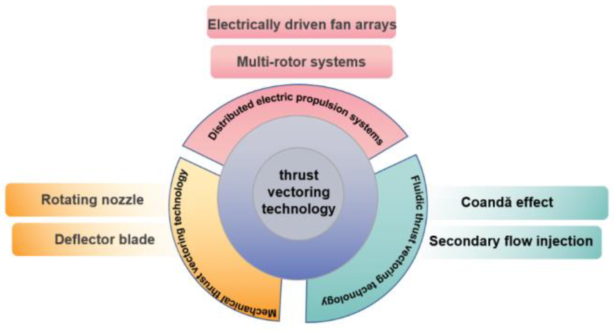
Figure 1. Technical routes of mainstream thrust vectoring technologies.
Drones 09 00689 g001
Figure 2. Thrust vector diagram.
Drones 09 00689 g002
Figure 3. Schematic of the fluidic thrust vector.
Drones 09 00689 g003
Figure 4. Schematic of the vector model of a quadcopter UAV.
Drones 09 00689 g004
Figure 5. Mechanical thrust-vectoring nozzle.
Drones 09 00689 g005
Figure 7. Bell UAV APT 70.
Drones 09 00689 g007
Figure 8. Omnidirectional thrust-vectoring hexacopter UAV [72].
Drones 09 00689 g008
Figure 9. Axial sectional view of a vector nozzle [73].
Drones 09 00689 g009
Figure 10. F-35 aircraft and its propulsion system [78].
Drones 09 00689 g010
Table 1. Comparison of Different Thrust Vectoring Technologies.
Thrust Vectoring TechnologyWeightThrust EfficiencyResponse TimeComplexityCostTechnology MaturityAdvantagesDisadvantage
Mechanical Thrust Vectoring TechnologyHeavyHighMediumHighHighHighSuitable for high-speed aircraft (such as fighter jets), with minimal thrust loss, optimised stealth performance, fully validated technology, and flexible flow regulation range.Reliance on mechanical transmission structures necessitates extended maintenance intervals, imposes stringent demands on the structural integrity of the chassis, requires substantial installation space, and demonstrates limited adaptability in low-speed scenarios.
Jet thrust vectoring technologyLightMediumQuickMediumMediumMediumNo complex mechanical transmission components, lightweight, suitable for small to medium-sized platforms. Certain types (such as fluid-operated) present low modification difficulty and offer distinct advantages in response speed.Airflow deflection readily leads to thrust loss and energy dissipation; requires additional components, resulting in increased structural complexity and weight, thereby reducing system reliability; entails higher fuel consumption; at low speeds, reduced airflow velocity diminishes vector control effectiveness and adversely affects low-speed manoeuvrability.
Distributed electric propulsionMediumMediumMediumMid-to-highMid-to-highMediumCapable of vertical take-off and landing, with low noise levels suited to urban environments (such as eVTOLs). Multi-motor coordination enhances flight safety, making it suitable for low-altitude, low-speed aircraft.Battery endurance is limited, multi-motor coordinated control presents significant challenges, ducting and wing surface structures impact range, high-altitude environmental adaptability is weak, and multi-rotor configurations are prone to aerodynamic interference.
Table 2. Comparison of Different Control Methods.
Control MethodApplicable ScenariosAdvantagesDisadvantages
ADRC [53]Strongly nonlinear systems under multi-source disturbances (such as unmanned aerial vehicle flight at high angles of attack)1. Real-time disturbance estimation and compensation achieved via the Expanded State Observer (ESO), offering robust performance;
2. The enhanced PTESO converges within a predetermined timeframe with minimal estimation error;
3. Supports independent multi-channel control, accommodating thrust vector nozzle constraints.
1. The convergence speed and accuracy of traditional Linear Expansion State Observers (LESOs) are constrained by bandwidth parameters;
2. Actuator constraints are not explicitly handled, necessitating additional optimisation.
MRAC [54]System parameter perturbations, sudden disturbance scenarios (such as thruster failures, sudden load changes, etc.)1. The introduction of a model reference adaptive layer enables rapid compensation for sudden disturbances;
2. Performance in hardware-in-the-loop testing shows significant improvement over traditional PID control;
3. High global performance index.
1. The fundamental MRAC exhibits insufficient robustness against strong nonlinearities and high-frequency disturbances;
2. It necessitates the design of complex feedback linearisation and immunity-inspired mechanisms, resulting in relatively high algorithmic complexity.
Backstepping [55]Fault-tolerant control of nonlinear systems, multi-variable coupled scenarios (such as rudder failure)1. A systematic design methodology adapted to highly non-linear dynamics;
2. Fault identification achievable through integrated cascaded observers;
3. Enhanced wind disturbance resistance and robustness following the incorporation of command filtering techniques.
1. Traditional backstepping control is susceptible to high-frequency dynamics and requires additional suppression;
2. In fault scenarios, inertial parameters must be updated in real time, entailing significant computational overhead.
SMC [56]System uncertainty, actuator saturation constraint scenarios1. Finite-time convergence characteristics with rapid response;
2. Strong interference resistance and insensitivity to parameter perturbations;
3. Integrated anti-saturation auxiliary system capable of handling thrust saturation and wind disturbances.
1. Traditional SMC suffers from chattering issues, necessitating optimisation of the sliding mode surface design;
2. Fixed sliding mode parameters exhibit poor adaptability under time-varying parameter scenarios.
Table 3. Comparison of the effect of the improved A* algorithm [60].
IndicatorTraditional A* AlgorithmImproved A* AlgorithmLift Rate
Path length (complex environment)24.38 m26.14 m+7.2%
Search node (complex environment)14397−32.2%
Number of touchdowns (complex environment)60−100%
Number of route points (after optimisation)236−73.9%
Total steering angle (after optimisation)225°180°−20.0%
Table 4. Comparison of Different Path Planning Algorithms.
Algorithm CategoryAlgorithm NameApplicable ScenariosAdvantagesDisadvantages
Graph search-based algorithmImprovement of the A* algorithm [68]In complex three-dimensional environments for unmanned aerial vehicles (such as areas with dense base stations or low-altitude scenarios with numerous obstacles), both safety and real-time performance must be prioritised.1. Optimises the heuristic function to enhance search efficiency and reduce redundant path points;
2. Introduces an obstacle distance penalty mechanism to mitigate collision risks;
3. Path smoothness and navigation efficiency are relatively favourable.
1. Path length may increase slightly in complex environments;
2. Heuristic function weighting factors require scenario-specific tuning, with general applicability yet to be enhanced.
Spatio-temporal Dijkstra algorithm [69]Multi-UAV collaborative missions (such as swarm operations and multi-task conflict avoidance) require conflict-free path planning.1. Overcomes the limitation of traditional algorithms that output only a single shortest path, enabling the recording of multiple predecessor nodes;
2. Integrates a time window model to achieve conflict-free multi-vehicle path planning;
3. Supports task prioritisation to enhance overall planning efficiency.
1. Static time window design exhibits insufficient adaptability to dynamic obstacles;
2. Computational complexity increases linearly with the number of nodes.
Bionics-inspired algorithmsChaotic Particle Swarm Optimisation [70]In complex three-dimensional urban environments (such as densely built-up areas), global search and avoidance of local optima are required.1. Incorporating chaotic sequences enhances global search capabilities and reduces the probability of becoming trapped in local optima;
2. The fitness function can integrate multiple objectives (such as economic benefit, height, and obstacle avoidance);
3. Iterative convergence speed is superior to that of traditional particle swarm optimisation.
1. The number of particles and iteration count require careful balancing, as computational costs are relatively high;
2. Paths may fluctuate in highly dynamic environments.
Adaptive Ant Colony Algorithm [71]Areas of dense vegetation and complex terrain (such as in LiDAR surveying) require paths with low vegetation coverage.1. Dynamically updates pheromone evaporation coefficients to enhance convergence speed;
2. Optimises path length planning to improve task execution efficiency (e.g., LiDAR ground point acquisition efficiency);
3. Path nodes feature low vegetation coverage, enabling adaptation to complex terrain.
1. The initial distribution of pheromones significantly impacts algorithm performance;
2. Deadlock is prone to occur in densely obstructed environments, necessitating additional obstacle avoidance strategies.
Integration of relevant technologiesA*-PSO convergence architecture [66]Complex battlefield environments (such as penetrating radar threat zones) require low probability of detection and short flight paths.1. Combining A*’s discrete path generation capability with PSO’s trajectory optimisation capability yields superior path performance;
2. Reduces environmental threats (such as radar detection probability), thereby enhancing mission success rates;
3. Significantly reduces runtime compared to single algorithms.
1. The parameter coordination between A* and PSO requires meticulous fine-tuning;
2. During dynamic threat updates, the efficiency of re-planning needs improvement.
ABC-RRT* [67]Complex battlefield environments (such as penetrating radar threat zones) require low probability of detection and short flight paths.1. Combines the global exploration capabilities of the Artificial Bee Colony (ABC) algorithm with the path optimisation features of RRT*, achieving superior path length;
2. Significantly reduces convergence iterations and simulation time while maintaining high stability;
3. Suitable for real-time obstacle avoidance requirements in dynamic environments.
1. Under high-density obstacles, random sampling of RRT* may result in local path redundancy;
2. The algorithm exhibits high fusion complexity, leading to significant engineering implementation challenges.
Disclaimer/Publisher’s Note: The statements, opinions and data contained in all publications are solely those of the individual author(s) and contributor(s) and not of MDPI and/or the editor(s). MDPI and/or the editor(s) disclaim responsibility for any injury to people or property resulting from any ideas, methods, instructions or products referred to in the content.