Article

Risk Assessment and Motion Planning for MAVs in Dynamic Uncertain Environments

1
College of Aerospace Science and Engineering, National University of Defense Technology, Changsha 410073, China
2
Defense Innovation Institute, Chinese Academy of Military Sciences, Beijing 100071, China
3
Intelligent Game and Decision Laboratory, Beijing 100071, China
*
Author to whom correspondence should be addressed.
Drones 2024, 8(9), 497; https://doi.org/10.3390/drones8090497
Submission received: 21 August 2024 / Revised: 9 September 2024 / Accepted: 10 September 2024 / Published: 18 September 2024

Abstract

:
Risk assessment to quantify the danger associated with a planned trajectory is critical for micro aerial vehicles (MAVs) navigating in dynamic uncertain environments. Existing works usually perform risk assessment by reasoning the occupancy status of the MAV’s surrounding space which only incorporates the position information of the MAV and the obstacles in the environment. In this paper, we further consider the MAV’s motion direction in risk assessment to reflect the fact that the obstacles in front of the MAV pose a higher risk while those behind pose a lower risk. In particular, we rely on a particle-based dynamic map which consists of a large number of particles to represent the local environment. The risk is defined to evaluate the safety level of a subspace in the map during some time interval and assessed by reasoning the occurrence of particles in the subspace. Those particles around the MAV are assigned different weights taking into account their relative positions to the MAV and its motion direction. We then incorporate the proposed risk assessment method into MAV motion planning by minimizing both the path length and the associated risk to achieve safer navigation. We compared our method with several state-of-the-art approaches in PX4+Gazebo simulations and real-world experiments. The results show that our method can achieve a 15 % higher collision avoidance rate and a 20 % lower flight risk in various environments with static and dynamic obstacles.

1. Introduction

In the realm of MAV motion planning and autonomous navigation, risk assessment is indispensable. Current research in this domain has predominantly focused on mapping risk by attributing it to the occupancy status of positions within a space, an approach that overlooks the dynamics inherent in both the environment and the MAV itself. The conventional assumption during obstacle avoidance routines is that all barriers are stationary, as noted in [1]. However, real-world scenarios often present increasingly complex flight conditions, particularly due to the presence of dynamic obstacles such as pedestrians and other mobile robots [2,3]. While there is a growing recognition of the need to address environmental dynamics, the consideration of MAV dynamics remains relatively underdeveloped. This gap in research results in suboptimal motion planning and significantly elevates the risk of collision during flight. precise risk assessment is imperative for guaranteeing the safe and reliable operation of drones in intricate and continuously evolving environments.
The challenge of performing risk assessment on the flight trajectory of a MAV presents a substantial issue, especially in the context of real-time, online evaluation and the integration of these risk factors into the MAV’s trajectory planning process. Furthermore, obstacles encountered along the direction of flight at equivalent distances represent a higher level of risk compared to those in other directions. Notably, research examining the differential risk posed by the movement of drones themselves in such scenarios is sparse. Ongoing research in this area is imperative to achieve a deeper comprehension of the drone flight environment and to refine risk assessment methodologies accordingly.
In this paper, we introduce an approach for addressing the risk assessment challenge during drone flight within dynamic and uncertain environments. This method is designed to systematically tackle the issues previously discussed as shown in Figure 1. We then outline a conceptual framework for integrating risk considerations into the planning phase. The core objective of our research is to achieve a harmonious balance between enhancing flight safety and maintaining the operational efficiency of drones. A key innovation of our method lies in its consideration of MAV dynamics within the context of risk assessment, and its integration of risk as an integral component of motion planning. Specifically, we employ a particle-based dynamic map, populated with a large number of particles, to encapsulate both static and dynamic aspects of the environment as perceived by the MAV. We define the risk profile of the current subspace over a defined period using weighted risk particles. In contrast to previous risk assessments that were limited to static environments or focused solely on obstacles, our proposed methodology incorporates risk weighting influenced by the MAV’s dynamics into the motion planning process. This is achieved by minimizing both the path length and the associated risk, resulting in safer navigation. The varying weights are visually represented in a risk field that diverges from the MAV’s current position towards the direction of motion.
The main contributions of this paper are:
  • A rational and efficient risk definition. Our approach accounts for MAV dynamics, leading to the creation of a rational risk assessment potential field. This field is finely tuned to align with the MAV’s preferred motion magnitude and direction, ensuring that the risk assessment is sensitive to the vehicle’s operational characteristics and navigational intent.
  • A dynamic risk-aware MAV motion planning method in dynamic uncertain environments. In this paper, we propose an approach to motion planning for MAVs that considers a comprehensive set of risk factors. Our method focuses on increasing the safety of MAV flights by generating collision-free paths and reducing flight distances, while also incorporating risk assessment into the planning phase to account for varying levels of risk.

2. Related Work

2.1. Risk Assessment

The primary focus of risk assessment methods is to evaluate occupancy status and the probability of the surrounding space for MAV operations. Current approaches for assessing occupancy status typically only consider the positional data of the MAV and the obstacles present in the environment. Although non-map representations [2] are intuitive, the original data may contain significant noise, leading to poor accuracy and readability. The utilization of map representation has become prevalent in various applications. The geometric map employs basic geometric elements such as points, lines, and cubes to represent spatial information, as referenced in [4,5,6]. While it effectively simplifies map features, it faces challenges in accurately representing complex environments. On the other hand, the topology map, as detailed in [7,8], utilizes abstract nodes and edges to depict key positions, yet it tends to overlook the representation of local obstacles. Another approach, the occupancy grid map as described in [9], utilizes grid-based units with occupancy status, offering enhanced map representation capabilities. However, it primarily focuses on position information rather than motion and may exhibit limitations in accurately capturing dynamic environments.
For risk assessment methods of probability, the risk was first defined by the likelihood of not colliding with anything, as suggested by [10]. Ref. [11] used wavelets to reflect surrounding risk, ref. [12] represented the environment as a Gaussian process and obstacles with the threshold over the Gaussians, which discribed risk in Gaussian process. Ref. [13] presented a safety-aware perception method that utilizing control barrier functions (CBFs). Ref. [14] defined risk of action and utilized this for navigation in Bayesian Learning. Ref. [15] chose a simple heuristic of the probability of collision based on Boole’s inequality to represent risk. But existing risk assessment methods of probability are lack of inconsistent weight of surrounding risk caused by the movement of the MAV or environments. For example, a high-speed obstacle can cause higher level of risk threat than a low-speed one for action response of autonomous flight although the MAV can avoid collision in both situation, or in same distance the movement front obstacle risk is higher than the back of a high-speed MAV. For the movement of obstacle, ref. [16] used a dual-structure particle-based mapping approach, and it is capable of accurately and efficiently modeling both moving obstacles and stationary obstacles. And for the movement of the MAV, that is exactly what we present in this paper. Our method respects the basic logic of axioms in [17] to make our risk metric and assessment more physical value.

2.2. Risk-Aware Motion Planning

The prevailing approaches to motion planning can be categorized into three main types: sampling-based, optimizing-based, and learning-based methods.
Optimizing-based motion planning techniques typically involve transforming the environment into a more mathematically concise representation and formulating the trajectory planning problem as an optimization problem. Ref. [18] specifically focused on optimizing minimum probability of collisions with dynamic and unknown objects. Ref. [19] incorporated risk and uncertainty by using a chance constraint to quantify the probabilistic nature of these factors. Ref. [20] used multi segment polynomial trajectories as the basis and constructed risk-aware spatio-temporal safety corridors for optimization to solve. Ref. [21] found the optimal time allocation solution using mixed shaping quadratic optimization and linear search methods. But optimizing-based motion planning methods always can’t optimize to the most optimal solution and cause a huge computational burden to onboard computer.
Learning-based motion planning methods have emerged with the rapid progress of deep learning in recent years. The inputs to networks can be diverse, and learning methods can also be imitative learning [22] or reinforcement learning [23]. Reinforcement learning methods are more popular, Ref. [24] presented a learning-based approach to address the problem of multi-robot navigation while avoiding probable future collisions. ref. [25] introduced a local risk map and integrated it into the deep reinforcement learning architecture. But learning-based motion planning methods are still in an emerging stage of development, and many operations only exist in theory and are difficult to apply in practice.
Sampling-based motion planning methods generally search for available motion primitives in the control space [26] or state space [27], the motion primitives are generally high degree polynomials that can ensure smoothness and have analytical solutions, such as fifth or seventh degree polynomials derived from the minimum jerk [28] or minimum snap [29]. One of the major benefits of sampling based motion planning is not requiring analytical solutions to increase computational efficiency, but the processing objective of risk is located on path finding more rather than safety of the MAV. Building upon the research presented in reference [30], our study introduces an approach of sampling-based motion planning that incorporates risk assessment and implements the MAV safety considerations in path finding.

3. Preliminaries

In this section, we briefly go through the mapping methodology and risk unit used in our algorithm.
We represent real-world scenarios that involve barriers in various motion modes with the dual-structure particle-based dynamic occupancy map (DSP Map) as following [16], which is a map form that uses particles as the basic representation unit to represent the shape and motion of obstacles in the environment where the MAV is located at the particle level, achieving efficient estimation of the occupancy status of dynamic and static obstacles in continuous space and more accurate risk assessment. As shown in Figure 2, let M denote the neighborhood map space of the MAV, which is sized by a cuboid boundary. At the center of this cuboid is the MAV. We decompose each obstacle in the space of neighborhood map into point objects, and these point objects are used to estimate the occupancy status at an arbitrary position in the map. All point objects move independently. The DSP map is a method used to depict static or dynamic barriers of any shape because of construction from particles. Let X t 0 = [ p t 0 , v t 0 ] T R 6 represent the state of one point at this time t 0 , p t 0 R 3 and v t 0 R 3 represent the position and velocity of this point respectively. So all points form a random and finite set X t 0 = { x t 0 ( 1 ) , . . . . . . , x t 0 ( k ) } ( k > 0 ), which includes positions and velocities of all points in M at this time t 0 . The DSP map estimates the probability hypothesis density (PHD) [31] of X t 0 instead of calculating the state of every particle point. Let D X t 0 represents the PHD of X t 0 and the first-order moment of X t 0 describes the hypotheses with different states x t 0 X t 0 . The estimation of D X t 0 depends on a sequential Monte Carlo PHD (SMC-PHD) filter [32] and then output is a set of n t 0 particles that every particle(i { 1 , . . . . . . , n t 0 } ) has a weight ω t 0 i and a state χ t 0 i . According to [16], let D X t 0 ( x t 0 ) be the current PHD at state x t 0 and then D X t 0 can be estimated with particles with:
D X t 0 ( x t 0 ) = i = 1 n t 0 ω t 0 i δ ( x t 0 x t 0 ( i ) )
where δ (.) is the Dirac function and x t 0 ( i ) , ω t 0 i are updated with the MAV motion and perception changed in filter. The number of particles n t 0 always as large as one million based on the Law of Large Numbers [16].
To enhance adaptability to various map types and improve computational efficiency, the particle points risk of obstacles are simplified to the conventional occupancy type, where 0 represents vacant space and 1 represents occupied space, and the method of simplification we present at the beginning of Section 4.4. Then in the cuboid space, the 3-dimensional environment space is represented by C R 3 . And for necessity of planning, C is consistently divided into a discrete space S . This discrete space is used to construct an occupancy grid map, which reflects the risk of particle points. The value of s S is binary, either 0 or 1, indicating whether the corresponding location represents a free collision space or an obstacle occupancy space. The obstacle region S o b s S is the prohibited zone to flight, and the cost associated with this region is precisely equal to 1. It is assumed that the set of collision-free regions S f r e e S , which has a cost of 0, always includes at least one viable and feasible flight path from the starting position S s t a r t to the goal location S g o a l . Therefore:
S = S f r e e + S o b s ( S f r e e S o b s = )
S s t a r t , S g o a l S f r e e
To tally with the limitation of real flight orientation and observation, we choose the front side of the MAV and make it on the top of the view pyramid as shown in Figure 2. In the occupancy grid map S , we can use every particle’s state X t 0 ( i ) = [ p t 0 ( i ) , v t 0 ( i ) ] T R 6 and weight ω t 0 i that estimated by PHD to map current occupancy situation in the boundary of view pyramid.

4. Methodology

This section begins with an overview of our motion planning system, followed by an explanation of the risk definition and the process employed in our risk-aware motion planning algorithm.

4.1. System Overview

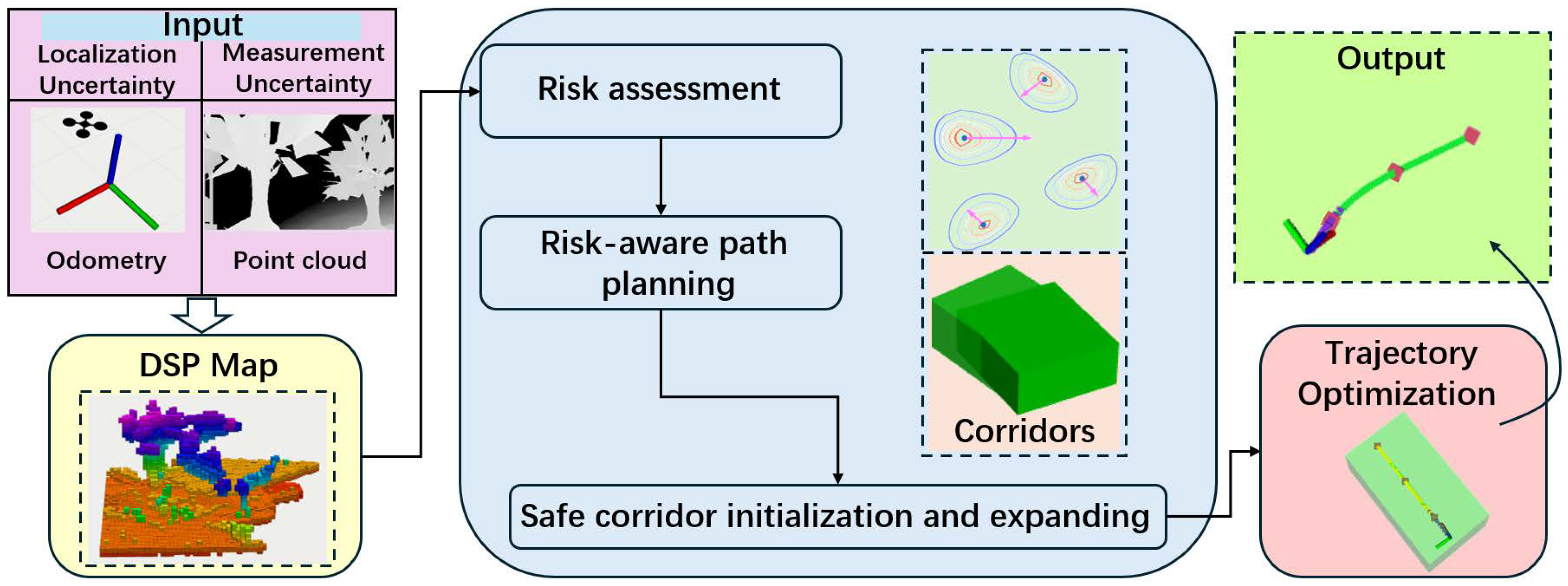
The structure of our system is shown in Figure 3, the major modules include:
(a) DSP and occupancy grid map building: In Section 3, we present the DSP and occupancy grid map construction methods. The DSP map, an integral component of the mapping process, employs particle points to effectively depict the local environment, enabling accurate representation of both static and dynamic obstacles of varying shapes. This facilitates a comprehensive evaluation of risk in the vicinity of the MAV. Subsequently, we outline the assessment of flight risk within an occupancy grid map, enhancing the applicability and ease of integration for our motion planning processes.
(b) Risk-aware path planning and safety corridor generation: We dynamically distribute various weights around the moving MAV to assess flight hazards and incorporate them into the motion planning process. Subsequently, we utilize a dynamic risk-aware A* algorithm to construct a segmented reference path. By extending this path, we are able to establish safety corridors that prioritize the safety of the MAV’s trajectory.
(c) Trajectory optimization: The safety corridors are considered constraints, allowing for the formulation of a QP problem aimed at optimizing a flight trajectory. Subsequently, the obtained flight trajectory information can be utilized to send parameters to a trajectory tracker for controlling the MAV.

4.2. Occupancy Risk Cost

As previously discussed, the states and weights of particle points provide a rapid means for risk assessment in MAV flight. This is due to the DSP map’s capability to facilitate continuous occupancy mapping of dynamic environments, which outperforms other methods in terms of risk mapping efficiency [16]. The process involves assuming a standard risk measure space, which encompasses a user-defined geographical area along with the safety corridor employed in our method. Risk is quantified by evaluating the safety level within this space over a specified time interval. Within this framework, risk unit particle points are established, each assigned dynamic weights that vary according to location within the risk measure space. This space serves as a tool to assess the risk scenario surrounding the MAV in its current operational state, with the risk assessment being derived from the weights of the particle points within it.
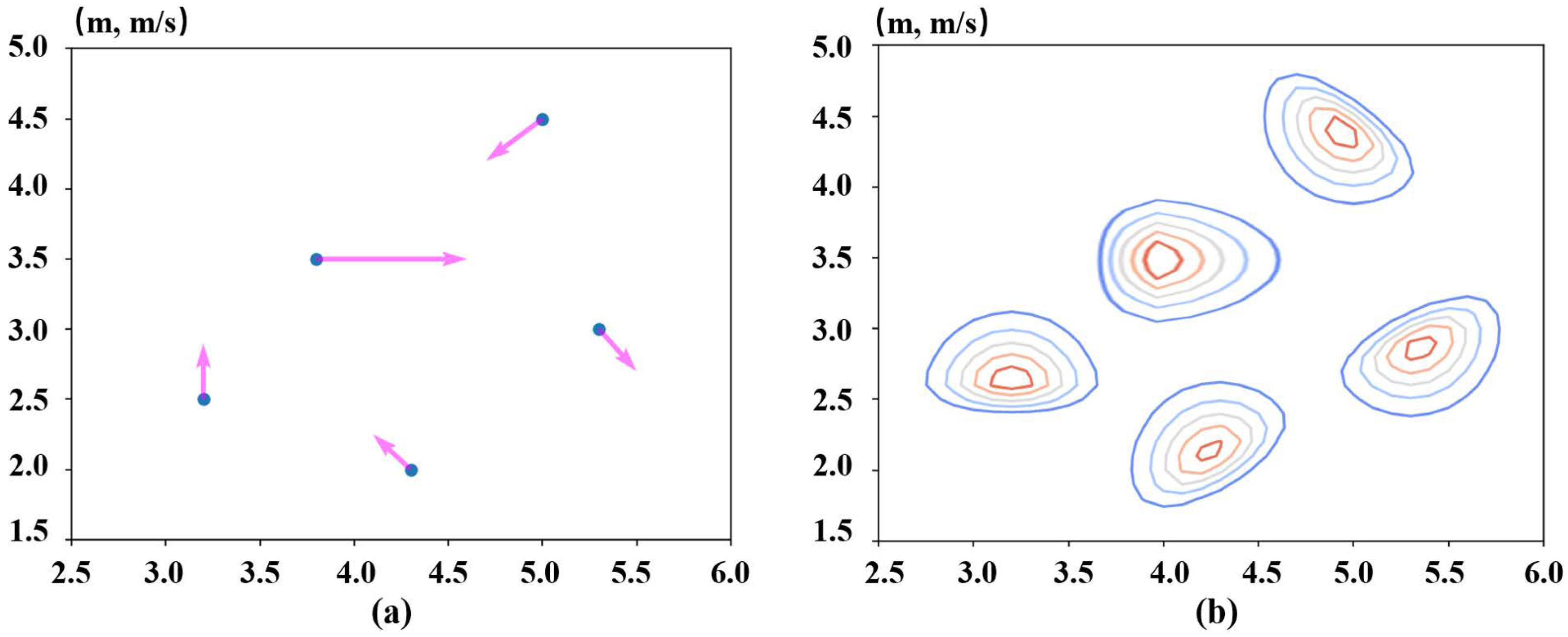
Different from frequently-used methods to consider the information of environment in static or average ways, we have considered the movement of the MAV when dealing with environment risk. In reality, considering an environment Q R 3 , with points in Q denoted q . For the MAV in the environment, we donate the position of it as u . Assuming the MAV has double-integrator dynamics, which means we can get velocity u ˙ and acceleration u ¨ of it. We adopt the occupancy risk cost of [33] and make some reasonable adjustment to reflect the MAV’s location and intended direction of motion weights well in risk as shown in Figure 4, which means different locations in the occupancy map around the MAV have different risk costs due to the MAV’s motion state. The occupancy risk cost H is defined:
H ( q , u , u ˙ ) = exp q u T Ω q u 1 + exp α u ˙ T q u
where Ω is the diagonal matrix of the inverse square of the standard deviation and Ω = diag 1 σ x 2 , 1 σ y 2 , 1 σ z 2 in our three-dimensional flight environment. For better expressing the performance of risk cost at the speed what we set in our simulation and experiment, α = 4 is assigned because different intervals of speed and acceleration are corresponding to different values of α for better performance in planning and α = 4 is the appropriate value in MAV dynamic situation.

4.3. Risk Definition

Note that the construction of H is a Gaussian peak multiplied by a logistic function. The Gaussian peak represents an estimate of the MAV’s position, while the logistic function skews this estimate in the direction of the velocity. By skewing the weight allocation from the agent current position to the direction of motion in this way, we have achieved a more reasonable assessment of risk and more reliable navigation and planning on board when the MAV flights dynamically. Figure 4 illustrates simplified contours of the occupancy risk cost H from the location skewing to the direction of velocity of the MAV various flight directions in R 2 to show the risk field. So we can update the weights of particle points surrounding the MAV:
ω t 0 * = H ( p t 0 , u , u ˙ ) ω t 0
where p t 0 and ω t 0 are the position and weight of one particle point, which form the state mentioned in Section 3. Then the summation of risk weights in risk measure space E k during t 0 to t j ( t i [ t 0 , t j ] ) is set to represent the risk level for this period:
Risk E k , t 0 , t j = t 0 t j m = 1 n ω t i * d t
Risk E k , t 0 , t j t = t 0 , t 0 + δ t , , t j m = 1 n t w t * ( m ) δ t
where Risk indicates the predicted risk values surrounding the MAV in the space E k from t 0 to t j , and we discretize the calculation process of Risk in practical application and discretize it in time domain using δ t as the unit. From the perspective of computational complexity, risk is defined in the constant time interval, and calculated as a linear traversal calculation in the summation of particle risks, thus having a lower computational complexity. That is how we define risk in mathematics directly and in Section 4.4 we transform it to contribute the planning.

4.4. Risk-Aware Path Planning

Our planning method is based on kino-dynamic A* planning method but takes risk weights and the occupancy risk cost H mentioned in Section 4.2 of particle points into consideration. To simplify risk to the conventional occupancy type, we set a risk threshold R 0 ( 0 , 1 ) and it is changed by different complexity of environment and safety demand. According to Equation (5b), we set E k as a unit space E i of the occupancy grid map around the MAV:
O E i = 0 , Risk E i , t 0 , t j < R 0 1 , Risk E i , t 0 , t j R 0
where O E i is the occupancy state of E i . Based on the occupancy grid map, let Σ be the set of all paths and the single path σ Σ is a set of discrete location points s σ in collision free space S f r e e S . The path planning algorithm searches for an optimal collision free path σ * from s s t a r t to s g o a l which depends on different demands of cost function f : Σ R 0 and the objective of minimization. In our approach, our minimization objective is flight risk, which conducts optimal path generation without collision by minimizing risk. Then the optimal path can be solved from the following cost optimization function:
σ * = a r g min f σ Σ ( σ ( λ ) )
where we define for normalization that σ ( 0 ) = s s t a r t , σ ( 1 ) = s g o a l and λ [ 0 , 1 ] , σ ( λ ) S f r e e .
Our proposed solution is akin to the kino-dynamic A* method in that it accepts abstract nodes as inputs. The cost associated with these nodes is computed by combining the traditional cost objective with the risk incurred due to the interaction between the MAV and the environment in a given state. Moreover, our algorithm is adept at functioning within a three-dimensional spatial context, where each node corresponds to a distinct locational point that could potentially be part of the intended flight path. The resultant output is a back-pointer path, which constitutes a sequence of nodes, beginning from the local goal and retracing its steps back to the local starting point. Similar to the cost function employed in the kino-dynamic A* algorithm, our optimization strategy is designed to minimize the cost function f ( s ) r i s k , thereby identifying a collision-free path:
f ( s ) = g ( s ) + k · h ( s )
η ( s ) = Risk E s , t 0 , t j R 0
f ( s ) r i s k = ( 1 + η ( s ) ) f ( s )
where Risk E s , t 0 , t j is risk of the space around node s . Equation (7) is cost function of The kino-dynamic A* algorithm and in our method g ( s ) is the motion time cost of the path from current node s to the local start node s s t a r t . h ( s ) is the heuristic cost that estimated motion time cost of the optimal flight path from current node s to the local goal node s g o a l and constant k is an adjustment variable that sets different values for different situation. In Equation (8b), the dynamic risk factor η ( s ) ( η ( s ) 0 ) describes the MAV flight risk for this node s . Hence, the cost function f ( s ) r i s k in our method includes the estimated motion time cost and risk cost corresponding to the most optimized path for comprehensive consideration of shorter motion time and lower risk from s s t a r t to s g o a l , passing through current node s .

4.5. Safety Corridor Generation and Trajectory Optimization

The generation of our safety corridor and trajectory optimization strategies is informed by the works presented in [20,29]. Following the acquisition of reference path nodes, we generate a series of sampled accelerations that encapsulate the MAV’s motion across three axes, an essential requirement given the environment’s dynamic and unforeseeable nature. Between pairs of reference path nodes, we apply the principles of uniform acceleration motion from kinematics to calculate the position of the subsequent intermediate node at each sampling time step.
Using these two intermediate nodes as a foundation, we set the initial width step for the envelope construction. This envelope is then expanded along the xyz axes until it intersects with a grid that exceeds the predefined risk threshold. The number of such expanded envelopes constitutes the safety corridor.
In the domain of trajectory optimization, the initial trajectory is treated as a polynomial subject to various constraints. These include boundary value constraints, corridor constraints, continuity constraints, as well as constraints on maximum acceleration and velocity. By transforming the corridor constraints into linear constraints relative to the poles of each polynomial segment, the trajectory optimization problem is reduced to a quadratic programming (QP) issue, which can be addressed with high efficiency [34].

5. Results

In this section, we commence by validating the effectiveness of our risk management approach through a comparative analysis with several state-of-the-art methodologies, utilizing both simulation and empirical testing. Building on this, we present extensive real-world testing to bolster the credibility of our strategy. Furthermore, we perform simulations and field trials across a diverse range of environmental conditions to comprehensively assess the robustness and applicability of our approach.

5.1. Simulation Tests

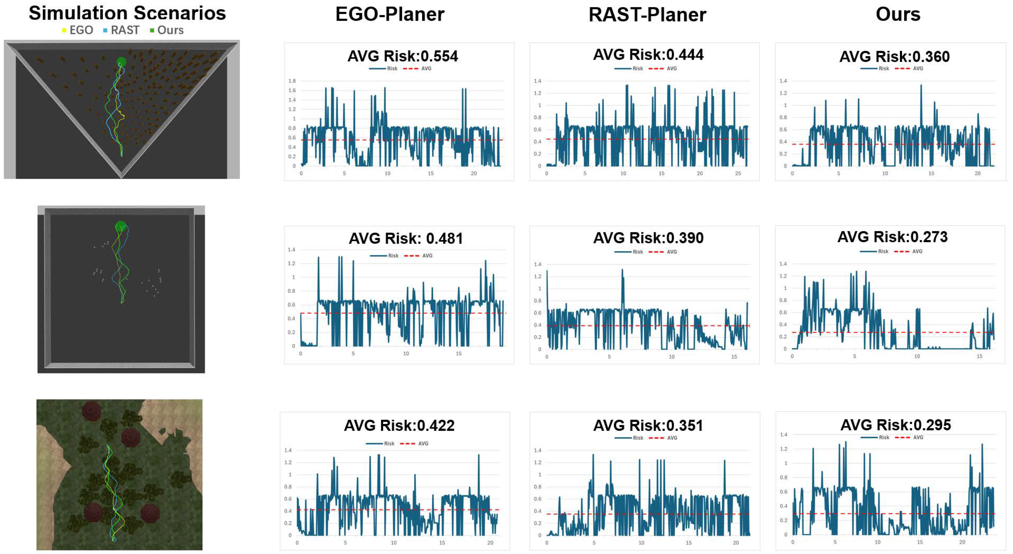
Our simulation experiments were executed utilizing the IRIS MAV, which was integrated with an Intel® RealSense™ depth camera D435i (Intel, Santa Clara, CA, USA) and powered by PX4 firmware. These tests were performed within the Gazebo simulation environment on a laptop equipped with an Intel® Core™ i9-12900HX CPU (Intel, Santa Clara, CA, USA). The full physical engine of Gazebo was activated to accurately replicate the environmental dynamics and the MAV’s behavior. The study employed three distinct simulation scenarios depicted in Figure 5, encompassing a dense static obstacle environment, a dense dynamic obstacle environment simulating crowd dynamics [35], and real-world simulation settings.
For comparison purposes, we selected EGO-Planner [36] as a representative MAV trajectory planning method and RAST-Planner [20] as a risk-aware planning method. EGO Planner is a gradient based planning framework without Euclidean Signed Distance Field (ESDF), which significantly improves computational efficiency while ensuring planning success rate. This enables it to run smoothly on onboard computers and is widely used in the planning framework of many autonomous MAVs. RAST Planner is a method for MAV navigation in dynamic uncertain environments, which, like our method, uses risk assessment to guide subsequent planning. It can be deployed and operated on onboard computers. Therefore, the purpose of choosing RAST Planner is to find the more effective planning method in the field of risk assessment guided planning. To account for measurement uncertainty, the official d435i simulation model was utilized to simulate realistic measurement noise. For localization uncertainty, Gaussian noise with values ε = 0 , 5 , 10 cm was added to the ground truth odometry to approximate errors that may occur in practical applications.
Forty separate tests were conducted within each simulated environment, employing both our proposed method and the comparative methods. A height restriction of 1.5 m was imposed to prevent the MAV from flying above static and dynamic obstacles. Additionally, a maximum velocity limit of 3 m/s was set to ensure the safety of the simulation.
Figure 6 illustrates the path and risk profiles for the EGO-Planner (represented in yellow), RAST-Planner (in blue), and our proposed method (in green) across three distinct simulation environments. The figure demonstrates that our approach tends to yield safer flight paths with reduced risk, enabling the MAV to navigate more smoothly while minimizing the need for hovering.
Table 1 provides a comprehensive summary of the quantitative comparison results between our method and alternative trajectory planning techniques. It reveals that our method significantly improves safety by leveraging a defined risk field and by incorporating flight risk as a critical factor within the kino-dynamic A* planning framework, particularly in scenarios that mimic the sim-world environment. Our method achieves a 20% reduction in potential collisions compared to a no-risk-aware approach, and an additional 10% decrease when contrasted with a risk-aware method, without compromising the overall planning efficiency.

5.2. Real-World Tests

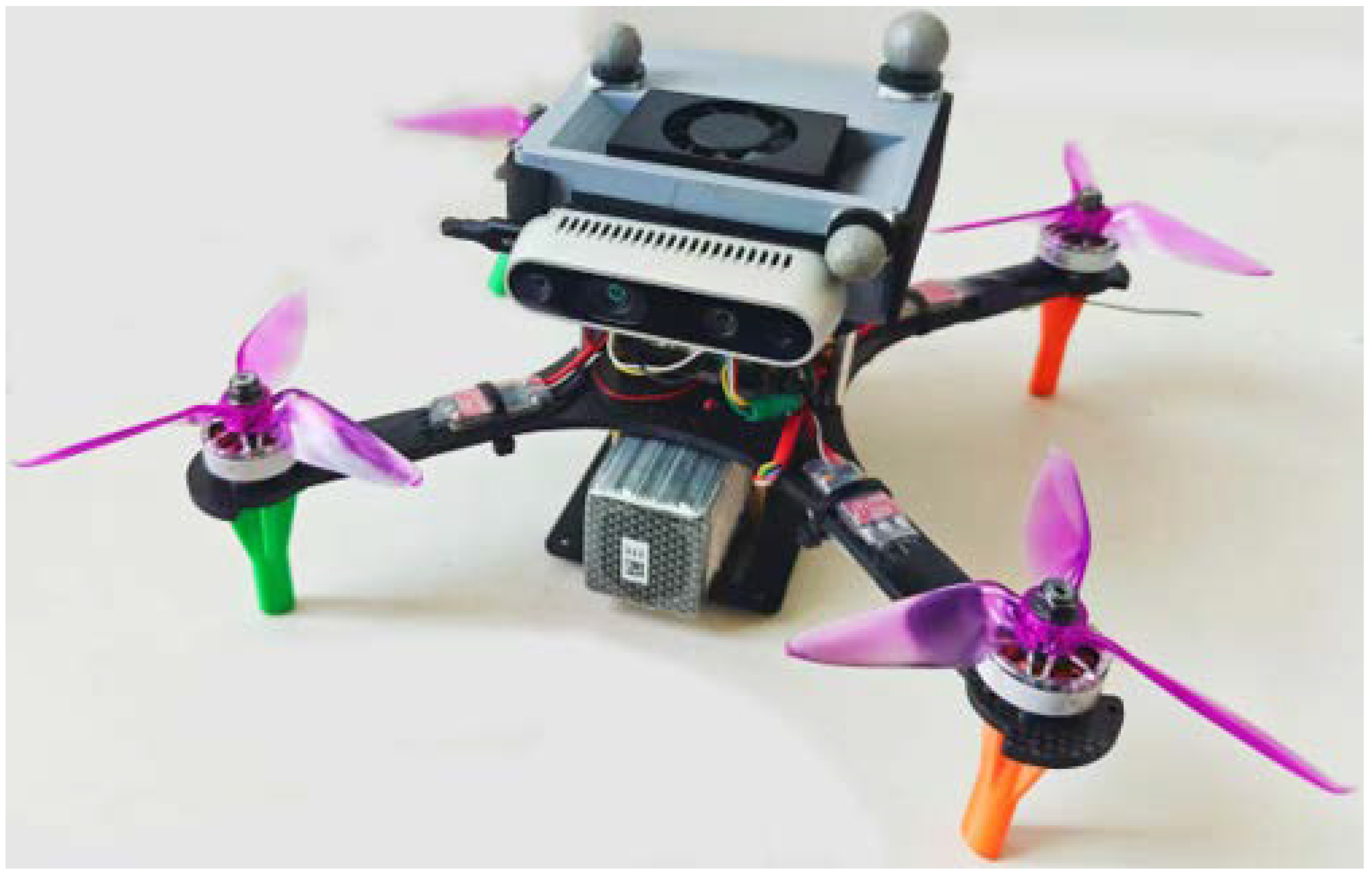
In the real-world tests, we replicated the setup from our simulations using a MAV equipped with PX4 flight control software v1.12, an NVIDIA Jetson Xavier NX (NVIDIA, Santa Clara, CA, USA) computing board, and an Intel® RealSense™ depth camera D435i. The MAV used in our experiments is depicted in Figure 7. The camera’s measurement noise was less than 1% within a two-meter range, and the Vicon system provided the MAV’s position and motion data with localization noise less than 1 cm. We conducted real-world tests against RAST-Planner [20] to assess and validate the efficacy of our method in obstacle avoidance scenarios.
Figure 8 visualizes the planned flight corridors and risk levels for both RAST-Planner and our method during the MAV’s flight. The intensity of the green blocks indicates the risk level, with darker shades representing higher risk. As depicted in the snapshot(c), in practical operations, when confronted with obstacle risks, RAST-Planner tends to adopt a more aggressive and direct path planning approach, whereas our method prioritizes risk assessment to achieve safer flight. Consequently, the avoidance of high-risk areas results in smoother flight profiles, with controlled sudden speed changes and attenuations. This is why the path length may not always be optimal, and the overall flight completion time may be shorter.
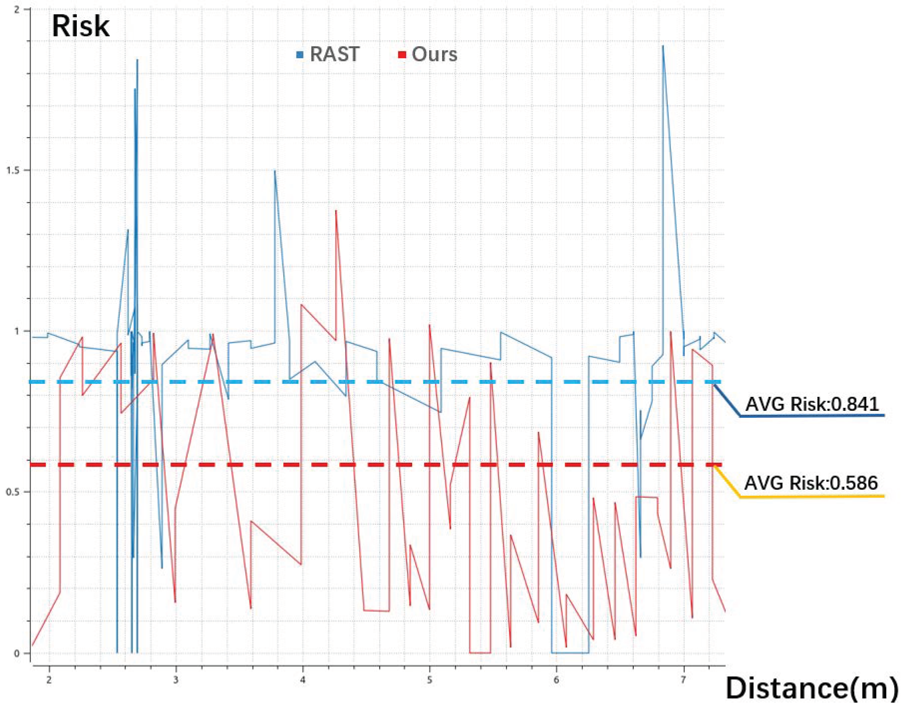
The performance of risk assessment within our planning method is further illustrated in Figure 9. The offboard mode transition occurred at x = 2 m, and the goal was set at x = 7 m. The sharp change in risk plotting is due to the sudden appearance and disappearance of obstacles or dynamic obstacles are perceived in the field of view during flight. Throughout the flight, the risk level of our method’s path was consistently lower than that of RAST-Planner. The lower peak risk indicates that our method can choose to avoid obstacles at farther and safer distances. At the same time, since the planning considers risk, the higher frequency of low-risk up and down lines indicate that our method’s obstacle avoidance response is more sensitive. Additionally, in instances where re-planning was necessary, such as the dense line zone at x ( 2 , 3 ) m in Figure 9, our method delivered a low-risk, smooth path, significantly enhancing flight efficiency and reducing the risk by approximately 20% for safety purposes.

6. Conclusions

In this paper, we introduce a precise risk definition that accurately captures the environmental hazards faced by the MAV, along with an online path planning methodology for MAVs. This approach is designed to integrate higher-probability collision avoidance and optimize flight trajectory efficiency.
Our findings, supported by both simulated and real-world datasets, indicate that our method results in more judicious flight decision-making and improved safety outcomes due to our refined risk definition. This has resulted in a 15% increase in collision avoidance capabilities and a 20% reduction in flight risk across diverse environments featuring static and dynamic obstacles. The efficacy of our trajectory planning module is substantiated through successful real-time, online navigation in both simulated and field experiments.

Author Contributions

Conceptualization, X.X. and H.Z.; methodology, X.X. and H.Z.; software, X.X.; validation, X.X.; formal analysis, X.X. and H.Z.; investigation, X.X. and H.Z.; writing—original draft preparation, X.X.; writing—review and editing, H.Z. and W.Y.; supervision, X.Z. and W.Y.; funding acquisition, H.Z. All authors have read and agreed to the published version of the manuscript.

Funding

This research was funded by National Natural Science Foundation of China (62303486).

Data Availability Statement

The data is contained within the article.

Conflicts of Interest

The authors declare no conflicts of interest.

References

  1. Oleynikova, H.; Lanegger, C.; Taylor, Z.; Pantic, M.; Millane, A.; Siegwart, R.; Nieto, J. An open-source system for vision-based micro-aerial vehicle mapping, planning, and flight in cluttered environments. J. Field Robot. 2020, 37, 642–666. [Google Scholar] [CrossRef]
  2. Lin, J.; Zhu, H.; Alonso-Mora, J. Robust Vision-based Obstacle Avoidance for Micro Aerial Vehicles in Dynamic Environments. In Proceedings of the 2020 IEEE International Conference on Robotics and Automation (ICRA), Paris, France, 31 May–31 August 2020; pp. 2682–2688. [Google Scholar] [CrossRef]
  3. Tordesillas, J.; How, J.P. MADER: Trajectory Planner in Multiagent and Dynamic Environments. IEEE Trans. Robot. 2022, 38, 463–476. [Google Scholar] [CrossRef]
  4. Mur-Artal, R.; Montiel, J.M.M.; Tardós, J.D. ORB-SLAM: A Versatile and Accurate Monocular SLAM System. IEEE Trans. Robot. 2015, 31, 1147–1163. [Google Scholar] [CrossRef]
  5. Pumarola, A.; Vakhitov, A.; Agudo, A.; Sanfeliu, A.; Moreno-Noguer, F. PL-SLAM: Real-time monocular visual SLAM with points and lines. In Proceedings of the 2017 IEEE International Conference on Robotics and Automation (ICRA), Singapore, 29 May–3 June 2017; pp. 4503–4508. [Google Scholar] [CrossRef]
  6. Jiang, R.; Yang, S.; Ge, S.S.; Wang, H.; Lee, T.H. Geometric Map-Assisted Localization for Mobile Robots Based on Uniform-Gaussian Distribution. IEEE Robot. Autom. Lett. 2017, 2, 789–795. [Google Scholar] [CrossRef]
  7. Konolige, K.; Marder-Eppstein, E.; Marthi, B. Navigation in hybrid metric-topological maps. In Proceedings of the 2011 IEEE International Conference on Robotics and Automation, Shanghai, China, 9–13 May 2011; pp. 3041–3047. [Google Scholar] [CrossRef]
  8. Gunathillake, A.; Huang, H.; Savkin, A.V. Sensor-Network-Based Navigation of a Mobile Robot for Extremum Seeking Using a Topology Map. IEEE Trans. Ind. Inform. 2019, 15, 3962–3972. [Google Scholar] [CrossRef]
  9. Hornung, A.; Wurm, K.M.; Bennewitz, M.; Stachniss, C.; Burgard, W. OctoMap: An efficient probabilistic 3D mapping framework based on octrees. Auton. Robot. 2013, 34, 189–206. [Google Scholar] [CrossRef]
  10. Fraichard, T. A Short Paper about Motion Safety. In Proceedings of the 2007 IEEE International Conference on Robotics and Automation, Rome, Italy, 10–14 April 2007; pp. 1140–1145. [Google Scholar] [CrossRef]
  11. Tsiotras, P.; Bakolas, E. A hierarchical on-line path planning scheme using wavelets. In Proceedings of the 2007 European Control Conference (ECC), Kos, Greece, 2–5 July 2007; pp. 2806–2812. [Google Scholar] [CrossRef]
  12. Dhawale, A.; Yang, X.; Michael, N. Reactive Collision Avoidance Using Real-Time Local Gaussian Mixture Model Maps. In Proceedings of the 2018 IEEE/RSJ International Conference on Intelligent Robots and Systems (IROS), Madrid, Spain, 1–5 October 2018; pp. 3545–3550. [Google Scholar] [CrossRef]
  13. Bena, R.M.; Zhao, C.; Nguyen, Q. Safety-Aware Perception for Autonomous Collision Avoidance in Dynamic Environments. IEEE Robot. Autom. Lett. 2023, 8, 7962–7969. [Google Scholar] [CrossRef]
  14. Richter, C.; Vega-Brown, W.; Roy, N. Bayesian Learning for Safe High-Speed Navigation in Unknown Environments. In Robotics Research: Volume 2; Bicchi, A., Burgard, W., Eds.; Springer International Publishing: Cham, Switzerland, 2018; pp. 325–341. [Google Scholar] [CrossRef]
  15. Tordesillas, J.; How, J.P. Deep-PANTHER: Learning-Based Perception-Aware Trajectory Planner in Dynamic Environments. IEEE Robot. Autom. Lett. 2023, 8, 1399–1406. [Google Scholar] [CrossRef]
  16. Chen, G.; Dong, W.; Peng, P.; Alonso-Mora, J.; Zhu, X. Continuous Occupancy Mapping in Dynamic Environments Using Particles. IEEE Trans. Robot. 2024, 40, 64–84. [Google Scholar] [CrossRef]
  17. Majumdar, A.; Pavone, M. How Should a Robot Assess Risk? Towards an Axiomatic Theory of Risk in Robotics. In Proceedings of the Robotics Research; Amato, N.M., Hager, G., Thomas, S., Torres-Torriti, M., Eds.; Springer: Cham, Switzerland, 2020; pp. 75–84. [Google Scholar]
  18. Şenbaşlar, B.; Sukhatme, G.S. Probabilistic Trajectory Planning for Static and Interaction-aware Dynamic Obstacle Avoidance. arXiv 2023, arXiv:2302.12873. [Google Scholar]
  19. Liu, T.; Zhang, F.; Gao, F.; Pan, J. Tight Collision Probability for UAV Motion Planning in Uncertain Environment. In Proceedings of the 2023 IEEE/RSJ International Conference on Intelligent Robots and Systems (IROS), Detroit, MI, USA, 1–5 October 2023; pp. 1055–1062. [Google Scholar] [CrossRef]
  20. Chen, G.; Wu, S.; Shi, M.; Dong, W.; Zhu, H.; Alonso-Mora, J. RAST: Risk-Aware Spatio-Temporal Safety Corridors for MAV Navigation in Dynamic Uncertain Environments. IEEE Robot. Autom. Lett. 2023, 8, 808–815. [Google Scholar] [CrossRef]
  21. Tordesillas, J.; Lopez, B.T.; Everett, M.; How, J.P. FASTER: Fast and Safe Trajectory Planner for Navigation in Unknown Environments. IEEE Trans. Robot. 2022, 38, 922–938. [Google Scholar] [CrossRef]
  22. Foehn, P.; Kaufmann, E.; Romero, A.; Penicka, R.; Sun, S.; Bauersfeld, L.; Laengle, T.; Cioffi, G.; Song, Y.; Loquercio, A.; et al. Agilicious: Open-source and open-hardware agile quadrotor for vision-based flight. Sci. Robot. 2022, 7, eabl6259. [Google Scholar] [CrossRef] [PubMed]
  23. Gandhi, D.; Pinto, L.; Gupta, A. Learning to fly by crashing. In Proceedings of the 2017 IEEE/RSJ International Conference on Intelligent Robots and Systems (IROS), Vancouver, BC, Canada, 24–28 September 2017; pp. 3948–3955. [Google Scholar] [CrossRef]
  24. Xie, Z.; Dames, P. DRL-VO: Learning to Navigate Through Crowded Dynamic Scenes Using Velocity Obstacles. IEEE Trans. Robot. 2023, 39, 2700–2719. [Google Scholar] [CrossRef]
  25. Yang, H.; Yao, C.; Liu, C.; Chen, Q. RMRL: Robot Navigation in Crowd Environments With Risk Map-Based Deep Reinforcement Learning. IEEE Robot. Autom. Lett. 2023, 8, 7930–7937. [Google Scholar] [CrossRef]
  26. Dharmadhikari, M.; Dang, T.; Solanka, L.; Loje, J.; Nguyen, H.; Khedekar, N.; Alexis, K. Motion Primitives-based Path Planning for Fast and Agile Exploration using Aerial Robots. In Proceedings of the 2020 IEEE International Conference on Robotics and Automation (ICRA), Paris, France, 31 May–31 August 2020; pp. 179–185. [Google Scholar] [CrossRef]
  27. Lopez, B.T.; How, J.P. Aggressive 3-D collision avoidance for high-speed navigation. In Proceedings of the 2017 IEEE International Conference on Robotics and Automation (ICRA), Singapore, 29 May–3 June 2017; pp. 5759–5765. [Google Scholar] [CrossRef]
  28. Mueller, M.W.; Hehn, M.; D’Andrea, R. A computationally efficient algorithm for state-to-state quadrocopter trajectory generation and feasibility verification. In Proceedings of the 2013 IEEE/RSJ International Conference on Intelligent Robots and Systems, Tokyo, Japan, 3–7 November 2013; pp. 3480–3486. [Google Scholar] [CrossRef]
  29. Mellinger, D.; Kumar, V. Minimum snap trajectory generation and control for quadrotors. In Proceedings of the 2011 IEEE International Conference on Robotics and Automation, Shanghai, China, 9–13 May 2011; pp. 2520–2525. [Google Scholar] [CrossRef]
  30. Primatesta, S.; Guglieri, G.; Rizzo, A. A Risk-Aware Path Planning Strategy for UAVs in Urban Environments. J. Intell. Robot. Syst. 2018, 95, 629–643. [Google Scholar] [CrossRef]
  31. Mahler, R.P.S. Statistical Multisource-Multitarget Information Fusion; Artech House, Inc.: London, UK, 2007. [Google Scholar]
  32. Vo, B.N.; Singh, S.; Doucet, A. Sequential Monte Carlo methods for multitarget filtering with random finite sets. IEEE Trans. Aerosp. Electron. Syst. 2005, 41, 1224–1245. [Google Scholar] [CrossRef]
  33. Pierson, A.; Schwarting, W.; Karaman, S.; Rus, D. Navigating Congested Environments with Risk Level Sets. In Proceedings of the 2018 IEEE International Conference on Robotics and Automation (ICRA), Brisbane, QLD, Australia, 21–25 May 2018; pp. 5712–5719. [Google Scholar] [CrossRef]
  34. Chen, J.; Liu, T.; Shen, S. Online generation of collision-free trajectories for quadrotor flight in unknown cluttered environments. In Proceedings of the 2016 IEEE International Conference on Robotics and Automation (ICRA), Stockholm, Sweden, 16–21 May 2016; pp. 1476–1483. [Google Scholar] [CrossRef]
  35. Helbing, D.; Molnár, P. Social force model for pedestrian dynamics. Phys. Rev. E 1995, 51, 4282–4286. [Google Scholar] [CrossRef] [PubMed]
  36. Zhou, X.; Wang, Z.; Ye, H.; Xu, C.; Gao, F. EGO-Planner: An ESDF-Free Gradient-Based Local Planner for Quadrotors. IEEE Robot. Autom. Lett. 2021, 6, 478–485. [Google Scholar] [CrossRef]
Figure 1. In the selection of numerous feasible planning paths, cluttered environment and high risk always lead complex planning strategy and low flight speed, risk assessment and taking it in planning can achieve a balance between minimizing risk and optimizing paths, making MAVs have a tendency to fly safe and fast.
Drones 08 00497 g001
Figure 2. The process of DSP Map generation and the pedestrians motion representation of particle points. Green pyramid is the map space and blue view pyramid is the visible space, then scanning from the MAV on the top of pyramids, obstacles can be mapped into the map space. The red dashed boxes represent the mapped pedestrians.
Drones 08 00497 g002
Figure 3. Systerm overview. Our method includes three modules and performs each module in order: map construction, motion planning with risk assessment, and trajectory optimization.
Drones 08 00497 g003
Figure 4. (a) Motion snapshots of the MAV in simplified R 2 environment with velocity direction indicated by purple lines. (b) Contours of occupancy risk cost H and the stretch direction is up to the velocity direction.
Drones 08 00497 g004
Figure 5. Simulation scenarios. Scenario A: A closed triangular area with dense cylindrical obstacles. Scenario B: A square with dense crowds walking in different directions. Scenario C: A park with oak trees and gazebos in addition to pedestrians. The walking speed in Scenario B and C ranges from 1.0 m/s to 1.5 m/s.
Drones 08 00497 g005
Figure 6. Traveled paths and in-process risk comparison in simulation scenarios. The x-axis represents flight time and the y-axis represents risk. EGO-Planner (yellow) [36] always generates a efficient and short path but results in a higher likelihood of collision. RAST-Planner (blue) [20] takes risk in consideration for reducing collision possibility finitely and sometimes makes the MAV stop moving and hover for re-planning. Our method (green) further reduces risk and makes the moving path more smooth and efficient.
Drones 08 00497 g006
Figure 7. MAV in our experiment. Hardware and sensors include a NVIDIA computing board and an Intel RealSense depth camera.
Drones 08 00497 g007
Figure 8. Real-world experiment compared with RAST-Planner [20]. Subfigure (a,b): Overview snapshot and D435i view. The red dashed block reflects excellent mapping for dynamics. Subfigure (c): Risk flight corridor of RAST-Planner (red dashed block) and our method.
Drones 08 00497 g008
Figure 9. Risk comparison between RAST-Planner and ours in real-world experiment. The x-axis represents moving distance in start-to-goal direction and the y-axis represents risk. The dense lines zone like at x ( 2 , 3 ) means the MAV stops moving and hovers for re-planning. Our method keeps lower risk most time and reduces frequency of re-planning efficiently.
Drones 08 00497 g009
Table 1. Comparison results with EGO-Planner [36] and RAST-Planner [20] in simulated MAV navigation experiments.
Envir.MethodSuss. Rate (%)Travel Time (s)Traj. Length (m)AVG Risk
StaticEGO60.023.4844.730.56
RAST62.526.2346.800.45
Ours75.021.7449.120.35
DynamicEGO47.531.4947.420.52
RAST55.028.3745.810.41
Ours62.529.5048.230.27
Sim-worldEGO57.520.7144.790.43
RAST72.521.4843.170.36
Ours80.023.7046.260.28
Disclaimer/Publisher’s Note: The statements, opinions and data contained in all publications are solely those of the individual author(s) and contributor(s) and not of MDPI and/or the editor(s). MDPI and/or the editor(s) disclaim responsibility for any injury to people or property resulting from any ideas, methods, instructions or products referred to in the content.