1. Introduction
Mobile Edge Computing (MEC) provides high-speed processing and large-scale distributed computing capabilities for many typical computing-intensive applications, such as automatic navigation, augmented reality, and remote control aircraft [
1]. The implementation of MEC relies on dispersed large-scale IoT devices and their wireless communication. The number of global IoT devices has increased rapidly in recent years [
2]. The increase in a large number of IoT devices has brought new challenges to mobile communication and service quality. At the same time, due to the limited computing power of IoT devices, additional computing resources are needed to support the effectiveness of services. In this context, UAVs have aroused significant research interest in academia due to their high maneuverability. As a result, UAV-assisted MEC has emerged as a prominent area of study [
3]. Meanwhile, the short-range communication characteristics of the UAV means that it cannot transmit data over limited resources over long distances. This requires the dispatch of UAVs to IoT-device-intensive areas through task allocation, path planning, and trajectory optimization to assist in completing tasks.
This paper considers assigning multiple UAVs to multiple task clusters for auxiliary calculations, and effectively formulating UAV flight routes through a heuristic strategy. Taking into account the different flight capabilities of the UAV and the constraints of the task time window, the goal of maximizing the QoS is achieved. In this paper, we consider both the number of tasks resolved by users and the data throughput in relay communications as elements of the Quality of Service (QoS) considerations. To our best knowledge, in the MTSP, the vast majority of UAVs studied are isomorphic [
2]. However, there are many UAV manufacturers, and there is no fixed unified standard for the UAVs produced, so the heterogeneous UAV model used in this article has different flight capabilities, i.e., maximum flight coverage [
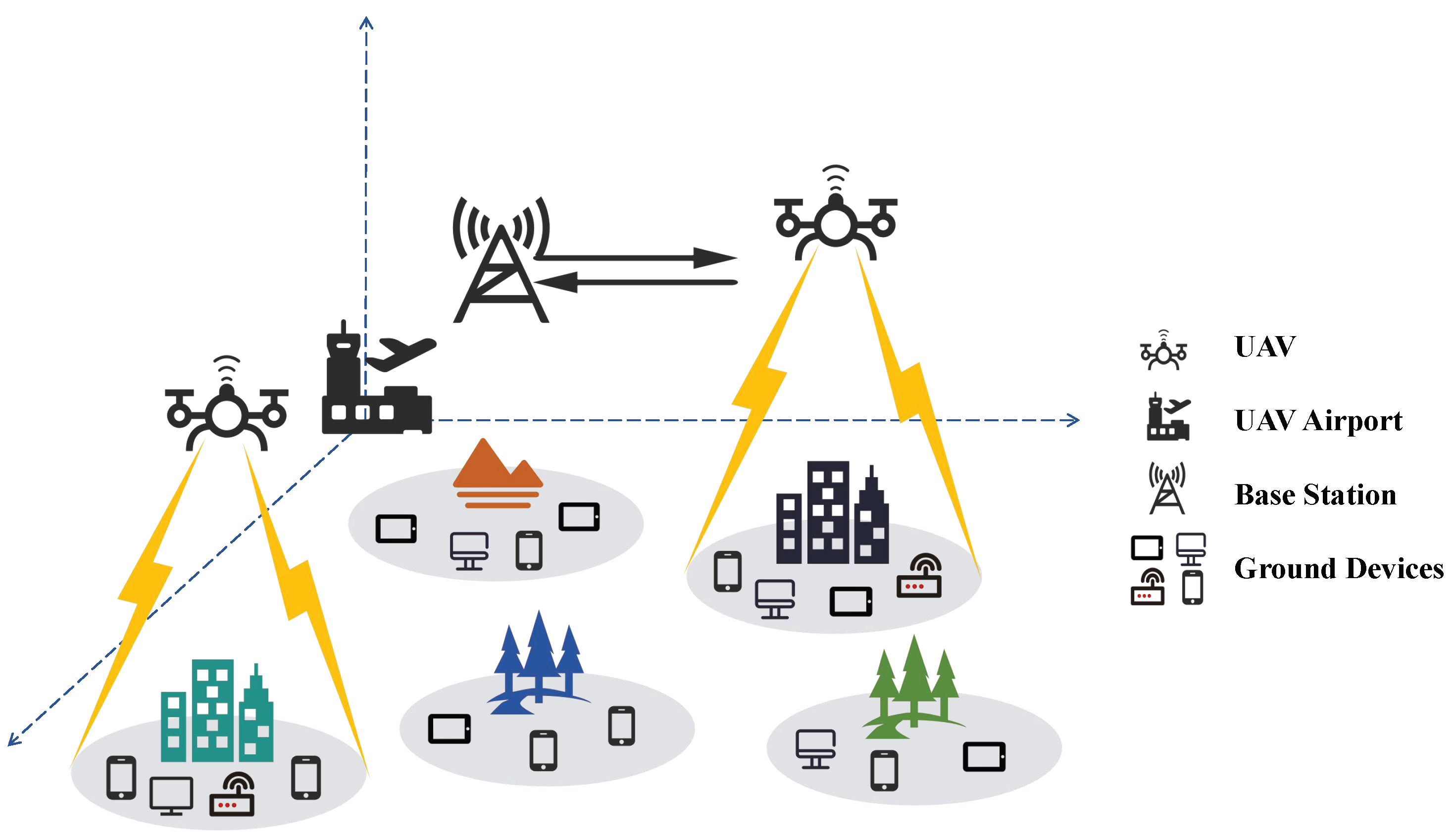
4], to adapt to different UAVs produced by different manufacturers, so that various types of UAVs can be applied to our solution. Meanwhile, compared to previous studies on static environmental systems, we consider the real-time constraints of tasks generated by GDs, which means that the UAVs can only serve tasks during the open time window of the task. Real-time tasks are widely present in real environments, such as a traffic intersection having a large amount of traffic flow during specific time periods and a company’s security system needing to monitor a certain area at specific times every day. We model the UAV routing problem with the above characteristics as a heterogeneous multi-traveling salesman routing problem with soft time constraints. Based on the NP-hard characteristics of the traveling salesman problem (TSP) and the MTSP, the heterogeneous multiple traveling salesman routing problem (HMTSRP) is also NP-hard. For UAV-assisted MEC, as shown in
Figure 1, the UAV departs from the airport, is deployed to a TA, that is an area where a large number of GDs are concentrated, interacts with the GD, and offloads tasks to the base station.
Providing high QoS for GDs in this model is a challenging issue: (a) A large number of dispersed GDs may make it difficult to determine the TAs, further leading to difficulties in selecting the optimal hovering position. (b) The heterogeneity of UAVs results in different flight capabilities, can lead to different results when different UAVs perform the same task combination, and significantly increase the solution space of the allocation strategy, then making the allocation of UAVs a difficult problem. (c) The time window constraint of a task defines the time it can be served, making it necessary to consider the time factor in UAV path planning. Only by scheduling the UAV to the task location within the time window can effective service be provided.
For the challenges mentioned above, we propose a heuristic UAV scheduling algorithm, referred to as HMUR, for the problem under study. The main contributions are as follows:
The task allocation and path planning problem of heterogeneous UAVs in MEC systems is modeled as a heterogeneous MTSP with soft time constraints, which is an NP-hard problem. This article proposes a solution called HMUR, which applies a two-stage heuristic algorithm to obtain an approximate optimal solution for improving the QoS.
Using the k-means clustering method to cluster the geographic coordinates of a large number of GDs solves the problem of too many IoT devices.
A method for calculating the fitness between heterogeneous UAVs with different flight capabilities and different task assignments is proposed to determine UAV allocation under resource constraints.
The time window constraint of the task is considered, and a heuristic method is used to formulate travel paths within the responsibility range of each UAV to achieve a higher QoS.
The rest of this paper is organized as follows.
Section 2 reviews the existing literature on the problem under study.
Section 3 proposes a modeling method for the system, and the problem is described and formulated.
Section 4 introduces the HMUR algorithm proposed in this paper.
Section 5 shows the experimental results, and
Section 6 provides the conclusion.
2. Related Work
In a MEC environment assisted by UAVs, many studies focus on path planning, trajectory optimization, task offloading strategies, and other aspects of UAVs. In this section, we discuss the achievements of existing research and analyze the focus that can be further studied.
The integration of energy-efficient routing protocols is a critical issue in prolonging the operating time of UAVs [
5]. The research focuses primarily on the following areas: Energy-Aware Routing Protocol (AODV [
6]): This protocol extends the overall network lifetime by prioritizing UAVs with a higher remaining energy to transmit data. Location-Aware Routing Protocol (GPSR [
7]): This protocol uses a greedy algorithm to select the node closest to the destination, thereby reducing data transmission distance and energy consumption. Cluster-Based Routing Protocol [
8]: This protocol extends the lifetime of the UAV network by periodically rotating the cluster heads to balance energy consumption. Hybrid Routing Protocol (ZRP [
9]): This protocol combines reactive and proactive routing mechanisms and dynamically selects the optimal routing strategy based on the distance between nodes and their energy status. Security is another critical concern in UAV-assisted MEC systems, where the integrity and confidentiality of data transmission must be maintained. Ensuring secure communication involves implementing robust encryption methods and secure communication protocols. Using advanced cryptographic techniques and secure transmission channels [
10,
11], the risk of data breaches and unauthorized access can be minimized.
Regarding the routing issue of a single UAV, Dariush Ebrahimi et al. [
12] proposed a reinforcement learning method to enable UAVs to autonomously locate and formulate trajectories within the task area; this work improved the positioning accuracy of multiple objects while considering time and path length to reduce UAV energy consumption. Liang Zhang et al. [
13] proposed an energy-efficient trajectory-optimization scheme for UAVs based on reinforcement learning; they jointly applied reinforcement learning methods to solve formulaic optimization problems, considering the average data rate, total energy consumption, and coverage fairness of IoT terminals to optimize the trajectory design of UAVs. Marceau Coupechoux et al. [
14] proposed an algorithm based on the Hamilton Jacobi equation to solve the single UAV-trajectory-optimization problem. This work finds the optimal trajectory to minimize costs while considering velocity and service traffic.
Many studies on routing and trajectory optimization for multiple UAVs have received attention. Kai Wang et al. [
15] proposed an iterative algorithm and made the first attempt to solve the collaborative path planning problem of multiple unmanned aerial vehicles. This work successfully transforms the problem into an integer linear programming problem by creating a new directed acyclic graph of the UAV state transition and proposes an iterative algorithm with a constant approximation ratio to solve this problem. Abhishek Bera et al. [
16] modeled the multi-UAV path planning problem as a capacitated single-depot vehicle-routing problem (CSDVRP) and proposed a routing-adjustment algorithm to optimize the trajectory of the UAVs; this algorithm considers the trade-off between different activation modes of IoT devices and UAV travel time. Yejun He et al. [
17] investigated a 3D multi-UAV trajectory optimization based on GDs selecting the target UAV for task computing; this algorithm theoretically derives and proves an optimal selection and uninstallation strategy for IoT devices. Hongyue Wu et al. [
18] proposed an improved tabu search algorithm under the background of UAV-assisted edge computing, focusing on path planning, while effectively optimizing the number of UAVs to speed up the unloading of computing tasks. Xiaohan Qiu et al. [
19] proposed an integrated host and content-centric routing mechanism that takes advantage of both mechanisms to address the issues of multi-UAV formation and integrated management. Hao Song et al. [
20] modeled the UAV network using the Poisson clustering process, divided the UAV network into multiple clusters, and designed an enhanced flood routing protocol based on random network coding and clustering to achieve efficient routing management of the UAV cluster network. Anna Gaydamaka et al. [
21] proposed a dynamic topology organization and maintenance method for UAV swarms and, based on this, designed advanced functions for dynamic cluster merging and separation, making it suitable for practical applications. Xutong Yang et al. [
22] proposed an adaptive routing scheme based on the Bodies mobile model to complete the task of efficient unmanned aerial vehicle (UAV) networks. They developed a biologically inspired Bodies-based Social Force Model (BSFM) and designed an adaptive UAV routing scheme to improve the communication performance of the UAV network while maintaining the topology. Mohammed Gharib et al. [
23] proposed a method based on linear programming modeling to address the problem of a self-organizing unmanned-aerial-vehicle-routing protocol to find the shortest path. Pengcheng Zhao et al. [
24] proposed a blockchain and deep Q-network (DQN) co-evolutionary routing (BDCoER) scheme for UAV networks, which completes the path co-evolution of the entire network based on each UAV training its own DQN model.
Many works on collision avoidance in UAV routing also have achieved accomplishments. Yu-Hsin Hsu et al. [
25] proposed a reinforcement learning method to help UAVs learn collision avoidance without prior knowledge of other UAV paths, while using optimization theory to find the shortest backward path for each UAV to ensure that the UAV collects data from all relevant IoT devices. Jinyu Fu et al. [
26] proposed a multi-layer projection clustering algorithm for multiple UAVs, developed a straight-line flight judgment to reduce the computational complexity of obstacle avoidance, and proposed an improved adaptive window probability roadmap algorithm to plan obstacle avoidance paths.
Table 1 shows a comparison between some related work and the work of this paper. The comparison of some related works with certain features of this paper, including the methods, the number of drones, and whether the drones are heterogeneous, reveals that many studies on multiple UAVs consider UAVs that are isomorphic, with identical battery capacity, signal transmission power, CPU operating speed, and so on. To better fit the actual situation and enrich the diversity of choices, we introduce the heterogeneity of UAVs in this study and then consider routing decisions for multiple UAVs. At the same time, we consider the real-time characteristics of the task based on the static MEC environment, to be closer to the real situation of UAV-assisted MEC.
3. System Model
In our proposed algorithm, each GD possesses an auxiliary calculation task. These tasks should be offloaded to the high-computing-ability base station (BS) by choosing proper UAVs as the relay devices, so as to optimize the QoS performance metrics (i.e., the number of tasks to be solved and the amount of offloaded workload). Several essential factors are included in the process, such as the number of tasks, the amount of offloaded workload, energy consumption, and the number of dispatched UAVs. We simulated this problem by establishing the following models: (a) scenario model, (b) communication model, (c) task-assisted model, and (d) energy consumption model.
The notations to be used are listed in Notations section.
3.1. Scenario Model
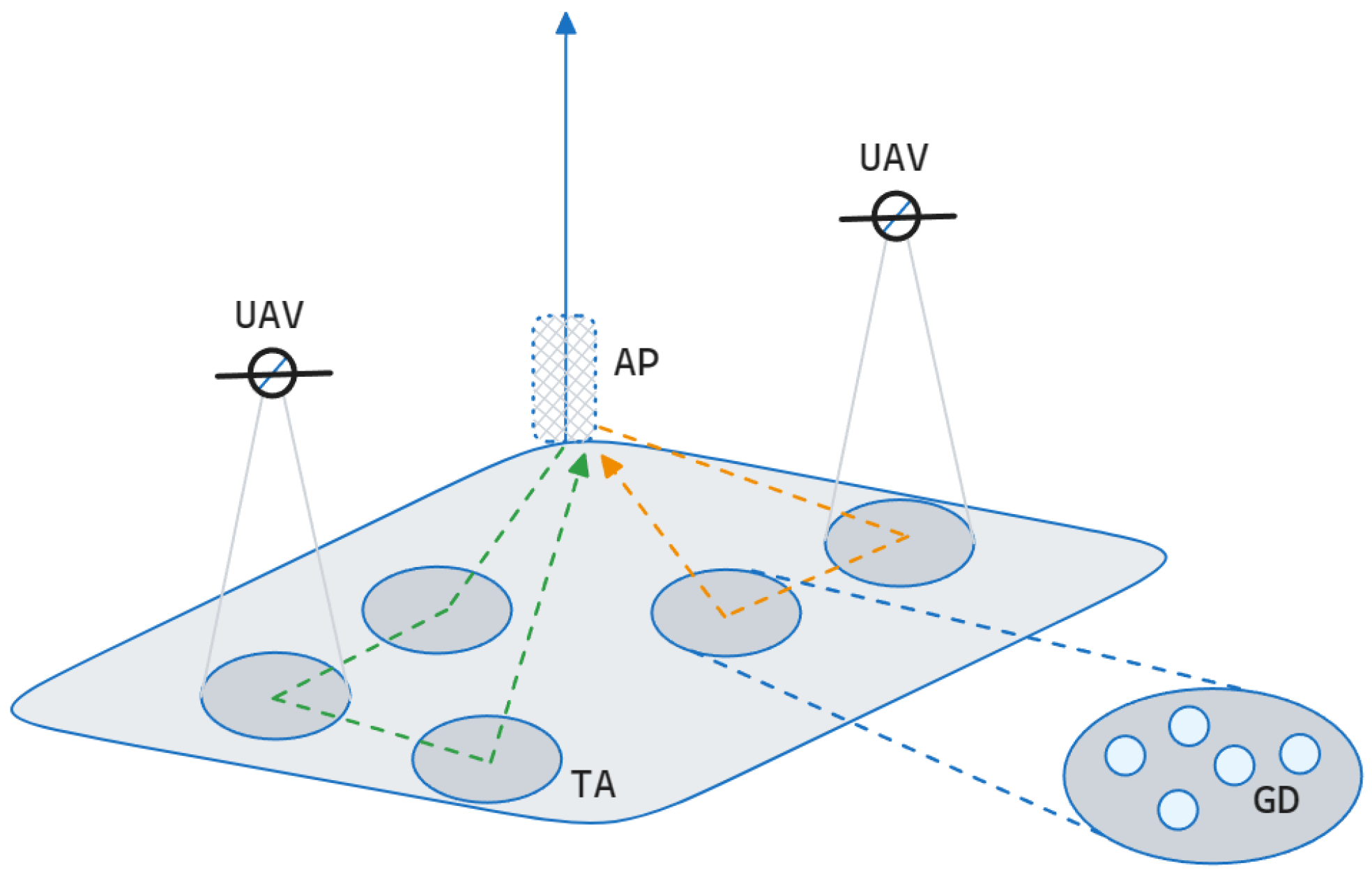
As illustrated in
Figure 2, we abstracted the entire environment into two parts: the air part and the ground part; GDs are fixed in the ground part and clustered as TAs, generating tasks waiting for UAV-assisted computation;
denotes a collection of
M GDs. Each GD is identified by a unique number, and a location is provided in the system. In this system, to simplify the computation, we assumed that each GD only generates one task within the same time interval, i.e.,
; task set
A corresponds one-to-one to GD set
D. Each task
is restricted by a real-time window
during which the task can only be performed.
represents the workload of task
.
Due to the large number of GDs, we need to identify TAs containing several GDs in the environment as a prerequisite for dispatching UAVs, i.e., denotes N TAs. Due to our simplified model, tasks correspond one-to-one to the GDs, and we can consider that each TA contains several tasks, i.e., indicates that TA contains a total of s tasks. For each TA, we determine a unique hover position to facilitate UAV positioning services. In addition, the BS and airport (AP) are also fixed on the ground, representing high-computing-power service base stations and UAV aprons, respectively.
In the air part, denotes K UAVs moving in the air. In this paper, task allocation and path planning are performed on them.
3.2. Communication Model
Based on many previous studies, such as [
2,
3,
16,
27,
28], we used the air-to-ground (ATG) [
2] LoS channel probability model to simulate the communication between the UAV and the GD. Let
and
denote the coordinates of UAV
and GD
at time
t; the Euclidean distance between them can be calculated as
The average path loss between UAV
and GD
can be expressed as a probability-averaged ATG-LOS model [
2,
16] into
where
and
are the pass loss for the LoS and Non-Line of Sight (NLoS) link and
and
denote the probabilities of LoS communication and NLoS communication, respectively.
and
are given as
where
is the carrier frequency,
c is the velocity of light, and
and
are the average additional loss for LoS and NLoS, respectively.
and
are given as
where
and
are the environmental constants, depending on the environmental condition in which the system is located.
is the elevation angle between GD
and UAV
. It is expressed in radians, as
Therefore, the data transfer rate (in bps) between GD
and UAV
is
According to the orthogonal frequency-division multiple access (OFDMA) communication [
2],
is the total channel bandwidth,
,
is the number of GDs serviced simultaneously,
is the transmission power of GD
, and
is the noise power.
Similarly, the transmission rate
of the offloaded data from the UAV to the BS is calculated by
where
is the transmission power of UAV
.
3.3. Task-Assisted Model
This work considers using UAVs as mobile relay points, which means that tasks can be offloaded from UAV relays to the BS for computation. As in many previous studies [
2,
29,
30], because its size is much smaller than the data size that must be offloaded, we ignored the delay in sending the data results from the BS back to the UAV and from the UAV back to the GD.
This work divides the working time of the entire system into several parts of a sufficiently small constant
of equal size and considers that the UAV is stationary within a time slot. Due to our communication being divided into two parts, GD to UAV and UAV to BS, we divided a time slot into the two same parts, i.e., UAV
assists task
in offloading data, and we have
, where
is the time that GD
offloads data to UAV
.
is the time that UAV
offloads data to BS. To ensure the complete processing of a portion of data within one time slot, i.e., the amount of data processed in both parts is the same, the time relationship between the two parts should meet
Based on the above, there are
At this point, the amount of data processed within one time slot, i.e., single time slot data processing speed, is represented as
The service duration of UAV
for GD
is
, where
is the amount of data that needs to be offloaded by
. At this point, the total duration of the UAV
hovering over TA
is
The total flight time of UAV from TA to TA is , where is the Euclidean distance between TAs and .
3.4. Energy Consumption Model
Due to the fact that the communication energy consumption of the UAVs is much lower than that of motion (including traveling and hovering), we ignore the communication energy consumption of the UAVs. Therefore, the energy consumption of UAV
executing tasks along the path
is expressed as
Based on the alternate fixed rotary wing UAV energy consumption calculation method [
2,
31] used, when UAV travels at velocity
v, the unit time flight energy consumption is
where
,
,
,
,
,
,
s, and
A are the aerodynamic parameters of the UAV. Specific definitions and settings can be found in
Table 2. Then, the total flight energy consumption of UAV
is measured by
3.5. Problem Formulation
To optimize the QoS with the restriction of energy consumption and the number of dispatched UAVs, a soft time constraint model named HMTSRP is proposed as follows. We define
Among these,
represents the total number of serviced tasks,
represents the total amount of offloaded data workload for serviced tasks, and
represents the amount of data offloaded by task
. Boolean variable
indicates whether task
is served by the UAV:
Therefore, we formulate a minimization problem as
(
21a) and (21b) are the optimization objectives, maximizing the total number of service tasks and data offloading, subject to the following: (21c) represents the battery capacity constraint for the UAVs; (21d) and (21e) represent the starting and ending points of the UAVs, which must be the AP; among these,
is the position of UAV
at time
n and
is the location of the AP; (21f) and (21g) represent that, for all TAs, there only exist one departure and one arrival for one UAV, respectively. The definition of Boolean variable
is as follows:
4. Problem Analysis and Solution Approach
In order to effectively allocate tasks to BSs for computation by relaying among multiple UAVs with different capacities, a three-step algorithm named HMUR is proposed in this paper. HMUR consists of three steps: (a) TA determination: establishing TAs for related GDs and determining the optimal hover positions of UAVs; (b) UAV allocation: assigning TAs to suitable UAVs; (c) subpath determination: determining the final task execution path for each UAV.
4.1. HMUR
Algorithm 1 shows the framework of HMUR. Throughout the entire process, HMUR first applies the k-means clustering algorithm to cluster the geographic coordinates of the GD and uses its clustering center as the optimal hover location. Secondly, HMUR executes Algorithm 2 for the UAV allocation to perform tasks. Finally, HMUR executes Algorithm 3 to determine the final subpath for each UAV.
In this process, we consider using energy consumption as a constraint for task partitioning in Algorithm 2 to ensure that at least one route for the UAV to be able to complete the designated task. Meanwhile, we use the QoS as an evaluation metric in Algorithm 3 to determine the final subpath, to optimize the service QoS as much as possible within the allowable range of energy consumption.
| Algorithm 1 HMUR algorithm. |
Input: D, A, and U;
Output: Final subpath set R;
- 1:
k-means clustering algorithm generates B from D and determines the optimal hover position - 2:
Algorithm 2 determines UAV allocation for B - 3:
Algorithm 3 determines the final subpath set R - 4:
return Final subpath set R
|
| Algorithm 2 UAV allocation. |
Input: B, U;
Output: Allocation set K for UAV;
- 1:
Generate graph G from B - 2:
Generate minimum spanning tree from G - 3:
Generate set of odd degree vertices O from - 4:
Find minimum weight matching M from O - 5:
Merge T and M to generate Eulerian circuit - 6:
Generate Hamiltonian circuit from - 7:
- 8:
while do - 9:
- 10:
for do - 11:
Simulate travel from , and generate - 12:
Record - 13:
end for - 14:
Choose with for n TAs that it covered - 15:
Generate , and allocate for - 16:
Add to K - 17:
Remove from U - 18:
- 19:
end while - 20:
return Allocation set K
|
| Algorithm 3 Subpath determination. |
Input: U, K;
Output: Final subpath set R;
- 1:
for
do - 2:
for all do - 3:
- 4:
end for - 5:
- 6:
while do - 7:
for all
do - 8:
if then - 9:
Calculate - 10:
end if - 11:
end for - 12:
Choose TA with the highest as the target - 13:
- 14:
- 15:
Add to queue - 16:
Delete from - 17:
end while - 18:
if Energy consumption of exceeds the maximum energy consumption of then - 19:
predicted path generated by Algorithm 2 - 20:
end if - 21:
Add to set R - 22:
end for - 23:
return R
|
4.2. TA Determination
Since there are numerous GDs in the MEC environment, it is not realistic to assign one UAV to each GD for auxiliary computation. Thus, GDs with close geographical coordinates are aggregated into TAs, which are served by UAVs within certain time periods. Under constant environmental factors, the data transmission rate is mainly related to the distance
between UAV
and GD
. Obviously, the smaller
is, the higher the transmission rate. Therefore, in TA
, the optimal hover location is the position with the smallest distance from all GDs, and we formulate this problem as follows:
The k-means clustering algorithm [
16,
32] is adopted here to establish clusters (i.e., TAs) and determine the cluster centers (i.e., the optimal hover positions of UAVs). The assignment of a GD to a nearby TA is iteratively updated by k-means until convergence. Then, the point with the minimum sum of distances from all the other GDs within one TA is considered as the optimal hover position.
4.3. UAV Allocation
After obtaining the TAs, each UAV will be allocated to several TAs. Let
be the set of allocations of
K UAVs, of which each element
represents a mapping between
and the TA set
. Then, this paper takes the battery capacity carried by the UAV as a constraint and considers maximizing resource utilization for
to execute tasks in
. To ensure the continuity of UAV routes, a partitioning method is proposed by adding breakpoints to a single TSP path to partition TAs. Based on the Christofides approximation algorithm [
16], an advanced fitness function
is introduced to efficiently evaluate the allocation results in TAs of different heterogeneous UAVs.
Algorithm 2 employs the Christofides algorithm to obtain an approximate solution for the traveling salesman problem (TSP). This approach utilizes a minimum spanning tree, perfect matching, an Eulerian circuit, and a Hamiltonian circuit from graph theory to provide a suboptimal solution. As mentioned in previous research [
16], the performance ratio of the Christofides algorithm does not exceed 1.5 compared to the optimal solution, and it is a constructive solution that can be solved within polynomial time.
As shown in Algorithm 2, after creating a complete TSP path
by lines 1 to 6, some breakpoints are inserted to truncate the path into several predicted paths: when UAV
travels along
(denoting a TA sequence) and consumes energy during flight and mission execution; when a UAV finds that its energy consumption cannot reach the next TA and then returns to the AP, it will return to the AP and represent the TAs’ path that has performed for the task as
. If
travels along the route
, the fitness can be designed as
where
represents the energy consumption of
during task execution,
represents the total energy consumption of this travel path, and
represents the maximum battery capacity of
. So, the effective energy consumption rate
. Due to the heterogeneity among UAVs, different UAVs executing tasks from the same route may insert virtual points into different positions (i.e., returning to the AP from different TA endpoints), resulting in different
.
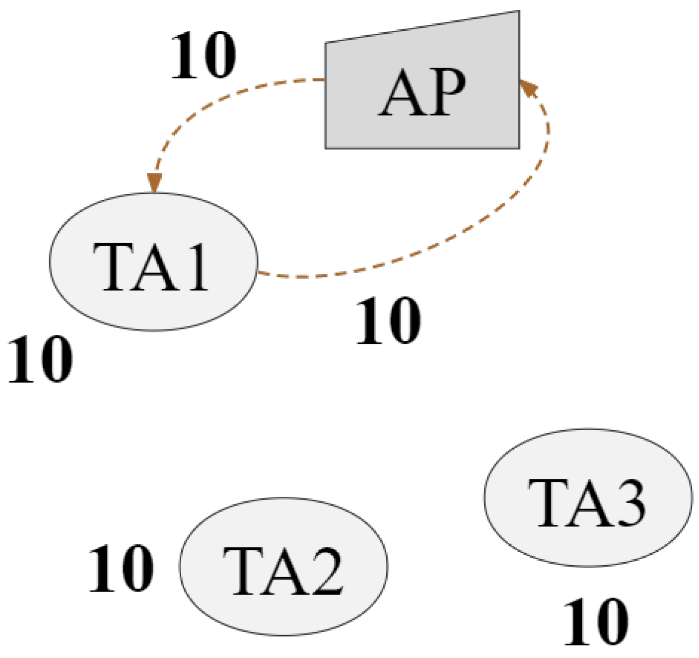
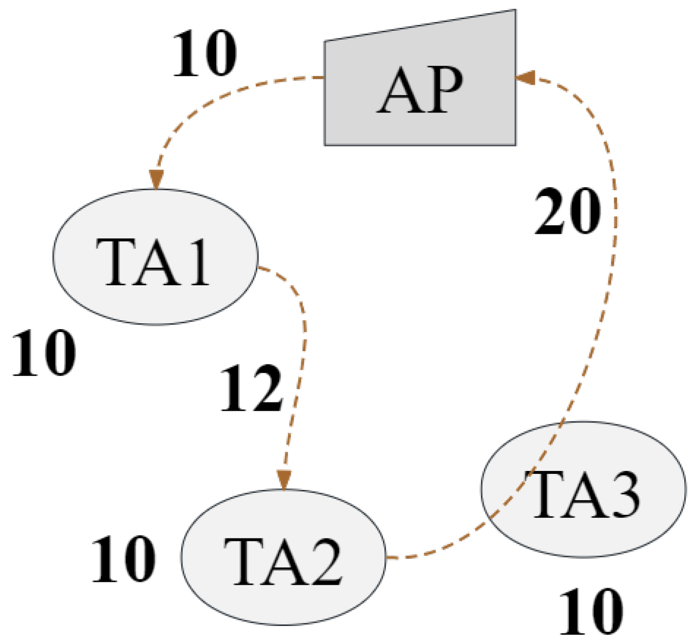
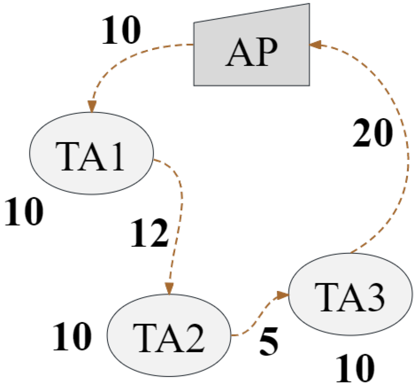
An example of Algorithm 2 is illustrated in
Figure 3,
Figure 4 and
Figure 5. Assume that travel consumption is an integer, and temporarily assume that the hover consumption of UAV at each concerned TA is 10, i.e., the energy consumption occurring when a UAV resolves tasks at a specific TA. The UAV executes tasks in the order of
, and the energy consumption rate of each situation is
,
, and
, respectively. To some extent, the higher
, the more tasks can be solved with the same energy consumption, further indicating that we can obtain a better solution by organizing the dispatch of heterogeneous UAVs. In addition, the second item of (
24) with a gravity control factor
is used to control the resource utilization of UAVs, aiming to maximize the utilization of the total battery resource carried by the UAV.
4.4. Subpath Determination
After obtaining the allocation set for different UAVs, HMUR determines the final task execution path for each UAV. In this section, we take into account the real-time window constraint of tasks.
We process UAV allocation options
K and rearrange the routing path within the energy consumption limitation. According to the predicted results of Algorithm 2, it can be seen that, among all the tasks the UAV is responsible for, each UAV has at least one route that can complete all tasks. Specifically, in the selection of the allocation of
, the UAV
starts from the AP, predicts the arrival time of the task points in
that have not been traversed, and calculates the score function for the selected TA. The score function is formulated as follows:
where
is the number of tasks that open the window upon arrival,
is the energy consumption for flying from the previous point to
, and
is total workload of data expected to be offloaded in
. The UAV selects the TA with the highest
and travels to TA
to complete as many tasks as possible during the window period. The optimization in this section focuses on adapting to the real-time window factor of the task, sacrificing some energy consumption to achieve greater QoS, and to some extent, neglecting energy consumption control. Therefore, during the adjustment process, there may be situations where the total energy consumption exceeds the maximum energy consumption of the UAV. In response to this situation, we abandon the path rearrangement and use the predicted path generated by Algorithm 2 as the final routing path.
This paragraph analyzes the time complexity of the algorithm to ensure the real-time applicability of the entire system. As previously mentioned, under the environment of n TAs and n UAVs, the Christofides algorithm can solve problems within polynomial time with a complexity of . Additionally, lines 8-19 of Algorithm 2 iterate through each path divided by the Christofides algorithm and traverse m UAVs in each path, with a time complexity strictly less than . Moreover, after initialization, Algorithm 3 enters a double loop, which simulates the value of the UAVs reaching different TAs on each subpath, with a time complexity of . Consequently, HMUR can solve the problem within polynomial time.
6. Conclusions and Future Work
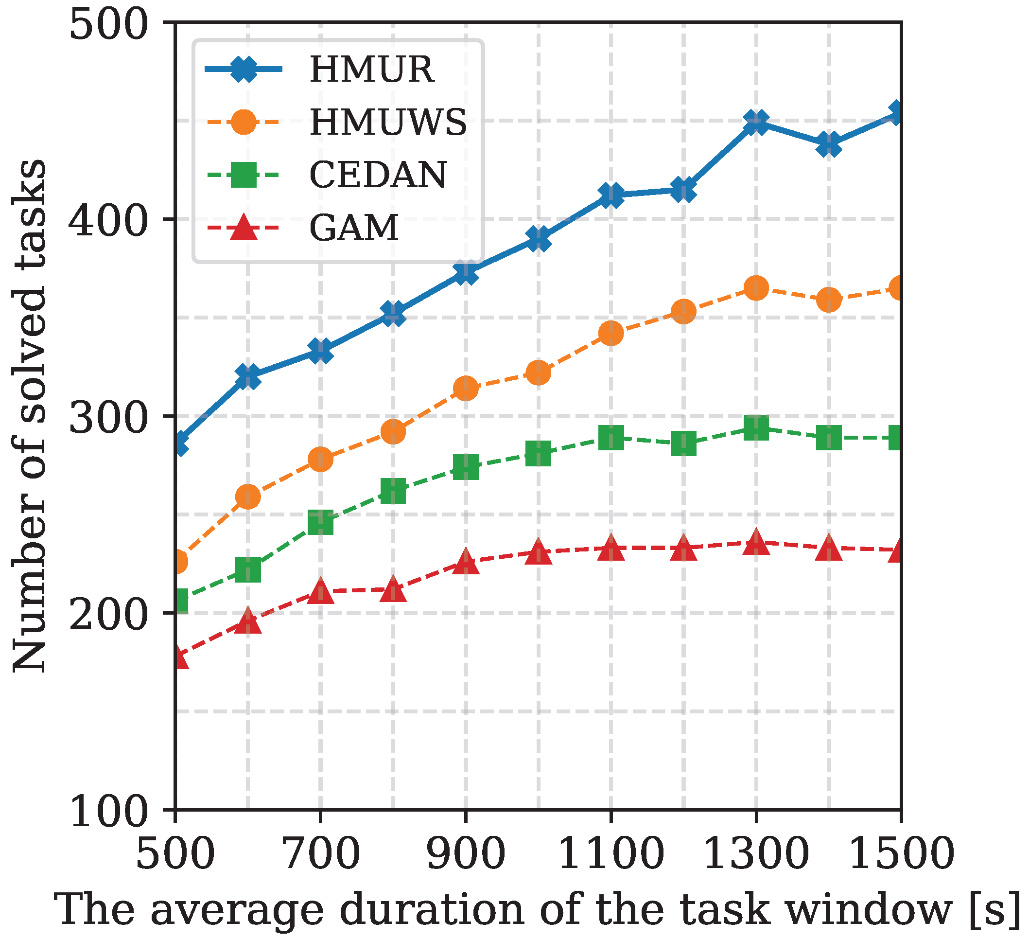
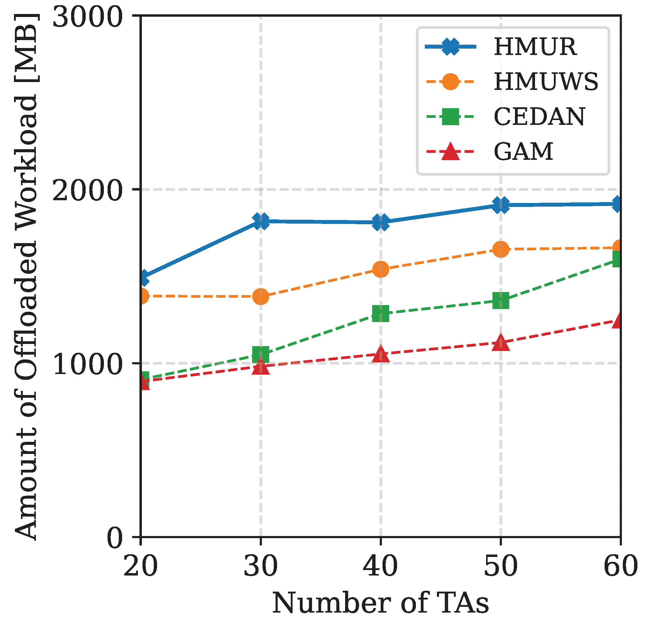
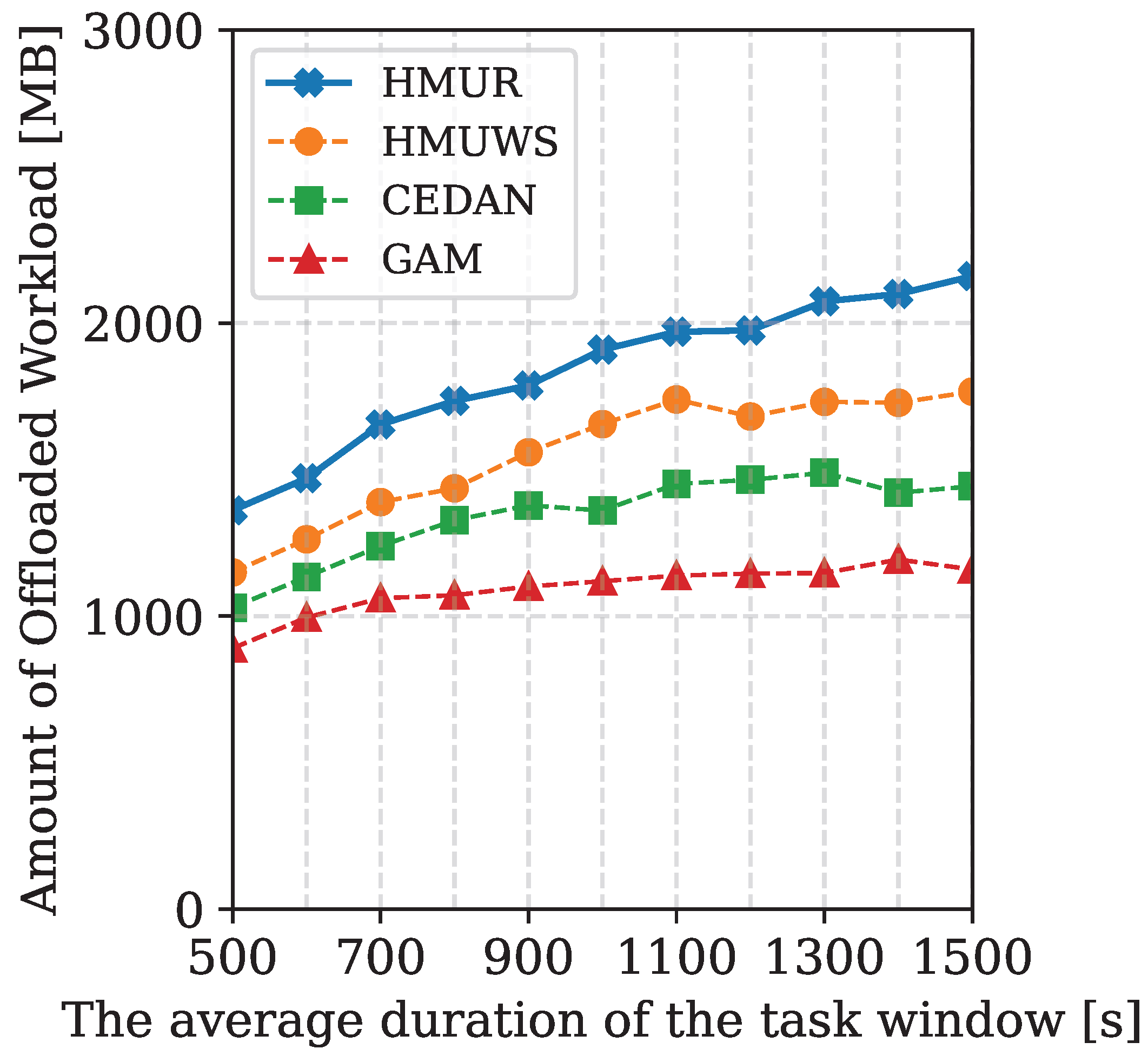
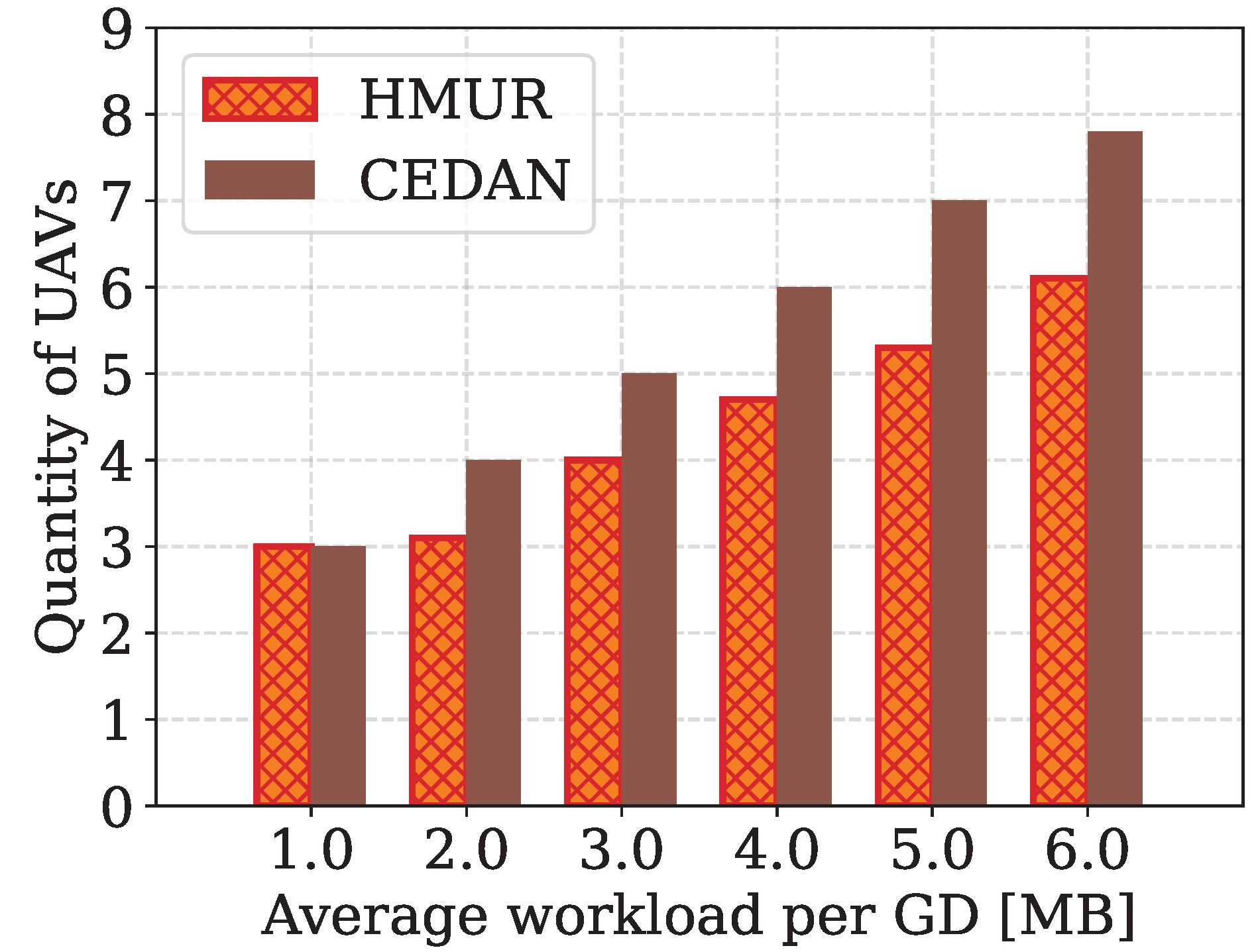
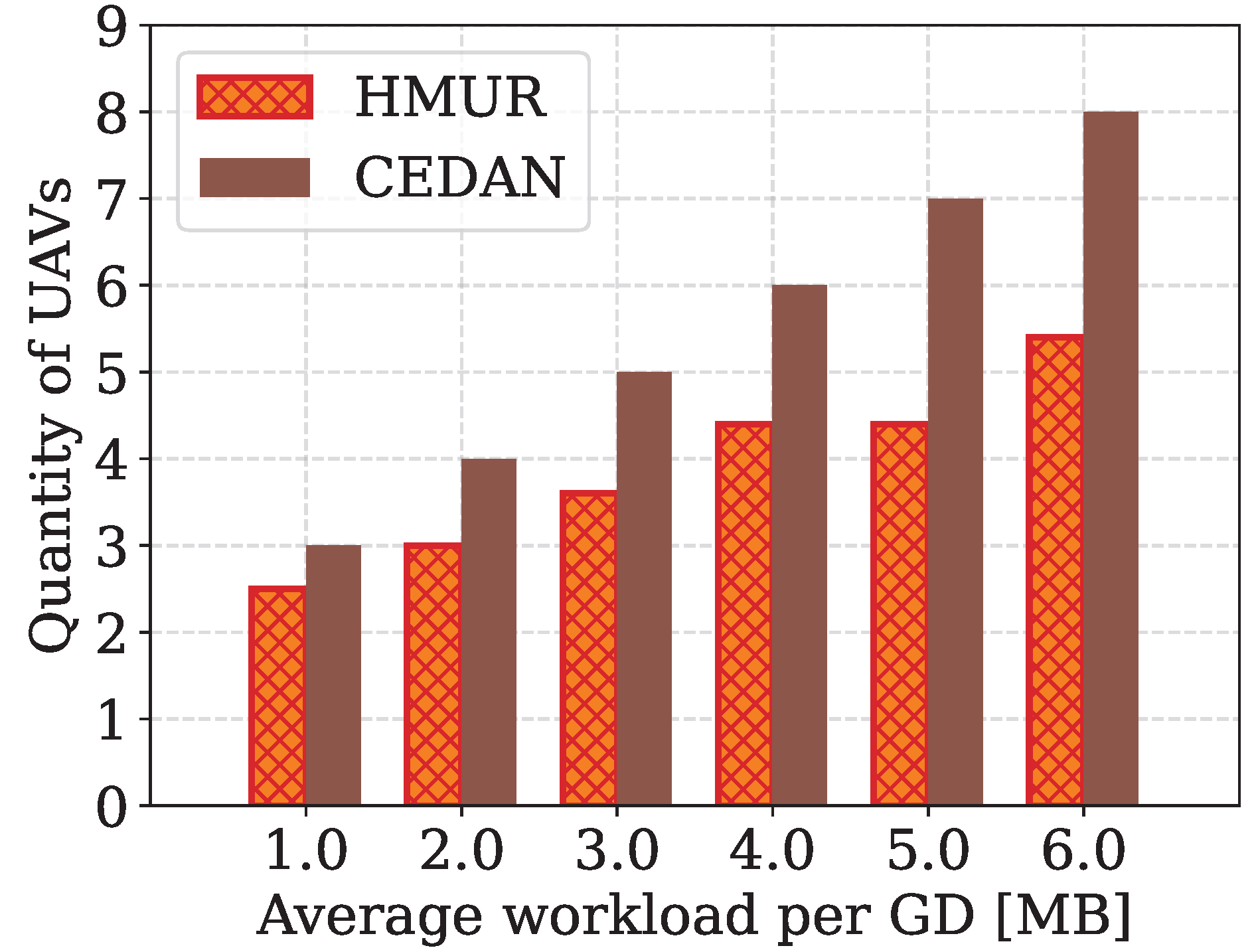
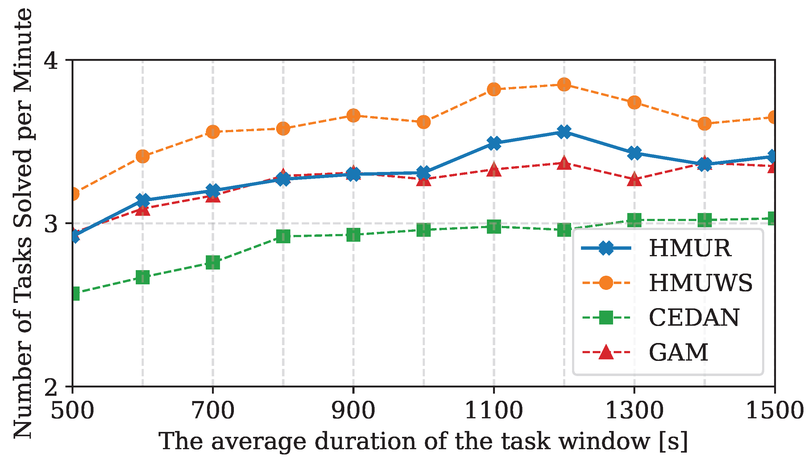
In this paper, a multi-UAV routing algorithm named HMUR is proposed for the UAV-assisted MEC problem. Instead of isomorphic UAVs as commonly considered in the literature, we also took into account the heterogeneity of UAVs and the real-time characteristics of the task. An effective fitness measurement is defined to match the UAVs and different routing paths under certain energy constraints. A score function is designed to determine the final route with the highest QoS. An extensive comparison of the proposed algorithm is performed against the best existing approaches. The experimental results show that the proposed method is superior to the best existing algorithms on multiple metrics. We demonstrated the effectiveness of the algorithm through experiments divided into four parts, which collectively evaluated the performance of the service based on the number of tasks completed, the volume of data offloaded, the efficiency of task resolution, and the number of UAVs used. The volume of data offloaded is correlated with the number of tasks completed. Through the HMUR algorithm, heterogeneous UAVs are appropriately allocated in the UAV allocation segment and tasks are reorganized in the subpath determination segment to ensure that more tasks are within their window period when the UAV reaches the task area. Furthermore, since the fitness function considers the ratios of to (reflecting the effective energy consumption of UAVs) and to (reflecting UAV battery utilization), it ensures that the energy of each UAV is efficiently used, thereby indirectly reducing the number of UAV deployments.
Future research avenues involve the consideration of the improvement of the proposed framework. For example, more UAV attributes such as output power, battery weight, bandwidth, and flight speed can be introduced as a UAV-type selection mechanism. It also seems worthwhile to apply the proposed algorithm with some heuristic offloading solutions for further improvement. Meanwhile, future work could consider replacing FDMA with communication methods such as TDMA and LoRaWAN to achieve new effects. At the same time, we will explore the integration of machine learning techniques and reinforcement learning for routing to adaptively allocate tasks based on historical data, improving the efficiency and responsiveness of our system. Additionally, we aim to develop a user-friendly tool for easy implementation and deployment of our algorithm in various MEC environments, enhancing user adoption and practicality.


