Article

Autonomous UAV Safety Oriented Situation Monitoring and Evaluation System

School of Electronics and Information, Northwestern Polytechnic University, Xi’an 710129, China
*
Authors to whom correspondence should be addressed.
Drones 2024, 8(7), 308; https://doi.org/10.3390/drones8070308
Submission received: 5 June 2024 / Revised: 2 July 2024 / Accepted: 3 July 2024 / Published: 9 July 2024
(This article belongs to the Special Issue UAV-Assisted Mobile Wireless Networks and Applications)

Abstract

:
In this paper, a LabVIEW-based online monitoring and safety evaluation system for UAVs is designed to address the deficiencies in UAV flight state parameter monitoring and safety evaluation. The system consists of a lower unit for UAV recording and an upper unit on the ground. The lower unit collects and detects flight data and connects to the upper unit through a wireless digital transmission module via a serial port. The upper unit receives the data and carries out the monitoring and safety situation evaluation of the UAV. The lower unit of the system adopts multi-sensors to collect UAV navigation information in real time to achieve flight detection, while the upper unit adopts LabVIEW to design the UAV online monitoring and safety situation prediction system, enabling monitoring and safety situation prediction during UAV navigation. The test results show that the system can detect and comprehensively display the navigation information of the UAV in real time, and realize the safety evaluation and warning function of the UAV.

Graphical Abstract

1. Introduction

As a kind of flying machine, unmanned aerial vehicles (UAVs) have undergone decades of development since their invention in the 1940s. They have now been integrated into all walks of national production and life [1,2,3,4], and have been widely used in many fields such as military, civil, and commercial applications. On the military side, they perform a variety of military tasks in war, including reconnaissance, target location, signal intelligence searching, defense, and the control of fire decoys, and other forms of real-time intelligence gathering [5,6,7,8,9]. On the civilian side, UAVs can complete high-altitude and high-risk work such as courier transport, pesticide spraying, and antenna inspection [10,11,12,13,14]. In the commercial sector, the use of UAV aerial photography can be used to enhance the viewing value of film and television productions, as well as providing other commercial functions [15].
With the rapid development of the aircraft industry and the widespread application of UAVs, people have put forward higher requirements for the quality, flight safety, and stability of UAVs. The issue of aircraft flight safety has received widespread attention and is increasingly prominent. Improving the technical performance and flight reliability of UAVs has always been a frontier and hot topic in the field of UAV scientific research [16]. Setting up a monitoring system for UAVs is a commonly used method to monitor the safety of UAV airframes. The monitoring system can significantly enhance the safety of the equipment, and currently, most UAV ground stations are used to achieve the real-time monitoring and navigation control of UAVs. The research in this field by domestic and foreign scholars is mainly as follows.
In the study of monitoring systems, many scholars have designed monitoring systems in different fields to achieve the monitoring of safety data on specific targets. Some research has applied artificial intelligence-based WSN technology to home security monitoring systems, effectively improving the accuracy of home security monitoring. This study represents an important application of security monitoring in the field of home security [17]. Other research has designed a novel cloud storage-oriented sports fitness monitoring system, which effectively improves the accuracy and response speed of sports fitness monitoring results and makes the monitoring results more comprehensive. This research applies monitoring techniques and pattern recognition to the field of table tennis [18]. Some research combines electro-method exploration with geological disaster monitoring to develop an improved geological disaster monitoring system, providing adequate technical support for the monitoring of geological hazards through the use of detection technologies [19]. Additional research has established a detection system for athletes’ training to monitor the whole process of sports training [20]. Other research addresses the problem that traditional grid monitoring methods are difficult to accurately detect grid faults and builds a smart grid fault monitoring system using the Internet of Things (IoT) and Geographic Information System (GIS) to improve the effectiveness of fault monitoring [21]. Some research has designed and developed a wireless sensor network data visualization system [22]. A real-time urban air quality monitoring system based on wireless sensor networks was designed to solve the problems of high cost and the inability of simultaneous multi-point real-time online monitoring associated with traditional air quality monitoring methods that combine manual sampling and laboratory analysis. Some research has proposed a novel remote monitoring system for digital agricultural greenhouse inspection [23]. The remote monitoring system for digital agricultural greenhouses is deployed online using IoT technology to fully ensure the quality and timeliness of the remote monitoring. Other research has studied multi-sensor network estimation of mine water quality, water quantity monitoring equipment, and mine water IoT [24]. A mine water IoT monitoring system for wireless monitoring of water quantity and quality was designed, and an experimental platform for wireless monitoring of mine water was developed. Some research has designed a monitoring system for a specific sport, which can provide a basis for the collection of movement information of table tennis players and for subsequent behavioral analysis [25]. Other research has proposed a real-time sensor-based risk assessment method to enhance UAV flight safety [26]. By streaming UAV sensor data to the rule engine in real time, the method is able to calculate the risk level of the UAV during flight, thus providing a real-time risk reference for the pilot. Some research has been conducted to predict flight paths during UAV flight and to improve basic safety assessment studies for autonomous flying UAVs [27].
All of the above literature has established safety monitoring systems for different safety scenarios to ensure the normal operation of the system. However, research on the detection of UAV flight parameters and state parameters, as well as the estimation of safety posture, is still weak or insufficient to a certain extent. Based on the needs in the field of UAV safety monitoring and evaluation, we designed a LabVIEW-based online monitoring and evaluation system for UAV safety.
The main contributions and innovations are as follows:
  • A UAV on-board data measurement system, which can monitor UAV on-board data, was established.
  • A UAV monitoring system based on LabVIEW, which can display UAV data in real-time, was established.
  • An autonomous safety evaluation system for UAVs, which can evaluate the safety posture of UAVs according to their current flight status, was established.
  • The established LabVIEW-based online monitoring and evaluation system for UAV safety can provide a flight guarantee for autonomous flying UAVs.
The rest of the paper is organized as follows. The first part is the overall programmed design of the UAV, describing the main hardware and framework of the system. The second part is the software design, describing the system’s upper and lower components and principles. The third part is the design of the autonomous safety evaluation system, which uses UAV on-board information to achieve safety posture assessment of the UAV itself. The fourth part is the system test and analysis results, which test and analyze the UAV monitoring system as well as the safety posture assessment system. Finally, the fifth part, the conclusion, summarizes the full paper.

2. Overall Design of Online Monitoring System

The block diagram of the monitoring system structure is shown in Figure 1. The monitoring system consists of a lower unit, a transmission system, and an upper unit. The lower unit is composed of a microcontroller minimum system, power supply module, power module, GPS positioning module, flight altitude measurement module, attitude detection module, and main control module; the transmission module is built by 3DR wireless digital transmission module, which provides a wireless communication channel for the wireless communication between the upper unit and the lower unit; and the upper unit is built by LabVIEW to monitor the system, which realizes the monitoring, controlling, and data recording functions of the UAV during the flight. The upper computer is built by LabVIEW to achieve the monitoring, control, and data recording functions during the UAV flight.

2.1. Microcontroller Minimal System

The microcontroller minimum system mainly includes a power supply circuit, a crystal clock circuit, a reset circuit, and an STM32F427 microcontroller. The power supply circuit provides DC power for the normal operation of the lower computer, which is powered by a lithium battery. The clock circuit provides timing signals for the microcontroller’s work. The reset circuit ensures that the microcontroller can perform a reset operation when it is malfunctioning, so as to make the microcontroller return to normal operation. The STM32F427 microcontroller processes and acquires information, and uploads it to the upper computer through the wireless transmission module.

2.2. Power Supply Module

The power supply module consists of a battery pack, a voltage regulator module, and a detection and alarm module. The battery pack provides the system power supply, with a capacity of 5200 mAh. It consists of three Li-ion batteries connected in series, providing a voltage supply ranging from 11.1 V to 12.6 V. The voltage regulator module stabilizes the power supply voltage at 5 V to power the UAV. The voltage detection and alarm module detects the battery power in real time and initiates a low-battery alarm when the power is lower than the set threshold.

2.3. Power Module

The power module provides the power for UAV flight, which consists of a F450 frame module, 9450 propeller module, Sunny sky brushless motor module, and X-Rotor 30A ESC module. The symmetrical motor axis of F450 frame is 450 mm. the motor module is controlled by a PWM wave sent from the STM32F427 master control system, which drives the propeller drive and generates the upward force. The ESC module uses a three-phase bridge inverter circuit to adjust the voltage and current of the drive motor to ensure normal motor operation.

2.4. GPS Positioning Module

The GPS positioning module collects and measures the latitude and longitude information of the UAV itself, locates the position of the UAV in the plane map, and sends the data to the host computer for display. The GPS module of the UAV calculates the relative position of the UAV and the GPS satellite based on the real-time reception of the radio signals continuously sent by the GPS satellite in the air, and ultimately determines the latitude and longitude of the UAV by receiving multiple GPS satellite signals. The GPS module cooperates with the accelerometer and gyroscope modules of the attitude checking system to realize the monitoring of the UAV’s flight position and attitude as well as the navigation of autonomous flight.

2.5. Altitude Measurement Module

The flight altitude measurement system uses the LPS331 barometer module to measure the atmospheric pressure of the current flight environment of the UAV. The relationship between atmospheric pressure P and altitude h is shown in the equation.
P = P 0 × 1 L h T 0 g M R L
In Formula (1), P 0 is the standard atmospheric pressure at sea level, which is the following: H is the altitude; L is the rate of temperature decrease, about 0.0065 K/m in dry air; T0 is the sea level standard temperature; G is the acceleration of gravity on the earth’s surface, about 9.8 m/s2; M is molar mass, about 0.0289644 kg/mol; R is the universal gas constant, about 8.31447.
The formula for calculating altitude can be obtained, as shown in Equation (2).
h = 4.43 × 10 4 × ( 1 9.87 × 10 6 P ) 1 5.256
The altitude of the UAV before take-off is taken as the initial altitude h0 of the UAV, and the difference between the altitude measured during UAV flight and the initial altitude is the flight altitude of the UAV. That is, as shown in Formula (3).
H t = h t h 0
In Formula (3), h(t) is the altitude measured during UAV flight, h0 is the altitude measured before UAV take-off, and H(t) is the real-time flight altitude measured by the UAV.

2.6. Attitude Detection Module

The UAV attitude detection module detects the spatial attitude data of the UAV through the MPU6050 gyroscope and solves the Euler angle formed by the UAV in three-dimensional space with the coordinate axes using the quaternion method. The Euler angle solving process is as follows.
Firstly, the gyroscope is initialized and the initial spatial coordinate system of the gyroscope is calibrated; secondly, the data of the gyroscope device are collected, and the quaternion differential equations are solved according to the data; thirdly, the accelerometer data are collected, and the complementary filtering is performed to reduce the error according to the accelerometer and the gyroscope data; and lastly, the Euler’s angle of the UAV’s current attitude is solved.

2.7. Wireless Transmission Module

The wireless transmission module transmits the on-board data information to the upper computer for comprehensive display, realizing online monitoring of UAV flight. The 3DR wireless data transmission module is used to connect the upper and lower units of the UAV, and the on-board sensing data of the UAV are transmitted by serial port for wireless data transmission; the receiving module on the PC side receives the wireless data signals sent by the transmitting module and then decodes them, and the decoded data are output from the serial port.

3. System Software Design

3.1. Functional Block Diagram of the Lower Computer Software

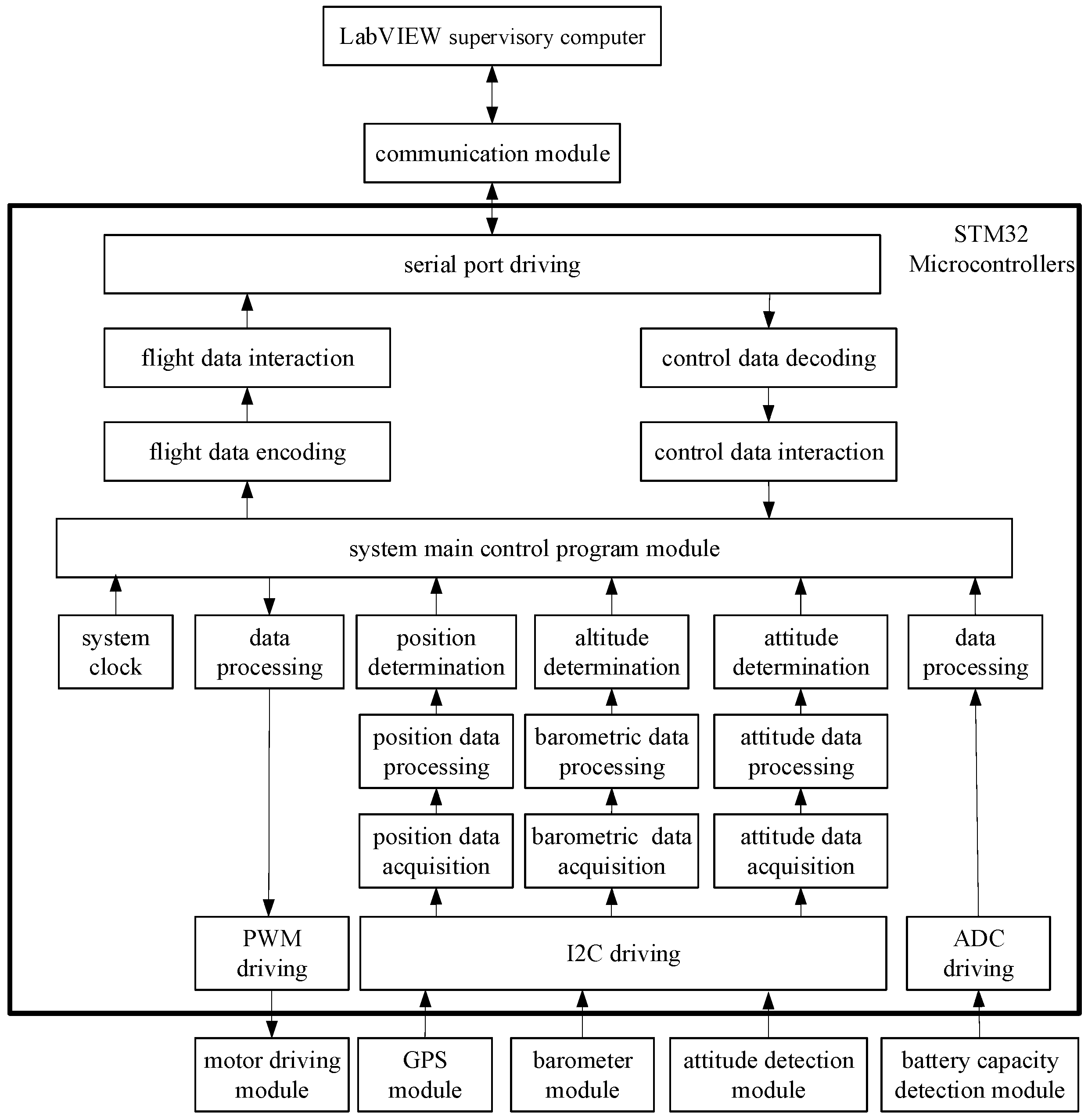
The overall design of the functional block diagram of the lower computer software is shown in Figure 2. The lower computer software programmer of the system is mainly divided into five parts: motor drive subroutine, GPS positioning subroutine, altitude measurement subroutine, attitude detection subroutine, and power detection subroutine.
The motor driver monitors the PWM signal output from the processor and adjusts the motor speed to control the UAV to complete the corresponding action. The GPS positioning subroutine completes the positioning of the flight position and data, and transmits them through the serial port. The altitude measurement subroutine detects the real-time air pressure of the UAV, calculates the altitude at which the UAV is located, and uploads it. The attitude detection subroutine solves the linear and angular motion of the UAV in space through the output of the three-axis accelerometer and three-axis gyroscope, realizes the solving of the UAV’s attitude information, and transmits it through the serial port. The power detection subroutine monitors the UAV’s battery power in real time, and when the battery power is lower than the set threshold, it controls the buzzer alarm and uploads the alarm signal to the supercomputer. All of the above information is uploaded to the LabVIEW host computer through the wireless digital transmission module to realize online monitoring of UAV flight.

3.2. Flowchart of the Main Programmer of the Front Panel of the Host Computer

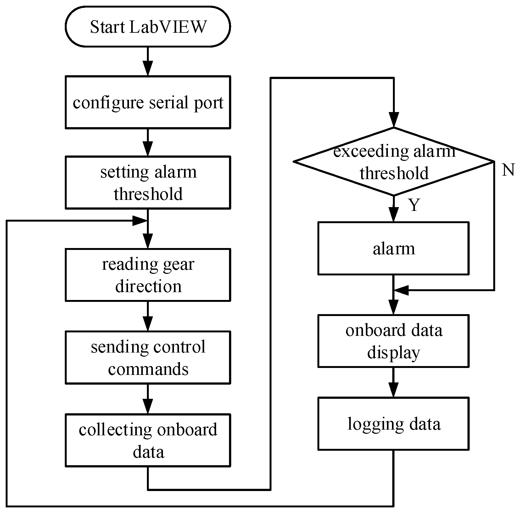
The upper computer uses LabVIEW to design the monitoring system, and the main flow chart of the front panel is shown in Figure 3.
The UAV flight online monitoring system upper front panel subroutine consists of the following steps.
Step 1 Start LabVIEW and configure the serial port.
Step 2 Set alarm thresholds, including distance, speed, RPM, and power, which can be adjusted during the running of the programmer.
Step 3 Read the throttle gear and the direction of motion, which can be adjusted during the flight of the UAV.
Step 4 Sends control instructions to the UAV with respect to the throttle gear position, so that the UAV completes the corresponding action in accordance with the control instructions.
Step 5 Collects on-board data, including air pressure, position, attitude, and power data, and solves data such as altitude, distance, hourly speed, and rotational speed of the UAV.
Step 6 Determines whether the on-board data exceeds the alarm threshold, and enters the next session if the alarm threshold is not exceeded; if the signal exceeds the alarm threshold, the alarm indicator lights up, prompting an alarm.
Step 7 Visualize the UAV flight data.
Step 8 Record the UAV flight data.
Step 9 The system enters the next cycle.

3.3. Monitoring System Front Panel Design

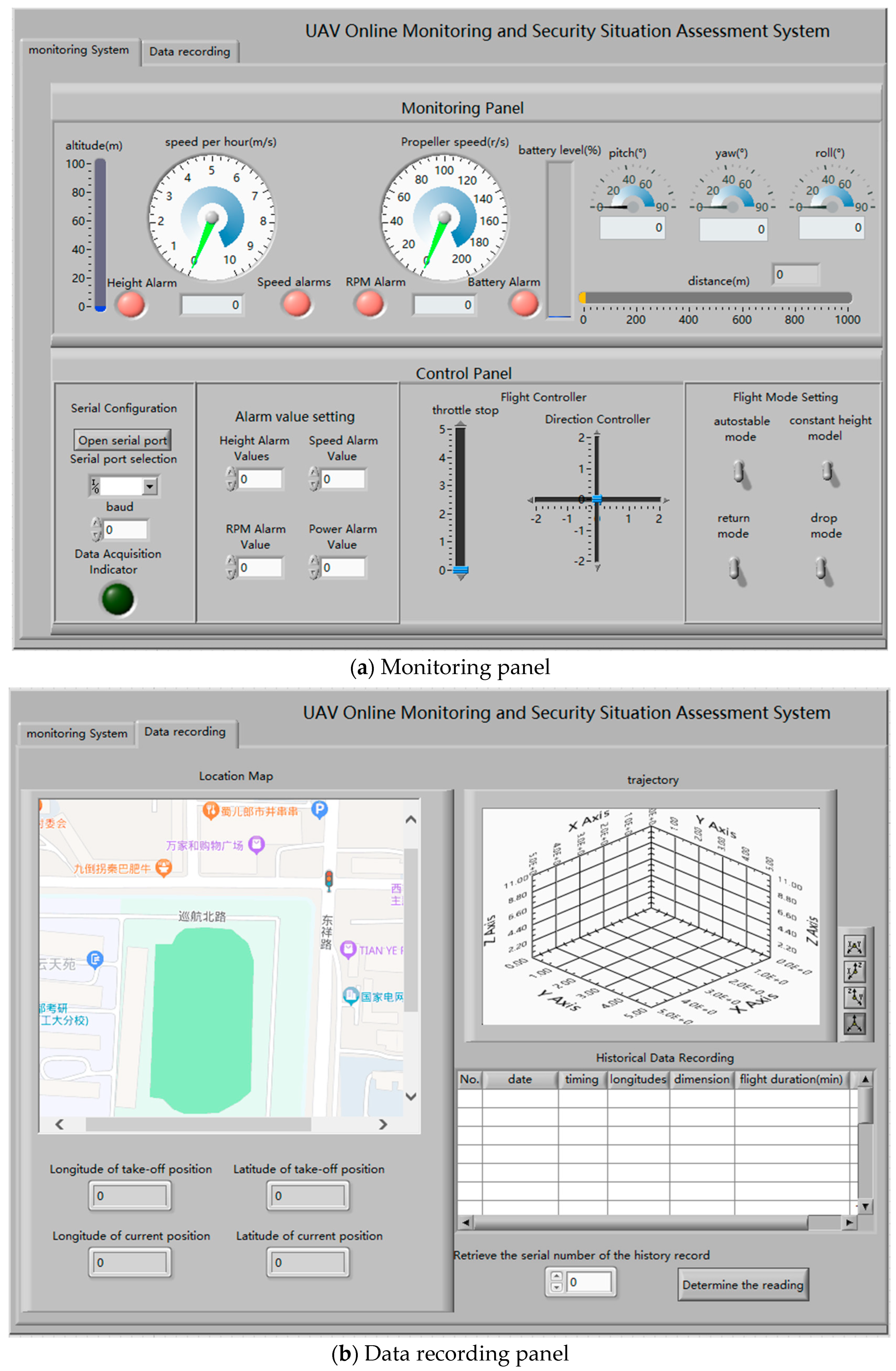
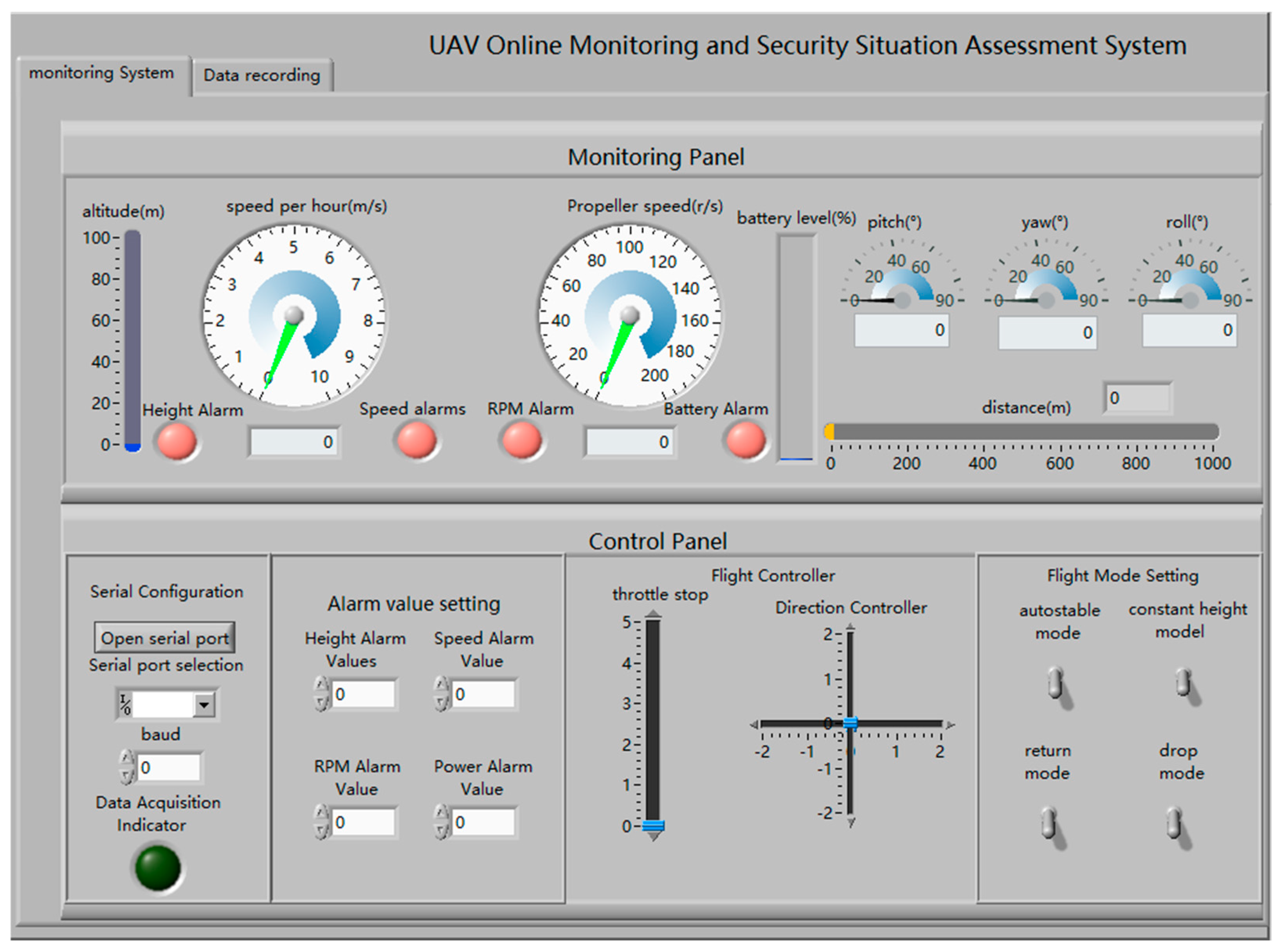
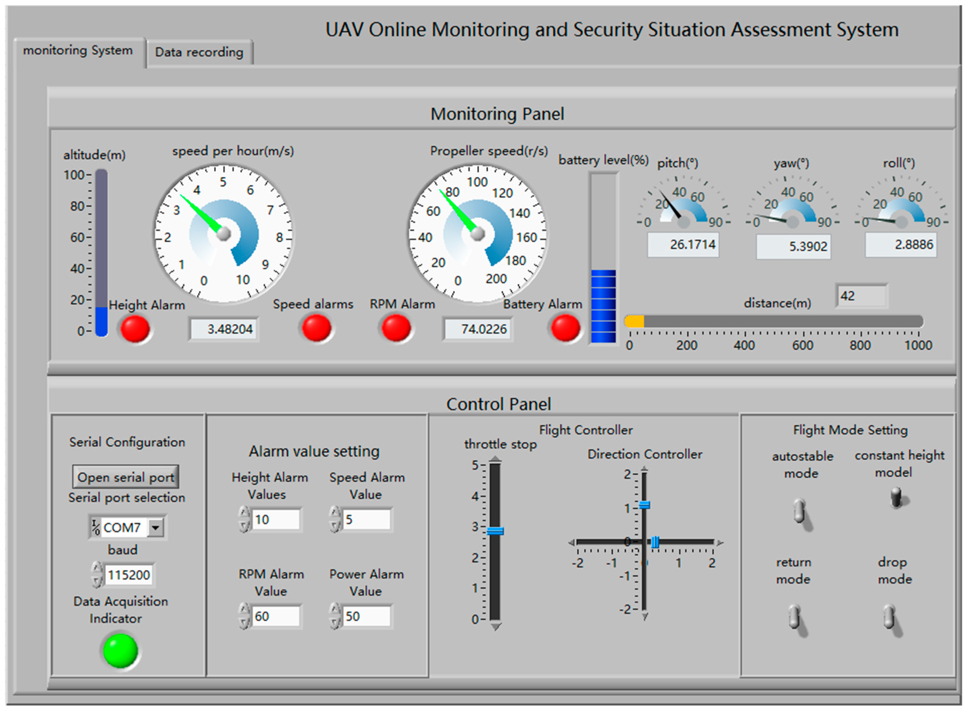
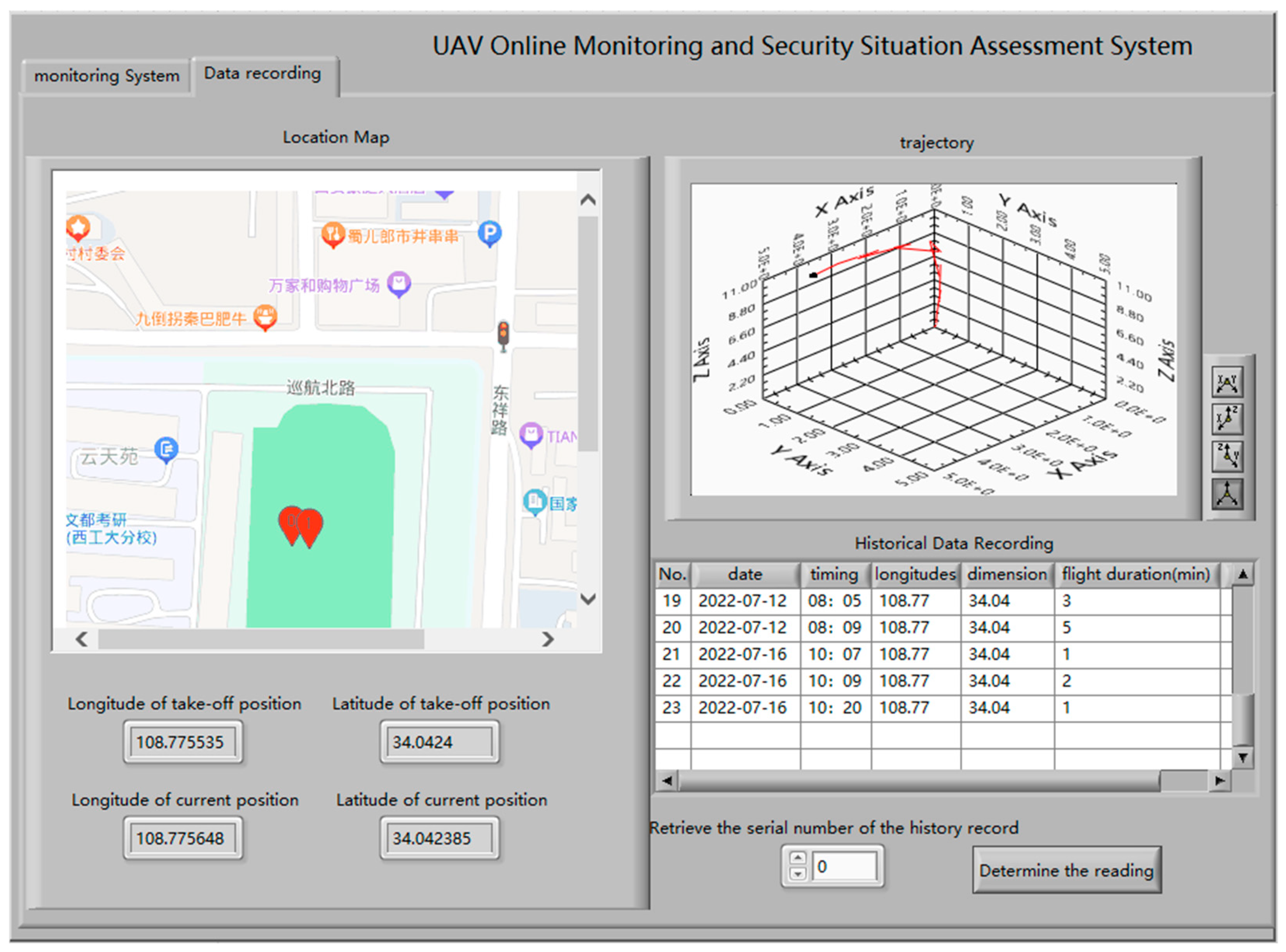
The front panel of the quadcopter UAV flight online monitoring system is shown in Figure 4. There are two tabs set up, the online monitoring system tab and the flight data logging tab. The online monitoring system tab consists of a detection panel and a control panel as shown in Figure 4a. The flight data logging tab consists of real-time position, motion trajectory, and historical data logging as shown in Figure 4b.

3.3.1. Online Monitoring System Tab

The online monitoring system tabbed panel is divided into a detection panel and a control panel. The detection panel display module shows the UAV’s flight altitude, hourly speed, propeller speed, power level, attitude (pitch, yaw, and roll angle), and flight distance. The control panel consists of a serial port configuration module, an alarm threshold setting module, a flight controller module, and a flight mode setting module.
(1) 
Serial port settings
The serial port is the channel for the upper computer to connect with the wireless data transmission module to achieve data transmission with the lower computer. The “Open Serial Port” button controls whether the serial port receives data or not. “Serial Port Selection” selects the COM port for communication with the digital transmission module, and the system selects COM7 for data transmission. The “Baud Rate” option selects the data transmission rate, and the system selects 115,200 for data transmission. The “Data Acquisition” indicator detects whether to receive data. Data are received when the indicator light is green, indicating that the serial module is working properly and receiving data.
(2) 
Flight level indicator
A numerical control displays in real time the altitude at which the body of the UAV is located during flight. The UAV flight altitude measurement system detects the atmospheric pressure and converts it to the corresponding altitude. An altitude threshold is set in the alarm value setting module on the rear panel, and an altitude alarm light is illuminated when the threshold is exceeded.
(3) 
Flight speed display
Calculate the flight hourly speed based on the rate of change of the UAV position and display the hourly speed of the UAV during flight. The hourly speed alarm value can be set directly in the alarm value setting module, and when the hourly speed exceeds the set alarm value, the overspeed alarm lamp lights up.
(4) 
Propeller speed display
The propeller rotation speed displays the maximum speed of the four propeller rotations, measured according to the drive signals from the UAV main control system to the motor drive module. The rotational speed threshold is set to 200 r/s, and the rotational speed alarm value can be set directly in the alarm value setting module, and the rotational speed alarm lamp lights up when the rotational speed exceeds the set alarm value.
(5) 
Battery level display
The UAV power level is used to display the remaining power in the UAV power system during flight. The remaining power is measured according to the power supply voltage in the UAV power supply system. The system sets the alarm value in the alarm value setting module, and when the power level is lower than the set alarm value, the power alarm lamp lights up. The default preset UAV power alarm value is 20%.
(6) 
Attitude display
The UAV attitude module is used to display the three Euler angles (pitch, yaw, and roll) of the real-time position of the UAV flight with respect to the starting coordinate system, and the attitude data are calculated based on the detection of the UAV attitude sensor MPU6050 gyroscope module.
(7) 
Flight distance display
The flight distance is used to display the distance between the UAV and the current plane of the PC, which is calculated and measured according to the latitude and longitude returned from the UAV and the latitude and longitude of the PC, which enables the flyer to observe the flight distance of the UAV in real time.
(8) 
Control module
The control module is divided into alarm value setting, flight controller, and flight mode setting. The initial values of the alarm values are all 0, which need to be set manually and can be freely adjusted in size according to the demand during the running of the program. The flight controller consists of the throttle stop and the direction controller. The throttle stop is presented as a slider control, and it can be adjusted by dragging the slider to change the rotational speed of the propeller. The direction controller is presented in the form of a slider bar with a cross. Dragging the slider bar can change the flight direction in four directions: up, down, left, and right. The flight modes are divided into self-stabilizing mode, fixed height mode, return mode, and drop mode. Presented in the form of a switch control, the switch is toggled to select one of the modes and adjust the UAV’s response to throttle and direction to achieve the desired flight mission.

3.3.2. Flight Data Logging Tab

In order to monitor the real-time position and motion trajectory of the UAV and query the historical data, the flight data logging tab panel is designed with a real-time position module, a motion trajectory module and a historical data logging module.
(1) 
Real-time position module
The real-time position module monitors the real-time latitude and longitude of the UAV. Based on the Baidu map software platform, it is designed to display visually and record the latitude and longitude of the take-off position and the latitude and longitude of the current position at the same time.
(2) 
Flight track module
The flight trajectory module draws a 3D curve map in real time with the UAV’s movement data in space, forming a 3D map of the UAV’s flight trajectory.
(3) 
Historical data recording module
The historical data recording module is used to record and display the historical flight data, and the specific data are saved in the form of files in the computer, which can be queried by the historical data recording.

4. Autonomous Security Evaluation System Design

An estimation of the UAV’s own safety posture can be achieved by measuring data from on-board sensors during UAV flight.

4.1. Aviation Airborne Information Solving

For the collected on-board attitude information, the UAV on-board data can be obtained by solving its corresponding 3D Euler angles according to the quaternion method.
For the collected magnetic field strength information, it can be derived from the magnetometer sensor acquisition using analogue-to-digital conversion. It is enabled to detect magnetic field interference in the space where the UAV is located.
UAV sailing altitude: The atmospheric pressure is measured by barometer, then filtered by discrete frequency domain transform DFT, then filtered by designed frequency domain filter, and finally the space altitude where the current UAV is located can be deduced from the pressure altitude formula.
UAV sailing distance: The latitude and longitude of the UAV are measured through the GPS positioning module, then through the discrete frequency domain transform DFT, then through the designed frequency domain filter for filtering, and then by the latitude and longitude coordinate system conversion formula to calculate the two-dimensional coordinates of the UAV, and combined with the UAV altitude information measured by the barometer, can be derived from the UAV’s spatial three-dimensional position, the definition of the drone sailing distance as the three-dimensional position of the UAV spatial two-parameter. position of the two-paradigm number. That is,
d = | | s | | 2 = x 2 + y 2 + z 2
UAV vacuum velocity: The first order difference of the UAV sailing distance derived from the above sensor measurement information is used to obtain the components of the UAV velocity in the three-dimensional coordinate system, defining the UAV vacuum velocity as the second-paradigm number of the UAV’s spatial three-dimensional velocity components. That is,
v x ( i ) = x ( i ) x ( i 1 ) , i ( 2 , n ) v y ( i ) = y ( i ) y ( i 1 ) , i ( 2 , n ) v z ( i ) = z ( i ) z ( i 1 ) , i ( 2 , n ) v = | | v | | 2 = v x 2 + v y 2 + v z 2
UAV navigation bearing force: The second-order difference of the UAV navigation distance deduced from the above sensor measurement information is used to obtain the component of UAV acceleration in the three-dimensional coordinate system, and the UAV navigation bearing force is defined as the product of UAV acceleration and mass. That is:
a = | | a | | 2 = a x 2 + a y 2 + a z 2 F = m × a
UAV Mach number: Mach number is the ratio of the vacuum speed to the speed of sound. The vacuum speed has been calculated in the above steps, taking into account that the speed of sound is only affected by temperature, which has a dependence on altitude.
A = A 0 × 1 L T 0 × H M a = v A
Magnetic field strength of the space where the UAV is located: This is measured by magnetometer sensor, then filtered by discrete frequency domain transform DFT, then filtered by designed frequency domain filter to output the measured magnetic field strength.
UAV angle of attack: This is measured by the MPU6050 attitude sensor for on-board attitude information, then filtered by the discrete frequency domain transform DFT, then filtered by the designed frequency domain filter to output the measured UAV angle of attack.

4.2. Aviation Airborne Information Solving

According to the value range of different atmospheric data information, the logistic function is used to normalize the UAV information to the interval [0, 1]. According to the sailing distance of UAV, vacuum speed of UAV, sailing bearing force of UAV, Mach number of UAV, magnetic field strength of the space where UAV is located, and the interval where the angle of attack of UAV is located, corresponding Logistic functions, are established, and for a set of data x, the mean value and the maximum and minimum value of the data are calculated as shown in Equation (8), respectively.
max x = x ( n ) E x = 1 n · i = 1 n x ( i ) min x = x ( 1 )
In Equation (8), E x is the mathematical expectation of x, x ( i ) is the i-th order statistic of x, max x is the maximum value of x, and minx is the minimum value of x.
Q = 1 1 1 + e ( x E x ) max x min x
The logistic function maps the monitoring information into the interval [0, 1] and normalizes the data.
The UAV flight data were collected as an example to calculate the corresponding indicators, as shown in Table 1 for the intervals of the above six indicators and the corresponding logistic functions designed to normalize them.
Table 1. Intervals and corresponding LOGISTIC functions for each indicator.
Indicator NameIntervalLogistic Function
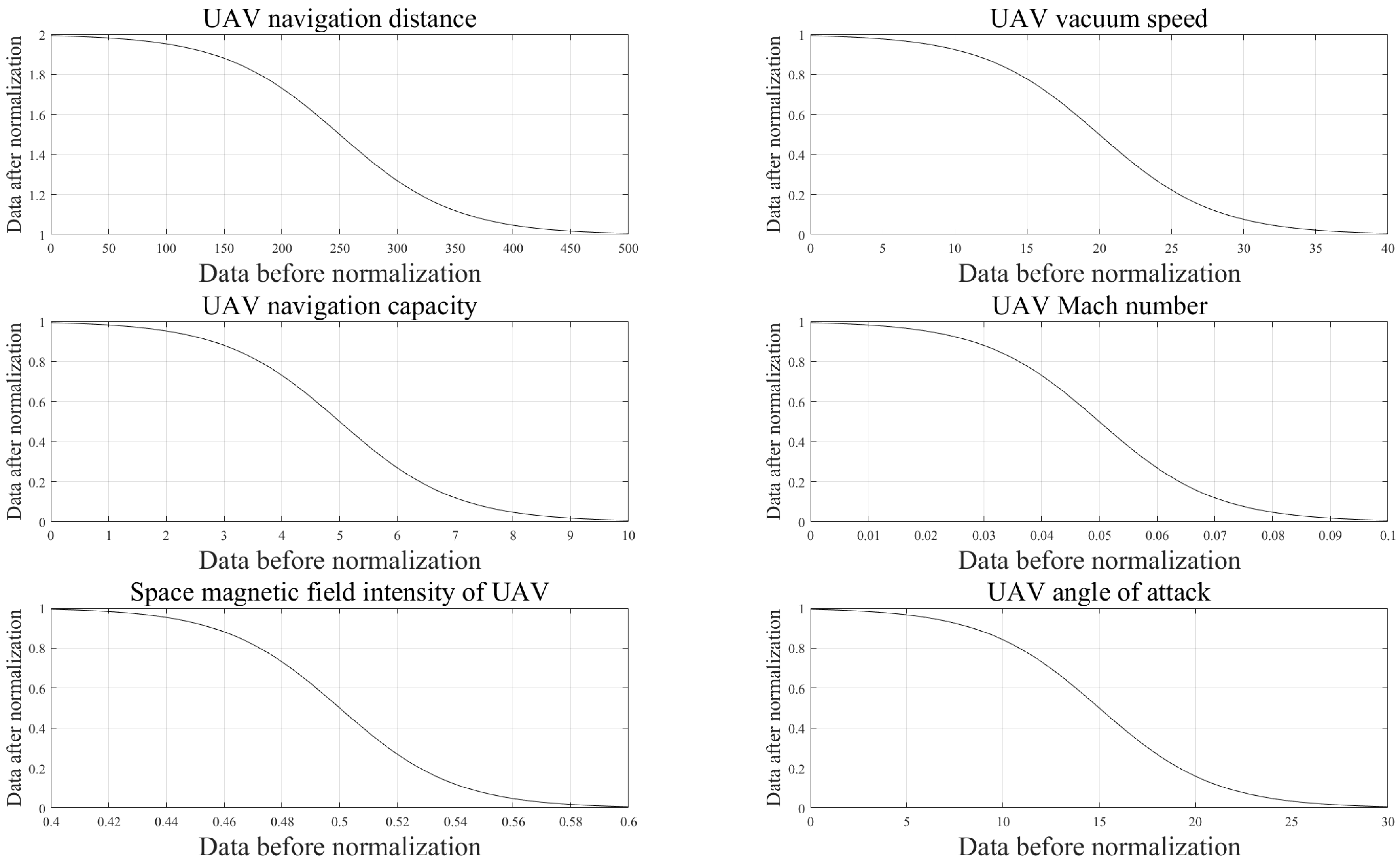
Unmanned aerial vehicle navigation distance[0, 500] x 0 = 1 1 1 + e ( x 250 ) 50 (10)
Unmanned aerial vehicle vacuum speed[0, 40] x 0 = 1 1 1 + e ( x 20 ) 4 (11)
Unmanned aerial vehicle navigation capacity[0, 10] x 0 = 1 1 1 + e ( x 5 ) (12)
Mach Number of unmanned aerial vehicles[0, 0.1] x 0 = 1 1 1 + e 100 · ( x 0.05 ) (13)
Space magnetic field strength of the unmanned aerial vehicle[0.4, 0.6] x 0 = 1 1 1 + e 50 · ( x 0.5 ) (14)
UAV attack angle[0, 30] x 0 = 1 1 1 + e ( x 15 ) 3 (15)
The logistic function normalizing the six indicators is shown in Figure 5.

4.3. Establishment of a Drone Safety Evaluation System

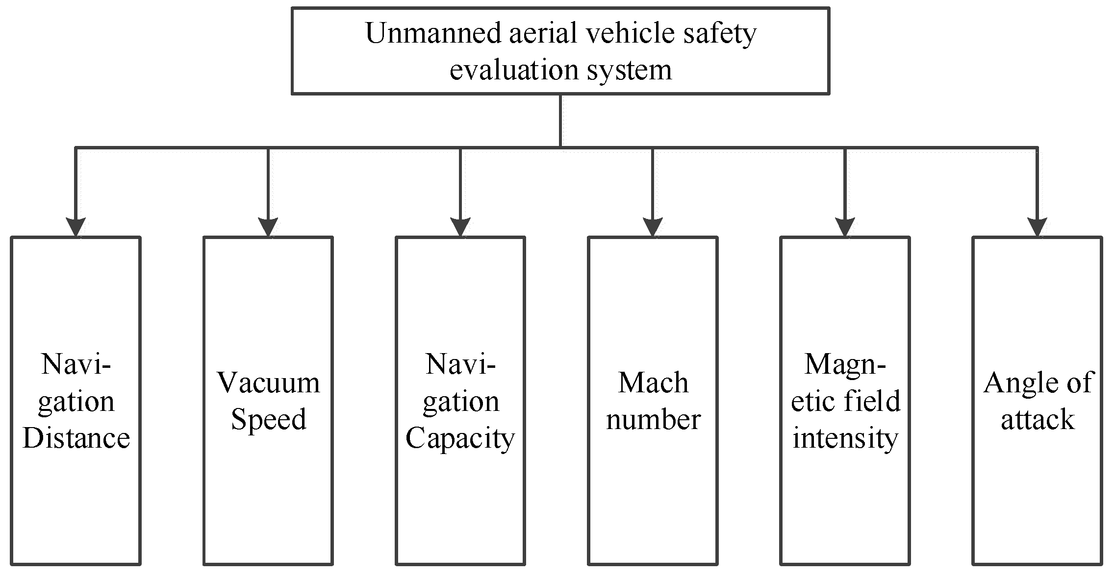
The UAV autonomous safety system is evaluated by six safety evaluation indexes: UAV travelling distance, vacuum speed, travelling bearing force, Mach number, magnetic field strength in space, and angle of attack. The UAV autonomous safety evaluation structure system is shown in Figure 6.
As shown in Figure 6, the evaluation of evaluating maneuver skills is divided into six safety evaluation levels, namely, UAV navigation distance, vacuum speed, navigation bearing force, Mach number, magnetic field strength in space, and angle of attack, and the contribution of the six evaluation levels to the evaluation score can be expressed as shown in Equation (16).
Q = i = 1 6 K i · Q i
The hierarchical analysis method based on stratification determines the weights between the different evaluation levels and constructs a pairwise comparison matrix as shown in Equation (17).
A = 1 1 5 1 5 1 3 1 7 5 1 1 5 7 1 3 5 1 1 5 7 1 3 1 1 5 1 5 1 3 1 7 1 3 1 7 1 7 1 3 1 1 9 7 3 3 7 9 1
Based on the hierarchical analysis method using the pairwise comparison matrix shown in Equation (14), the relative weights between the five evaluation levels were calculated as
[0.055, 0.212, 0.212, 0.55, 0.028, 0.439],
The contribution of the five evaluation tiers to the evaluation score can be expressed as shown in Equation (18).
Q = 0.055 Q 1 + 0.212 Q 2 + 0.212 Q 3 + 0.55 Q 4 + 0.028 Q 5 + 0.0439 Q 6

5. Results and Analysis

After completing the construction of the hardware circuit and debugging the procedures of each module, open the software interface of the upper computer and connect the upper computer with the lower computer for wireless digital transmission. Select the created COM7 port, connect the corresponding port to the upper computer panel, and the serial port will show the connected port, completing the wireless connection. Set the baud rate to 115,200, set the upper and lower parameter thresholds, and press the “Open Serial Port” button to test the system.

5.1. Lower Computer Testing

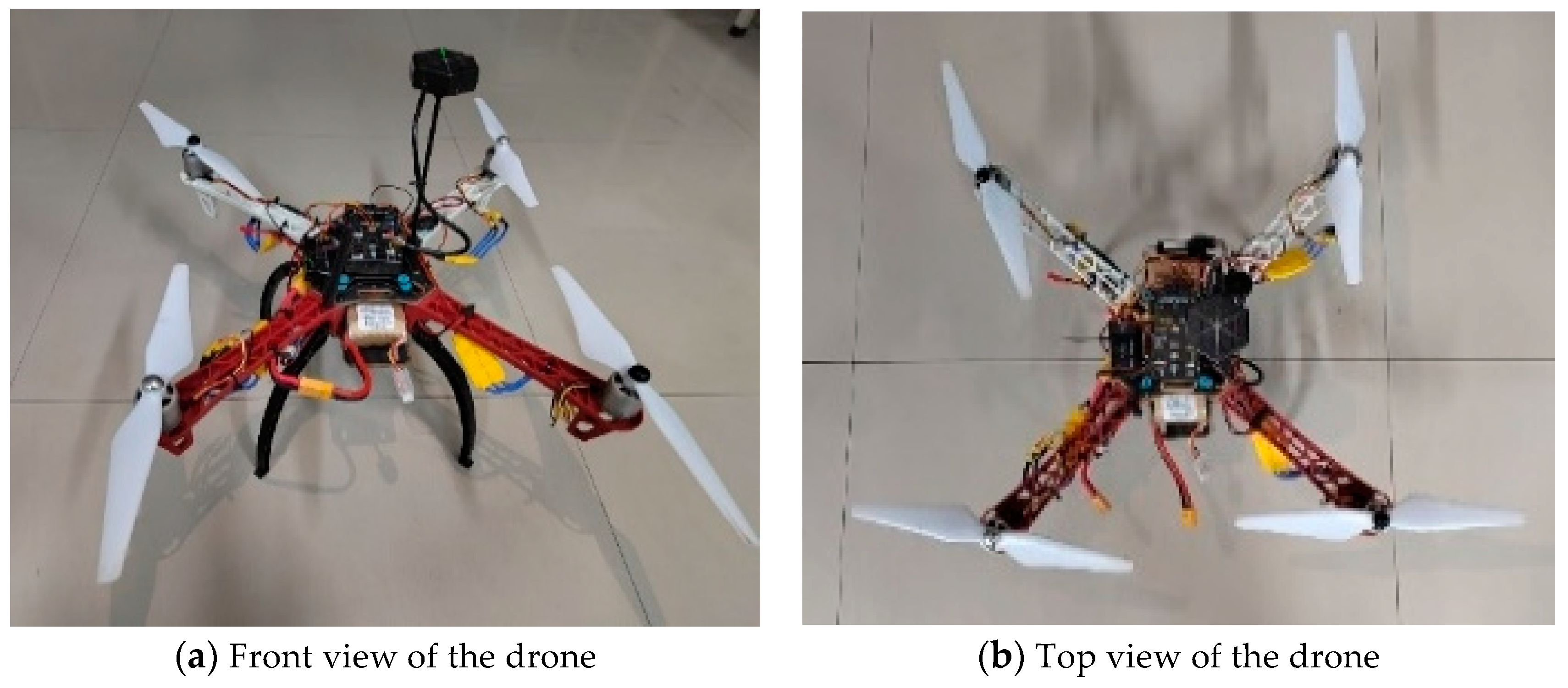
The physical diagram of the quadcopter UAV hardware is shown in Figure 7.
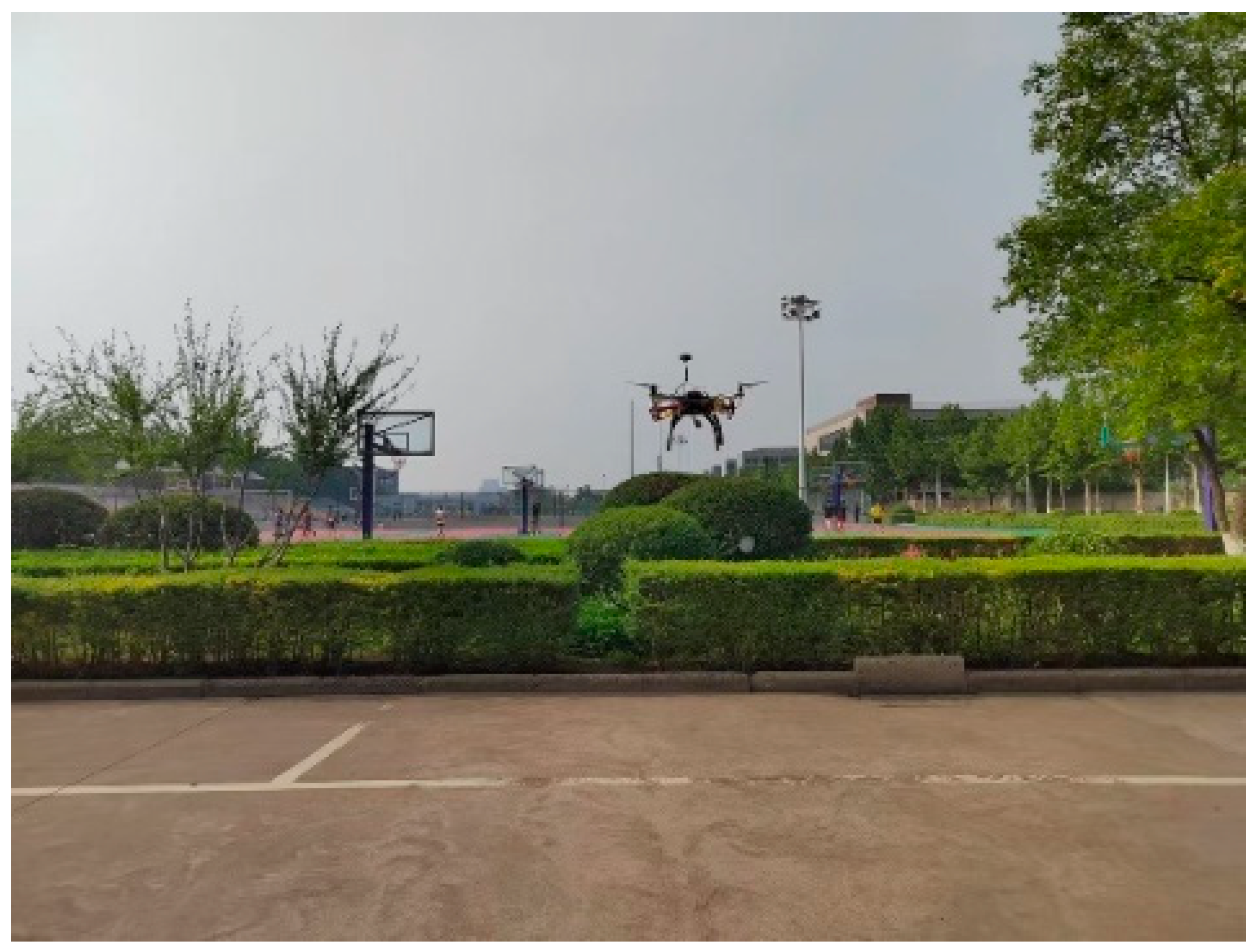
In order to test the flight condition of the lower UAV, an open space was selected for physical flight testing. In this process, assemble the quadcopter drone, access the microcontroller, sensors, and burn programs. Power-up the brushless motor and microcontroller, and when the motor begins to run, manipulate the drone remote control, and the drone will begin to lift off. At this time, the rotational speed signal, hourly speed signal, altitude signal, position information, and other sensor output signals are obtained to generate data. The quadcopter UAV flight test is shown in Figure 8.

5.2. Upper Computer Testing

5.2.1. Flight Test

Run the LabVIEW software, execute the current VI, select the Monitor Panel tab, set the serial port to COM7, set the baud rate to 115,200, and open the serial port. Set the height alarm value to 100 m, the speed alarm value to 5 m/s, the propeller speed alarm value to 150 r/s, the power alarm value to 20, and the UAV flight mode to the self-stabilizing mode. Adjust the UAV throttle gear and direction to make the UAV take off along the nose direction. At this time, the test results of the upper monitoring system front panel are shown in Figure 9.
As shown in Figure 9, after setting the flight mode and adjusting the throttle and direction, the UAV responded to the control signal. The current speed of the UAV was 2.72809 m/s, the rotational speed of the propeller was 65.4954 r/s, the distance flown was 17 m, the flight pitch angle was 21.0385°, the yaw angle was 1.91134°, and the traverse roll angle was 3.14159°. The flight altitude and the battery level were visualized by the thermometer control and the liquid tank control, respectively. The test results show that the quadcopter UAV flight online monitoring system can achieve real-time online monitoring of UAV flight data.

5.2.2. Abnormal Alarm Test

The results of the UAV alarm test are shown in Figure 10.
To test the abnormal alarm function of the UAV, the throttle and direction offset of the UAV were increased in the fixed-height mode. The UAV speed alarm threshold was adjusted to 3 m/s, the altitude alarm threshold was adjusted to 10 m, the propeller rotational speed alarm threshold was adjusted to 60 r/s, and the power alarm threshold was adjusted to 50%. When the UAV exceeded the threshold alarms, the altitude alarm light, the hourly speed alarm light, the rotational speed alarm light, and the power alarm light would light up simultaneously.

5.2.3. Flight Data Recording Test

The flight data logging test is shown in Figure 11.
The drone takes off and flies along the nose direction. The real-time position module, linked to Baidu Maps, displays the take-off and current positions on a 2D map. The take-off position is marked as “0” with a red droplet, and the current position as “1”. The take-off coordinates are 108.775536 longitude and 34.0402 latitude; the current coordinates are 108.775648 longitude and 34.042385 latitude. The motion trajectory module plots the real-time 3D curve of the flight trajectory in the 3D coordinate system. The historical data recording module records test date, time, end flight position coordinates, and flight duration in a tabular format. As shown in Figure 11, there are 23 flight history records. To view specific movement data, enter the serial number in the “Select Read History Record Serial Number” box and click “OK Read” to access the UAV’s historical data at that time.
The historical data of this flight were retrieved, and a segment of the data was intercepted and counted at a 1/5 sampling rate as shown in Table 2.
Using MATLAB to draw this motion trajectory curve, intercept one section of data to draw the data curve of the section, as shown in Figure 12. It can be seen that the drawn curve matches the LabVIEW front panel motion trajectory curve, which verifies the accuracy of the system in monitoring the motion trajectory.

5.3. Security Score Test

Three segments of UAV flight information are collected during UAV navigation and scored using the proposed safety evaluation system, and the flight information and scores are shown in Table 3.
As shown in Table 3, it can be seen that the established safety posture assessment model can be more scientific to assess the safety posture of UAVs, and can assess the safety of UAVs in the UAV flight online monitoring and safety posture assessment system.

6. Conclusions

The UAV flight online monitoring and safety situation evaluation system designed in this paper is capable of collecting and remotely transmitting the UAV’s own information, as well as perceiving and estimating its own attitude. The lower unit of the system employs a barometric pressure sensor to collect barometric pressure data, a GPS position sensor to collect position information, an MPU6050 attitude sensor to collect attitude information of the UAV, and an STM32F427 microcontroller to process the data. The transmission system utilizes a 3DR wireless digital transmission module for data transmission based on wireless digital technology. The upper unit of the system uses LabVIEW to develop the quadcopter UAV flight online monitoring system, which includes functions for display, alarm, control, and data logging; these functions are realized through a dashboard, Boolean lamp, slider, and three-dimensional stereogram, respectively. The display ranges are as follows: altitude from 0 to 100 m, hourly speed from 0 to 10 m/s, rotational speed from 0 to 200 r/s, and power level from 0 to 100%. The control module allows for free adjustment of the upper and lower thresholds of the parameter values according to the actual situation. The analytic hierarchy process is employed to estimate the safety situation of the six navigation parameters, and the safety situation estimation system is established by determining the weight of these parameters. A safety situation estimation can be performed on the real-time state of the UAV during its flight. After testing, the system meets the requirements of a UAV online monitoring system, addresses the issue of insufficient UAV flight detection and carries out a safety situation estimation, and facilitates visual management and safety detection of the UAV’s flight status and operating parameters.

Author Contributions

Literature view, M.Z., L.J. and Y.W.; writing, Z.S., J.Z. and G.S.; editing., J.Z. and G.S. All authors have read and agreed to the published version of the manuscript.

Funding

This work was supported by the 2024 Northwestern Polytechnical University Graduate Student Innovation Fund Project (Program No. 06080-24GH01020101), the Natural Science Basic Research Program of Shaanxi (Program No. 2022JQ-593), and Key R&D Program of Shaanxi Provincial Department of Science and Technology (Program No. 2022GY-089).

Data Availability Statement

The original contributions presented in the study are included in the article, further inquiries can be directed to the corresponding author/s.

Conflicts of Interest

The authors declare no conflicts of interest.

References

  1. Yan, X.; Fu, T.; Lin, H.; Xuan, F.; Huang, Y.; Cao, Y.; Hu, H.; Liu, P. UAV Detection and Tracking in Urban Environments Using Passive Sensors: A Survey. Appl. Sci. 2023, 13, 11320. [Google Scholar] [CrossRef]
  2. Sarkar, N.I.; Gul, S. Artificial Intelligence-Based Autonomous UAV Networks: A Survey. Drones 2023, 7, 322. [Google Scholar] [CrossRef]
  3. Messaoudi, K.; Oubbati, O.S.; Rachedi, A.; Lakas, A.; Bendouma, T.; Chaib, N. A Survey of UAV-Based Data Collection: Challenges, Solutions and Future Perspectives. J. Netw. Comput. Appl. 2023, 216, 103670. [Google Scholar] [CrossRef]
  4. Guan, S.; Zhu, Z.; Wang, G. A Review on UAV-Based Remote Sensing Technologies for Construction and Civil Applications. Drones 2022, 6, 117. [Google Scholar] [CrossRef]
  5. Zhang, J.; Shi, Z.; Zhang, A.; Yang, Q.; Shi, G.; Wu, Y. UAV Trajectory Prediction Based on Flight State Recognition. IEEE Trans. Aerosp. Electron. Syst. 2023, 60, 2629–2641. [Google Scholar] [CrossRef]
  6. Jiandong, Z.; Qiming, Y.; Guoqing, S.; Yi, L.; Yong, W. UAV Cooperative Air Combat Maneuver Decision Based on Multi-Agent Reinforcement Learning. J. Syst. Eng. Electron. 2021, 32, 1421–1438. [Google Scholar] [CrossRef]
  7. Liu, C.; Sun, S.; Tao, C.; Shou, Y.; Xu, B. Sliding Mode Control of Multi-Agent System with Application to UAV Air Combat. Comput. Electr. Eng. 2021, 96, 107491. [Google Scholar] [CrossRef]
  8. Jiang, F.; Xu, M.; Li, Y.; Cui, H.; Wang, R. Short-Range Air Combat Maneuver Decision of UAV Swarm Based on Multi-Agent Transformer Introducing Virtual Objects. Eng. Appl. Artif. Intell. 2023, 123, 106358. [Google Scholar] [CrossRef]
  9. Li, S.; Wang, Y.; Zhou, Y.; Jia, Y.; Shi, H.; Yang, F.; Zhang, C. Multi-UAV Cooperative Air Combat Decision-Making Based on Multi-Agent Double-Soft Actor-Critic. Aerospace 2023, 10, 574. [Google Scholar] [CrossRef]
  10. Khelifi, M.; Butun, I. Swarm Unmanned Aerial Vehicles (SUAVs): A Comprehensive Analysis of Localization, Recent Aspects, and Future Trends. J. Sens. 2022, 2022, 8600674. [Google Scholar] [CrossRef]
  11. Adoni, W.; Lorenz, S.; Fareedh, J.; Gloaguen, R.; Bussmann, M. Investigation of Autonomous Multi-UAV Systems for Target Detection in Distributed Environment: Current Developments and Open Challenges. Drones 2023, 7, 263. [Google Scholar] [CrossRef]
  12. Amodu, O.A.; Bukar, U.A.; Raja Mahmood, R.A.; Jarray, C.; Othman, M. Age of Information Minimization in UAV-Aided Data Collection for WSN and IoT Applications: A Systematic Review. J. Netw. Comput. Appl. 2023, 216, 103652. [Google Scholar] [CrossRef]
  13. Kamkuimo, S.; Magalhaes, F.; Zrelli, R.; Misson, H.; Attia, M.; Nicolescu, G. Decomposition and Modeling of the Situational Awareness of Unmanned Aerial Vehicles for Advanced Air Mobility. Drones 2023, 7, 501. [Google Scholar] [CrossRef]
  14. Sziroczak, D.; Rohacs, D.; Rohacs, J. Review of Using Small UAV Based Meteorological Measurements for Road Weather Management. Prog. Aerosp. Sci. 2022, 134, 100859. [Google Scholar] [CrossRef]
  15. Nwaogu, J.M.; Yang, Y.; Chan, A.P.C.; Chi, H. Application of Drones in the Architecture, Engineering, and Construction (AEC) Industry. Autom. Constr. 2023, 150, 104827. [Google Scholar] [CrossRef]
  16. Al-Dosari, K.; Hunaiti, Z.; Balachandran, W. A Review of Civilian Drones Systems, Applications, Benefits, Safety, and Security Challenges. In The Effect of Information Technology on Business and Marketing Intelligence Systems; Alshurideh, M., Al Kurdi, B.H., Masa’deh, R., Alzoubi, H.M., Salloum, S., Eds.; Studies in Computational Intelligence; Springer International Publishing: Cham, Switzerland, 2023; Volume 1056, pp. 793–812. ISBN 978-3-031-12381-8. [Google Scholar]
  17. Zhang, Y.; Jing, R.; Ji, X.; Hu, N. Application of Wireless Sensor Network Technology Based on Artificial Intelligence in Security Monitoring System. Open Comput. Sci. 2023, 13, 20220280. [Google Scholar] [CrossRef]
  18. Zheng, Z.; Liu, Y. Design of Cloud Storage-Oriented Sports Physical Fitness Monitoring System. Comput. Intell. Neurosci. 2022, 2022, 1889381. [Google Scholar] [CrossRef] [PubMed]
  19. Wu, Z.; Deng, M.; Chen, G.; Liu, Y.; Zhang, Q.; Guo, L. Developing a Geological Disaster Monitoring System Based on Electrical Prospecting. Meas. Sci. Technol. 2023, 34, 045902. [Google Scholar] [CrossRef]
  20. Dai, Y. Endurance Monitoring Method for Rock Climbers Based on Multisensor FDA Model. Math. Probl. Eng. 2022, 2022, 2683399. [Google Scholar] [CrossRef]
  21. Shi, Z.; Shi, G.; Zhang, J.; Wang, D.; Xu, T.; Ji, L.; Wu, Y. Design of UAV Flight State Recognition System for Multi-Sensor Data Fusion. IEEE Sens. J. 2024, 24, 21386–21394. [Google Scholar] [CrossRef]
  22. Yin, F. Practice of Air Environment Quality Monitoring Data Visualization Technology Based on Adaptive Wireless Sensor Networks. Wirel. Commun. Mob. Comput. 2022, 2022, 4160186. [Google Scholar] [CrossRef]
  23. Lu, L. Remote Monitoring System of Digital Agricultural Greenhouse Based on Internet of Things. Scalable Comput. Pr. Exp. 2023, 24, 439–447. [Google Scholar] [CrossRef]
  24. Bo, L.; Liu, Y.; Zhang, Z.; Zhu, D.; Wang, Y. Research on an Online Monitoring System for Efficient and Accurate Monitoring of Mine Water. IEEE Access 2022, 10, 18743–18756. [Google Scholar] [CrossRef]
  25. Shi, Z.; Jia, Y.; Shi, G.; Zhang, K.; Ji, L.; Wang, D.; Wu, Y. Design of Motor Skill Recognition and Hierarchical Evaluation System for Table Tennis Players. IEEE Sens. J. 2024, 24, 5303–5315. [Google Scholar] [CrossRef]
  26. Lim, Y.Z.; Xin, X.; Khoo, T.P. Enhancing UAV Flight Safety through Sensor-Based Runtime Risk Assessment. In Proceedings of the 2022 IEEE 8th World Forum on Internet of Things (WF-IoT), Yokohama, Japan, 26 October–11 November 2022; IEEE: Yokohama, Japan, 2022; pp. 1–5. [Google Scholar]
  27. Shi, Z.; Zhang, J.; Shi, G.; Ji, L.; Wang, D.; Wu, Y. Design of a UAV Trajectory Prediction System Based on Multi-Flight Modes. Drones 2024, 8, 255. [Google Scholar] [CrossRef]
Figure 1. The block diagram of monitoring system structure.
Drones 08 00308 g001
Figure 2. Lower computer software function block diagram.
Drones 08 00308 g002
Figure 3. Flow chart of the front board subprogram.
Drones 08 00308 g003
Figure 4. Front panel of the UAV monitoring system.
Drones 08 00308 g004
Figure 5. Logistic image normalized by different indicators.
Drones 08 00308 g005
Figure 6. Structure of autonomous drone safety evaluation.
Drones 08 00308 g006
Figure 7. Physical figure of quadrotor UAV hardware.
Drones 08 00308 g007
Figure 8. The testing of UAV flight.
Drones 08 00308 g008
Figure 9. The testing of the monitoring system front panel.
Drones 08 00308 g009
Figure 10. UAV alarm testing.
Drones 08 00308 g010
Figure 11. Flight data record testing.
Drones 08 00308 g011
Figure 12. Movement trajectory curve.
Drones 08 00308 g012
Table 2. Cut-off data sampling point statistics.
No.x Coordinates/my Coordinates/mz Coordinates/m
10.0989927900.2841975236.447164730
20.0976292080.2885615536.595019636
30.0962672880.2929320316.743196043
40.0952650600.2971488986.891325279
50.0949805580.3010520947.039038672
60.0957718130.3044815627.185967548
70.0979968580.3072772417.331743236
80.1020137250.3092790747.475997062
90.1081804460.3103270017.618360353
100.1168550540.3102609637.758464437
110.1283781780.3089429547.895906277
120.1429107930.3064626328.029928085
130.0989927900.2841975236.447164730
140.0976292080.2885615536.595019636
Table 3. Security scoring charts.
Name of FactorNormalized Factor StrengthsNormalized Factor StrengthsNormalized Factor Strengths
Navigation distance0.7310.1190.881
Vacuum speed0.5240.2690.354
Navigation capacity0.6900.3100.646
Mach number0.5790.2690.413
Magnetic field intensity0.2690.6220.378
Angle of attack0.57280.3700.256
Weighted scores0.4120.6760.594
Disclaimer/Publisher’s Note: The statements, opinions and data contained in all publications are solely those of the individual author(s) and contributor(s) and not of MDPI and/or the editor(s). MDPI and/or the editor(s) disclaim responsibility for any injury to people or property resulting from any ideas, methods, instructions or products referred to in the content.