Article

Multi-UAV Formation Path Planning Based on Compensation Look-Ahead Algorithm

1
School of Aerospace Science and Technology, Xidian University, Xi’an 710071, China
2
Qian Xuesen Laboratory of Space Technology, China Academy of Space Technology, Beijing 100094, China
3
365th Research Institute, Northwestern Polytechnical University, Xi’an 710072, China
*
Author to whom correspondence should be addressed.
Drones 2024, 8(6), 251; https://doi.org/10.3390/drones8060251
Submission received: 25 April 2024 / Revised: 28 May 2024 / Accepted: 5 June 2024 / Published: 7 June 2024
(This article belongs to the Special Issue Distributed Control, Optimization, and Game of UAV Swarm Systems)

Abstract

:
This study primarily studies the shortest-path planning problem for unmanned aerial vehicle (UAV) formations under uncertain target sequences. In order to enhance the efficiency of collaborative search in drone clusters, a compensation look-ahead algorithm based on optimizing the four-point heading angles is proposed. Building upon the receding-horizon algorithm, this method introduces the heading angles of adjacent points to approximately compensate and decouple the triangular equations of the optimal trajectory, and a general formula for calculating the heading angles is proposed. The simulation data indicate that the model using the compensatory look forward algorithm exhibits a maximum improvement of 12.9% compared to other algorithms. Furthermore, to solve the computational complexity and sample size requirements for optimal solutions in the Dubins multiple traveling salesman model, a path-planning model for multiple UAV formations is introduced based on the Euclidean traveling salesman problem (ETSP) pre-allocation. By pre-allocating sub-goals, the model reduces the computational scale of individual samples while maintaining a constant sample size. The simulation results show an 8.4% and 17.5% improvement in sparse regions for the proposed Euclidean Dubins traveling salesman problem (EDTSP) model for takeoff from different points.

1. Introduction

Unmanned aerial vehicles are extensively used in collaborative reconnaissance, joint strike operations, aerial displays, express logistics, and agricultural spraying, among other domains. This has consequently elevated the control systems for multi-UAV (unmanned aerial vehicle) clusters, denoted as unmanned aerial systems (UAS), to the focal point of current international and domestic research [1,2]. Within the field of UAV research, path planning assumes a position of paramount importance. A recurrent inquiry pertains to the determination of target sequences and the acquisition of the most expeditious flight path or time [3]. This problem bears resemblance to the variant of the traveling salesman problem (TSP) known as the multiple traveling salesman problem (MTSP), which is conventionally studied but harbors certain distinctions [4]. In the research of MTSP, the paths between target points adhere to a geometrically straight distribution, whereas the motion of UAVs adheres to curved trajectories constrained by maximum curvature [5]. This is particularly pronounced in the case of fixed-wing UAVs, where trajectory curvature is bounded, demanding a curvature configuration in the model that aligns more closely with practical requirements [6,7]. Consequently, researchers frequently substitute the path planning for UAVs with Dubins curves [8]. Despite the approximate similarity between UAV path planning and MTSP, the former poses a more formidable challenge due to kinematic conditions such as curvature constraints, necessitating the formulation of novel solution methodologies by researchers [9].
We combined the Dubins problem with the multiple traveling salesman problem (MTSP), coining it the Dubins traveling salesman problem (DTSP). Solving the DTSP entails not only determining the target sequence but also considering that distinct heading angles yield divergent path-planning outcomes. Consequently, the determination of heading angles must precede the establishment of the target sequence [10]. Using a greedy algorithm for the brute-force solution of the DTSP is imprudent, as the computational burden exponentially escalates with the augmentation of target points [11]. Therefore, resolving a pre-defined target sequence remains a common strategy for addressing curvature-constrained path planning. Ma et al. (2007) proffered a receding-horizon algorithm grounded in the retrograde principle, computing a smooth trajectory through the sequence of path points; however, the authors have not yet developed a complete general formula that can characterize the three path points and initial directions of all possible geometric configurations, so as to uniquely determine the optimal trajectory for any problem [12]. Pantelis Isaiah et al. (2015) synergized k-step anticipation with the retrograde principle and disrupted the target sequence by introducing a k-step foresight algorithm; however, this algorithm is only applicable to situations where there are fewer target points [13]. Meanwhile, Izack Cohen et al. (2017) introduced a novel class of discretized look-ahead algorithms (DLAAs), discretizing the heading orientation angles (HOAs) at various waypoints and formulating an integer optimization problem. The resolution is then ascertained using an integer programming solution, but this algorithm suffers from high computational complexity and low computational efficiency in large-scale formation calculations [14].
This article mainly studies the problem of path planning for fixed-wing unmanned aerial vehicle formation. Firstly, we propose a heading angle calculation algorithm based on four-point optimization and called the heading angle compensation look-ahead algorithm. Building upon the receding-horizon algorithm, we introduce the influence of the heading angle of any adjacent point, be it antecedent or subsequent, upon the selection of the intermediary point and propose a general formula for calculating the heading angle. This algorithm is compared with other algorithms, such as the 2-opt algorithm [15], the alternating algorithm (AA) [16], and the Euclidean distance traveling salesman problem (ETSP). Secondly, we have adopted a pre-allocation mechanism to address the computational problem of path planning in large-scale drone formations. Within the context of multiple UAV formations, we use the ETSP algorithm for the pre-allocation of target points, thereby creating several subsets of designated points. Subsequently, we apply the compensatory foresight algorithm introduced in the second section to each subset, striking a balance between computational scale and the optimization of pathways.

2. Problem Description and Necessary Theories

The typical scenario of UAV swarm mission path planning depicted in Figure 1 in this paper involves multiple fixed-wing UAVs conducting point-based search and reconnaissance within a designated area ( N u a v N t a r g e t ). Initially, after obtaining coordinates of various target points scattered within the area via satellite reconnaissance or other means, the command center assigns these task points to the leader UAV based on the distribution of the target points. The leader UAV then plans paths for all target points, considering the maneuverability of the UAVs. Subsequently, the planned task paths are distributed to each follower UAV [17]. Following the assigned task paths, multiple UAVs will conduct a search of all target points.
However, constrained by the size of the target area and the maneuverability of fixed-wing UAVs themselves, in practical applications, UAV formations often encounter scenarios where they must fly around dense distributions of target points. This requires UAVs to perform extensive curved maneuvers to reach the target point coordinates, significantly reducing the efficiency of the UAV formation’s search and increasing the search time. Therefore, we recommend determining the sequence of target points and the heading angle for each UAV towards every target point before path planning to optimize the UAV formation’s path planning.
This remains challenging for various reasons. Academically, Dubins curves are commonly used to simulate the shortest paths between target points [18]. However, the inherent uncertainty of Dubins curves results in different paths between target points based on different angles, meaning there are countless possible paths between these points. Therefore, there is a need to design a new algorithm that can provide a general formula for calculating heading angles to determine the optimal heading angle for each target point. Additionally, in large-scale UAV formations, as the number of target points increases, the computational complexity of the model increases exponentially. Therefore, efficient path planning while maintaining manageable computational complexity is also a critical consideration.

2.1. Dubins Path

The trajectory of fixed-wing unmanned aerial vehicles is a linear variation, delineating its trajectory as a curve [19].
X t = x t , y t , θ ( t ) T R 2 × S 1
This paper focuses solely on the motion of unmanned aerial vehicles in a two-dimensional environment, where x and y represent the Cartesian coordinates of the drone’s position, and θ represents the angle of the UAV relative to the X-axis, which is the heading angle of the drone.
Assuming a model where the UAV’s velocity is set at 1 and the maximum curvature is 1/γ, the kinematic equations can be expressed as follows:
x ˙ = c o s θ
y ˙ = s i n θ
θ ˙ = u / γ
In this context, θ 1 / γ 1 / γ , and the constant u is the control variable that varies with time for the drone, with an absolute value of u 1 .
In mathematical modeling, the simulation of an unmanned aerial vehicle’s curved motion with curvature 1/γ is typically achieved through the utilization of Dubins curves [20]. J-D. Boissonnat et al. had a detailed account of the specific derivations for various scenarios involving Dubins curves [21]. Dubins curves are commonly divided into two major families: the CCC family, which includes RLR and LRL, and the CSC family, which includes RSR, LSL, RSL, and LSR [22]. C represents an arc with curvature not exceeding 1/γ, S represents a straight line, L represents a counterclockwise curve, and R represents a clockwise curve. The Dubins curve is depicted by drawing the maximum curvature radius circle tangent to the initial state, followed by the delineation of two tangent lines connecting the circles. Through defined coordinate positions and heading angles, the shortest path can be determined [23].
The Dubins shortest-path problem belongs to the realm of solving minimization problems in traditional optimal control theory. In this problem, the initial and final states of the UAV are uncertain, and the control vector is a continuous function, making it amenable to solution using variational methods. In the UAV motion model presented in this paper, the UAV’s velocity is set to 1. The performance functional for the shortest path of Dubins curves can be represented by an integral, as shown in Equation (5).
m i n J = t 0 t f L ( x , y , θ ) d t = t 0 t f 1 d t
In Equation (5), t 0 and t f represent the initial and terminal times of the UAV. We set φ x , φ y , φ θ as parameters for the shortest path. Combining Equations (2)–(4), which represent the UAV’s kinematic equations, with Equation (5), which represents the performance functional, we construct the Hamiltonian function based on the theorems of optimal control theory. Therefore, the Hamiltonian function for the UAV’s shortest path is given as
H x , y , θ = 1 + φ x c o s θ + φ y s i n θ + φ θ u / γ
According to the Pontryagin maximum principle, we can obtain the necessary conditions for the shortest path of the Dubins curve [24].
d d t φ x φ y φ θ = 0 0 φ x s i n θ φ y c o s θ
The above equation indicates that φ x and φ y are piecewise constant within the UAV’s motion cycle [ t 0 , t f ]. Due to the linearity of the Hamiltonian in the control function u, there are two distinct types of optimal control [25]. In the situation that φ θ 0 , u takes on the value of u = s i g n ( φ θ ) . Conversely, when φ θ = 0 , u ∈ [−1, 1]. The former condition corresponds to the maximum curvature arc with a radius of r, while the latter aligns with the trajectory of a straight line where the direction is given by t a n θ = φ x / φ y .
Sussmann and his colleagues, in their seminal paper in 1991, established the existence of a solution to the Dubins path problem, wherein the optimal trajectories manifest as either CαCβCδ or CαSdCβ, where 0 ≤ α, δ < 2π, π < β < 2π, and d ≥ 0 [26]. Given the inherent non-uniqueness of solutions to the Dubins path, generally, multiple trajectories can converge to the minimal value [27]. As discerned from Equation (7), the shortest path of the Dubins curve is intricately linked to the heading angle. The choice of distinct heading angles results in divergent selections within the path details. Consequently, determining the heading angles in the Dubins curve emerges as a pivotal factor in ascertaining the unmanned aerial vehicle’s shortest path [28]. In Section 2.2, we introduce a heading angle model that exhibits a notable enhancement when compared to existing algorithms. The specific data comparisons are presented in Section 4.

2.2. Compensatory Look-Ahead Algorithm

In Section 2.1, the necessary conditions for the shortest path and the existence of the optimal solution are demonstrated. It is also shown that the shortest path of Dubins curves is closely related to the heading angle. Determining the heading angle in Dubins curves is crucial for determining the shortest path for unmanned aerial vehicles. Compared to path planning between two waypoints, smooth curve optimization between three waypoints better meets practical requirements and yields superior planning results. Ma et al. introduced a midpoint x 1 , y 1 between the initial point x 0 , y 0 and the terminal point x 2 , y 2 of the Dubins curve. Referring to the analysis in [26], they obtained the boundary relationships of the midpoint, as shown below.
φ x t 1 + = φ x t 1 + k 1 φ y t 1 + = φ y t 1 + k 2 φ θ t 1 + = φ θ t 1 H t 1 + = H t 1
In Equation (8), k 1 and k 2 are constants. Combined with Equation (7), it becomes evident that φ x and φ y exhibit a discontinuous jump at x 1 , y 1 and are not continuous.
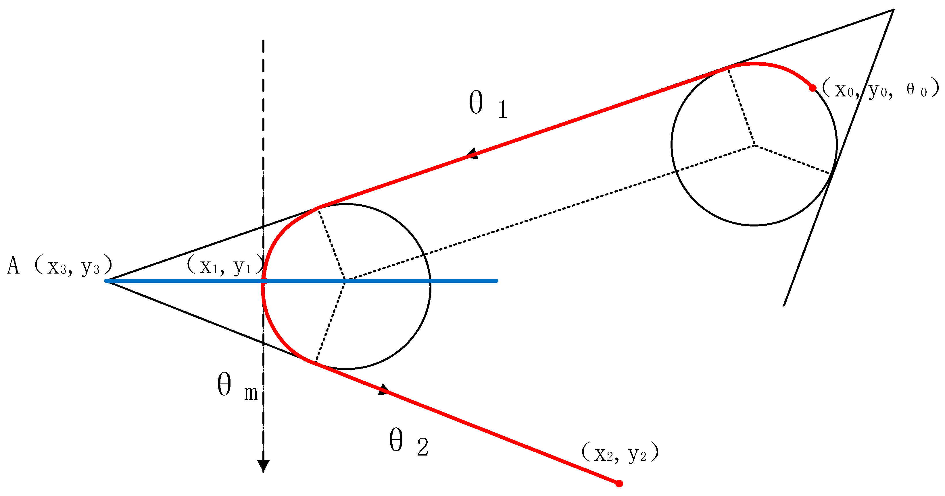
Figure 2 presents a schematic diagram of the optimal path. The red trajectory represents the Dubins optimal path, which passes through the initial point, midpoint, and terminal point. θ 0 is the heading angle (relative to the X-axis) of the initial point x 0 , y 0 . θ 1 and θ 2 are the angles of the line where they are located (relative to the X-axis). θ m represents the heading angle of the midpoint x 1 , y 1 . Ma et al. reached the conclusion that a line drawn from the midpoint x 1 , y 1 to the point of intersection A x 3 , y 3 of the two line segments bisects the angle of intersection, which is shown by the blue line segment in Figure 2. On the optimal path, φ θ = 0 and d φ θ / d t = 0 . Substituting these values into Equation (8) allows the system of simultaneous equations to be solved. The results can then be utilized in Equation (9).
φ x = cos θ 1 φ y = sin θ 1 φ x + k 1 = cos θ 2 φ y + k 2 = sin θ 2
From Equation (9), we can derive that k 1 / k 2 = tan ( θ 1 + θ 2 ) / 2 . The Hamiltonian function is continuous along the optimal trajectory at point ( x 1 , y 1 ). Therefore, it can be represented as follows:
min u 1 1 + φ x cos θ m + φ y sin θ m + φ θ u = min u 1 1 + ( φ x + k 1 ) cos θ m + φ y + k 2 sin θ m + φ θ u
From the above equation, it can be deduced that
k 1 cos θ m + k 2 sin θ m = 0
From Equations (7) and (9), Equation (10) can be obtained.
θ m = θ 1 + θ 2 2
By Equation (10), the midpoint heading angle of the shortest path can be obtained, and the solution to the coupled trigonometric equations can be found. While this can be accomplished numerically, it is challenging to describe using a general formula. In their paper, Ma et al. did not provide a complete equation that could represent all possible geometric configurations of three path points and initial direction, thus uniquely determining the optimal trajectory for any problem. Solving the coupled trigonometric equations can be performed numerically but is difficult to describe with a general formula. Therefore, based on the horizon backtracking principle, we propose a four-point optimization-based algorithm for calculating the heading angle (Algorithm 1) and provide a general formula for computing the heading angle size at the target point.
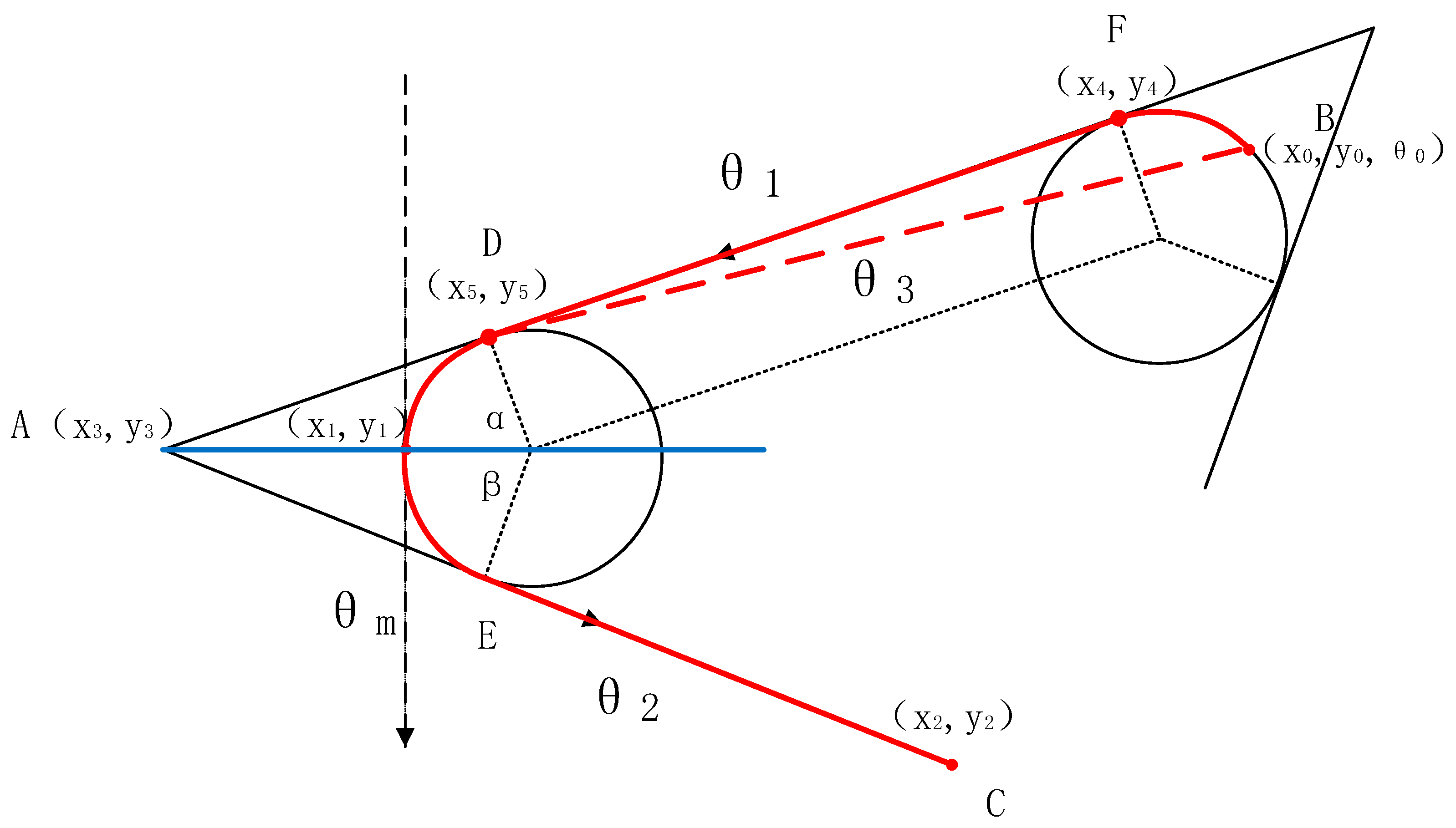
First, let us consider the scenario where the distances between the initial, intermediate, and terminal waypoints are relatively long. Figure 3 illustrates the path planning between the initial, intermediate, and terminal waypoints, where the solid red lines represent Dubins trajectories. Point F ( x 4 , y 4 ) and point D ( x 5 , y 5 ) denote the tangent points of two circular trajectories. While the midpoint heading angle θ m can be solved using Equation (10), when the distances between the initial and intermediate points are considerable, the error between the angle θ 1 (relative to the X-axis) of the line segment connecting point F ( x 4 , y 4 ) and point D ( x 5 , y 5 ) and the angle θ 3 (relative to the X-axis) of the line segment connecting the initial point B ( x 0 , y 0 ) and the tangent point D ( x 5 , y 5 ) (red dashed line segment) can be neglected. Solving for the coordinates of tangent point F ( x 4 , y 4 ) is difficult, so the direction angle θ m (relative to the X-axis) of the intermediate point can be directly solved using the coordinates of the initial point B ( x 0 , y 0 ) substituted into Equation (12).
From Figure 3, the total range L between the three points after task planning can be obtained, as shown below:
L = L B D + L E C + S a r c D E > a + b + α + β 180 π R 2 R sin α 2 2 R sin β 2 > a + b + α + β 180 π R 4 R sin α + β 4 cos α β 4
From Equation (13), it can be seen that the value of L is related to α, β, as shown in Equation (14):
S = α + β 180 π R 4 R sin α + β 4 cos α β 4
It is discernible from the equation that as the sum of α and β decreases, reaching equality (α = β), the value of Equation (14) attains its minimum. Illustrated graphically, when the center O of the circle lies on the angle bisector of angle A, the total course length L achieves its minimum value, denoted as L m i n = a + b + α + β 180 π R 4 R sin α + β 4 . The heading angle θ m at the midpoint x 1 , y 1 is given by θ m = θ 3 + θ 2 2 .
Next, let us consider the scenario where the distances between the initial, intermediate, and terminal waypoints are relatively close. Figure 3 depicts the path planning between the initial, intermediate, and terminal waypoints, where the solid red lines represent Dubins trajectories. However, when the distances between the initial and intermediate points are close, the error between the angle θ 1 (relative to the X-axis) of the line segment connecting point F ( x 4 , y 4 ) and point D ( x 5 , y 5 ) and the angle θ 3 (relative to the X-axis) of the line segment connecting the initial point B ( x 0 , y 0 ) and the tangent point D ( x 5 , y 5 ) (red dashed line segment) cannot be neglected. Therefore, we cannot directly substitute the coordinates of the initial point B ( x 0 , y 0 ) into Equation (12) to solve for the direction angle θ m (relative to the X-axis) of the intermediate point. In this scenario, the heading angles of the initial and terminal points will affect the values of θ 1 and θ 2 .
From Figure 3, it can be observed that when the waypoints are close to each other, the actual θ 3 can significantly differ from the original θ 1 . In such cases, continuing to use θ 1 for calculations would lead to significant errors. It is challenging to obtain a solution for the fully coupled trigonometric equations. To address this issue, we propose a four-point optimization algorithm for calculating the heading angles, aiming to minimize the deviation caused by error terms.
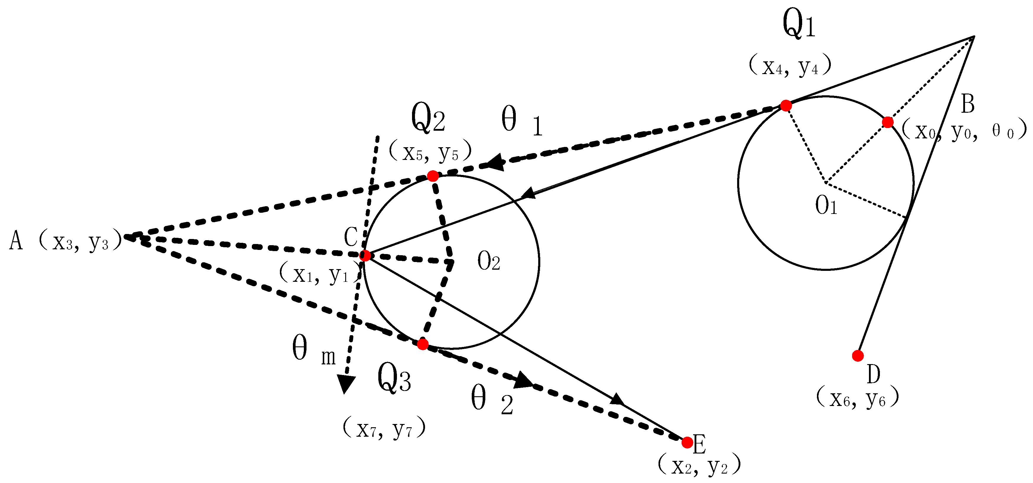
In the scenario where the initial point ( x 0 , y 0 ) is close to the midpoint, the heading angle at the initial point will affect the heading angle at the midpoint. In this paper, we introduce an adjacent point ( x 6 , y 6 ) to the initial point ( x 0 , y 0 ). We preprocess the target point ( x 6 , y 6 ) using the optimization algorithm for the scenario where the initial point is far from the midpoint, as described in Figure 3, to obtain a tangent point Q1 ( x 4 , y 4 ). Then, we use this tangent point Q1 ( x 4 , y 4 ) instead of the initial point ( x 0 , y 0 ) as the new target point. We repeat the previous step for the midpoint ( x 1 , y 1 ). This process allows us to obtain a compensated heading angle θ m for the midpoint. As shown in Figure 4, θ 1 represents the angle of the line segment connecting tangent points Q1 ( x 4 , y 4 ) and Q2 ( x 5 , y 5 ), and θ 2 represents the angle of the line segment connecting tangent point Q3 ( x 7 , y 7 ) and the terminal point C. O1 and O2 are the centers of the two circular trajectories. The solid black line represents the process of solving for the substitute point Q1, and the dashed black line represents the process of using the substitute point Q1 instead of the initial point B to solve for the direction angle θ m of the midpoint.
θ m = θ 1 + θ 2 2
Algorithm 1. Compensation look-ahead algorithm
Input: B x 0 , y 0 , C x 1 , y 1 , D x 6 , y 6 , E x 2 , y 2 , R
Output: compensation heading angle θ m
1:   Center of circle O 1 = B + ( ( B C + B D ) / B C 2 + B D 2 ) / 2
2:   Distance from point to tangent point C Q 1 = C O 1 2 R 2
3:   Acquiring tangent point Q 1 = C O 1 C O 1 C o s S i n a s i n R C Q 1
4:   Center of circle O 2 = c + ( ( C Q 1 + C E ) / C Q 1 2 + C E 2 ) / 2
5:   Distance from point to tangent point B Q 2 = B O 2 2 R 2
6:   Distance from point to tangent point B Q 3 = B O 2 2 R 2
7:   Acquiring tangent point Q 2 = B O 2 B O 2 C o s S i n a s i n R B Q 2
8:   Acquiring tangent point Q 3 = E O 2 E O 2 C o s S i n a s i n R E Q 3
9:   Obtain compensation heading angle θ m = a c o s ( ( x 2 x 7 ) Q 3 E ) + a c o s ( ( x 5 x 6 ) Q 1 Q 2 ) 90 °
10:   end

3. Model Decomposition

3.1. MTSP Model Based on Shortest Distance

The multiple traveling salesman problem (MTSP) is an extension of the traveling salesman problem (TSP) [29,30]. In the MTSP problem, there are n couriers assigned to visit m destinations, where m exceeds n. Each destination is assigned to only one courier, with the objective of minimizing the combined travel distance of all couriers [31]. Task planning of a drone cluster can be seen as an instantiation of the MTSP. It can be succinctly described as follows: provide an undirected graph G = (V, A), where V is the set of nodes, and A is the set of arcs representing road segments. The arcs of the undirected graph G have non-negative costs, and the objective function is to divide V into g non-empty subsets S u b i g 1 and find the minimum cost through each target point in each subset S u b i [32].
The total range from the starting point of the drone cluster to the return of all drones is used as the optimization objective of the MTSP model. There are n task target points, m drones, and the coordinates of all target points are represented by T a r g e t = ( x 1 , y 1 ) , ( x 2 , y 2 ) , , ( x n , y n ) . Therefore, the distance between the two points after the drone cluster task planning can be expressed as
d i , j = x i x j + y i y j
The drones in this paper are all fixed-wing drones, which are different from rotary-wing drones. The trajectory change in fixed-wing drones belongs to a linear process. Therefore, the distance equation between the two points needs to add constraints that meet the trajectory of the drone. Here, we simulate the actual trajectory-change ability of the drone using a Dubins curve with a turning radius of 100 m:
d i , j = l + r + D
In Equation (17), D represents the straight portion of the Dubins curve between adjacent task points in the task planning trajectory, and l and r are the arc lengths between adjacent task points and the straight line, respectively.
The optimization objective of the UAV swarm Dubins multiple traveling salesman model is to minimize the total flight distance of the UAV swarm. According to Equation (17), the objective function can be represented as follows:
min L = i = 1 , j = 1 , q = 1 n , n , m d i , j k i , j , q
In Equation (18), k i , j , q represents whether UAV q has a planned task between target points i and j. The value of k i , j , q is either 0 or 1. The constraint functions are as follows:
i = 1 , j = 1 , q m n , n k i , j , q k
i = 1 , j = 1 , q = 1 n , n , m k i , j , q = n
i n , j n , q = 1 m k i , j , q = 1
d 1 , w = x 1 , y 1 , x w , y w = 0 , ( x , y ) T a r g e t
Equation (19) is the number of targets assigned to each drone, which ensures that each drone is assigned no less than k targets; Equation (20) represents the total number of targets allocated to the drone cluster, which ensures that all target points are allocated; Equation (21) is the number of times the target point is assigned to the drone, and this constraint ensures that each point is only assigned once; and Equation (22) represents the decision criterion for the starting and ending points. x w , y w denotes the coordinates of the last target point planned for a single UAV, indicating that each aircraft must start and end at the same point.
Dijkstra algorithm is a classic method for solving the MTSP (multiple traveling salesman problem), but it is only suitable for scenarios with a small number of samples. The computational complexity increases exponentially with the number of samples, making it unsuitable for large-scale UAV formations in the current context. The discrete DTSP method (DDTSP) is another classical approach for handling the MTSP problem. In DDTSP, for each target, h possible angles are considered, and the interval [0, 2π) is uniformly divided into h sub-intervals. The resulting discrete DTSP (DDTSP) can be transformed into an integer linear programming (ILP) problem. DDTSP method is equivalent to the generalized asymmetric traveling salesman problem with n clusters and 1 + h (n − 1) cities (Noon Bean, 1991), which requires a small value of h. However, the minimum time function of the Dubins model is non-continuous. Therefore, to approximate the optimal solution of DTSP, a larger value of h is required [33]. When the number of task points is small, DDTSP can provide the optimal path, but there are problems of high computational load and slow computational efficiency in large-scale task points and multiple traveling merchants [34,35]. In order to balance the number of task points and computational efficiency, the fourth section proposes a DTSP processing method based on ETSP classification, which simplifies the computational workload while ensuring the shortest path. The specific data comparisons are shown in the fourth section.

3.2. UAV Formation EDTSP Model

In the scenario of multiple unmanned aerial vehicles (UAVs) tasked with multiple objectives, direct application of the DDTSP algorithm for solving the shortest path is deemed imprudent. Hence, a preprocessing step for the sequential arrangement of mission objectives becomes imperative. This paper introduces a preprocessing DTSP model based on the ETSP algorithm called the EDTSP model. The specific approach of this model is outlined as follows.
Let the set of target points be denoted as T a r g e t = ( x 1 , y 1 ) , ( x 2 , y 2 ) , , ( x n , y n ) R 2 , and the ensemble of UAV formations as U. We conceptualize the DTSP problem as an ETSP problem for solving and computing the mission target points, obtaining subsets S u b i = ( x i , y i ) T a r g e t . These obtained subsets of targets serve as the target point set to be solved. We use the compensatory look-ahead algorithm proposed in Section 2 of this paper to determine the heading angle size for each target point, completing the path planning. The planning results of several subsets constitute the overall path planning. Pre-grouping the original task target points with the ETSP algorithm reduces the dimensionality in the DTSP solving process, thereby reducing computational complexity.
Subsequently, within each subset S u b i , we use the compensatory look-ahead algorithm to solve the DTSP problem for the target sequence, thereby deriving UAV formation planning paths that meet the specified requirements. The specific process of the model is shown in Figure 5. To illustrate our model method, let us illustrate our model approach with the following example: Suppose we have a task point set consisting of 3n target points, and we have m UAVs for surveillance, with each UAV assigned to n targets. We use the ETSP algorithm to plan paths for the target set, resulting in three subsets of targets. After allocating the subsets, under the constraints of Dubins curves and UAV performance, where θ belongs to 1 / γ , 1 / γ , we solve the TSP problem to obtain the optimal trajectories. We compute the results for the three subsets and combine them to form the overall planning results. If we were to directly solve the DTSP model using bio-inspired algorithms, we would need to consider ( 3 n ) ! cases. However, by preprocessing the target point set with the ETSP model, we only need to consider 3 n ! cases, greatly reducing the computational complexity.

4. The Analysis of the Simulations

In the third and fourth sections, we introduced a compensatory look-ahead algorithm based on four-point optimization and a path-planning model for multi-UAV formations in multi-tasking scenarios. To prove the accuracy of our algorithm and model, we randomly distributed a certain number of target points in both dense (1000 m × 1000 m) and sparse (5000 m × 5000 m) regions. Using various algorithms, we generated the shortest planned paths.
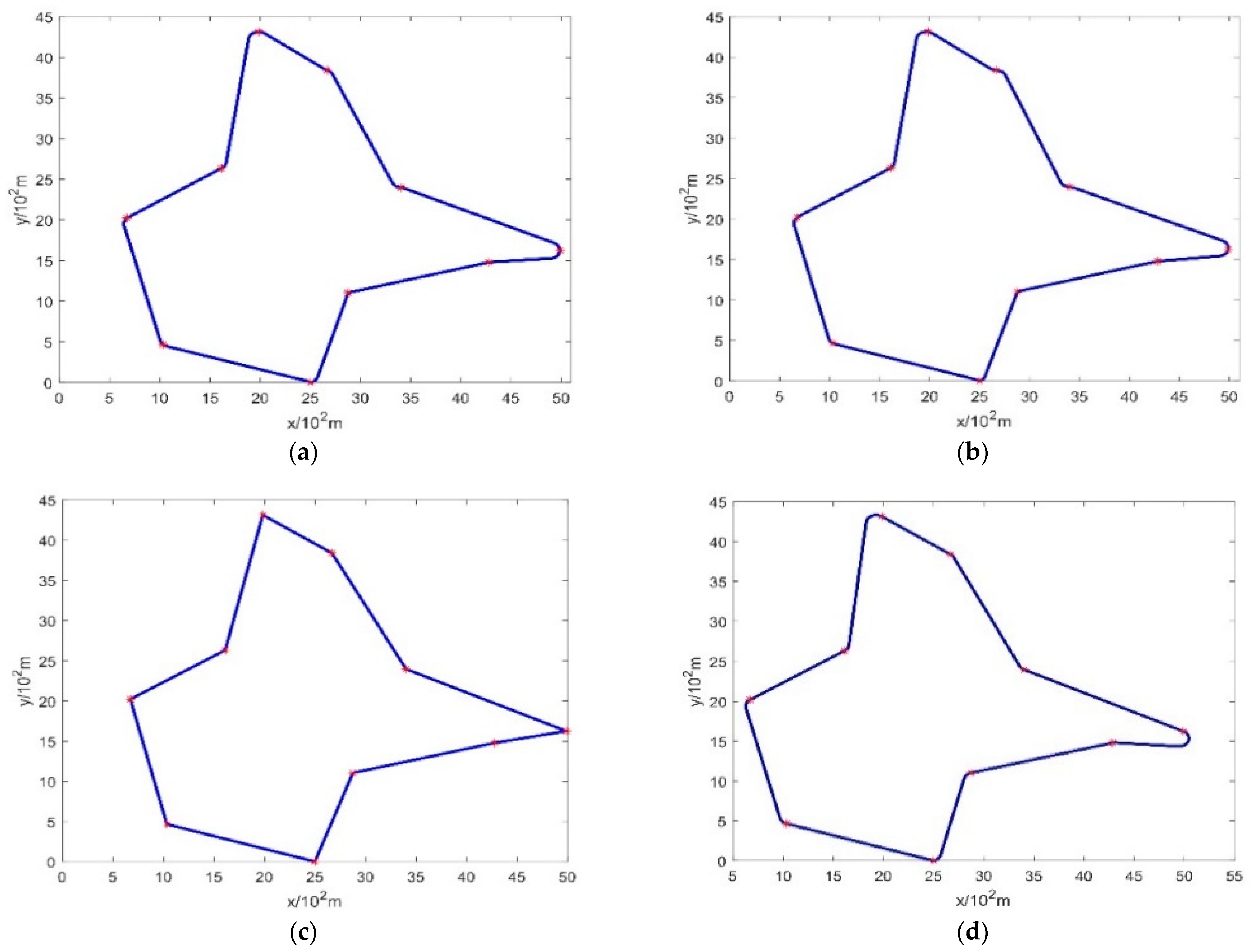
Simulation 1: Using a single UAV, taking off from any location, we executed trajectory planning for ten task points in the dense region. Upon completing the tasks, the UAV returned to the departure point. We compared the itineraries of planning paths utilizing the compensation look-ahead algorithm, 2-opt look-ahead algorithm, alternating algorithm, and the ETSP model. Comparing the search efficiency of the four models.
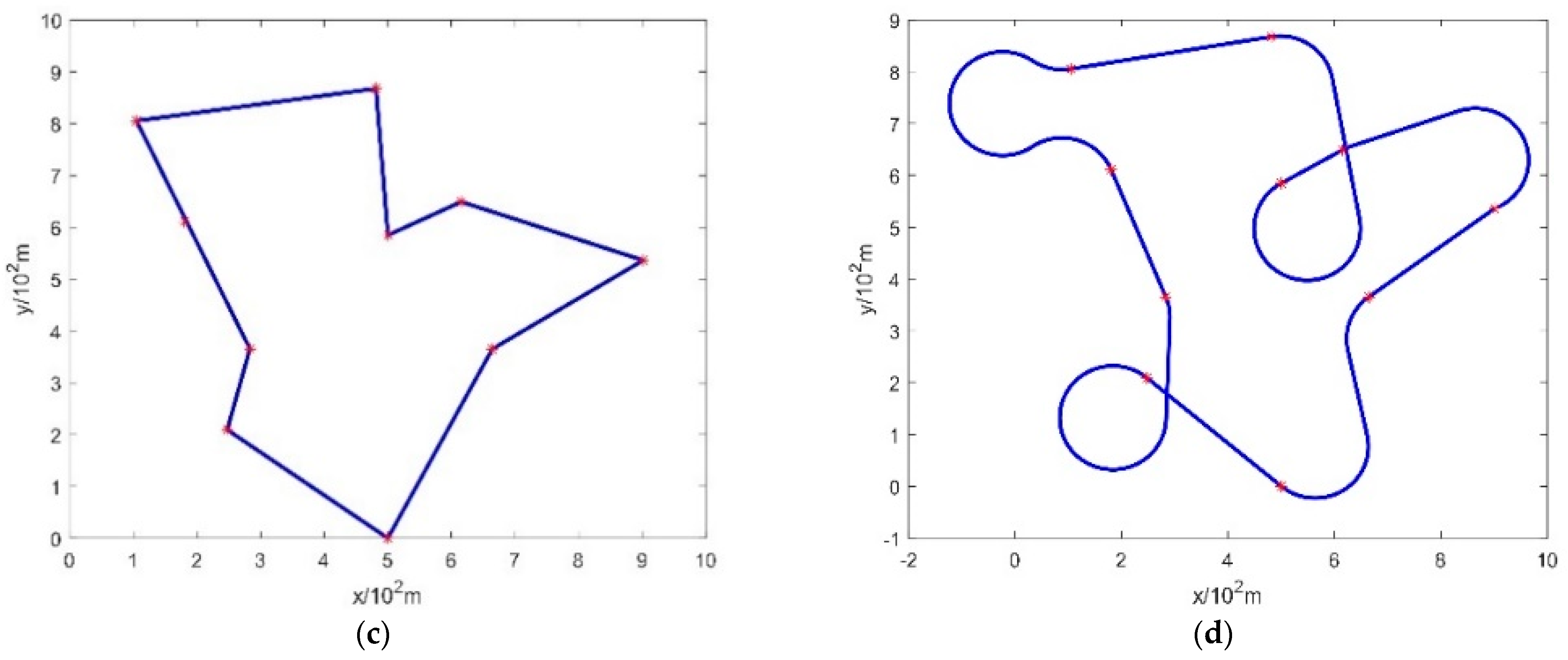
Figure 6 describes the planned trajectories utilizing the compensatory look-ahead algorithm, 2-opt look-ahead algorithm, alternating algorithm, and the ETSP model. The straight-line trajectory based on the ETSP algorithm serves as the reference standard under ideal conditions. It can be seen that the model trajectory with the compensatory look-ahead algorithm is notably smoother. Through the comparison of total mileage in Table 1, it can be affirmed that in dense regions, the compensatory look-ahead algorithm exhibits a minimum improvement of 12.9% compared to other algorithms. The increase in Euclidean distance is minimal, with a mere 33.2% increment. This is for the constraints imposed by the maximum curvature of the UAV in dense regions.
Table 2 displays the path-planning total mileage for different algorithms with 5, 10, 15, 20, and 25 target points. Through this table, it is discernible that the compensatory look-ahead algorithm is consistently better than other algorithmic models. This further substantiates the efficacy of the compensatory look-ahead algorithm in optimizing planning paths within dense regions, aligning seamlessly with our requirements.
Simulation 2: Using a single unmanned aerial vehicle (UAV) from a designated location, we conducted trajectory planning for 10 target points within a sparse region. Upon completing the tasks, the UAV returned to the starting point. We compared the travel distances of the planned paths using the compensatory look-ahead algorithm, 2-opt look-ahead algorithm, alternating algorithm, and ETSP model. Comparing the search efficiency of the four models.
Figure 7 describes the planned paths using the compensatory look-ahead algorithm, 2-opt look-ahead algorithm, alternating algorithm, and ETSP model within the sparse region. The straight-line trajectory based on the ETSP algorithm serves as the reference standard under ideal conditions. In comparison to simulation 1, the disparities among various algorithms in simulation 2 are not substantial. The reason is the vast distances between adjacent points in the sparse region, where subtle variations in heading angles have less impact compared to dense areas. The comparison of total mileage across different algorithms in Table 3 reveals that the compensatory look-ahead algorithm still yields the shortest planned path. In contrast to other algorithms, it boasts an improvement of up to 3.1%, with the increase in the shortest Euclidean distance merely reaching 1.4%.
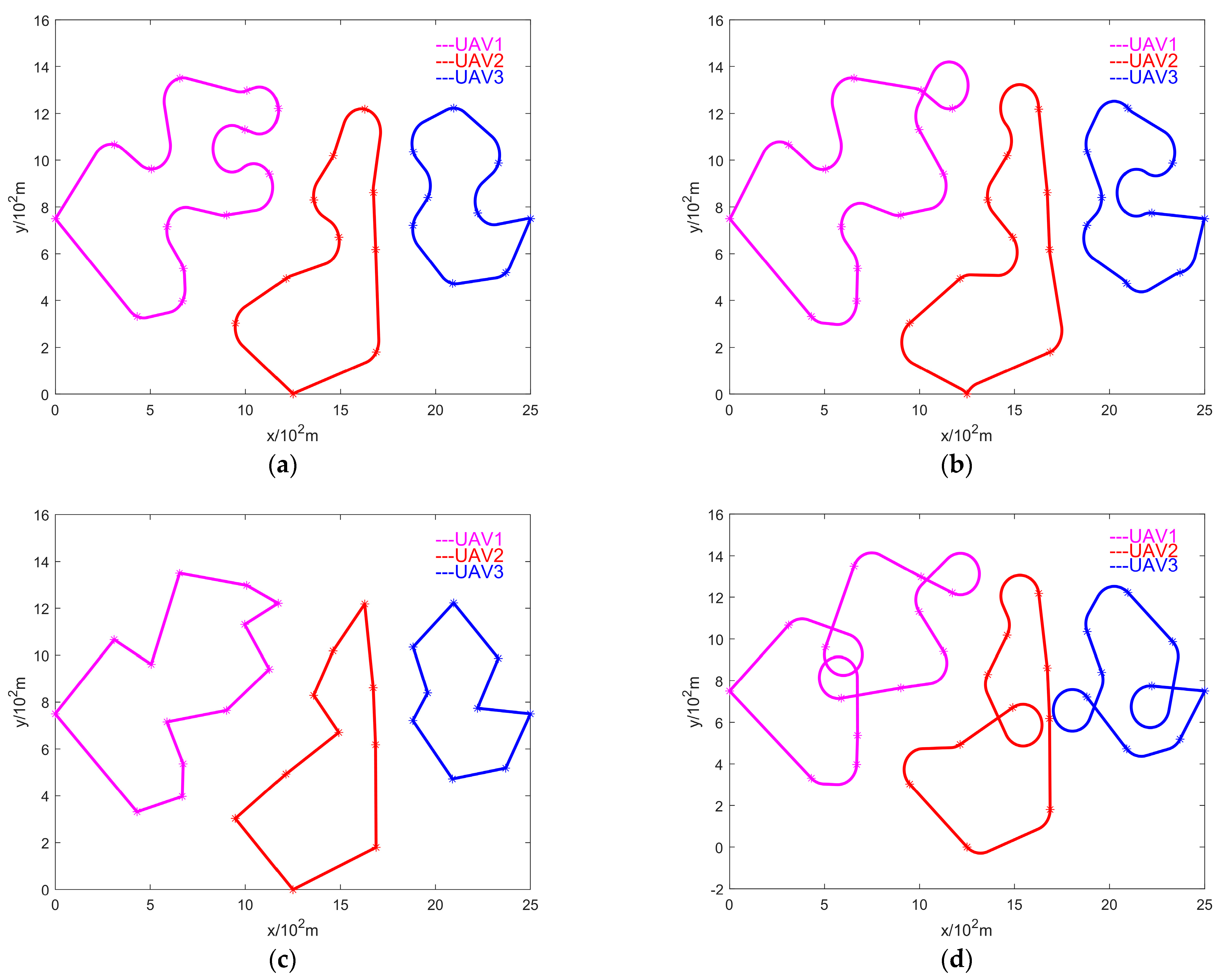
Simulation 3 involves three unmanned aerial vehicles (UAVs) taking off from a designated location and planning trajectories for 30 target points within a sparse region. After completing the tasks, the UAVs return to the starting point, a comparison of the travel distances of planned paths using the compensatory look-ahead algorithm, 2-opt look-ahead algorithm, alternating algorithm, and ETSP model. Comparing the search efficiency of the four models.
Figure 8 describes the trajectory planning for multiple unmanned aerial vehicles (UAVs) and various target points employing distinct algorithms for takeoff from the same points. The straight-line trajectory based on the ETSP algorithm serves as the reference standard under ideal conditions. From the illustration, it is evident that the compensatory look-ahead algorithm adeptly accomplishes the planning of paths for multiple UAVs and multiple targets. Notably, the total mileage of path planning for multiple UAVs and multiple targets using different algorithms is shown in Table 4. The compensatory look-ahead algorithm demonstrates an improvement of no less than 8.4% in the context of the multi-tasking, multi-UAV path-planning model.
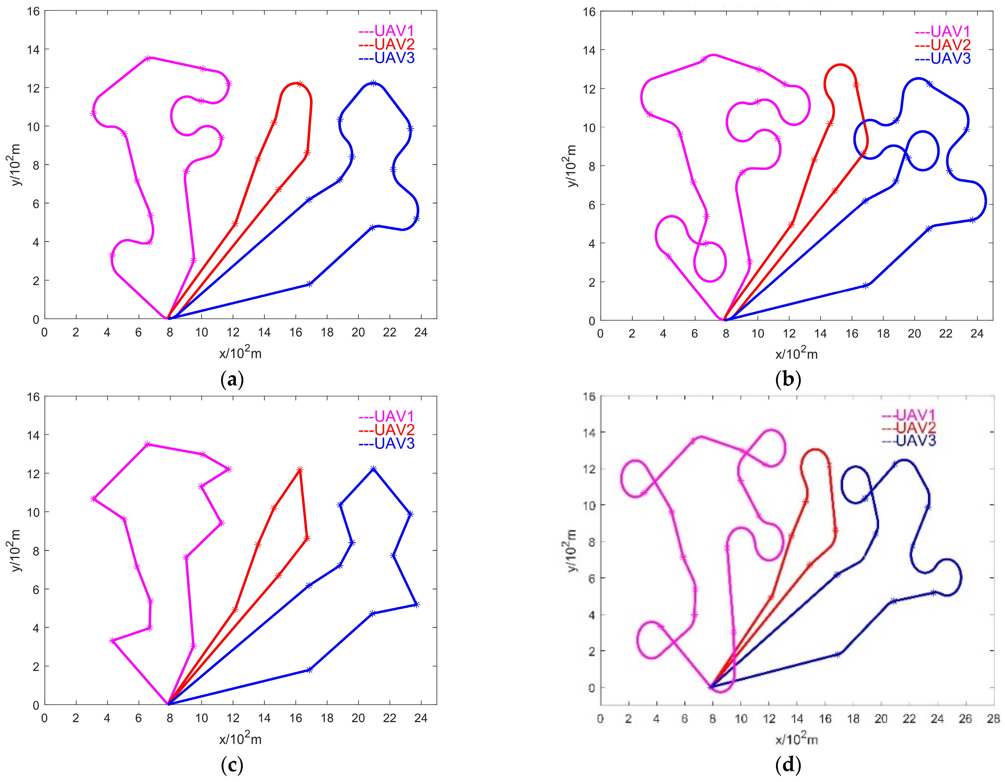
Simulation 4 involves three unmanned aerial vehicles (UAVs) taking off from different locations and planning trajectories for 30 target points within a sparse region. After completing the tasks, the UAVs return to the starting point, a comparison of the travel distances of planned paths using the compensatory look-ahead algorithm, 2-opt look-ahead algorithm, alternating algorithm, and ETSP model. Comparing the search efficiency of the four models.
Figure 9 shows the planned trajectory of multiple unmanned aerial vehicles (UAVs) taking off from different points using different algorithms. The straight-line trajectory based on the ETSP algorithm serves as the reference standard under ideal conditions. The three drones are takeoff at [0, 7.5], [12.5, 0], and [25, 7.5]. From the graph, it can be seen that the compensation look-ahead algorithm can complete the multi-objective path-planning task for multiple drones. Compared with the 2-opt look-ahead algorithm and the alternating algorithm, the planned trajectory is more in line with practical requirements, and the total distance of the planned path is the shortest. According to Table 5, it can be calculated that the compensation forward algorithm has a maximum improvement of 17.5% in the multi-task and multi-drone path-planning model compared to the alternating algorithm.

5. Conclusions

This article mainly studies the shortest-path planning problem of unmanned aerial vehicle formation under uncertain target sequences. Firstly, in order to improve the efficiency of collaborative search in drone clusters, a four-point optimized heading angle calculation method is proposed based on the horizon algorithm. On the basis of Ma et al.’s research, a general formula for calculating heading angle was proposed. Through the simulation data in the fourth section, it can be proven that our proposed compensation look-ahead algorithm reduces the situation where drones need to perform large-scale curve movements to reach the target point coordinates. Compared with existing algorithms, it has a maximum improvement of 12.9%. Secondly, for the large-scale formation problem, the ETSP algorithm is used to pre-allocate the large-scale target points to be allocated and a single drone, forming multiple subsets of target points. Then, the compensation foresight algorithm proposed in the second section is used to calculate each subset, ensuring that the computational scale of single-machine path planning is reduced while the scale of the target point set remains unchanged, achieving a balance between computational complexity and optimized path. The simulation data show that the EDTSP model proposed in this paper has at least 8.4% and 17.5% improvement in the sparse interval for takeoff from different points.

Author Contributions

Conceptualization, T.S. and W.S.; methodology, T.S.; software, T.S.; validation, T.S., W.S. and C.S.; formal analysis, T.S. and W.S.; investigation, T.S.; resources, T.S., W.S. and R.H.; data curation, T.S. and R.H.; writing—original draft preparation, T.S.; writing—review and editing, T.S. and W.S.; visualization, T.S.; supervision, T.S. and W.S.; project administration, W.S.; funding acquisition, W.S. All authors have read and agreed to the published version of the manuscript.

Funding

This paper was funded by the National Natural Science Foundation of China 62173330, 62371375; the Shaanxi Key R&D Plan Key Industry Innovation Chain Project (2022ZDLGY03-01); the China College Innovation Fund of Production, Education and Research (2021ZYAO8004); and the Xi’an Science and Technology Plan Project (2022JH-RGZN-0039).

Data Availability Statement

The raw data supporting the conclusions of this article will be made available by the authors upon request.

Conflicts of Interest

The authors declare no conflicts of interest.

References

  1. Richard, A.; Musa, A.A.; Bernard, E.; Jerry, A. Unmanned Aerial Vehicle (UAV) applications in coastal zone management—A review. Environ. Monit. Assess. 2021, 193, 154. [Google Scholar]
  2. Yang, Y.; Xiong, X.; Yan, Y. UAV Formation Trajectory Planning Algorithms: A Review. Drones 2023, 7, 62. [Google Scholar] [CrossRef]
  3. Caccia, M.; Bibuli, M.; Bono, R.; Bruzzone, G. Basic navigation, guidance and control of an unmanned surface vehicle. Auton. Robots 2008, 25, 349–365. [Google Scholar] [CrossRef]
  4. Cheikhrouhou, O.; Khoufi, I. A Comprehensive Survey on the Multiple Travelling Salesman Problem: Applications, Approaches and Taxonomy. Comput. Sci. Rev. 2021, 40, 100369. [Google Scholar] [CrossRef]
  5. Zhang, L.; Lu, Y.; Xu, S.; Feng, H. Multiple UAVs cooperative formation forming control based on back-stepping-like approach. J. Syst. Eng. Electron. 2018, 29, 154–160. [Google Scholar] [CrossRef]
  6. Wang, X.; Shen, L.; Liu, Z.; Zhao, S.; Cong, Y.; Li, Z.; Jia, S.; Chen, H.; Yu, Y.; Chang, Y.; et al. Coordinated flight control of miniature fixed-wing UAV swarms: Methods and experiments. Sci. China Inf. Sci. 2019, 62, 212204. [Google Scholar] [CrossRef]
  7. Muslimov, T.; Munasypov, R.A. Consensus-based cooperative control of parallel fixed-wing UAV formations via adaptive backstepping. Aerosp. Sci. Technol. 2021, 109, 106416. [Google Scholar] [CrossRef]
  8. Chen, Z.; Shima, T. Relaxed Dubins Problems through Three Points. In Proceedings of the 2019 27th Mediterranean Conference on Control and Automation (MED), Akko, Israel, 1–4 July 2019. [Google Scholar] [CrossRef]
  9. Ye, F.; Chen, J.; Tian, Y.; Jiang, T. Cooperative Task Assignment of a Heterogeneous Multi-UAV System Using an Adaptive Genetic Algorithm. Electronics 2020, 9, 687. [Google Scholar] [CrossRef]
  10. Avla, K.; Frazzoli, E.; Bullo, F. On the point-to-point and traveling salesperson problems for Dubins’ vehicle. In Proceedings of the 2005 American Control Conference, Portland, OR, USA, 8–10 June 2005; IEEE: Piscataway, NI, USA, 2005. [Google Scholar] [CrossRef]
  11. Xin, J.; Zhong, J.; Li, S.; Sheng, J.; Cui, Y. Greedy Mechanism Based Particle Swarm Optimization for Path Planning Problem of an Unmanned Surface Vehicle. Sensors 2019, 19, 4620. [Google Scholar] [CrossRef]
  12. Ma, X.; Castanon, D.A. Receding Horizon Planning for Dubins Traveling Salesman Problems. In Proceedings of the 45th IEEE Conference on Decision and Control, San Diego, CA, USA, 13–15 December 2006; IEEE: Piscataway, NI, USA, 2007. [Google Scholar] [CrossRef]
  13. Isaiah, P.; Shima, T. Motion planning algorithms for the Dubins Travelling Salesperson Problem. Automatica 2015, 53, 247–255. [Google Scholar] [CrossRef]
  14. Cohen, I.; Epstein, C.; Isaiah, P.; Kuzi, S.; Shima, T. Discretization-Based and Look-Ahead Algorithms for the Dubins Traveling Salesperson Problem. IEEE Trans. Autom. Sci. Eng. 2017, 14, 383–390. [Google Scholar] [CrossRef]
  15. Johnson, D.S.; Mcgeoch, L.A. The Traveling Salesman Problem: A Case Study in Local Optimization. In Local Search in Combinatorial Optimization; John Wiley and Sons: London, UK, 1997. [Google Scholar]
  16. Savla, K.; Frazzoli, E.; Bullo, F. Traveling salesperson problems for the Dubins vehicle. IEEE Trans. Autom. Control 2008, 53, 1378–1391. [Google Scholar] [CrossRef]
  17. Zhu, X.; Lai, J.; Chen, S. Cooperative Location Method for Leader-Follower UAV Formation Based on Follower UAV’s Moving Vector. Sensors 2022, 22, 7125. [Google Scholar] [CrossRef] [PubMed]
  18. Zhang, X.; Chen, J.; Xin, B.; Peng, Z. A memetic algorithm for path planning of curvature-constrained UAVs performing surveillance of multiple ground targets. Chin. J. Aeronaut. 2014, 27, 622–633. [Google Scholar] [CrossRef]
  19. Li, F.; Lan, Y. A drone with a combination of dual rotors and fixed wings. Acad. J. Eng. Technol. Sci. 2021, 4, 55–58. [Google Scholar]
  20. Drchal, J.; Faigl, J.; Vana, P. WiSM: Windowing Surrogate Model for Evaluation of Curvature-Constrained Tours with Dubins Vehicle. IEEE Trans. Cybern. 2022, 52, 1302–1311. [Google Scholar] [CrossRef] [PubMed]
  21. Boissonnat, D.; Bui, X.-N. Accessibility Region for a Car That Only Moves Forwards along Optimal Paths. Rapport de Recherche 2181. Ph.D. Thesis, INRIA, Le Chesnay-Rocquencourt, France, January 1994. [Google Scholar]
  22. Yal, C.; Markov, K.N. Dubins path via optimal control theory. Comput. Optim. Appl. 2017, 68, 719–747. [Google Scholar] [CrossRef]
  23. Li, L.; Shi, D.; Jin, S.; Yang, S.; Zhou, C.; Lian, Y.; Liu, H. Exact and Heuristic Multi-Robot Dubins Coverage Path Planning for Known Environments. Sensors 2023, 23, 2560. [Google Scholar] [CrossRef] [PubMed]
  24. Athans, M.; Falb, P.L. Optimal Control; McGraw-Hill: New York, NY, USA, 1966. [Google Scholar]
  25. Shkel, A.M.; Lumelsky, V.J. Classification of the Dubins’ set. Robot. Auton. Syst. 2001, 34, 179–202. [Google Scholar] [CrossRef]
  26. Sussmann, H.J.; Tang, W. Shortest Paths for the Reeds-Shepp Car: A Worked Out Example of the Use of Geometric Techniques in Nonlinear Optimal Control; Report SYCON-91-10; Rutgers University: New Brunswick, NJ, USA, 1991. [Google Scholar]
  27. Bui, X.N.; Boissonnat, J.D.; Soueres, P.; Laumond, J.P. Shortest path synthesis for Dubins non-holonomic robot. In Proceedings of the 1994 IEEE International Conference on Robotics and Automation, San Diego, CA, USA, 8–13 May 1994; IEEE: Piscataway, NI, USA, 1994. [Google Scholar] [CrossRef]
  28. Wenyu, C.; Meiyan, Z.; Yahong, Z. Task Assignment and Path Planning for Multiple Autonomous Underwater Vehicles Using 3D Dubins Curves. Sensors 2017, 17, 1607. [Google Scholar] [CrossRef]
  29. Cons, M.S.; Shima, T.; Domshlak, C. Integrating Task and Motion Planning for Unmanned Aerial Vehicles. Unmanned Syst. 2014, 2, 1938. [Google Scholar] [CrossRef]
  30. Carter, A.E.; Ragsdale, C.T. A new approach to solving the multiple traveling salesperson problem using genetic algorithms. Eur. J. Oper. Res. 2006, 175, 246–257. [Google Scholar] [CrossRef]
  31. Edison, E.; Shima, T. Integrated task assignment and path optimization for cooperating uninhabited aerial vehicles using genetic algorithms. Comput. Oper. Res. 2011, 38, 340–356. [Google Scholar] [CrossRef]
  32. Pontryagin, L.S.; Boltyanskii, V.G.; Gamkrelidze, R.V.; Mischenko, E.F. The Mathematical Theory of Optimal Processes; John Wiley & Sons: Hoboken, NJ, USA, 1962. [Google Scholar]
  33. Noon, C.E.; Bean, J.C. A Lagrangian Based Approach for the Asymmetric Generalized Traveling Salesman Problem. Oper. Res. 1991, 39, 623632. [Google Scholar] [CrossRef]
  34. Yafei, D.; Quanwang, W.; Junhao, W. An improved shuffled frog-leaping algorithm for the minmax multiple traveling salesman problem. Neural Comput. Appl. 2021, 33, 17057–17069. [Google Scholar]
  35. Tsai, H.C.; Hong, Y.W.P.; Sheu, J.P. Completion Time Minimization for UAV-Enabled Surveillance Over Multiple Restricted Regions. IEEE Trans. Mob. Comput. 2023, 22, 6907–6920. [Google Scholar] [CrossRef]
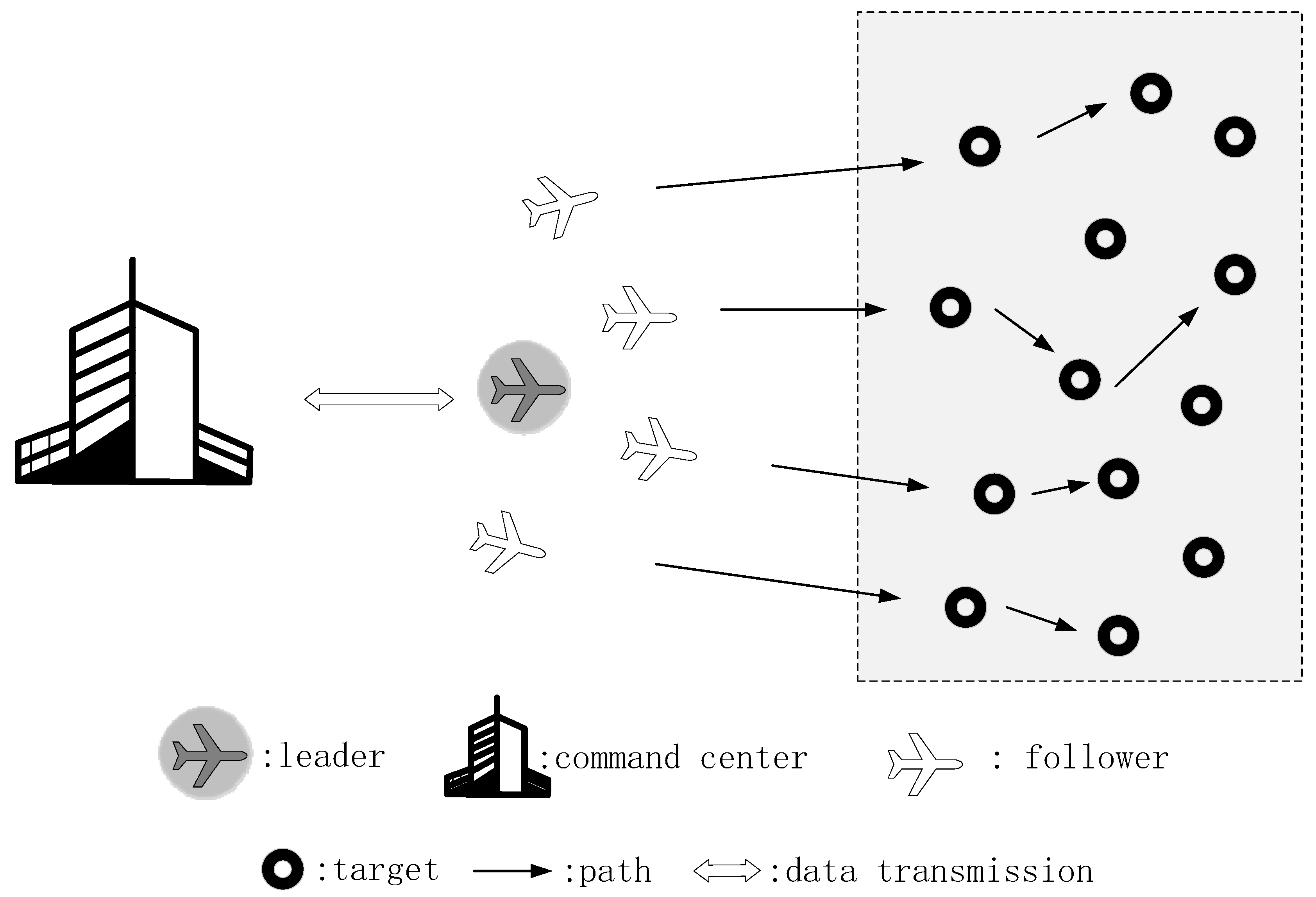
Figure 1. Typical scenarios for task path planning of drone swarms.
Drones 08 00251 g001
Figure 2. Schematic diagram of the optimal path.
Drones 08 00251 g002
Figure 3. The schematic diagram of the optimal path.
Drones 08 00251 g003
Figure 4. Illustration of the solution process for the heading angle at the midpoint.
Drones 08 00251 g004
Figure 5. EDTSP model allocation flowchart.
Drones 08 00251 g005
Figure 6. Planning trajectory maps using different algorithms in the dense region: (a) compensation look-ahead algorithm; (b) 2-opt look-ahead algorithm; (c) ETSP; (d) alternating algorithm.
Drones 08 00251 g006aDrones 08 00251 g006b
Figure 7. Planning trajectory maps using different algorithms in the sparse region: (a) compensation look-ahead algorithm; (b) 2-opt look-ahead algorithm; (c) ETSP; (d) alternating algorithm.
Drones 08 00251 g007
Figure 8. Trajectory maps for drone formation planning using different algorithms for takeoff from the same points: (a) compensation look-ahead algorithm; (b) 2-opt look-ahead algorithm; (c) ETSP; (d) alternating algorithm.
Drones 08 00251 g008
Figure 9. Trajectory maps for drone formation planning using different algorithms for takeoff from different points: (a) compensation look-ahead algorithm; (b) 2-opt look-ahead algorithm; (c) ETSP; (d) alternating algorithm.
Drones 08 00251 g009
Table 1. Total mileage of path planning in dense areas using different algorithms.
Compensation Look-Ahead Algorithm2-Opt Look-Ahead AlgorithmAlternating AlgorithmETSP
Total mileage (102 m)36.769542.224848.016427.6005
Table 2. Total mileage of path planning with different target points for different algorithms in dense regions.
Target Number (Total Mileage 102 m)Compensation
Look-Ahead Algorithm
2-Opt Look-Ahead
Algorithm
Alternating AlgorithmETSP
523.985124.841526.856222.3707
1036.769542.224848.016427.6005
1547.158455.512460.861235.2885
2056.514764.361576.157437.7948
2565.184574.612487.145141.1114
Table 3. Total mileage of path planning in sparse areas using different algorithms.
Compensation Look-Ahead Algorithm2-Opt Look-Ahead AlgorithmAlternating AlgorithmETSP
Total mileage (102 m)36.769542.224848.016427.6005
Table 4. The total mileage of path planning for multiple UAVs and multiple targets using different algorithms starting from the same point.
Compensation Look-Ahead Algorithm2-Opt Look-Ahead AlgorithmAlternating AlgorithmETSP
Total mileage (102 m)141.17154.115159.702109.995
Table 5. Total mileage of path planning for multiple UAVs and multiple targets using different algorithms starting from different points.
Compensation Look-Ahead Algorithm2-Opt Look-Ahead AlgorithmAlternating AlgorithmETSP
Total mileage (102 m)114.1742124.1158138.411394.7549
Disclaimer/Publisher’s Note: The statements, opinions and data contained in all publications are solely those of the individual author(s) and contributor(s) and not of MDPI and/or the editor(s). MDPI and/or the editor(s) disclaim responsibility for any injury to people or property resulting from any ideas, methods, instructions or products referred to in the content.