Abstract
To address collision challenges between multi-UAVs (unmanned aerial vehicles) during obstacle avoidance, a novel formation control method is proposed. Leveraging the concept of APF (artificial potential field), the proposed approach integrates UAV maneuver constraints with a consensus formation control algorithm, optimizing UAV velocities through the particle swarm optimization (PSO) algorithm. The optimal consensus control algorithm is then employed to achieve the optimal convergence rate of the UAV formation. To mitigate the limitations of traditional APF, a collinear force deflection angle is introduced, along with an obstacle avoidance method aimed at preventing UAVs from being trapped in locally optimal solutions. Additionally, an obstacle avoidance algorithm based on virtual force fields between UAVs is designed. Comparative analysis against the basic algorithm demonstrates the effectiveness of the designed optimal consensus algorithm in improving formation convergence performance. Moreover, the improved APF resolves local optimal solution issues, enabling UAVs to effectively navigate around obstacles. Simulation results validate the efficacy of this method in achieving multi-UAV formation control while effectively avoiding obstacles.
1. Introduction
The advancement of UAV (unmanned aerial vehicle) technology has facilitated its widespread utilization across various civil and military domains, including activities such as farmland seeding, forest search and rescue, border monitoring, battlefield surveillance, and electronic countermeasures, among others. However, the intricate nature of tasks and environments poses challenges for single-UAV operations, necessitating the exploration of multi-UAV collaboration. This paradigm has garnered increasing attention due to its notable attributes, including heightened efficiency, robustness, multifunctionality, and scalability. Given the extensive application prospects and significant operational advantages associated with multi-UAVs, research on multi-UAV formation control technology has emerged as a focal point of investigation.
Significant advancements have been made in the research of multi-UAV formation control technology. Control structures in this domain are typically classified into three categories: centralized, decentralized, and distributed. Among these, the consensus algorithm within the distributed control structure is particularly notable for its low communication load, minimal computational requirements, and strong robustness, making it a subject of extensive scholarly discussion [1].
In the field of consensus formation control for multi-UAVs, several key contributions have emerged. He et al. [2] proposed a consensus control algorithm designed for high-speed UAV swarms, which utilizes navigation feedback from other UAVs to maintain formation control. Xue and Wu [3] developed a fuzzy-based sliding-mode control integrated with the consensus method for heterogeneous multiagent systems, which include both UAVs and unmanned vehicles, ensuring formation convergence. Zhen et al. [4] introduced a consensus control scheme based on multivariate model adaptive control to address the challenges of formation flight under conditions of uncertain parameters and external disturbances. Fu et al. [5] combined a virtual center and consensus control algorithm to achieve formation control of quadrotor UAVs and integrated the consensus-based auction algorithm (CBAA) for formation reconfiguration. Tao et al. [6] designed an improved consistency control algorithm to address issues of asymmetric communication interference and network congestion, enabling the formation control of multi-UAVs by constraining their motion states. In terms of the convergence performance of UAVs, Yue et al. [7] introduced finite-time stability theory to enable the system to reach the desired formation in finite time and obtain a settling time related to the initial state. Gu et al. [8] studied a UAV swarm formation reconfiguration method based on consistency theory and sliding mode control. Simulation experiments revealed that the proposed method can improve the convergence performance of UAV swarm reconfiguration.
Building on multi-UAV formation control technology and combining it with other algorithms can achieve effective UAV obstacle avoidance and collision avoidance control. Scholars have categorized multi-UAV obstacle and collision avoidance technologies into two main groups: optimization algorithms, such as particle swarm optimization, ant colony optimization, and A* algorithms [9,10,11], and local obstacle avoidance algorithms, including artificial potential field (APF), dynamic-window approach (DWA), and model predictive control (MPC) [12,13,14,15]. The APF method is particularly notable for its simple implementation, fast response, and good adaptability. Consequently, some researchers have combined the APF method with consensus control algorithms to address UAV obstacle and collision avoidance challenges.
Fang et al. [16] proposed a segmented APF trajectory planning method combined with consensus control to address the trajectory planning problem for UAVs in different states. This method segments the potential field to meet set motion constraints and adjusts the trajectory point velocity using APF, resulting in a smoother trajectory at local oscillation points. Simulation results indicate that this algorithm produces smoother trajectories than traditional methods while meeting motion constraints and preventing UAV collisions. Huang et al. [17] improved the traditional APF method by developing a smoothed potential field approach for trajectory planning under various UAV states. This improved smoothed APF method, combined with the second-order consensus method, demonstrated its effectiveness through the formation and collision avoidance simulations involving both static and dynamic obstacles. Wang et al. [18] tackled obstacle avoidance and position–velocity consensus issues for UAV swarms in a 3D obstacle environment. They enhanced the APF method by incorporating coordination gain and planning angle influences, proposing a method that combines the improved APF with the second-order consensus method. Simulation experiments showed that this method quickly restored the desired formation following obstacle and collision avoidance maneuvers. Wu et al. [19] advanced the consensus method by increasing UAV maneuverability constraints and, using the improved consensus method and particle swarm optimization (PSO) algorithm, proposed predictive control models for UAV motion under various initial conditions, thereby achieving efficient obstacle avoidance for both static and dynamic obstacles. Wu et al. [20] also proposed a hybrid genetic simulated annealing approach combined with a consensus protocol control algorithm. This approach rapidly determines UAV formation positions during reconfiguration, reduces reconfiguration time, and prevents collisions. Zhang et al. [21] developed a control method integrating the consensus approach and improved APF to achieve collision avoidance for UAV swarms during high-speed flight. Liu et al. [22] introduced a distributed optimal control method based on reinforcement learning for heterogeneous UAV formations. This method allows for the online acquisition of optimal control inputs without requiring detailed knowledge of follower UAV dynamics, ensuring stable control of the UAV swarm. Yang et al. [23] proposed an optimization algorithm based on single- and double-integral models for the optimal control of cluster motion within a finite period. This algorithm achieves cluster convergence within a finite time and minimizes the intelligent system’s performance index. Experimental simulations confirm that the algorithm maintains the minimum energy function under certain conditions, achieving the optimal cluster formation time. Yang et al. [24] introduced a linear quadratic regulator optimization method based on consensus control for optimal control problems in heterogeneous unmanned systems. Bai et al. [25] designed a higher-order consensus control algorithm for quadrotor UAVs with a fixed control topology. To achieve the global optimal solution for attitude control, they proposed an attitude control algorithm based on variable-weight hybridization, with experiments demonstrating the algorithm’s ability to dynamically adjust inertia weights and coefficients to control the influence degree. Zhu et al. [26] proposed a connectivity-maintained UAV formation control algorithm and a speed-based artificial potential field algorithm to facilitate the formation and obstacle avoidance control of multiple UAVs in complex environments. These advancements collectively enhance the capabilities of multi-UAVs, enabling them to navigate and operate efficiently in diverse and challenging scenarios.
The formation control and obstacle avoidance of multi-UAVs have been extensively studied, as evidenced by the aforementioned references. However, there is a noticeable gap in the literature concerning the convergence performance of multi-UAV formation. This paper addresses this gap by first optimizing the control inputs of UAVs using an optimal algorithm. Additionally, the speed of the UAVs is further optimized using the PSO algorithm to minimize the time required for multi-UAV formation. Finally, to address the obstacle avoidance challenges in multi-UAV systems, this study implements an improved APF method to achieve collaborative obstacle avoidance control in UAV formations.
2. UAV Kinematics Model and Consensus Control Theory
To streamline the UAV kinematics model, this paper focuses on the motion state of UAVs within a two-dimensional plane. The maneuvering parameters are constrained based on the practical application environment. Subsequently, a formation control algorithm is developed leveraging consensus theory principles.
The commonly used kinematics model of UAVs can be described as follows [20]:
where is the position of UAV ; is the heading angle of UAV ; and are the velocity components in vertical and horizontal directions of UAV ; and are the acceleration components in vertical and horizontal directions of UAV ; and is the horizontal angular velocity of the UAV .
To simplify the study of multi-UAV formation control, the kinematics model of UAVs in a two-dimensional plane can be simply described as follows:
where are the velocity components in and directions of UAV , and and are the acceleration components in and directions of UAV . According to the actual flight situation of the UAV, the same constraints are proposed for the velocity and acceleration of each UAV in the multi-UAV formation.
In Equation (3), the range of variation for velocity and acceleration components is provided.
The distributed consensus algorithm stands out as a commonly employed method in multi-UAV formation control. The simplified kinematics model of UAVs can be described by the following differential equation:
where is the system state quantity, and is the control input quantity. The second-order consensus algorithm can be expressed as follows:
Equation (5) represents a second-order consensus control algorithm that regulates the velocity and position of the UAV to achieve state consensus, where denotes the positive gain coefficient of the first-order state variable, and represents the element of the adjacency matrix indicating the communication connection between UAV and . When there is communication between the UAVs, ; otherwise, . It is assumed that , which implies that UAV in the formation can obtain information about UAV . In Figure 1, UAV 1 and UAV 2 can communicate with each other; UAV 2 and UAV 3 are unable to communicate at all; and UAV 3 can only receive information from UAV 1 but cannot transmit its information to UAV 1.
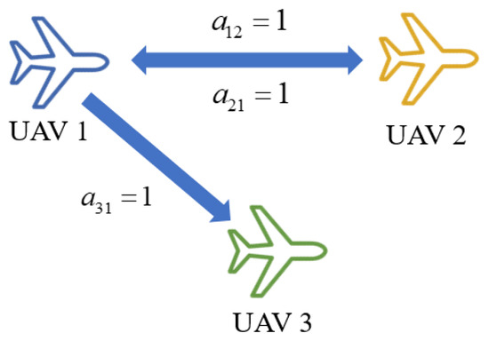
Figure 1.
UAV communication schematic.
Meanwhile, to enable the multi-UAV system to form the desired formation, the relative distance between the UAVs is utilized to construct the relative position matrix, as illustrated in Equation (6).
where is the distance between the UAV and . When the UAVs form a formation, the following conditions need to be met:
Equation (7) shows that when the UAV swarm tends to be stable, the relative position between the UAVs needs to tend to the relative distance of (6), and the velocity between the UAVs needs to tend to be consistent. In other words, and . The second-order consensus algorithm of Equation (5) can be expressed as follows:
The consensus algorithm of Equation (8) enables the multi-UAV system to achieve the expected formation; however, it does not specify the flight velocity of the UAVs. To meet the actual flight requirements, based on Equation (8) and combined with the autopilot command model, the UAVs can fly at the specified velocity while maintaining the expected formation. Based on the difference between the current velocity of the UAV i and the desired velocity , the acceleration required for the UAV to reach the desired velocity can be obtained. This is represented by the velocity state feedback term , where is the gain coefficient of the feedback term. Incorporating this into Equation (8), the improved consensus algorithm can be expressed as follows:
Equation (9) is a second-order consensus formation control algorithm that integrates formation information and feedback of a desired motion state. The feedback term adds control to the algorithm in Equation (8) to achieve the desired motion state, while the formation information ensures that the multi-UAVs form the desired formation according to a specified matrix of relative positions, where are the feedback data of the current UAV motion, are the expected velocity in and directions, are the control coefficients in and directions, and , are the distance conversion parameters in and directions.
3. Formation Control Based on Optimal Consensus and Particle Swarm Optimization Algorithm
3.1. Multi-UAV Formation Control Method
To achieve the optimal convergence of the UAV velocity, we optimized the UAV velocity using the optimal consensus control and PSO algorithms. The first-order optimal consensus control algorithm can be described as follows:
where are the positional consensus weights and control consumption. The improved optimal consensus algorithm based on first-order optimal consensus control can be expressed as follows:
where are the velocity-consistent weights in the directions, and the remaining parameters are consistent with those in (9).
The PSO algorithm addresses the global optimization problem by leveraging information sharing among individuals. In this study, both velocity and acceleration were utilized as parameters to determine the optimal velocity at a given moment. The updated model for the UAV’s velocity can be expressed as follows:
where are the velocity and acceleration at the time , is a non-negative number representing inertia weights, are the learning rates of the particles converging to the corresponding states, are random numbers from 0 to 1, and are the locally optimal and globally optimal velocity. The flow of the algorithm is shown in Figure 2.
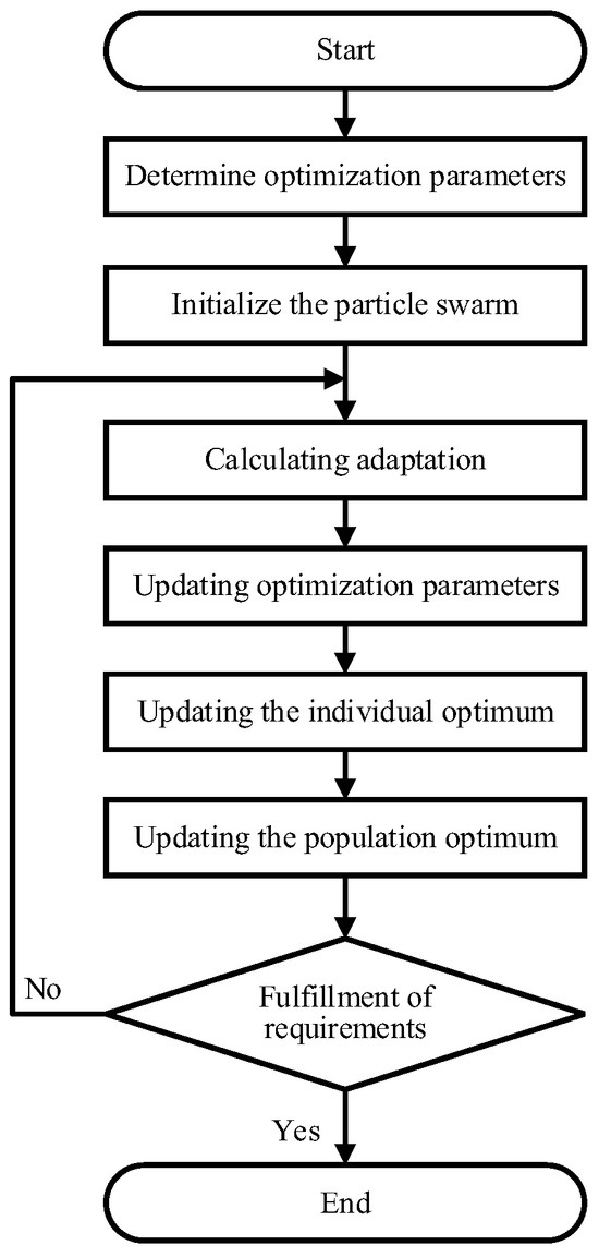
Figure 2.
Flow chart of PSO algorithm.
The optimization of velocity using the PSO algorithm is structured into seven distinct steps as follows:
Step 1: Identify the optimization’s objectives and parameters;
Step 2: Initialize the particle swarm with current parameter data;
Step 3: Calculate the fitness or adaptation of each particle in the swarm;
Step 4: Update the particles’ velocities and accelerations according to specific formulas and optimize them within the set constraints;
Step 5: Evaluate the updated individual best value for each particle based on its new fitness and compare this value to its previous best. Retain the superior individual best value;
Step 6: Compare the best individual values within the swarm to the historical optimal value of the entire swarm and retain the best population value;
Step 7: Evaluate the termination criteria for the optimization process. If the criteria are met, conclude the optimization; otherwise, return to Step 3 and continue iterating.
Equation (11) is combined with the PSO algorithm to obtain the optimized acceleration and velocity as follows:
where is the consistency control of Equation (11); is the acceleration in the PSO algorithm; is the next velocity calculated under the consistency control; is the next velocity obtained by the PSO algorithm; and , are the optimized UAV acceleration and velocity, respectively.
3.2. Simulation Results
3.2.1. Improved Optimal Consensus Formation Simulation Based on PSO Algorithm
(a) Feasibility Simulation of the Improved Algorithm
In this section, the example of six UAVs arranged in a triangular formation is used to illustrate the application of the formation control methods discussed. The maneuvering constraint parameters for each UAV are detailed in Table 1. This table outlines the specific constraints and parameters that govern the behavior and operational limits of the UAVs within the formation, ensuring that their movements are coordinated and adhere to predefined guidelines.

Table 1.
UAV maneuvering constraint parameters.
The communication topology adjacency matrix of the six UAVs is as follows:
The relative position matrices of the desired formation alignments are, respectively, as follows:
Multi-UAV formation control is simulated and analyzed based on the consensus control algorithm of (9), where the desired motion state of the UAV is , , and its initial motion parameters are shown in Table 2. The parameters of the consensus control algorithm are set to , . The parameters related to the PSO algorithm are set to , . The simulation results obtained are shown in Figure 3, Figure 4, Figure 5 and Figure 6.

Table 2.
Initial motion parameters of the UAV.
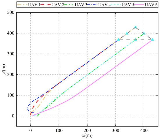
Figure 3.
Trajectory of UAVs.
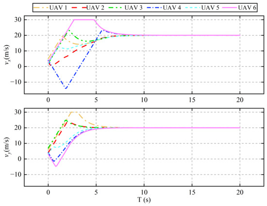
Figure 4.
Velocity of UAVs.
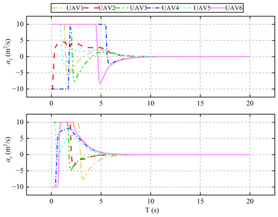
Figure 5.
Acceleration of UAVs.
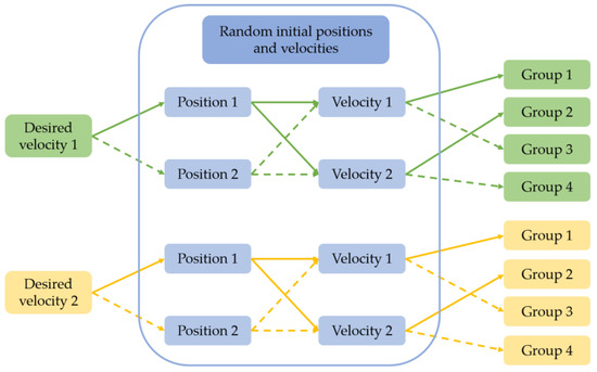
Figure 6.
Simulation groupings.
Figure 3 displays the formation flight trajectories of the six UAVs, demonstrating that with the implemented control algorithm, the UAVs are able to successfully form and maintain the desired formation. Figure 4 and Figure 5 detail the variations in UAV velocity and acceleration, respectively. These figures show that the velocity in the x direction converges to the desired velocity at approximately 10 s, with its corresponding acceleration converging to 0. Similarly, the velocity in the y direction reaches the desired velocity around 7 s, with its corresponding acceleration also converging to 0. These simulation results confirm that the UAVs can effectively navigate using the designed formation control algorithm. Moreover, they maintain formation stability under the velocity settings, adhering to the constraints imposed by the velocity feedback term. This demonstrates the algorithm’s ability to ensure precise and stable control of UAV formations under dynamic conditions.
(b) Flight Trajectory Simulation with Different Parameters
In part (b), the trajectory simulation comparison under two different desired velocities is performed by setting two random initial positions and two sets of random initial velocities. In this case, the desired velocities set are , and , ; the range of the random initial position is , and the range of the random initial velocity is . The simulation groupings are shown in Figure 6. The simulation results are shown in Figure 7.
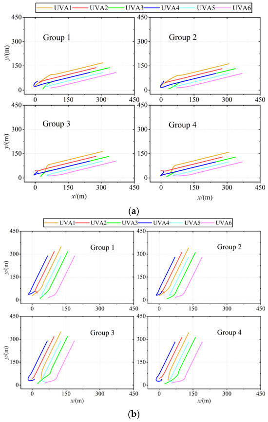
Figure 7.
Flight trajectory with different parameters: (a) trajectory with desired velocity 1; (b) trajectory with desired velocity 2.
Figure 7 illustrates the trajectories of UAVs under two sets of desired velocities and varying initial parameters, demonstrating that the randomly generated initial positions and velocities have minimal impact on the trajectory of the UAVs when the desired velocities are consistent. The trajectory trends remain essentially the same under these conditions. However, when the desired velocities differ, the trajectories diverge even if the initial positions and velocities are identical. This variation is attributed to the fact that the trajectory formation is influenced by the desired velocity. Nevertheless, under the guidance of algorithm (11), the UAV velocity converges to the desired velocity, as dictated by the feedback term. Thus, in formation control, the trajectory of UAVs is primarily influenced by the desired velocity, with initial positions and velocities having a lesser impact on the trajectory outcome.
3.2.2. Formation Convergence Time Comparison Simulation
(a) Comparative Simulation of Formation Algorithms
This section details the comparative simulations conducted to evaluate the improved algorithm against an unoptimized version. These simulations are executed with six random communication topologies and two different queue configurations. In the second set of experiments, the relative position matrices for the desired formation alignments are set as follows:
Figure 8 displays the simulation outcomes for optimized and non-optimized algorithms applied to multi-UAVs in two different formations, each with six sets of random communication topologies. The results show that, compared to the non-optimized algorithm, the optimized algorithm significantly shortens the convergence time for the same formation, irrespective of the random communication topology utilized by the multi-UAVs. These findings affirm that the algorithm developed in this study effectively reduces the convergence time required for UAV formation control.
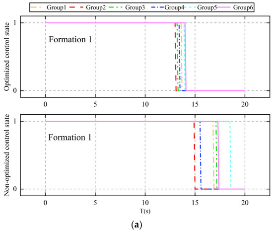
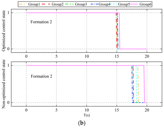
Figure 8.
Comparison of algorithm convergence times: (a) comparison of algorithm convergence times under formation 1; (b) comparison of algorithm convergence times under formation 2.
(b) Coefficient Comparison Simulation of Improved Algorithms
This section involves simulating five different conditions to evaluate the effects of feedback term coefficients and distance conversion coefficients on the convergence time of multi-UAV formation. The settings for the coefficients of the improved algorithm are detailed in Table 3. The results of these simulations are depicted in Figure 9, providing a visual and quantitative analysis of how varying coefficients influence the performance of the formation control algorithm.

Table 3.
Comparison coefficient settings.
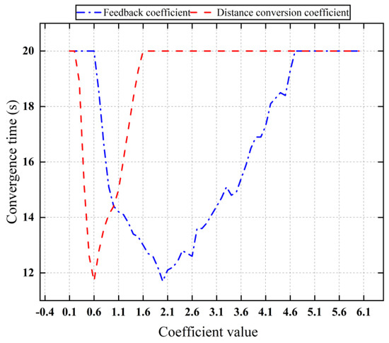
Figure 9.
Convergence time of different coefficients.
Figure 9 illustrates the convergence times of UAV velocities for various coefficient settings. The graph indicates that as the coefficients increase, the convergence performance of the algorithm initially improves but subsequently diminishes. Optimal convergence performance is observed when the feedback coefficient is set at 0.6 and when the distance conversion coefficient is at 2.0. These settings demonstrate the most effective balance in the algorithm, optimizing the UAVs’ ability to quickly achieve the desired formation speeds while maintaining stability and accuracy in their trajectories.
4. Collaborative Obstacle Avoidance Method Based on Improved APF
Upon detecting an obstacle, multi-UAVs must either modify or disband their formation to navigate around the obstacle, subsequently reconfiguring the formation once the obstacle has been avoided. The APF method facilitates obstacle avoidance by creating virtual forces between UAVs and obstacles. This involves both repulsive and attractive forces between UAVs and obstacles; however, only repulsive forces are operational between UAVs themselves. When two UAVs come within a predefined collision avoidance distance, repulsive forces are generated to ensure they maintain a safe separation. Similarly, when a UAV approaches an obstacle, it encounters a repulsive force generated by the obstacle, steering the UAV away to prevent a collision.
4.1. Improved APF Based on Small-Angle Deflection
After the UAV enters the obstacle avoidance range, it needs to be controlled by the APF method for obstacle avoidance, as shown in Figure 10.
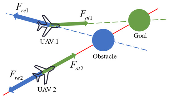
Figure 10.
Schematic diagram of APF.
where is the attraction of the goal to the UAV and is the repulsion of the obstacle to the UAV. In the APF method, the attractive potential field model can be described as follows:
where is the gravitational potential field coefficient, and is the distance between the UAV and the target point; then, its gravitational force can be expressed as a negative gradient force of the gravitational potential field function as follows:
The repulsive potential field model of the conventional APF method is shown in the following equation:
where is the repulsive potential field coefficient, is the distance of the UAV from the obstacle, and is the obstacle avoidance range. When the obstacle is in line with the UAV navigation, the UAV will fall into the local optimal solution; to solve the local optimal problem, the traditional repulsive potential field model is improved.
When an obstacle moves in a straight line along the same path as a UAV, the UAV can become trapped in a local optimal solution, as demonstrated by UAV 2 in Figure 10. To address this issue of local optima, the traditional repulsive potential field model was enhanced by adjusting the direction of the repulsive force with a small angle. This modification is illustrated in Figure 11.
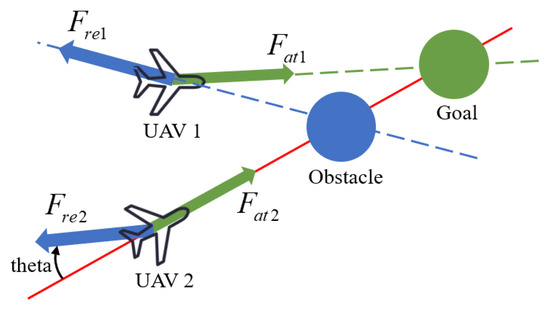
Figure 11.
Schematic diagram of the improved repulsive force model.
In Figure 11, is the offset angle. The improved APF model is as follows:
where is introduced; the distance factor between the UAV and the target point is added; and although the repulsive potential field increases greatly, the distance decreases to solve the target unreachable problem. Meanwhile, when the UAV is caught in the local optimal solution, the local optimal solution problem is solved by deflecting a small angle, which changes the obstacle and UAV sailing colinear situation.
Then, its corresponding repulsive force can be expressed as the negative gradient force of the repulsive potential field.
Then, the sum of repulsive forces on the drone can be expressed as follows:
where is the number of obstacles, and is the repulsive force between the UAV and the obstacle .
To avoid collision between UAVs, we designed a collision avoidance algorithm between UAVs using the APF method, which increases the repulsive force between UAVs when the space of two UAVs is less than the safe distance and maintains the original state of flight when the space of two UAVs is greater than the safe distance, as shown in Figure 12.
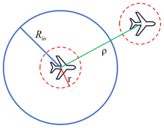
Figure 12.
Schematic of collision avoidance between UAVs.
In Figure 12, is the farthest distance from the geometric center of the UAV to its edge, is the radius of collision avoidance, and is the distance between UAVs. However, the traditional repulsive force model Equation (16) does not consider the size of the UAV and therefore cannot be directly used for collision avoidance between UAVs; at the same time, to make the collision avoidance trajectory smoother, we selected the cotangent function as the potential field function to improve the repulsive force potential field model. The improved repulsive force potential field model is established using the following equation:
The repulsion between UAVs can be expressed as follows:
The repulsive potential field model of (20) fully takes into account the size of the UAV itself and the optimization of the potential field function; however, there is also a local oscillation defect of the repulsive force direction being colocated with the velocity direction, as shown in Figure 13.
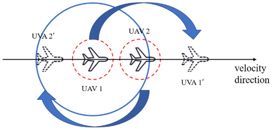
Figure 13.
Schematic of localized oscillations for collision avoidance between UAVs.
In Figure 13, the velocity direction of UAV 1 arriving at the desired position of 1’ is colinear with the direction of the repulsive force of UAV 2 on UAV 1, so it keeps oscillating back and forth at the current position and is unable to form a complete formation. To avoid this situation, in this study, the repulsive force direction was changed by changing the direction of the repulsive force to make it fall outside the local oscillation point. The changed direction of the repulsive force is shown in Figure 14.
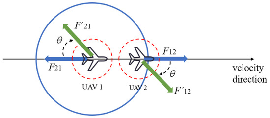
Figure 14.
Schematic of improved repulsions between UAVs.
In Figure 14, the repulsive force at the point of localized oscillation is reduced by an angle to bring it out of the colinear state with the velocity direction to avoid localized oscillation. The repulsive force model after incorporating the deflection angle improvement can be expressed as follows:
In Equation (22), are the repulsive forces between UAVs in the directions, is the azimuthal angle between the UAVs, is the repulsive force change angle, and is the heading angle; is a sign function used to determine whether the UAVs need to change the direction of the repulsive force.
4.2. Simulation Results
4.2.1. Simulation Verification of the IAPF Algorithm
First, the simulation comparison of the IAPF algorithm for a single UAV was carried out to verify the effectiveness of the improved algorithm. The parameters required for simulation are shown in Table 4, and the simulation results are shown in Figure 15 and Figure 16.

Table 4.
Simulation parameter settings.
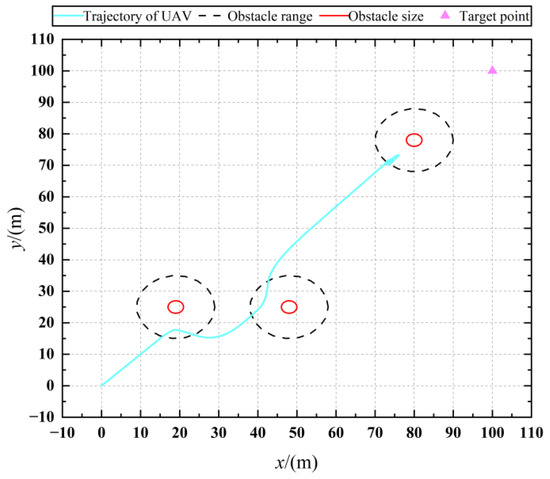
Figure 15.
Trajectory with obstacle avoidance based on APF.
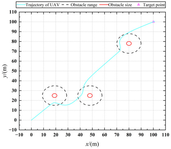
Figure 16.
Trajectory with obstacle avoidance based on IAPF.
Figure 15 shows the UAV’s trajectory of obstacle avoidance under the APF method, and it can be seen that the UAV falls into a local oscillation point when avoiding the third obstacle and cannot fly toward the target point. Figure 16 shows the obstacle avoidance trajectory of the UAV under the IAPF method, and it can be seen that, after offsetting the force at a small angle, the UAV can successfully avoid the third obstacle and reach the target point, which solves the problem of the local oscillating point.
4.2.2. Static Obstacle Avoidance Simulation
In the simulation, the static obstacles of size 5 were set up, the UAV obstacle avoidance range was 60 , and the desired motion state of the UAV was . The initial states of the UAV are shown in Table 5, and the obstacle information is shown in Table 6.

Table 5.
Initial states of the UAV.

Table 6.
Static obstacle information.
The simulation results by combining the APF algorithm (19) and the optimized consensus control algorithm (11) are shown in Figure 17, Figure 18 and Figure 19.
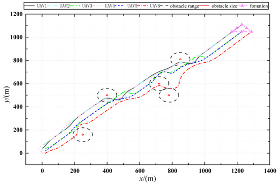
Figure 17.
Trajectory of UAVs with obstacle avoidance.
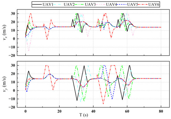
Figure 18.
Velocity of UAVs with obstacle avoidance.
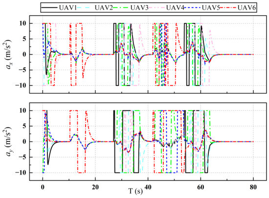
Figure 19.
Acceleration of UAVs with obstacle avoidance.
Figure 17 shows the flight trajectory of the UAV when avoiding obstacles, and the simulation results show the effectiveness of the obstacle avoidance algorithm. Figure 18 and Figure 19 show the change in the velocity and acceleration of the UAV with obstacle avoidance function, respectively. Compared with Figure 4 and Figure 5 in the simulation results of Section 3, the change in velocity is more drastic because of the need to avoid obstacles, but after avoiding obstacles, it also converges to the desired velocity, which demonstrates the validity of the consensus control algorithm. Figure 20 shows the variation in distances between UAVs during obstacle avoidance, and the results show that, under the control of the collision avoidance algorithm, all the distances between UAVs are greater than the minimum distance, thus avoiding collision between UAVs.
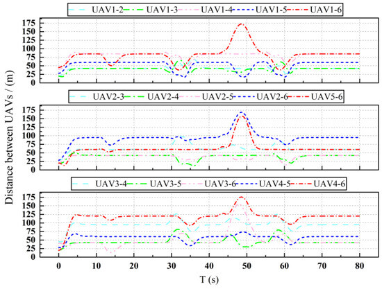
Figure 20.
Distance between UAVs.
4.2.3. Dynamic Obstacle Avoidance Simulation
In this part of the simulation, two groups of dynamic obstacles with different movement velocities were set up, and the number of obstacles in each group was three. Their related information is shown in Table 7. The rest of the simulation parameters are consistent with Section 4.2.1, and the simulation results are shown in Figure 21, Figure 22 and Figure 23.

Table 7.
Dynamic obstacle information.
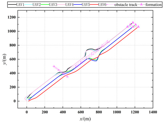
Figure 21.
Trajectory of UAVs with dynamic obstacle avoidance.
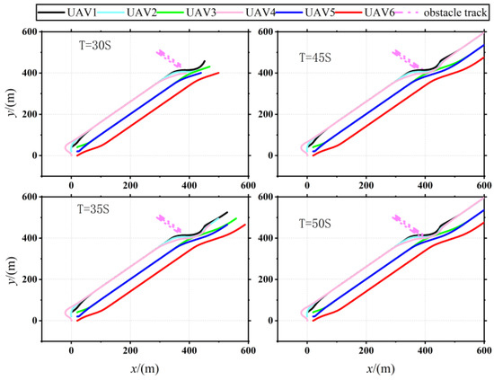
Figure 22.
Diagram of dynamic obstacle avoidance.
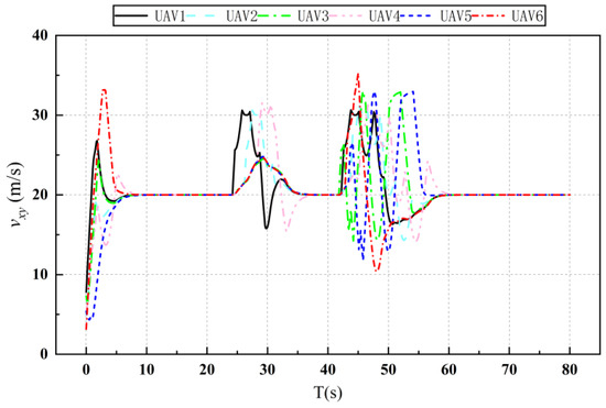
Figure 23.
Total velocity of UAVs with dynamic obstacle avoidance.
Figure 21 and Figure 22 depict the trajectory of a UAV as it navigates around dynamic obstacles. Figure 21 demonstrates that the UAV successfully forms the desired formation after completing the obstacle avoidance process. Figure 22 illustrates the UAVs’ avoidance maneuvers at four distinct time points, highlighting that the designed coherent formation and the improved APF method effectively prevent collisions with dynamic obstacles. Figure 23 displays the variation in the total velocity of the UAVs within the formation. It shows that the velocity of each UAV fluctuates within the predefined constraints. Notably, at two specific times—23 s and 42 s—obstacle interactions necessitate velocity adjustments. Following these adjustments, the UAVs successfully regain velocity consistency after completing the obstacle and collision avoidance maneuvers. These results affirm that the designed consensus formation control algorithm enables the UAVs to achieve and maintain the specified desired flight velocity under dynamic conditions.
5. Conclusions
In this paper, we present a novel obstacle avoidance control method for multi-UAV formation by integrating the APF method with consensus control. This approach allows multi-UAVs to achieve specified flight velocities and desired formation while enhancing the formation’s convergence velocity through optimal control and the PSO algorithm. To address the issue of local optimal commonly associated with traditional APF methods, we increased the deflection angle of the collinear force. Additionally, an optimization term was incorporated to adjust the distance between UAVs and obstacles, effectively resolving the issue of UAV target unreachability. By leveraging the principles of APF, we also enhanced the collision avoidance capabilities among UAVs. Simulation results confirm the effectiveness of the proposed method, demonstrating its practical utility in dynamic and complex environments.
The principal contributions of this study are summarized as follows:
- (1)
- The designed optimal consensus algorithm, enhanced by PSO, enables multi-UAV formation to achieve the desired flight state, significantly improving the performance of formation convergence in comparison to the basic algorithm.
- (2)
- The implementation of the improved APF method, which introduces a small angular offset, resolves the issue of local optimum that typically hampers obstacle avoidance capabilities in UAVs.
- (3)
- Drawing on the principles of the APF method, a new collision avoidance strategy has been developed to prevent collision among UAVs during flight.
However, the research method and simulations discussed in this paper do not account for the potential impacts of communication interference and topology switching. Future research should thus explore robust anti-interference cooperative control in environments with communication disruptions and assess formation stability in scenarios involving topology changes.
Author Contributions
Conceptualization, validation, methodology, P.Z.; methodology, writing—original draft preparation, Y.H.; writing—original draft preparation, Z.W.; writing—review and editing, Q.L. and S.L.; funding acquisition, P.Z. All authors have read and agreed to the published version of the manuscript.
Funding
This research was funded in part by the Shanxi Provincial Fundamental Research Program Grant (Award Number 202103021224187).
Data Availability Statement
The data supporting the conclusions of this article will be made available by the authors upon request.
Acknowledgments
The authors would like to thank all coordinators and supervisors involved and the anonymous reviewers for their detailed comments that helped to improve the quality of this article.
Conflicts of Interest
The authors declare no conflicts of interest.
References
- Ouyang, Q.; Cong, Y.; Wang, Z. Formation Control of Unmanned Aerial Vehicle Swarms: A Comprehensive Review. Asian J. Control 2023, 25, 570–593. [Google Scholar] [CrossRef]
- He, L.; Bai, P.; Liang, X.; Zhang, J.; Wang, W. Feedback formation control of UAV swarm with multiple implicit leaders. Aerosp. Sci. Technol. 2018, 72, 327–334. [Google Scholar] [CrossRef]
- Xue, K.; Wu, T. Distributed Consensus of USVs under Heterogeneous UAV-USV Multi-Agent Systems Cooperative Control Scheme. J. Mar. Sci. Eng. 2021, 9, 1314. [Google Scholar] [CrossRef]
- Zhen, Z.; Tao, G.; Xu, Y.; Song, G. Multivariable adaptive control based consensus flight control system for UAVs formation. Aerosp. Sci. Technol. 2019, 93, 105336. [Google Scholar] [CrossRef]
- Fu, X.; Pan, J.; Wang, H.; Gao, X. A formation maintenance and reconstruction method of UAV swarm based on distributed control. Aerosp. Sci. Technol. 2020, 104, 105981. [Google Scholar] [CrossRef]
- Tao, C.; Zhang, R.; Song, Z.; Wang, B.; Jin, Y. Multi-UAV Formation Control in Complex Conditions Based on Improved Consistency Algorithm. Drones 2023, 7, 185. [Google Scholar] [CrossRef]
- Yue, J.; Qin, K.; Shi, M.; Jiang, B.; Li, W.; Shi, L. Event-Trigger-Based Finite-Time Privacy-Preserving Formation Control for Multi-UAV System. Drones 2023, 7, 235. [Google Scholar] [CrossRef]
- Gu, X.; Chen, G.; Sun, Z.; Sun, Y. Continuous Coverage Control of UAVs Based on Cluster Reconfiguration in the Context of Counterattack. IEEE Access 2023, 11, 85303–85314. [Google Scholar] [CrossRef]
- Ahmed, N.; Pawase, C.; Chang, K. Distributed 3-D Path Planning for Multi-UAVs with Full Area Surveillance Based on Particle Swarm Optimization. Appl. Sci. 2021, 11, 3417. [Google Scholar] [CrossRef]
- Wei, X.; Xu, J. Distributed path planning of unmanned aerial vehicle communication chain based on dual decomposition. Wirel. Commun. Mob. Comput. 2021, 2021, 6661926. [Google Scholar] [CrossRef]
- Haghighi, H.; Asadi, D.; Delahaye, D. Multi-objective cooperated path planning of multiple unmanned aerial vehicles based on revisit time. J. Aerosp. Inf. Syst. 2021, 18, 919–932. [Google Scholar] [CrossRef]
- Wang, N.; Dai, J.; Ying, J. Research on Consensus of UAV Formation Trajectory Planning Based on Improved Potential Field. In Proceedings of the 2021 40th Chinese Control Conference (CCC), Shanghai, China, 26–28 July 2021; pp. 99–104. [Google Scholar]
- Cheng, Z.; Zhao, L.; Shi, Z. Decentralized Multi-UAV Path Planning Based on Two-Layer Coordinative Framework for Formation Rendezvous. IEEE Access 2022, 10, 45695–45708. [Google Scholar] [CrossRef]
- Wang, Y.; Yue, Y.; Shan, M.; He, L.; Wang, D. Formation reconstruction and trajectory replanning for multi-UAV patrol. IEEE/ASME Trans. Mechatron 2021, 26, 719–729. [Google Scholar] [CrossRef]
- Yang, Y.; Xiong, X.; Yan, Y. UAV Formation Trajectory Planning Algorithms: A Review. Drones 2023, 7, 62. [Google Scholar] [CrossRef]
- Fang, Y.; Yao, Y.; Zhu, F.; Chen, K. Piecewise-potential-field-based path planning method for fixed-wing UAV formation. Sci. Rep. 2023, 13, 2234. [Google Scholar] [CrossRef] [PubMed]
- Huang, Y.; Tang, J.; Lao, S. UAV group formation collision avoidance method based on second-order consensus algorithm and improved artificial potential field. Symmetry 2019, 11, 1162. [Google Scholar] [CrossRef]
- Wang, N.; Dai, J.; Ying, J. UAV formation obstacle avoidance control algorithm based on improved artificial potential field and consensus. Int. J. Aeronaut. Space Sci. 2021, 22, 1413–1427. [Google Scholar] [CrossRef]
- Wu, Y.; Gou, J.; Hu, X.; Huang, Y. A new consensus theory-based method for formation control and obstacle avoidance of UAVs. Aerosp. Sci. Technol. 2020, 107, 106332. [Google Scholar] [CrossRef]
- Wu, Y.; Xu, S.; Dai, W.; Lin, L. Heuristic position allocation methods for forming multiple UAV formations. Eng. Appl. Artif. Intell. 2023, 118, 105654. [Google Scholar] [CrossRef]
- Zhang, J.; Yan, J.; Zhang, P.; Kong, X. Collision Avoidance in Fixed-wing UAV Formation Flight Based on a Consensus Control Algorithm. IEEE Access 2018, 6, 43672–43682. [Google Scholar] [CrossRef]
- Liu, H.; Meng, Q.; Peng, F.; Lewis, F. Heterogeneous formation control of multiple UAVs with limited-input leader via reinforcement learning. Neurocomputing 2020, 412, 63–71. [Google Scholar] [CrossRef]
- Yang, Y.; Yang, H.; Liu, F.; Liu, L. Optimal control of distributed multiagent systems with finite-time group flocking. Int. J. Intell. Syst. 2020, 35, 1416–1432. [Google Scholar] [CrossRef]
- Yang, X.; Wang, W.; Huang, P. Distributed optimal consensus with obstacle avoidance algorithm of mixed-order UAVs–USVs–UUVs systems. ISA Trans. 2020, 107, 270–286. [Google Scholar] [CrossRef] [PubMed]
- Bai, T.; Wang, D.; Masood, R. Formation control of quad-rotor UAV via PIO. Sci. China Technol. Sci. 2022, 65, 432–439. [Google Scholar] [CrossRef]
- Zhu, L.; Ma, C.; Li, J.; Lu, Y.; Yang, Q. Connectivity-Maintenance UAV Formation Control in Complex Environment. Drones 2023, 7, 229. [Google Scholar] [CrossRef]
Disclaimer/Publisher’s Note: The statements, opinions and data contained in all publications are solely those of the individual author(s) and contributor(s) and not of MDPI and/or the editor(s). MDPI and/or the editor(s) disclaim responsibility for any injury to people or property resulting from any ideas, methods, instructions or products referred to in the content. |
© 2024 by the authors. Licensee MDPI, Basel, Switzerland. This article is an open access article distributed under the terms and conditions of the Creative Commons Attribution (CC BY) license (https://creativecommons.org/licenses/by/4.0/).