Article

A Framework of Grasp Detection and Operation for Quadruped Robot with a Manipulator

1
Center for Robotics, School of Control Science and Engineering, Shandong University, Jinan 250061, China
2
Engineering Research Center of Intelligent Unmanned System, Ministry of Education, Jinan 250061, China
3
School of Electrical Engineering, University of Jinan, Jinan 250022, China
*
Author to whom correspondence should be addressed.
Drones 2024, 8(5), 208; https://doi.org/10.3390/drones8050208
Submission received: 11 April 2024 / Revised: 13 May 2024 / Accepted: 15 May 2024 / Published: 19 May 2024
(This article belongs to the Special Issue Advanced Unmanned System Control and Data Processing)

Abstract

:
Quadruped robots equipped with manipulators need fast and precise grasping and detection algorithms for the transportation of disaster relief supplies. To address this, we developed a framework for these robots, comprising a Grasp Detection Controller (GDC), a Joint Trajectory Planner (JTP), a Leg Joint Controller (LJC), and a Manipulator Joint Controller (MJC). In the GDC, we proposed a lightweight grasp detection CNN based on DenseBlock called DES-LGCNN, which reduced algorithm complexity while maintaining accuracy by incorporating UP and DOWN modules with DenseBlock. For JTP, we optimized the model based on quadruped robot kinematics to enhance wrist camera visibility in dynamic environments. We integrated the network and model into our homemade robot control system and verified our framework through multiple experiments. First, we evaluated the accuracy of the grasp detection algorithm using the Cornell and Jacquard datasets. On the Jacquard dataset, we achieved a detection accuracy of 92.49% for grasp points within 6 ms. Second, we verified its visibility through simulation. Finally, we conducted dynamic scene experiments which consisted of a dynamic target scenario (DTS), a dynamic base scenario (DBS), and a dynamic target and base scenario (DTBS) using an SDU-150 physical robot. In all three scenarios, the object was successfully grasped. The results demonstrate the effectiveness of our framework in managing dynamic environments throughout task execution.

1. Introduction

Quadruped robots with manipulators combine the motion performance of quadruped robots and the operational capability of manipulators [1,2,3,4], providing innovative solutions for the transportation of supplies to rescue efforts in the environment after a disaster [5,6,7,8], as shown in Figure 1. In these scenarios, the limited payload capacity and dynamic environment place significant demands on the grasping ability of the mounted manipulator.
When transporting supplies after a disaster, robots need to move over rugged terrain. In order to ensure stability during movement, the robot’s own load needs to be minimized, so it cannot be equipped with high-performance industrial computers which are usually large and heavy. In this scenario, the location of the supplies may be outside the operating space of the manipulator, and the robot needs to adjust its base posture to grasp the target. In addition, adverse weather conditions such as aftershocks, strong winds, etc., may also cause the supplies to move. Therefore, the grasping detection algorithm used in these robots must be highly precise, fast, and have low algorithmic complexity. The development of deep learning has made meeting these requirements possible [9]. Researchers have conventionally relied on manually designing geometric features for grasping detection algorithms, resulting in low detection accuracy and difficulty in dealing with unknown objects [10,11,12,13]. However, recent advances in deep learning algorithms have allowed the use of sliding window models and common network structures [14,15,16,17] such as ResNet-50 [18] to extract high-quality grasping features, resulting in improved detection accuracy. Despite these improvements, some methods still suffer from resolution loss due to the scene and produce dense predictions depending on the stride of the sliding window, estimated aspect ratio, and angle of the box [10]. To address this issue, pixel-level networks have been developed. Zeng et al. constructed a robotic pick-and-place system based on the ResNet-101 network. The system takes a 640 × 480 RGBD image as input and generates a densely labeled pixel-wise map of the same resolution [19]. However, the large structure of the network limits real-time detection. To address this issue, Morrison et al. developed lightweight grasping detection networks, GG-CNN and GG-CNN2, at the expense of sacrificing detection accuracy [20]. Therefore, it is important to balance detection accuracy while improving the speed of the grasp detection algorithm.
In addition, the aforementioned deep learning-based grasping detection methods typically rely on vision; therefore, it is important to maintain the target object in the FOV to ensure the grasping detection methods have effective inputs [21]. One challenge faced by quadruped robots with manipulators in outdoor environments is the limited field of view (FOV) of the wrist cameras used for grasping detection, which means objects can leave the FOV as the manipulator moves. The ability of a camera to maintain an object in its FOV during the movement of the manipulator is called visibility. Although equipping robots with an unmanned aerial vehicle to extend the FOV is a commonly used solution, it is expensive [22]. To improve the visibility of the target object during the motion of the manipulator, Chen et al. considered time delay factors in trajectory planning and tracking [23,24,25]. D.-H. Park et al. proposed a method called position-based visual servoing that considers both the visual and physical constraints of the manipulator to compute trajectories that converge to a desired pose [26]. However, this method has not been validated in dynamic environments. T. Shen et al. improved the visibility of a manipulator using manual teaching methods; however, their approach lacks real-time performance and cannot be applied to dynamic scenes [27]. Recent research has explored the use of reinforcement learning to adaptively adjust the motion poses of the manipulator to ensure that the target object remains in view [28]. However, these methods require extensive pretraining and powerful computational resources. To sum up, it is very crucial to develop a path-planning algorithm that does not require additional sensors or devices and considers target visibility while achieving high real-time performance.
To meet the requirements of grasping and detection algorithms for legged robots equipped with manipulators and to enhance the the wrist camera’s visibility of target objects during operations, our contributions are as follows:
(1)
We propose a lightweight grasping convolutional neural network (CNN) based on DenseBlock (DES-LGCNN) to perform pixel-wise detection. Based on two self-made modules (UP and DOWN modules), this algorithm is capable of balancing accuracy and speed during grasp detection.
(2)
We develop a high-visibility motion planning algorithm for manipulators that can ensure the visibility of objects during motion in real time without adding other sensors.
(3)
We integrate the proposed grasping detection algorithm and trajectory optimization model into the control system of our independently developed quadruped robot with a manipulator, which can be used in various environments.
This paper is structured as follows. Some preliminary concepts are described in Section 2. We present the architecture of the framework in Section 3.1 and present the improved methodology in detail in Section 3.2 and Section 3.3. The experiments and results are given in Section 4. Finally, we conclude the study in Section 5.

2. Preliminaries

The joint angles and link numbers of the quadrupedal robot equipped with a manipulator are defined in Figure 2. Due to the robot’s four legs all having the same structure, only the left front leg is labeled in Figure 2. Different numbered coordinate systems are named { O i } , where i represents the coordinate system number. { O c } represents the camera coordinate system. d, l, and  α represent the lengths of the link.
To describe the different joint angles of the robot, we define a symbol θ k , where ∗ represents the number of θ , ranging from 0 to 17, including the angles of the manipulator, torso, and legs; k represents time; and ⊗ represents the attribute, such as min, max, or reference.

3. Methodology

In order to improve the speed and accuracy of grasping detection and the adaptability to dynamic environments when the quadrupedal robot equipped with a manipulator performs the environmental task of transporting materials after disaster, three aspects of grasp detection and operation framework, grasp detection algorithm and robot motion planning algorithm are studied in this paper.

3.1. Architecture of the Framework

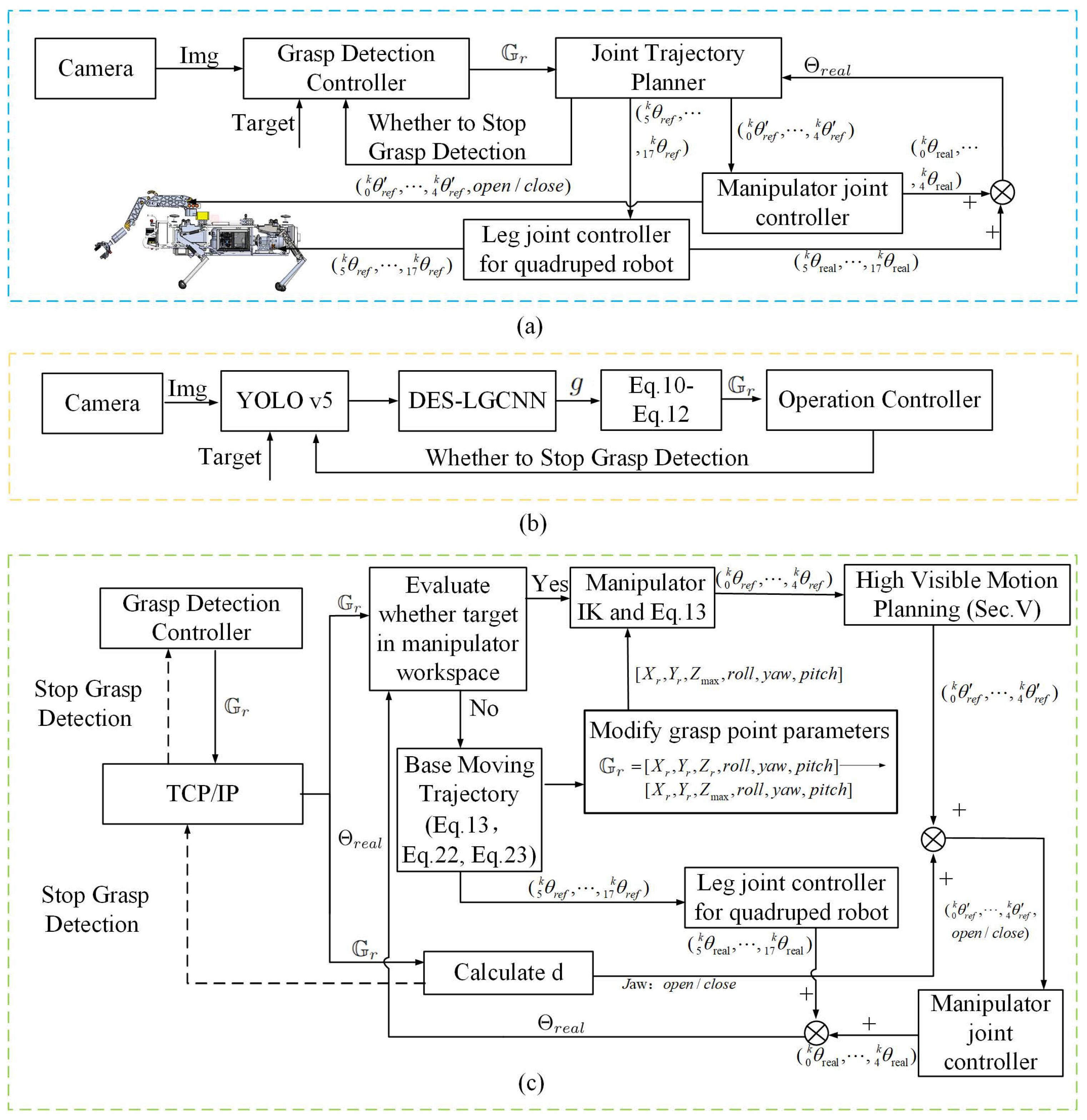
The object detection and grasping framework (Figure 3a) consists of three independent controllers: a Grasp Detection Controller (GDC) (Figure 3b), a Joint Trajectory Planner (JTP) (Figure 3c), a Leg Joint Controller for the quadruped robot, and a Manipulator Joint Controller. To achieve precise grasp detection and effective grasping of the target object, we focused on the design of the GDC (Section 3.2) and JTP (Section 3.3). The input of the entire framework is four-dimensional images and the target type. Communication between different controllers is facilitated using the TCP/IP protocol.
The GDC is mainly responsible for grasp detection, as shown in Figure 3b. The YOLO v5 algorithm is applied to obtain the position of the target object in {I}. Subsequently, the image containing the object information is fed into a lightweight grasping CNN based on DenseBlock (DES-LGCNN), which is developed to generate the grasping point g in {I}. Next, g is transformed into G r using the pinhole model for further analysis using the OC. G r denotes a six-dimensional representation G r = [ X r , Y r , Z r , r o l l , y a w , p i t c h ] . The details of the DES-LGCNN algorithm and the method used to calculate the posture of the End-Effector (EE) will be explained in Section 3.2. We use the OC to obtain the joint angle of the robot at any given time and send it to the leg joint controller for the quadruped robot and the manipulator joint controller (Figure 3c). In the first step in the JTP, the motion planner receives G r using the TCP/IP communication protocol. Afterward, the trajectory planning task is divided into the trajectory planning task of the manipulator and the trajectory planning task of the base based on inverse kinematics (IK) and Equation (15). If the target object is not within the manipulator’s workspace, we need to move the base to expand the working space of the manipulator; otherwise, the base remains stationary. Additionally, to ensure that the target object is within the camera’s FOV, we also need to optimize the path using the proposed high-visibility motion planning algorithm (Section 3.3). Based on the above methods, we derive the reference joint angle values for the base and manipulator joint spaces. These joint angle values are sent to the quadruped robot’s leg joint controller and the manipulator’s joint controller, respectively. The two controllers utilize a PID algorithm. The two controllers execute tasks simultaneously and send real joint angles values Θ r e a l to the JTP while moving.

3.2. Lightweight Grasping Convolutional Neural Network Based on DenseBlock

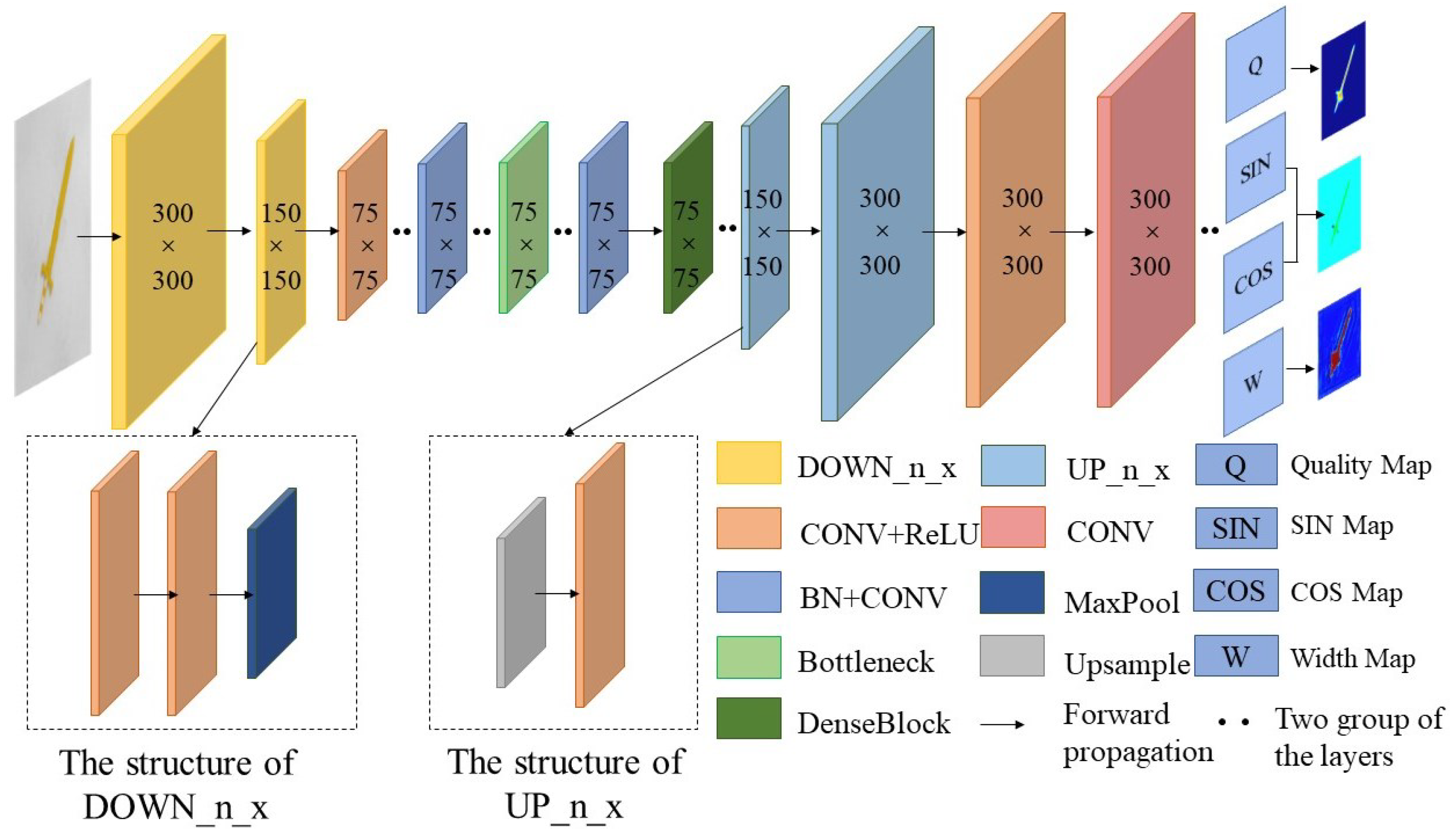
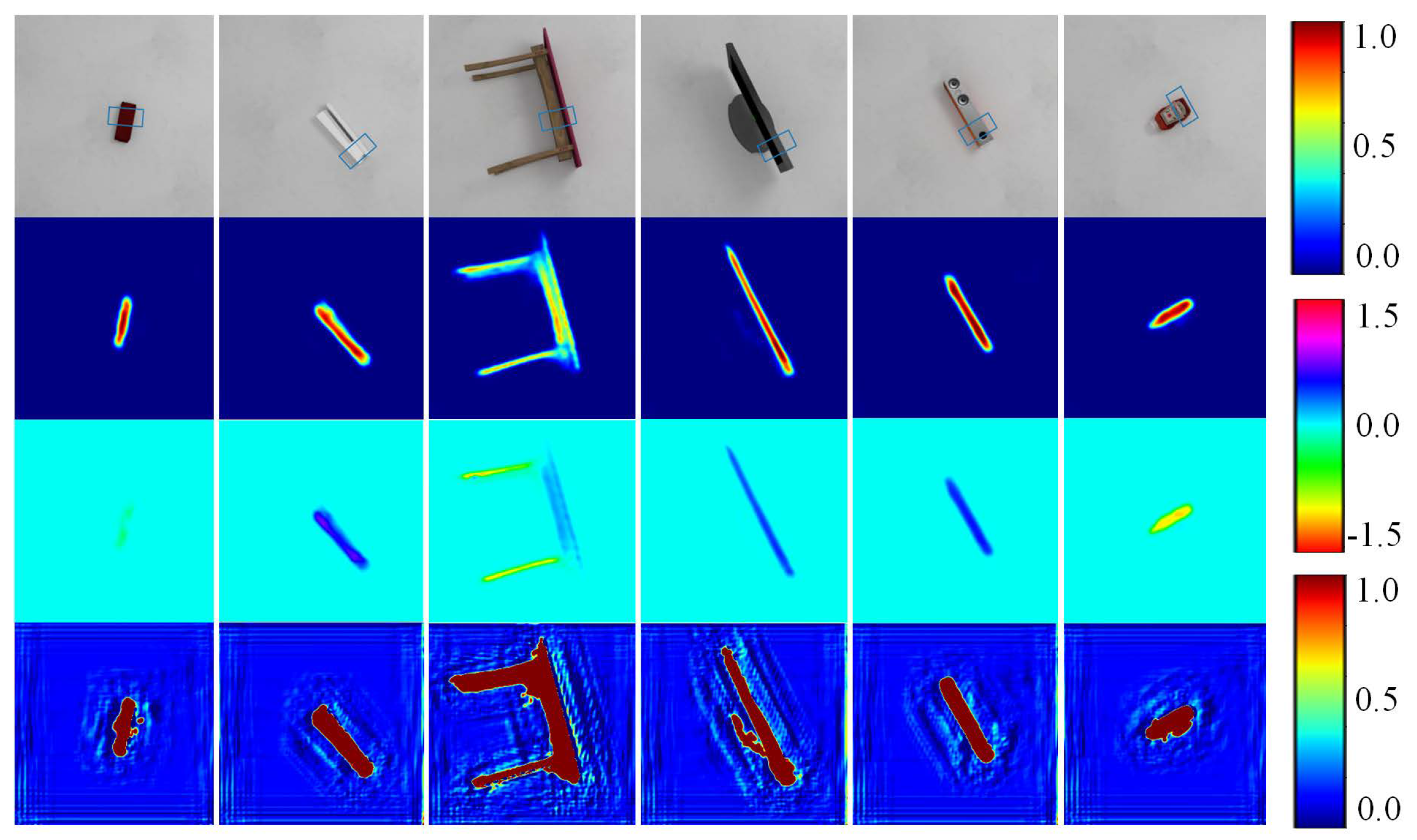
This study introduces DES-LGCNN, a pixel-level neural network (see Figure 4) designed to accurately detect grasp points by analyzing the probability of each pixel in the input image being a grasp point. The network is inspired by GG-CNN, with the input being an image of the target object and the outputs being a grasp quality map (GQM), a grasp angle cosine map (GACM), a grasp angle sine map (GASM), and a grasp width map (GWM) [20]. Three input image modes are available: depth image (D), color image (RGB), and depth image + color image (RGBD). The output image size is consistent with that of the input image. To reduce the number of network parameters and computational complexity, we replaced the deconvolutional layer with our designed UP module, each consisting of an upsampling layer and a convolutional layer. The specific design ideas are described as follows.
In conventional pixel-level neural networks, deconvolution is commonly used to restore the size of the feature map obtained after feature extraction to the size of the input image. The upsampling layer has the same ability as the convolutional layer. We define the height × width × channels of the input for each layer of DES-LGCNN as C in × C in × W in , the output as C out × C out × W out , and the kernel as k × k . Without bias, the computational complexity of deconvolution is as follows:
C out × k 2 × C in 2 × W in
The computational complexity for upsampling using the nearest neighbor algorithm is as follows:
C out 2 C in 2
Let C o u t = C i n × n , where n is increased to the power of two. Equations (1) and (2) are as follows:
C out × k 2 × C in × W in C out 2 C out 2 / n 2 = C out 2 n 2 k 2 × H in × W in × n n 2 + 1
Typically, k 2 × H in × W in × n n 2 1 , making the use of an upsampling layer an effective way to reduce network computation. However, upsampling can result in the loss of information between intervals. We assume that the information about each pixel is related to the surrounding pixels. We added a convolutional layer after the upsampling layer to supplement the missing information. The value of each pixel p c in the new feature map generated by the convolutional layer can be calculated as follows:
p c ( μ i , v j ) = μ = 1 k v = 1 k w u , v p u ( μ i + u 1 , v j + v 1 )
where ( μ i , v j ) represents the position of the pixel in the feature map, and  p u denotes the pixel of the feature map generated by the upsampling layer. w u , v denotes the weight of the kernel at position ( μ , v ) . This reflects the relationship between the current pixel of the new feature map and the surrounding pixels of the pixel in the same position as the old feature map, which can be used to reconstruct lost information. The computation of the bias-free convolutional layer is as follows:
C out 2 × k 2 × C in × W out
Equation (1)/Equation (5) are calculated as follows:
C in × W in C out × W out
The design principle of Equation (6) < 1 can effectively reduce computation. Based on this principle, we designed the Up_n_x layer shown in Figure 4, where x represents the number of channels after the feature map passes through the module, and n indicates that the output feature map is 1 / n × 1 / n of the original. To correspond with the UP module, we designed the DOWN module, which consists of two convolutional layers and a max pooling layer to reduce the feature map size and computation. This module is located in the feature extraction part of the network, specifically the yellow part in front of the Down_n_x network. Here, n indicates that the output feature map is 1 / n × 1 / n of the original. In addition, to avoid the gradient explosion problem that may occur during the forward propagation of the network, we included dense modules in the middle of the network, as shown in the dark green part of Figure 4.
After evaluating different loss functions, we chose the mean squared error (MSE) as the final loss function [20]:
argmin M S E ( G i , G ^ i )
where G i denotes the network-generated grasp feature maps and  G ^ i denotes the ground truth in the i-th training.
After passing through the DES-LGCNN network, we need to convert the output GQM, GASM, GACM, and GWM into values that can be parsed using the OC. The position of the grasp point ( μ g , v g ) and the grasping angle θ g of the grasp point in the image coordinate system are calculated as follows:
μ g , v g = Find ( max ( Q M ( μ , v ) ) )
θ g = 1 2 arctan sin 2 A S M μ g , v g sin 2 A C M μ g , v g
On the basis of Equations (8) and (9), the grasping representation in the image coordinate system can be obtained. We use the five-dimensional model developed by [14] to represent a grasp point g as follows:
g = μ g , v g , θ g , h , w
where h and w represent the height and width of the jaw, respectively. After g is obtained, the pinhole model is used to transform it from the image coordinate system to obtain the position of p g = ( p g x , p g y , p g z ) in { O c } :
p g z μ g v g 1 = f x 0 μ 0 0 f y v 0 0 0 1 p g x p g y p g z
where f x , f y , μ 0 , and  v 0 represent the camera parameters. In addition, to achieve the grasping task, the position and orientation of the EE should be considered. Let G r = [ X r , Y r , Z r , θ g r , θ g y , θ g p , W ] define a grasp in manipulator base coordinates systems; the grasp is determined by the EE’s pose, such as the position of the grasp ( X r , Y r , Z r ) , the roll of the gripper θ g r , the yaw of the gripper θ g y , the pitch of the gripper θ g p , and the gripper width W. Since the gripper we used only has two statuses (open and width), the width is equal to the maximum opening width of the gripper. We can apply the following transformation to convert the grasping representation in { O c } to { O 0 } :
[ X r , Y r , Z r ] T = T 5 0 T c 5 p g
where T c 5 denotes the transformation matrix from { O c } into { O 5 } . T 5 0 denotes the transformation matrix from { O 5 } into { O 0 } . [ X r , Y r , Z r ] represents the position of the grasp point in { O 0 } . θ g r is equal to θ g . θ g p can be set to a fixed value. θ g y can be calculated as
θ g y = a r c t a n 2 ( Y r , X r )
The target state of the manipulator is defined as Θ g o a l = θ g 0 , θ g 1 , , θ g 4 . Based on IK, it can be calculated as
Θ g o a l = I K ( G r )

3.3. High-Visibility Motion Planning Module

High-visibility motion planning refers to the capability of a mobile manipulator to strategically adjust and broaden its FOV by manipulating the pose of its manipulator to ensure that an object is within the FOV. The algorithm of the high-visibility motion planning module is shown in Algorithm 1.
Because quadruped robots are capable of movement, we only need to consider cases in which the G r is outside the manipulator’s workspace in the Z direction. In steps 1–3, when the target object is located within the dexterity space of the manipulator, the target state θ g 0 , θ g 1 , , θ g 4 of the manipulator can be obtained through inverse kinematics. The current state θ real 0 , θ real 1 , , θ real 4 of the manipulator can be obtained using the encoder. On the basis of linear interpolation, the motion path of the manipulator can be obtained. Assuming that the interpolated motion path of the manipulator has α points and the time set for each point is denoted as K, for  k [ 0 , n ] , we obtain
θ ref i k = θ g i θ real i / α × k + θ g i
Based on Equation (15), the motion trajectory of the manipulator can be obtained as ζ = θ ref 0 0 , , θ ref 4 0 , , θ ref 0 n , , θ ref 4 n . When the manipulator travels approximately one-tenth of its trajectory, it undergoes a replanning process. The number of waypoints is fixed each time the replanning process is performed. As the manipulator approaches the target, the angular velocity of each joint decreases to protect both the manipulator and the target object.
Algorithm 1 High-visibility motion planning algorithm
1:
   Θ g o a l I K ( G r )
2:
   ζ E q u a t i o n ( 15 )
3:
  Calculate the distance between the object and the camera d d ( Θ g o a l , ( x c , y c , z c ) )
4:
  while ( k = 0 n ) do
5:
     if  d d m i n  then
6:
        θ  Equation (16)
7:
       if  θ FOV then
8:
           [ θ ref 0 k , , θ ref 4 k ] Equation (22)
9:
          return  [ θ ref 0 k , , θ ref 4 k ]
10:
     else
11:
        return  [ θ ref 0 k , , θ ref 4 k ]
12:
     end if
13:
   else
14:
     if  k = n  then
15:
        close jaw
16:
        break
17:
     else
18:
        return  [ θ ref 0 k , , θ ref 4 k ]
19:
     end if
20:
   end if
21:
end while
In steps 5 and 6, we use a threshold value d m i n to determine whether the EE is close to the object. If the distance between the target object and the EE is too close, only a part of the object will be visible in the FOV, and effective information cannot be extracted. In this case, we proceed directly to steps 14–19. In this section, the manipulator moves according to ζ and closes the jaw when the target position is reached. However, if d d m i n , we use steps 6–12 to determine whether the current trajectory point [ 0 k θ r e f , , n k θ r e f ] should be optimized.
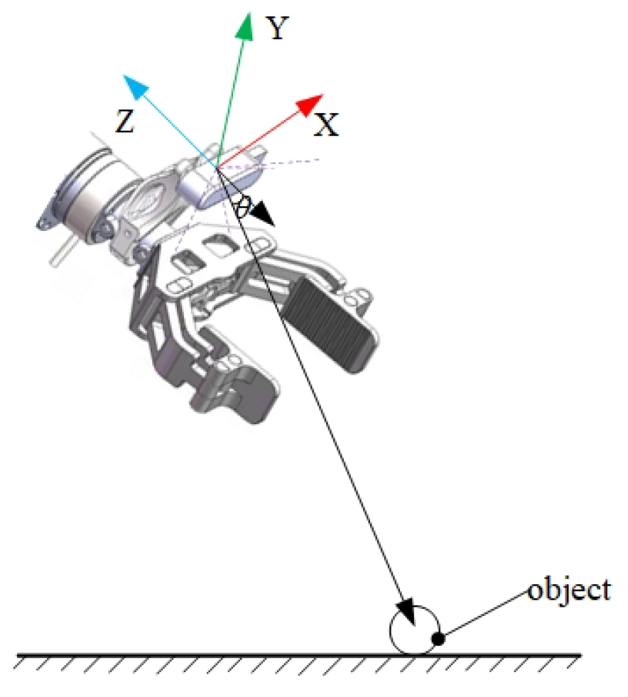
The angle between the vector pointing from the camera’s position to the target object’s center of mass n z c and the line of sight n c o is defined as θ . In { O c } , this angle can be calculated as follows:
θ = arccos n z c ( k ) · n c o ( k ) n z c ( k ) n c o ( k )
where n z c denotes the unit vector (0,0, −1), which is in the opposite direction of the Z-axis of the wrist camera coordinate system. n c o = G r P c , where P c = ( x c ( t ) , y c ( t ) , z c ( t ) ) represents the position of the camera in { O 5 } . A schematic for solving θ is shown in Figure 5.
If the target is not within the FOV, the trajectory must be adjusted (steps 7–9). Otherwise, the trajectory point in ζ is executed directly (steps 10–12). To ensure that the target is as close to the center of the FOV as possible, it is necessary to satisfy
min J n z c ( k ) , n c o ( k ) = 1 n z c ( k ) · n c o ( k ) n z c ( k ) n c o ( k ) s . t . k 0
Typically, to prevent the manipulator from moving back and forth because of the adjustment of the camera view, we add the following constraint:
z c z c ( t )
Based on IK:
x c = a 2 × cos 1 θ cos 2 θ + a 3 cos 1 θ cos θ 2 + 3 θ + d 5 cos θ 1 cos θ 2 + 3 θ + 4 θ
y c = a 2 × sin 1 θ cos 2 θ + a 3 sin 1 θ cos θ 2 + 3 θ + d 5 sin θ 1 cos θ 2 + 3 θ + 4 θ
z c = a 2 × sin 2 θ + d 1 + a 3 × sin θ 2 + 3 θ + d 5 × sin θ 2 + 3 θ + 4 θ
Add Equation (18) to Equation (21) into Equation (17):
min J θ 1 ( k ) , θ 2 ( k ) , θ 3 ( k ) , θ 4 ( k ) s . t . A Θ b min 0 A Θ + b max 0 a 2 × sin θ 2 + d 1 + a 3 × sin θ 2 + θ 3 + d 5 × sin θ 2 + θ 3 + θ 4 z c ( t ) k 0
In Equation (22), A represents the identity matrix. Θ , b min and b max are
Θ = θ 1 , θ 2 , θ 3 , θ 4 T b min = θ min 1 , θ min 2 , θ min 3 , θ min 4 T b max = θ max 1 , θ max 2 , θ max 3 , θ max 4 T
In addition, because 1 n z c ( k ) · n c o ( k ) n z c ( k ) n c o ( k ) 1 , it follows that J [ 0 , 2 ] . Therefore, J must have a minimum value, which can be solved using the Sequential Least Squares Programming (SLSQP) algorithm.
The main idea of calculating the base trajectory is to move the base in such a way that the grasping point is positioned at a specific position in manipulator’s base coordinate system where the object is within the manipulator’s dexterous workspace. When the target is outside the workspace of the manipulator, it is necessary to adjust the distance between the robot’s hip joint and the ground. To reduce the number of variables required to solve the optimization algorithm, the base movement does not expand the FOV of the camera. Take the left front leg as an example. Assuming that the robot’s foot coordinate system is flush with the ground in the vertical direction, we define the robot’s left hip joint in the foot coordinate system as ( X l t ( t ) , Y l t ( t ) , Z l t ( t ) ) . In the vertical direction, the edge of the dexterous workspace of the manipulator is defined as Z max . Δ Z l t ( t ) = Z m a x Z r , with the the reference value Z ref = Z l t ( t ) Δ Z l t ( t ) . According to forward kinematics (FK), the desired angle values for the left front leg are
θ ref 6 = arccos l 1 2 + l 0 X r e f 2 + X l t ( t ) 2 l 2 2 2 l 1 l 0 Z r e f 2 + x 2 arctan X l h ( t ) l 0 + X r e f
θ ref 7 = arccos l 1 2 + l 2 2 l 0 X r e f 2 X l t ( t ) 2 2 l 1 l 2 π
The real angles { θ real 6 , θ real 7 } of the legs are read using the encoder, and the method of solving the trajectory points of the robot’s leg motion is the same as that in Equation (15).

4. Experiments

4.1. Experimental Environment

4.1.1. Network Training and Testing

The personal computer LEGION Y7000 (Lenovo, Beijing, China) is used to train and test the DES-LGCNN algorithm. The hardware system of this personal computer includes an Intel Core I7-10875H CPU (Intel®, Santa Clara, CA, USA), 32 GB RAM, and an NVIDIA GeForce RTX 2060 graphics card (NVIDIA, Santa Clara, CA, USA). The software system mainly includes Ubuntu 18.04, NVIDIA 472.19 graphics card driver, CUDA 11.0, CUDNN V8.0.5, and PyTorch 1.10.0.

4.1.2. Simulation Environment

The simulation platform is constructed on the basis of Webots 2021a. As shown in the left part of Figure 6, we built a five-degree-of-freedom manipulator in the simulation environment. The gripper has two fingers, with the maximum opening and closing reaching 300 mm. In particular, a depth camera for grasping detection is installed on the EE and is placed 15 cm away from the X-axis of the EE. This will ensure that the vision of the camera effectively covers the workspace of the manipulator and avoids its occlusion.

4.1.3. Physical Prototype

The parameters of the self-made hydraulic manipulator are consistent with those of the simulation environment. The object recognition and grasp detection modules are also deployed in LEGION Y7000 with the same hardware as that described in Section 4.1.1. The Compact-RIO 9039 controller (NI, Austin, TX, USA) is used to control the motion of the manipulator. A local area network is constructed between LEGION Y7000 and the Compact-RIO 9039 controller, and the TCP/IP protocol is used for communication. The experimental environment of the manipulator is shown on the right side of Figure 6.
To evaluate the performance of our algorithm on a quadruped robot, we used the SDU-150 quadruped robot as the chassis and equipped it with our own manipulator. The parameters of the robot is shown Table 1. The robot’s base comprises 12 hydraulic servo valves, 12 force sensors, and 12 displacement sensors. Among these, the hydraulic servo valves control the movement of the robot’s legs, the displacement sensors obtain actual motion parameters of each joint in the legs, and the force sensors facilitate force control and feedback for each joint. The manipulator consists of one force sensor (mounted at the EE), five hydraulic servo valves, and five encoders. The hydraulic servo valves are responsible for controlling the manipulator’s motion. Force sensors are employed for force control and feedback regarding the manipulator’s load. Encoders are utilized to read the actual joint angles, and via inverse kinematics, the EE position can be determined. All the aforementioned data are output through the SDU-150’s logging module at a frequency of 100 Hz.
The robot’s controller is a self-made servo controller with high shock resistance. The robot and manipulator share the same upper computer, a LEGION Thinkpad, with the manipulator controller. The quadruped robot equipped with a manipulator is shown in the middle of Figure 6. The upper computer communicates with LEGION Y7000 through the TCP/IP protocol. The hardware and software are described in the bottom half of Figure 6.

4.2. Validation of DES-LGCNN

The Cornell and Jacquard datasets are commonly used to evaluate grasp detection algorithms. We selected these two datasets for comparative experiments and used accuracy and speed as evaluation indices. For a fair comparison with other studies, when the intersection-over-union score is greater than 25% and the angle error is less than 30°, the grasp is considered correct.
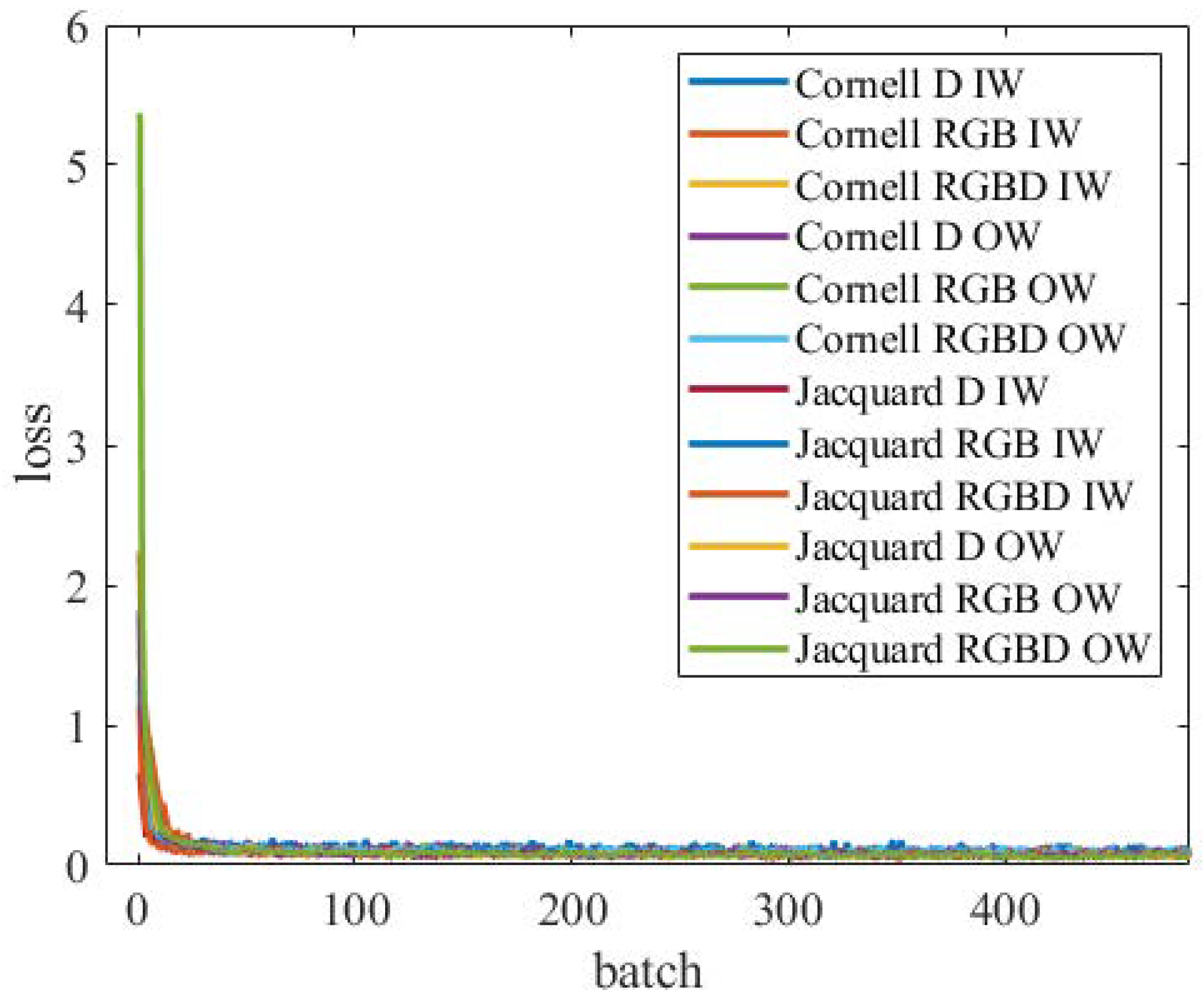
During the training process, we use 80% of each dataset as a training set and the remaining 20% as a test set. The number of epochs is set to 400. The learning rate is set to a gradient descent with step decay. The initial learning rate is 0.01 and decreases by 1 / 10 every 100 epochs. During the training process, we recorded the variations in the loss function under different conditions, primarily involving the two datasets with inputs of D, RGB, and RGBD images. The datasets were classified using two methods, image-wise split (IW) and object-wise split (OW), resulting in six scenarios, as shown in Figure 7. As shown in the figure, in the aforementioned six scenarios, the loss function converges rapidly. After approximately 20 batches, the loss functions in all scenarios converge to values close to 0.
Figure 8 shows part of our experimental results. The results show that our network can effectively detect grasping points. A comparison of the experimental results is shown in Table 2 and Table 3. Table 2 shows the experimental results for the Cornell dataset in terms of grasping accuracy, network size, and calculated speeds of different algorithms. In Table 2, when the input is RGBD images, our network has the highest accuracy and the fastest detection speed. The accuracy is 92.49% for IW and 92.39% for OW, and the detection speed is 6 ms. When RGB images are used for recognition, the IW and OW accuracies of GraspNet are slightly higher than those of our network, but the detection speed is slower. Our network has lower accuracy when only D information is used. In addition, the classification method of the dataset has little influence on accuracy.
Table 3 shows the experimental results for the Jacquard dataset in terms of the accuracy of the different algorithms. Our algorithm achieves the highest accuracy of 92.22% when the input is RGBD images. In contrast to the performance on the Cornell dataset, when the network uses only D information, the accuracy is not significantly lower than when using RGBD information. It is possible that the Jacquard dataset has a larger scale, which can provide the network with more depth information. However, when only RGB information is used, our algorithm performs moderately well.
Table 2 and Table 3 show that the proposed algorithm has high grasp detection accuracy and fast speed, effectively ensuring the real-time performance of grasping detection and providing a basis for the implementation of closed-loop control.

4.3. Simulation Experiment

We optimized our algorithm in the dexterous workspace of the manipulator using the SLSQP algorithm. The results are presented in Figure 9. In this space, we select a point every 2 cm for computation using Equation (22). The FOV of the camera is set to 67°, which is similar to that of the commonly used Realsense D435i camera.
In Figure 9, 39,000 points are sampled within the aforementioned space. Of these, 38,980 points are marked in blue, and only 20 points are marked in red. In Figure 9c,d, note that the red points are primarily at the edges of the dexterous workspace. This suggests that our model may require further refinement to handle situations at the edges of the workspace. In addition, most of the unsolvable cases occur when the gripper is approximately 12 cm away from the target object and the camera is positioned very close to the target object with a limited FOV. In such cases, it is understandable that obtaining an effective solution is difficult because our algorithm does not allow the gripper to move far away from the object in the vertical direction. Overall, these results are promising and indicate that our model is well-suited for various tasks in the dexterous workspace of the manipulator.
To evaluate the real-time performance of our motion control algorithm, we conducted a visibility detection experiment. To verify the visibility of our proposed motion planning algorithm, we compared it with the A*, RRT, and RRT* algorithms in a simulation environment.
We propose a ratio ϑ to measure the ability of the motion planning algorithm to keep an object in the FOV:
ϑ = t i n t
where t represents the total time spent from the first detection to the time the EE grasped the object successfully and t i n represents the time the object was in the FOV during movement. The larger the ϑ , the better the visibility of our motion planning algorithm. Referring to the FOV of commonly used cameras, the FOV of the wrist camera is set to 150°, 120°, 90°, and 60°. Because the trajectory generated by the genetic algorithm is random, we randomly placed the target object in 20 different positions and grasped the object five times in each position using different algorithms when the FOV was fixed. The evaluation indicator is calculated by averaging all ϑ under the same FOV using the same algorithm, as presented in Table 4.
When the FOV is set to 150° and 120°, it is similar to that of a global camera. At this point, all motion planning algorithms can effectively ensure that the detected object is always in the FOV during movement. However, when the FOV is reduced to 90°, the ϑ of the other three algorithms decreases sharply. When the FOV is further reduced, our algorithm loses sight of objects approximately 16.66% of the time; these instances are concentrated at the end of the grasping process. At this time, the object is very close to the gripper, and when the FOV of the wrist camera is small, the gripper is in a blind area of the camera’s vision.

4.4. Dynamic Grasping in Real-World Environments

During post-disaster rescue operations, supplies are often packed in camouflage bags. Therefore, this study conducted experiments on camouflage bags. The dynamic grasping experiment is conducted in three scenarios: a dynamic target scenario (DTS), a dynamic base scenario (DBS), and a dynamic target and base scenario (DTBS). Figure 10 shows the experimental scenarios and the relevant data for DTS, DBS, and DTBS.
To verify the grasping ability of the algorithm in the DTS, an object is placed on a sorting box with wheels so that the object can be moved by dragging the box. The manipulator is placed on a stable platform to ensure that the base of the manipulator does not move. The entire grasping process is depicted in Figure 10a. The object moves within the workspace of the manipulator, and the manipulator tracks the object and grasps it successfully. During the process of grasping, the manipulator is repositioned several times. We selected three representative instances to demonstrate this (Figure 11a). The red line indicates the reference trajectory of the EE, and the blue line indicates the real trajectory. The yellow, purple, and green lines indicate the first, second, and third planning trajectories, respectively. Each planned trajectory effectively reflects the motion of the object. When the object moves, the newly planned trajectory will cover the unreachable part of the original trajectory and finally form the completed reference trajectory. To ensure that there is sufficient effective information in the FOV, when the distance between the EE and the object is less than 20 cm, the grasp detection algorithm stops its process and the planned trajectory does not change. In the early grasping stage, the swing amplitude of the manipulator is significant because the given waypoints are sparse. In the late grasping stage, the reference waypoints are dense; thus, the swing amplitude of the manipulator is effectively reduced. Finally, the manipulator successfully grasps the object. This experiment proves the effectiveness of our algorithm applied to a hydraulic manipulator in a real-world environment.
To evaluate the performance of the algorithm in the DBS, we used a quadruped robot with a manipulator. An object is placed on the ground in front of the robot. Because the workspace of the manipulator is limited, the robot must perform a squatting motion to reach the object. The entire experiment process is depicted in Figure 10b. In this experiment, when the object is beyond the manipulator’s workspace, the mobile base moves to the ground at a speed v h = h / t until the target enters the manipulator’s workspace. Here, h represents the height at which the robot base should descend. t represents the execution time at which the EE moves to the target position. In this process, the manipulator continues to move along the planned trajectory and maintains grasping detection.
Figure 11b indicates the trajectory of the EE. The red curve indicates the real trajectory, and the blue curve indicates the reference trajectory. The second line graph shows the distance between the hip joints and the ground when the robot squats. The blue, yellow, green, and red curves correspond to the lf, rf, lh, and rh of the robot, respectively. The data represent the values of the robot’s hip coordinate system in the upper and lower directions of the ground coordinate system. The robot is powered on from the squatting mode to the initial mode in 0–2.5 s, as shown in Figure 11c. During this period, the four curves tended to first rise and then remain stable. Notably, the robot body starts to descend at 2.5 s and quickly returns to a standing state at 4 s. During the entire grasping process, the object is always in the FOV, and the manipulator finally grasps the object successfully.
Figure 10c illustrates the grasping process in the DTBS. The motion curve of the EE during this period is shown in Figure 11d. As shown in the figure, the EE has a tracking trend for the movement of the object. In the beginning, to enable the EE to move to the location of the object, its trend moves to the right. As the object moves to the left, the EE follows it and moves toward the left. Similar to the experiment shown in Figure 11a, when the distance between the EE and the object is less than 20 cm, the manipulator stops detecting the location of the object. The EE moves toward the object directly according to the planned trajectory without adjusting the initial planned trajectory according to the visibility. Figure 11e shows the distances between the four hips and the ground when the robot squats. Unlike in the DBS, the hip velocities change because of the movement of the object.

5. Conclusions

In our research endeavor, we introduce a pioneering closed-loop grasping strategy tailored for quadruped robots outfitted with manipulators. Central to our approach is the deployment of the DES-LGCNN, a lightweight neural network adept at discerning high-precision grasps while mitigating computational overhead. Impressively, this network boasts a detection time of a mere 6 milliseconds, sustaining an accuracy rate surpassing 92%. Moreover, our innovation extends beyond mere detection; we have devised a trajectory planning algorithm meticulously engineered to ensure sustained visibility of the target object within the camera’s field of view (FOV) throughout manipulator motion. In the experiment, our algorithm reaches the visibility of 83.33% when the FOV of the camera is only 60°, while other algorithms only reach a visibility of 62.65%. This continuous visual feedback loop enriches the control algorithm, empowering it to adapt dynamically to changing scenarios, even in instances where the robot’s torso exhibits non-static behavior.
Notably, the effectiveness of the algorithm is only tested when the robot’s torso moves up and down in our experiments, because the robot needs to have a high-precision positioning ability to realize forward and backward movements. This problem requires the robot to have a strong location ability. In the future, our objective will revolve around seamlessly integrating the manipulator subsystem within the broader robotic framework. Such integration would pave the way for a spectrum of sophisticated functionalities, including remote target recognition and autonomous navigation and operations. In the forthcoming research, we aim to make a highly integrated environmental awareness system, enabling the robot to navigate diverse environments autonomously while executing complex tasks with finesse. Through such advancements, we envision a future where robotic systems exhibit unparalleled versatility and adaptability, revolutionizing industries ranging from rescue to exploration.

Supplementary Materials

The following supporting information can be downloaded at: https://www.mdpi.com/article/10.3390/drones8050208/s1.

Author Contributions

Methodology, J.G.; Software, J.G.; Validation, Q.Z.; Investigation, M.C. and Y.L. (Yueyang Li); Writing—original draft, J.G.; Writing—review and editing, H.Z.; Project administration, Y.L. (Yibin Li); Funding acquisition, H.C. All authors have read and agreed to the published version of the manuscript.

Funding

This work was supported in part by the National Key Research and Development Program of China, Grant No. 2022YFB4701503; in part by the National Natural Science Foundation of China under Grant No. 62073191; in part by the Shandong Provincial Key R&D Program (Major Scientific and Technological Innovation Project) under Grant No. 2019JZZY010441; in part by the Shandong Provincial Natural Science Foundation under Grant No. ZR2022MF296; and in part by the Project of the Shandong Province Higher Educational Youth and Innovation Talent Introduction and Education Program.

Data Availability Statement

Data are contained within the article and Supplementary Materials.

Conflicts of Interest

The authors declare no conflicts of interest.

References

  1. Chen, G.; Hong, L. Research on Environment Perception System of Quadruped Robots Based on LiDAR and Vision. Drones 2023, 7, 329. [Google Scholar] [CrossRef]
  2. Chen, T.; Li, Y.; Rong, X.; Zhang, G.; Chai, H.; Bi, J.; Wang, Q. Design and Control of a Novel Leg-Arm Multiplexing Mobile Operational Hexapod Robot. IEEE Robot. Autom. Lett. 2021, 7, 382–389. [Google Scholar] [CrossRef]
  3. Zhang, G.; Ma, S.; Shen, Y.; Li, Y. A Motion Planning Approach for Nonprehensile Manipulation and Locomotion Tasks of a Legged Robot. IEEE Trans. Robot. 2020, 36, 855–874. [Google Scholar] [CrossRef]
  4. Chen, T.; Sun, X.; Xu, Z.; Li, Y.; Rong, X.; Zhou, L. A trot and flying trot control method for quadruped robot based on optimal foot force distribution. J. Bionic Eng. 2019, 16, 621–632. [Google Scholar] [CrossRef]
  5. Chai, H.; Li, Y.; Song, R.; Zhang, G.; Zhang, Q.; Liu, S.; Hou, J.; Xin, Y.; Yuan, M.; Zhang, G.; et al. A survey of the development of quadruped robots: Joint configuration, dynamic locomotion control method and mobile manipulation approach. Biomim. Intell. Robot. 2022, 2, 100029. [Google Scholar] [CrossRef]
  6. Pang, L.; Cao, Z.; Yu, J.; Guan, P.; Rong, X.; Chai, H. A visual leader-following approach with a TDR framework for quadruped robots. IEEE Trans. Syst. Man. Cybern. Syst. 2019, 51, 2342–2354. [Google Scholar] [CrossRef]
  7. Wang, P.; Zhou, X.; Zhao, Q.; Wu, J.; Zhu, Q. Search-based Kinodynamic Motion Planning for Omnidirectional Quadruped Robots. In Proceedings of the 2021 IEEE/ASME International Conference on Advanced Intelligent Mechatronics (AIM), Virtually, 12–16 July 2021; pp. 823–829. [Google Scholar]
  8. Zhang, Y.; Tian, G.; Shao, X.; Liu, S.; Zhang, M.; Duan, P. Building metric-topological map to efficient object search for mobile robot. IEEE Trans. Ind. Electron. 2021, 69, 7076–7087. [Google Scholar] [CrossRef]
  9. Fu, X.; Wei, G.; Yuan, X.; Liang, Y.; Bo, Y. Efficient YOLOv7-Drone: An Enhanced Object Detection Approach for Drone Aerial Imagery. Drones 2023, 7, 616. [Google Scholar] [CrossRef]
  10. Miller, A.T.; Allen, P.K. Graspit! A versatile simulator for robotic grasping. IEEE Robot. Autom. Mag. 2004, 11, 110–122. [Google Scholar] [CrossRef]
  11. Pelossof, R.; Miller, A.; Allen, P.; Jebara, T. An SVM learning approach to robotic grasping. In Proceedings of the 2004 IEEE International Conference on Robotics and Automation (ICRA), New Orleans, LA, USA, 26 April–1 May 2004; Volume 4, pp. 3512–3518. [Google Scholar]
  12. Saxena, A.; Driemeyer, J.; Ng, A.Y. Robotic grasping of novel objects using vision. Int. J. Robot. Res. 2008, 27, 157–173. [Google Scholar] [CrossRef]
  13. Rusu, R.B.; Bradski, G.; Thibaux, R.; Hsu, J. Fast 3d recognition and pose using the viewpoint feature histogram. In Proceedings of the 2010 IEEE/RSJ International Conference on Intelligent Robots and Systems, Taipei, Taiwan, 18–22 October 2010; pp. 2155–2162. [Google Scholar]
  14. Lenz, I.; Lee, H.; Saxena, A. Deep learning for detecting robotic grasps. Int. J. Robot. Res. 2015, 34, 705–724. [Google Scholar] [CrossRef]
  15. Guo, D.; Sun, F.; Liu, H.; Kong, T.; Fang, B.; Xi, N. A hybrid deep architecture for robotic grasp detection. In Proceedings of the 2017 IEEE International Conference on Robotics and Automation (ICRA), Singapore, 29 May–3 June 2017; pp. 1609–1614. [Google Scholar]
  16. Zhang, H.; Zhou, X.; Lan, X.; Li, J.; Tian, Z.; Zheng, N. A real-time robotic grasping approach with oriented anchor box. IEEE Trans. Syst. Man. Cybern. Syst. 2019, 51, 3014–3025. [Google Scholar] [CrossRef]
  17. Zhou, X.; Lan, X.; Zhang, H.; Tian, Z.; Zhang, Y.; Zheng, N. Fully convolutional grasp detection network with oriented anchor box. In Proceedings of the 2018 IEEE/RSJ International Conference on Intelligent Robots and Systems (IROS), Madrid, Spain, 1–5 October 2018; pp. 7223–7230. [Google Scholar]
  18. Chu, F.J.; Xu, R.; Vela, P.A. Real-world multiobject, multigrasp detection. IEEE Robot. Autom. Lett. 2018, 3, 3355–3362. [Google Scholar] [CrossRef]
  19. Zeng, A.; Song, S.; Yu, K.T.; Donlon, E.; Hogan, F.R.; Bauza, M.; Ma, D.; Taylor, O.; Liu, M.; Romo, E.; et al. Robotic pick-and-place of novel objects in clutter with multi-affordance grasping and cross-domain image matching. Int. J. Robot. Res. 2022, 41, 690–705. [Google Scholar] [CrossRef]
  20. Morrison, D.; Corke, P.; Leitner, J. Closing the loop for robotic grasping: A real-time, generative grasp synthesis approach. arXiv 2018, arXiv:1804.05172. [Google Scholar]
  21. Ma, J.; Chen, P.; Xiong, X.; Zhang, L.; Yu, S.; Zhang, D. Research on Vision-Based Servoing and Trajectory Prediction Strategy for Capturing Illegal Drones. Drones 2024, 8, 127. [Google Scholar] [CrossRef]
  22. Tranzatto, M.; Miki, T.; Dharmadhikari, M.; Bernreiter, L.; Kulkarni, M.; Mascarich, F.; Andersson, O.; Khattak, S.; Hutter, M.; Siegwart, R.; et al. CERBERUS in the DARPA Subterranean Challenge. Sci. Robot. 2022, 7, eabp9742. [Google Scholar] [CrossRef]
  23. Chen, H.; Chen, Y.; Wang, M. Trajectory tracking for underactuated surface vessels with time delays and unknown control directions. IET Control Theory Appl. 2022, 16, 587–599. [Google Scholar] [CrossRef]
  24. Chen, H.; Shen, C.; Huang, J.; Cao, Y. Event-triggered model-free adaptive control for a class of surface vessels with time-delay and external disturbance via state observer. J. Syst. Eng. Electron. 2023, 34, 783–797. [Google Scholar] [CrossRef]
  25. Chen, Y.; Chen, H. Prescribed performance control of underactuated surface vessels’ trajectory using a neural network and integral time-delay sliding mode. Kybernetika 2023, 59, 273–293. [Google Scholar] [CrossRef]
  26. Park, D.H.; Kwon, J.H.; Ha, I.J. Novel position-based visual servoing approach to robust global stability under field-of-view constraint. IEEE Trans. Ind. Electron. 2011, 59, 4735–4752. [Google Scholar] [CrossRef]
  27. Shen, T.; Radmard, S.; Chan, A.; Croft, E.A.; Chesi, G. Optimized vision-based robot motion planning from multiple demonstrations. Auton. Robot. 2018, 42, 1117–1132. [Google Scholar] [CrossRef]
  28. Shi, H.; Sun, G.; Wang, Y.; Hwang, K.S. Adaptive image-based visual servoing with temporary loss of the visual signal. IEEE Trans. Ind. Inform. 2018, 15, 1956–1965. [Google Scholar] [CrossRef]
  29. Redmon, J.; Angelova, A. Real-time grasp detection using convolutional neural networks. In Proceedings of the 2015 IEEE International Conference on Robotics and Automation (ICRA), Seattle, WA, USA, 26–30 May 2015; pp. 1316–1322. [Google Scholar]
  30. Wang, Z.; Li, Z.; Wang, B.; Liu, H. Robot grasp detection using multimodal deep convolutional neural networks. Adv. Mech. Eng. 2016, 8, 1687814016668077. [Google Scholar] [CrossRef]
  31. Asif, U.; Tang, J.; Harrer, S. GraspNet: An Efficient Convolutional Neural Network for Real-time Grasp Detection for Low-powered Devices. In Proceedings of the 2018 International Joint Conference on Artificial Intelligence(IJCAI), Stockholm, Sweden, 13–19 July 2018; Volume 7, pp. 4875–4882. [Google Scholar]
  32. Kumra, S.; Kanan, C. Robotic grasp detection using deep convolutional neural networks. In Proceedings of the 2017 IEEE/RSJ International Conference on Intelligent Robots and Systems (IROS), Vancouver, BC, Canada, 24–28 September 2017; pp. 769–776. [Google Scholar]
  33. Depierre, A.; Dellandréa, E.; Chen, L. Scoring Graspability based on Grasp Regression for Better Grasp Prediction. In Proceedings of the 2021 IEEE International Conference on Robotics and Automation (ICRA), Xi’an, China, 30 May–5 June 2021; pp. 4370–4376. [Google Scholar] [CrossRef]
Figure 1. Legged robots equipped with manipulators combine the flexibility of legged robots and the operation capability of the manipulator. Due to the challenges posed by mobile bases, complex environments, and varied tasks, accurate detection and manipulation of objects requires sophisticated techniques. This study focuses on solving these problems, as indicated in the red section.
Drones 08 00208 g001
Figure 2. D-H model for manipulator and leg of robot. The structure of each leg is identical, and only the front leg is labeled, whereas the indices for the other legs are incremented accordingly.
Drones 08 00208 g002
Figure 3. Developed framework of grasp detection and operation for a quadruped robot with a manipulator. (a) Entire framework of the system. (b) Framework of the GDC. (c) Framework of the JTP.
Drones 08 00208 g003
Figure 4. Architecture of DES-LGCNN. The left and right dashed rectangles represent the architecture of DOWN _ x _ n and UP _ x _ n modules, respectively. In this figure, different colors represent different network structures.
Drones 08 00208 g004
Figure 5. Schematic for solving θ .
Drones 08 00208 g005
Figure 6. Setup for simulation and real-world experiment. This figure describes the simulation environment, the experimental environment in the real world for our five-degree-of-freedom hydraulic manipulator, the SDU-150 quadruped robot equipped with a manipulator, and the hardware and software of the control system.
Drones 08 00208 g006
Figure 7. Change in loss function during training.
Drones 08 00208 g007
Figure 8. Detection result of DES-LGCNN. Columns 1 to 4 represent grasping representation, grasp quality, grasp angle, and grasp width images, respectively. The three bars on the right from top to bottom correspond to the color of the grasp quality feature map, grasp angle feature map, and gripper width feature map, respectively.
Drones 08 00208 g008
Figure 9. Visibility of optimization algorithms in the dexterous space of the manipulator. (a) The X-axes and Y-axes in this figure represent the position of the target object in the base coordinate system of the manipulator, and the Z-axis represents the vertical distance between the EE and the target object. The optimal solution obtained using our model within the FOV of the camera is shown in blue and outside it in red. (bd) The projections of (a) onto different planes. Color intensity indicates the number of unsolvable points at each position.
Drones 08 00208 g009
Figure 10. Three experiment scenarios: (a) DTS, (b) DBS, and (c) DTBS.
Drones 08 00208 g010
Figure 11. Relevant data on grasping in dynamic scenarios. Each line indicates information about the EE and hip joints in a different scenario. The circle represents the start and end of the object’s movements. (a) Trajectory of EE in DTS. (b) Trajectory of EE in DBS. (c) Trajectory of hips in DBS. (d) Trajectory of EE in DTBS. (e) Trajectory of hips in DTBS.
Drones 08 00208 g011
Table 1. The parameters of SDU-150 equipped with a manipulator.
ParametersValue
length1420 mm
width693 mm
height700 mm
weight240 kg
climbing slope25°
obstacle crossing250 mm
max speed1.8 m / s
manipulator load30 kg
Table 2. Comparison of grasp dataset parameters on Cornell dataset.
ApproachIW (%)OW (%)Speed (ms)
SAE [14]73.975.661350
Alxnet, MultiGrasp [29]88.087.176
Two-stage closed-loop [30]85.3-140
GG-CNN [20]73.069.019
GraspNet [31]90.290.624
ResNet-50x2 [32]89.288.9103
ours-RGB90.5989.896
ours-D80.4881.265.5
ours-RGBD92.4992.396
Table 3. Comparison of grasp dataset parameters on Jacquard dataset.
ApproachIW (%)OW (%)Speed (ms)
FCGN(ResNet-50) [17]89.8389.2628
GG-CNN2 [20]848319
New DNN [33]85.74--
ours-RGB8688.646
ours-D91.3991.085.5
ours-RGBD92.2292.356
Table 4. Visibility under different algorithms.
Algorithm150°120°90°60°
A*100%100%70.83%62.65%
RRT100%100%65.07%53.14%
RRT*100%100%59.61%51.71%
Ours100%100%97.15%83.33%
Disclaimer/Publisher’s Note: The statements, opinions and data contained in all publications are solely those of the individual author(s) and contributor(s) and not of MDPI and/or the editor(s). MDPI and/or the editor(s) disclaim responsibility for any injury to people or property resulting from any ideas, methods, instructions or products referred to in the content.