Article

Adaptive Terminal Time and Impact Angle Constraint Cooperative Guidance Strategy for Multiple Vehicles

School of Automation, Northwestern Polytechnical University, Xi’an 710072, China
*
Author to whom correspondence should be addressed.
Drones 2024, 8(4), 134; https://doi.org/10.3390/drones8040134
Submission received: 19 February 2024 / Revised: 20 March 2024 / Accepted: 29 March 2024 / Published: 2 April 2024

Abstract

:
This paper addresses the guidance of various flight vehicles under multiple constraints in three-dimensional space. A cooperative guidance strategy that satisfies both time and angle constraints is designed to reach a moving target. The strategy is organized into two parts: modeling and programming calculations. First, a nonlinear motion model for guidance is established and normalized, including both the vehicle and the target. Later, the arrival method is automatically determined according to the strategy and depending on the type of target. The cooperative terminal time is determined based on an augmented proportional navigation method. An improved model predictive static programming (MPSP) algorithm was designed as a means of adjusting the adaptive terminal time. Then, the algorithm was used to update the control quantity iteratively until the off-target quantity and the angle of constraints were satisfied. The simulation results showed that the strategy could enable multiple flight vehicles at different initial positions to reach the target accurately at the same time and with the ideal impact angle. The strategy boasts a high computational efficiency and is capable of being implemented in real time.

1. Introduction

Impact angle constrained guidance has important application scenarios in a number of fields, especially where the angle at which a vehicle impacts a target needs to be precisely controlled. In the field of unmanned aerial vehicle (UAV) operations, the application of impact angle constrained guidance techniques is mainly focused on improving the accuracy and efficiency of mission execution, while use of multiple UAVs is also playing an increasingly important role in modern society, and civil and scientific research. This mission paradigm, which involves multiple UAVs working together on a mission, offers the following advantages: The collaboration of multiple UAVs allows the simultaneous execution of multiple missions, significantly increasing the speed and efficiency of mission execution. Multi-vehicle systems can rapidly adapt flight paths and strategies to mission requirements.
Multi-vehicle coordinated guidance is essential for solving complex mission problems, which are typically divided into task allocation and guidance under time constraints. Task allocation ensures vehicles are optimally matched with targets based on the mission objectives and environmental conditions, aiming for efficient energy use and high operational effectiveness. The design of guidance laws is critical for precise target acquisition. Two main approaches exist for designing guidance laws under multiple constraints: modifying the proportional navigation guidance law (PNGL), and employing modern control theory. Despite PNGL’s simplicity and advantages, such as its ease of implementation and guidance accuracy, it is a time-invariant linear method, which poses challenges for UAV guidance systems, which are inherently time-varying and nonlinear. While PNGL has seen developments, implementing simultaneous multi-terminal and state constraints remains difficult.
Recent research has expanded beyond PNGL to address the simultaneous control of impact time and angle. The multi-constrained guidance problem is often framed as a nonlinear control issue, with solutions including predictive control [1,2,3], sliding mode control [4,5,6], and polynomial guidance. Refs. [7,8,9] introduced a backstepping guidance law for exoatmospheric missiles with impact angle constraints, while [10] proposed a guidance law based on computational geometry for three-dimensional stationary target interception. Ref. [11] presented an integrated guidance and control approach for naval gun projectiles, which was robust to various constraints, with finite-time convergence proven using Lyapunov stability theory. Ref. [12] developed a guidance law considering FOV limitations and impact constraints, enabling precise interception. Ref. [13] used fixed-time control and leader–follower strategies for 3-D cooperative guidance. Ref. [14] proposed nonsingular distributed cooperative guidance strategies for multiple interceptors without small lead angle assumptions. Ref. [15] introduced cooperative guidance schemes for simultaneous arrival at a maneuvering target, with [16] focusing on a 3D ITCG law that considered constrained FOV without time-to-go estimation.
Predictive control is a common class of methods for dealing with guidance control problems under constraints, and its main idea is to transform the constraints of the control problem into the constraints when solving the optimization problem, so as to achieve the treatment of various types of constraints. Model predictive static programming (MPSP) is a new approach that proposed by [17]. The new algorithm introduces the concept of ballistic optimization into the design of guidance law, transforms the dynamic planning problem into a static planning problem, and is able to obtain a suboptimal guidance law with terminal constraints.
In recent years, the model predictive static programming (MPSP) paradigm has been extensively applied to the field of constrained vehicle guidance, yielding significant advancements. A novel nonlinear guidance law has been formulated utilizing MPSP, facilitating the simultaneous arrival of missiles with diverse initial conditions at their targets, while adhering to terminal impact angle constraints [18]. Building upon the variable time MPSP framework [19], a guidance law has been engineered for three-dimensional nonlinear guidance challenges, incorporating the expected attack time into the objective function to address constraints on both attack time and angle [20]. Additionally, a three-dimensional strap-down seeker-based guidance law has been introduced for interceptors, aiming to achieve a near-zero miss distance with optimized control and interception time [21]. This guidance law was constructed employing an enhanced version of the computationally efficient suboptimal generalized model predictive static programming (GMPSP) technique within an unspecified final time framework.
In the extant literature on MPSP, only the work by [22] has addressed time control in two-dimensional space, with the remaining studies neglecting the implementation of time control. To broaden the applicability of the MPSP methodology, this paper introduces an enhanced MPSP approach. An adaptive terminal time and impact angle constraint cooperative guidance strategy is proposed, integrating time control within an improved MPSP framework. The key contributions and innovative aspects of the cooperative guidance strategy presented herein are as follows:
  • A flexible final time formulation based on the MPSP algorithm is given. This method can prevent the non-convergence caused by a fixed convergence time. Moreover, it can minimize the deviation from the initial set terminal time, while ensuring the constraints are met, as well as maintaining the continuity of the control inputs to achieve energy optimization.
  • By establishing a nonlinear system model, the trajectory prediction of the aircraft and the movement trajectory of the target are integrated into a holistic navigation model. Different end point angles are designed for different targets. Matching can be performed automatically to optimize energy and maximize the effect.
  • The guidance strategy facilitates the convergence of vehicles, varying in number and initial positions, to satisfy impact angle constraints at a designated arrival time within three-dimensional space. The strategy framework is well structured and has the potential for online deployment.
The structure of this paper is as follows: Section 2 outlines the mathematical model and the formulation of the guidance strategy. Section 3 details the enhanced MPSP theory. Section 4 elaborates on the application of the improved MPSP algorithm within the framework. Numerical simulations are presented in Section 5, and Section 6 is the conclusion.

2. Problem Statement

Consider a scenario that multiple vehicles coordinated flight in three-dimensional field shown in Figure 1, Several flight vehicles are released from different directions and the target to be reached at t f time moves on the earth plane and the trajectory can be accurately predicted. Each vehicle have their own mission to satisfied impact angle γ d and ψ d .
The vehicles can be treated as the point mass model, the system dynamics are given by [19], and can be described by the following set of differential equations.
V ˙ = ( T D ) / m g sin γ γ ˙ = ( a z g cos γ ) / V ψ ˙ = a y / ( V cos γ ) x ˙ = V cos γ cos ψ y ˙ = V cos γ sin ψ z ˙ = V sin γ
where x, y, z are the positions of the vehicle in three-dimensional space. γ is the flight path angle of the vehicle, and ψ is the heading angle of the vehicle, V is the speed value of vehicle, T and D are thrust and drag represent as follow
D = C D 0 Q S m + k m m 2 ( a y 2 + a z 2 ) / Q
where Q = 1 2 ρ V 2 is the dynamic pressure, S m , k m and m 2 is the parameters related to the vehicle. We treat them as constants, and will be given in the later chapter.

2.1. Dynamic Equations of the Target

The target model is constructed under the assumption that the target behaves as a point mass with velocities V t x and V t y along the x and y axes, respectively, and accelerations a t x and a t y in the same directions. The guidance system relies on inputs such as the actual target coordinates, velocity, and acceleration, which are assumed to be provided with some degree of error by surveillance satellites and other monitoring methods.
The target dynamics can be obtained as follows.
x ˙ t = V t x y ˙ t = V t y V ˙ t x = a t x V ˙ t y = a t y
Then the movement of the targets can be simply divided into the following types.
  • Targets with stationary position
    X t ( k ) = X t 0 V t ( k ) = 0 a t ( k ) = 0 k = 1 , 2 , . . . , N
    where X t 0 = [ x t 0 , y t 0 ] T , x t 0 = c o n s t , y t 0 = c o n s t .
  • Targets with line movements
    X t ( k + 1 ) = X t ( k ) + Δ t V t ( k ) V t ( k ) = V t 0 a t ( k ) = 0 k = 1 , 2 , . . . , N
    where X t ( 1 ) = [ x t 0 , y t 0 ] T , x t 0 = c o n s t , y t 0 = c o n s t ,
    V t 0 = [ V t x 0 , V t y 0 ] T , V t x 0 = c o n s t , V t y 0 = c o n s t .
  • Targets with curve movements
    X t ( k + 1 ) = X t ( k ) + Δ t V t ( k ) V t ( k ) = V t ( k ) + Δ t a t ( k ) a t ( k ) = a t 0 k = 1 , 2 , . . . , N
    where X t ( 1 ) = [ x t 0 , y t 0 ] T , x t 0 = c o n s t , y t 0 = c o n s t ,
    V t ( 1 ) = [ V t x 0 , V t y 0 ] T , V t x 0 = c o n s t , V t y 0 = c o n s t ,
    a t 0 = [ a t x 0 , a t y 0 ] T , a t x 0 = c o n s t , a t y 0 = c o n s t .

2.2. Guidance Problem Formulation

Based on the aforementioned premises, the motion trajectory and equations of the target can be accurately obtained. Consequently, we can merge the motion equations of the vehicle and the target into a single entity, focusing solely on the motion equations, to facilitate the establishment of a new model suitable for navigation and guidance. The objective of guidance problem is that all vehicles hit the target to achieve near zero miss distance.
Let x g = x x t , y g = y y t , z g = z z t , then we have
lim t t f x g ε lim t t f y g ε lim t t f z g ε
Besides the flight path angle and heading angle of the vehicles at final time t f are considered as final boundary constraints at a final time given by
lim t t f γ γ d ε lim t t f ψ ψ d ε
Then we have the guidance problem formulation like this
V ˙ = ( T D ) / m g sin γ V ˙ t x = a t x V ˙ t y = a t y γ ˙ = ( a z g cos γ ) / V ψ ˙ = a y / ( V cos γ ) x ˙ g = V cos γ cos ψ V t x y ˙ g = V cos γ sin ψ V t y z ˙ g = V sin γ
Then, the guidance control system be written in vector matrix form as
X ˙ = f ( X , U ) Y = h ( x )
where X = [ V , V t x , V t y , γ , ψ , x g , y g , z g ] T , U = [ a y , a z ] T , Y = [ γ , ψ , x g , y g , z g ] T .
Next, using the Euler’s integration method, the guidance control system can be written in discredited form as follows
X k + 1 = F k ( X k , U k ) = X k + Δ t f ( X k , U k ) Y k = h ( X k )
where X R 8 , Y R 5 , U R 2 .
Subsequently, relevant constraints must be established to provide a precise convergence target for the guidance model previously constructed. The first two elements are desired impact angles and the later three coordinates are miss distance at the final time.
Y d = [ γ d , ψ d , 0 , 0 , 0 ] T
There is no constraint applied on the final impact velocity, as this is not an objective.

2.3. Parameter Normalization

In control theory, normalizing parameters can simplify the design of control strategies by reducing the complexity of the system dynamics. Parameter normalization ensures that all parameters are on the same scale, which can prevent numerical issues during calculations, especially when parameters have vastly different magnitudes. Also, normalization can speed up the training process by making the calculation process more effective and stable, as it allows the algorithm to make consistent progress regardless of the initial scale of the parameters.In the definition of Y N , units of angles γ d , ψ d are radian whereas units of the miss distance x g , y g , z g are meter. Normalization allows for the comparison of parameters across different models or datasets, as they are now expressed in a consistent unit or range.
V n = V V * , V t x n = V t x V t x * , V t y n = V t y V t y * , γ n = γ γ * , ψ n = ψ ψ * , x g n = x g x g * , y g n = y g y g * , z g n = z g z g *
where the subscript n and superscript ‘*’ of state variables and control variables, respectively, represent the dimensionless values and dimensionless constants. The normalized version form of Equation (9) which represent the guidance system dynamics equations can then be written as
V ˙ n = ( T D ) / m V * g sin γ γ * / V * V ˙ t x n = a t x / V t x * V ˙ t y n = a t y / V t y * γ ˙ = ( a z g cos γ γ * ) / V n V * γ * ψ ˙ = a y / ( V n V * cos γ γ * ) ψ * x ˙ g = ( V n V * cos γ γ * cos ψ ψ * V t x n V t x * ) / x g * y ˙ g = ( V n V * cos γ γ * sin ψ ψ * V t y n V t y * ) / y g * z ˙ g = V n V * sin γ γ * / z g *
The mission objective is that all vehicles reach the target at a same terminal time t f . Besides, vehicles should have a specific terminal impact angle.

3. Design of Improved MPSP Algorithms with Adaptive Terminal Time

On the basis of [20], this section gives the MPSP algorithms with adaptive terminal time design method which can ensure the iterations have results. The original MPSP [17] is inspired by the principles of model predictive control and approximate dynamic programming. However, this method must determine the step size in advance, and it is possible that the inputs are limited in such a way that they do not converge to the specified constraint values. It considers the first discrete form of system dynamics and output equations as Equation (11), which can be rewrited as
X k + 1 = F k ( X k , U k )
Y k = H ( X k )
where X R 8 , Y R 5 , U R 2 , and k = 1 , 2 , . . . , N are the time steps.
By finding an appropriate control history U k ( k = 1 , 2 , , N 1 ) starting from an initial guess. One can have the output at the final time step Y N , and the primary objective is to reaches the desired value Y N d , akin to the reference trajectory Y N Y N d . According to the definition of terminal error Δ Y N = Y N d Y N , the error can be expressed using the Taylor series expansion and neglecting higher-order terms.
Δ Y N d Y N + Y ˙ N Δ t f d Y N + Y N X N X ˙ N Δ t f = d Y N + Y N X N F X N , U N Δ t f = d Y N f
where, the increment of t f (terminal time) is derivative into N steps. Since the last controller doesn’t work, we have U N = U N 1 .
The formula transformation of d Y N can be expressed as:
d Y N = Y N X N d X N
Similarly, the state error of step k + 1 can be expressed as:
d X k + 1 = F k X k d X k + F k U k d U k
where d X k is the state error of step k and d U k is the control error of step k.
In Equation (15), d X N is represents the state time at N 1 . Similarly, d X N 1 is represents the state time at N 2 . And so on, until k = 1 , we can get:
d Y N = P 0 d X 1 + Q 1 d U 1 + Q 2 d U 2 + + Q N 1 d U N 1
where
P 0 = Y N X N Y N 1 X N 1 Y 1 X 1 Q k = Y N X N F N 1 X N 1 F k + 1 X k + 1 F k X k k = 1 , 2 , . . . , N
Since the initial state of the vehicle is known, so d X 1 = 0 . Thus Equation (17) can be written as
d Y N = Q 1 d U 1 + Q 2 d U 2 + + Q N 1 d U N 1 = k = 1 N 1 Q k d U k
Next we define and calculate Q k , ( k = 1 , 2 , . . . , N 1 ) as
Q N 1 0 = Y N X N
Next, Q k 0 and Q k , ( k = N 2 , N 3 , . . . , 1 ) can be computed as follows:
Q k 0 = Q k + 1 0 F k + 1 X k + 1 Q k = Q k 0 F k U k
Substituting Equation (20) into Equation (13), the following formula can be obtained:
d Y N f = k = 1 N 1 Q k d U k + Y N X N F X N , U N Δ t f
Create a performance function for the above inequality as
J ¯ = 1 2 c f Δ t f 2 + 1 2 k = 1 N 1 d U k + U k p T R k d U k + U k p
where Δ t f is the adjustment interval for terminal time t f . U k p is the previous control parameter, d U k p is the rate of control volume changes, d U k p + U k p is the adjusted control parameter.
Subject to the constraint in Equation (21), minimized the cost function in Equation (22), where R k and c f is the weighting matrix. The above equation constitutes a static optimization problem with the generalized performance generalization
J ¯ k = 1 2 c f Δ t f 2 + 1 2 k = 1 N 1 d U k + U k p T R k d U k + U k p + λ T d Y N f k = 1 N 1 Q k d U k + Y N X N F X N , U N Δ t f
where: λ is the static Lagrange multiplier.
Using the static optimization theory
J ¯ k d U k = R k d U k + U k 0 Q k T λ = 0
J ¯ k Δ t f = c f Δ t f Y N X N F X N , U N T λ = 0
J ¯ k λ = d Y N f k = 1 N 1 Q k d U k + Y N X N F X N , U N Δ t f = 0
Further, by solving the Equations (24) and (25), we can get
d U k = R k 1 Q k T λ U k 0
Δ t f = c f 1 Y N X N F X N , U N T λ
Substituting the above Equations (26) and (27) into the previous Equation (25), we can get
d Y N f = G λ λ + M λ λ q λ = G λ + n λ
where
G λ = k = 1 N 1 Q k R k 1 Q k T
M λ = Y N X N F X N , U N c f 1 Y N X N F X N , U N T
q λ = k = 1 N 1 Q k U k 0
Assuming that G λ + M λ is non-singular, then Equations (29) can be solved as
λ = G λ + M λ 1 d Y N f + q λ
Substituting Equations (30) into Equations (27) yields
d U k = R k 1 Q k T G λ + M λ 1 d Y N f + q λ u k 0
Thus, the amount of update control at k = 1 , 2 , . . . , N 1 is
U k = U k 0 + d U k = R k 1 Q k T G λ + M λ 1 d Y N f + q λ
Substituting Equations (30) into Equations (28), the explicit analytic expression of Δ t f is obtained as follows
Δ t f = c f 1 Y N X N F X N , U N T G λ + M λ 1 d Y N f + q λ
Then the updated terminal time t n e w can be expressed as.
t n e w = t f + Δ t f = t f + c f 1 Y N X N F X N , U N T G λ + M λ 1 d Y N f + q λ

4. Cooperative Guidance Strategy Implementation

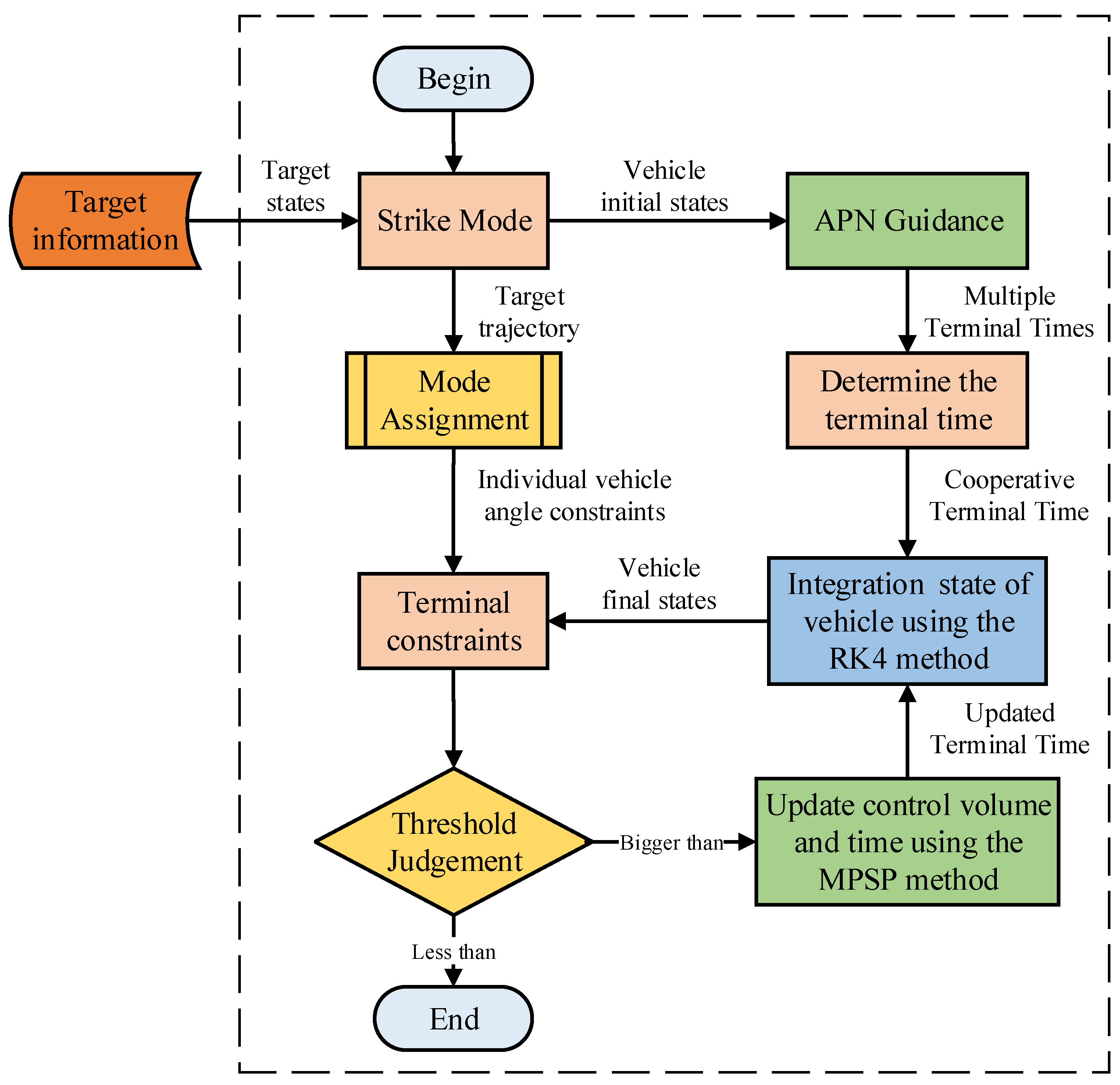
In this section, the guidance strategy is been established.The specific flow is shown in Figure 2. Notice that the method uses Euler’s algorithm for recursive operations and the 4th order Runge-Kutta method for prediction calculations of the simulation scenarios, and the junction of these two algorithms loses a certain amount of computational accuracy but effectively reduces the computation time.
Although the computational accuracy of the Euler algorithm is not as high as that of the RK4 method, a good discrete dynamics model can be obtained using the Euler method, and the coefficient matrices therein can be computed more efficiently. The computational time can also be further reduced by a reasonably chosen number of iterations in a guidance cycle.

4.1. Guess History Selection

In this paper, the Augmented Proportional Navigation (APN) guidance law is used to guess the initial control parameter and find a suitable control parameter U k , k = 1 , 2 , , N 1 . The following briefly describes the solution procedure of the conjectured control solution. Firstly, σ ˙ is defined as the three-dimensional realized rotational angular velocity of the vehicle and the target.
σ ˙ = r × d d t r r · r = 1 r 2 r y r ˙ z r z r ˙ y r z r ˙ x r x r ˙ z r x r ˙ y r y r ˙ x = σ ˙ x σ ˙ y σ ˙ z
The right vector in Equation (35) represents the component of the line-of-sight angular velocity in the inertial system. r x , r y , r z denote the components of the elastic distance in the inertial system, respectively. Next, transforming the line-of-sight rotational angular velocity into the velocity coordinate system, it can be expressed as:
σ ˙ p i t c h = σ ˙ x sin ψ m + σ ˙ z cos ψ m σ ˙ y a w = σ ˙ x sin θ m cos ψ m + σ ˙ z sin θ m sin ψ m + σ ˙ y cos θ m
where σ p i t c h , σ y a w denote the components of the line-of-sight angular velocity in the pitch and yaw planes, respectively. The relative approach velocity is V c , and the specific expression is
V c = r ˙ = r x r ˙ x + r y r ˙ y + r z r ˙ z r
Assuming that the pilot law ratio factor is N e , the commanded acceleration of the pitch and yaw channel is calculated from the APN
a y c = N e V c σ ˙ p i t c h + 1 2 a t p i t c h + g cos θ m , a z c = N e V c σ ˙ y a w + 1 2 a t y a w ,
where a y c , a z c denote the commanded values of the longitudinal and lateral acceleration, acting on the vehicles’ dynamics model through the first-order delay link.

4.2. Strike Mode Design

Another key step in the coordinated guidance strategy studied in this paper is the determination of the strike pattern. For a maneuvering target moves in the direction of ψ t (stationary target ψ t = 0 ), then the strike pattern is defined as follows:
  • For three vehicles, the terminal constraint angles are taken as
    ( γ d , ψ t 90 ) , ( γ d , ψ t ) , ( γ d , ψ t + 90 )
  • For four vehicles, the terminal constraint angles are taken as
    ( γ d , ψ t 90 ) , ( γ d , ψ t ) , ( γ d , ψ t + 90 ) , ( γ d + Δ γ d , ψ t )
  • For five vehicles, the terminal constraint angles are taken as
    ( γ d , ψ t 90 ) , ( γ d , ψ t ) , ( γ d , ψ t + 90 ) , ( γ d , ψ t + 180 ) , ( γ d + Δ γ d , ψ t )
Then, on the basis of APN guidance, the Euclidean distance between the end state of each vehicle and the specified end state constraints is calculated in turn. And the end state constraints of each vehicle are determined by ordering them in turn. That is, the vehicle with the longest flight time corresponds to the end constraint with the smallest difference to reduce the adjustment time, while the vehicle with the shortest original flight time has more time to adjust due to the increased flight time and corresponds to the end constraint with the largest difference.

4.3. Implementation of the Guidance Strategy

Based on the robustness study of the guidance law above, it can be seen that the settings of t f have a great influence on the performance of MPSP-based cooperative guidance law, which should be set by considering the conditions of initial position, velocity, and available overload. Generally speaking, it can be set as follows
  • Consider the mission characteristics of the multiple vehicles and set the ideal constraint angle γ d , ψ t is determined autonomously by the motion of the target.
  • Estimation of the flight time of each vehicle following APN guidance law, taking into account the effects of initial position and velocity perturbations. Choose the longest time of them as the initial terminal time for the MPSP algorithm.
    t f = m a x ( t i A P N )
  • Take the vehicle with the longest flight time and substitute the flight angle constraints, the improved MPSP algorithm is utilized to find the terminal time that satisfies the constraints.
    t n e w = t f + Δ t f
  • Finally, for the case of multiple vehicles flying in a coordinated manner, the coordinated time t * is chosen to be t n e w .
  • The initial conditions and constraint angles of all the vehicles are used to finalize the synergy time and the MPSP algorithm is utilized to obtain the required amount of control. This ensures that all the vehicles are able to meet the specified constraints and accomplish the cooperative flight mission.

5. Numerical Simulation and Analysis

In this section, multiple sets of simulation results considering terminal angle constraints will be presented. In order to validate the effectiveness of the MPSP guidance law in solving a variety of problems, the simulation analysis in this paper includes different scenarios of various types.The ITCG (Impact Time Control Guidance) methodology is used to compare the effectiveness of the cooperative guidance. The initial conditions of the vehicle engagement are given in Table 1.

5.1. Case 1: Stationary Target (Three Vehicles)

In this scenario, three vehicles are simultaneously dropped from different positions and each determines its own constraint angle.
Since the target is stationary, its terminal coordinate is X t = 0 , Y t = 0 so the heading angle of the target ψ t = 0 and the terminal constraint angles are taken as
( 45 , 0 + 90 ) , ( 45 , 0 ) , ( 45 , 0 90 )
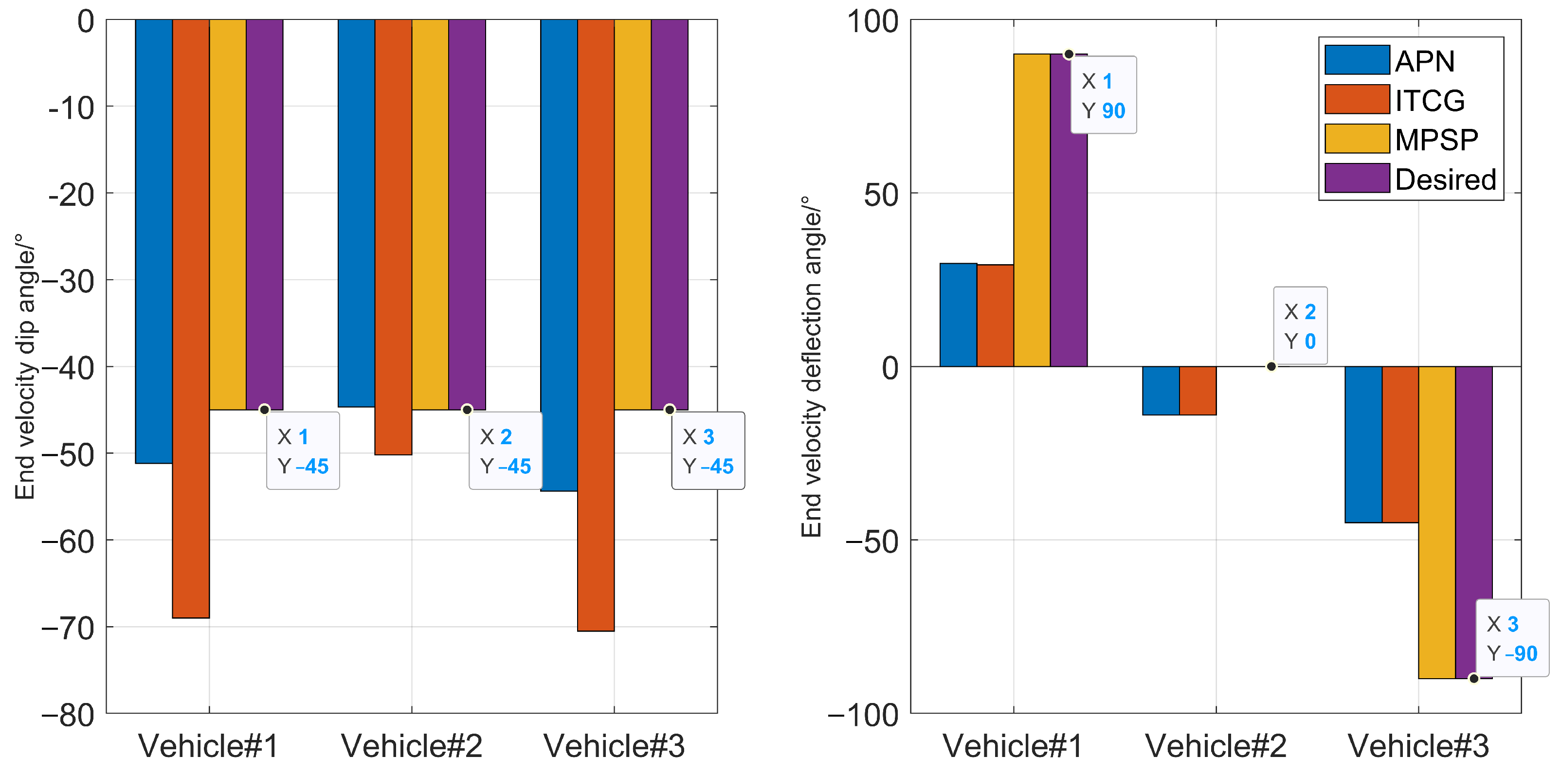
According to the method of determining the flight time described in the previous section, three vehicles are flown simultaneously to the designated target for various initial condition and with desired terminal constraints. The specific simulation data are shown in Table A1, the miss distances were observed to be less than 1 m.
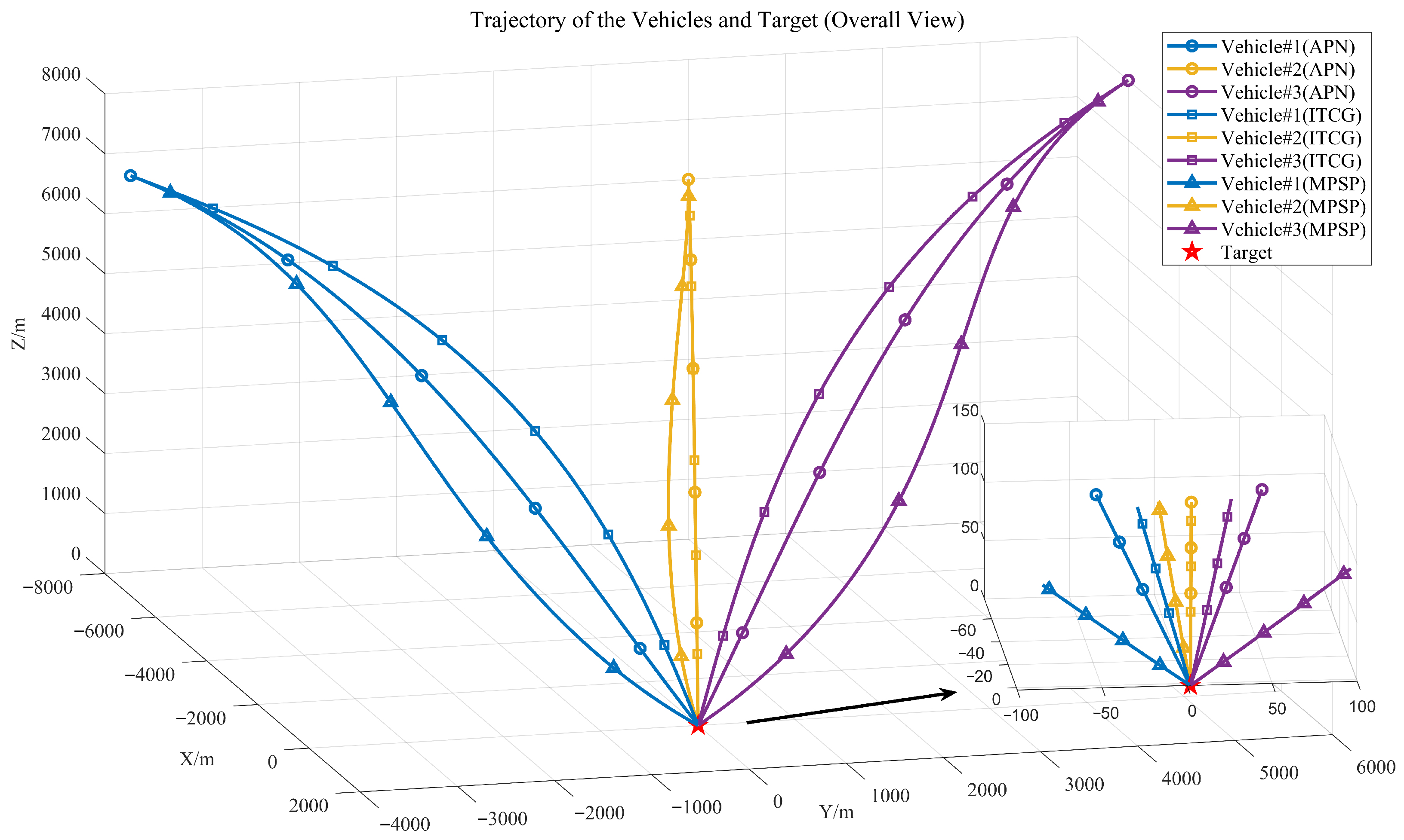
Figure 3 shows the vehicle trajectories in 3D view. Three different guidance methods are applied to the spacecraft. Among them, the APN is used to determine the flight time and provide initial control guesses to accelerate the convergence speed of the MPSP algorithm. It can be seen from the zoomed-in view in the lower right corner that all the vehicle can hit the target under the influence of different control methods. However, they arrive at different flight angles, including velocity dip angles and velocity deflection angles.
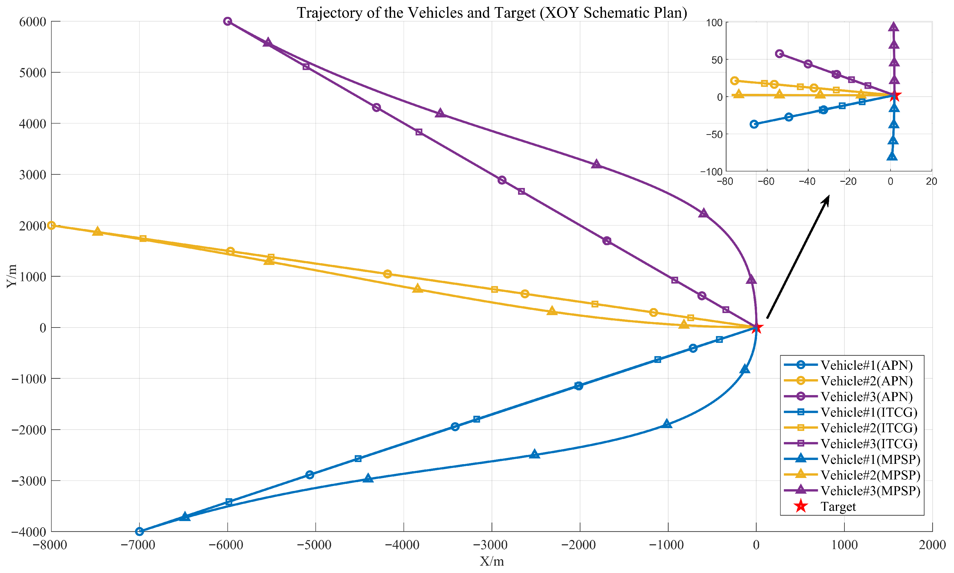
Figure 4 shows the trajectory of the vehicle in the XOY plane. We can clearly see that under the influence of the cooperative guidance framework proposed in this paper, the three vehicles reach the target with the specified terminal angle constraints.
Figure 5 shows the convergence of the flight state angle errors. Figure 6 compares the differences between the terminal states of the aircraft and the terminal constraints under different control methods. Under the influence of the cooperative guidance strategy proposed in this paper, the vehicle can meet the specified constraints with high precision. It is not difficult to see that the MPSP method can reduce the convergence error of the flight angles of all vehicle to below 0.1 within the specified time, while the ITCG method fails to do so.

5.2. Case 2: Maneuvering Target (Three Vehicles)

In this scenario, the initial states of the vehicle are the same as in Case 1, but the motion state of the target changes. For ease of description, we directly provide the end position of the target.
The terminal coordinate under ITCG and MPSP method is X t = 1027.15 , Y t = 590.52 and X t = 1088.10 , Y t = 565.77 . So the heading angle of the target ψ t = 20 . 21 and the terminal constraint angles are taken as
( 60 , 20 . 21 + 90 ) , ( 45 , 20 . 21 ) , ( 60 , 20 . 21 90 )
The target moves according to the manner described in previous section, and the motion trajectory is a curve. This increases the difficulty of cooperative guidance because both the arrival point and the terminal angle constraints of the aircraft will change with the movement of the target.The specific simulation data are shown in Table A2.
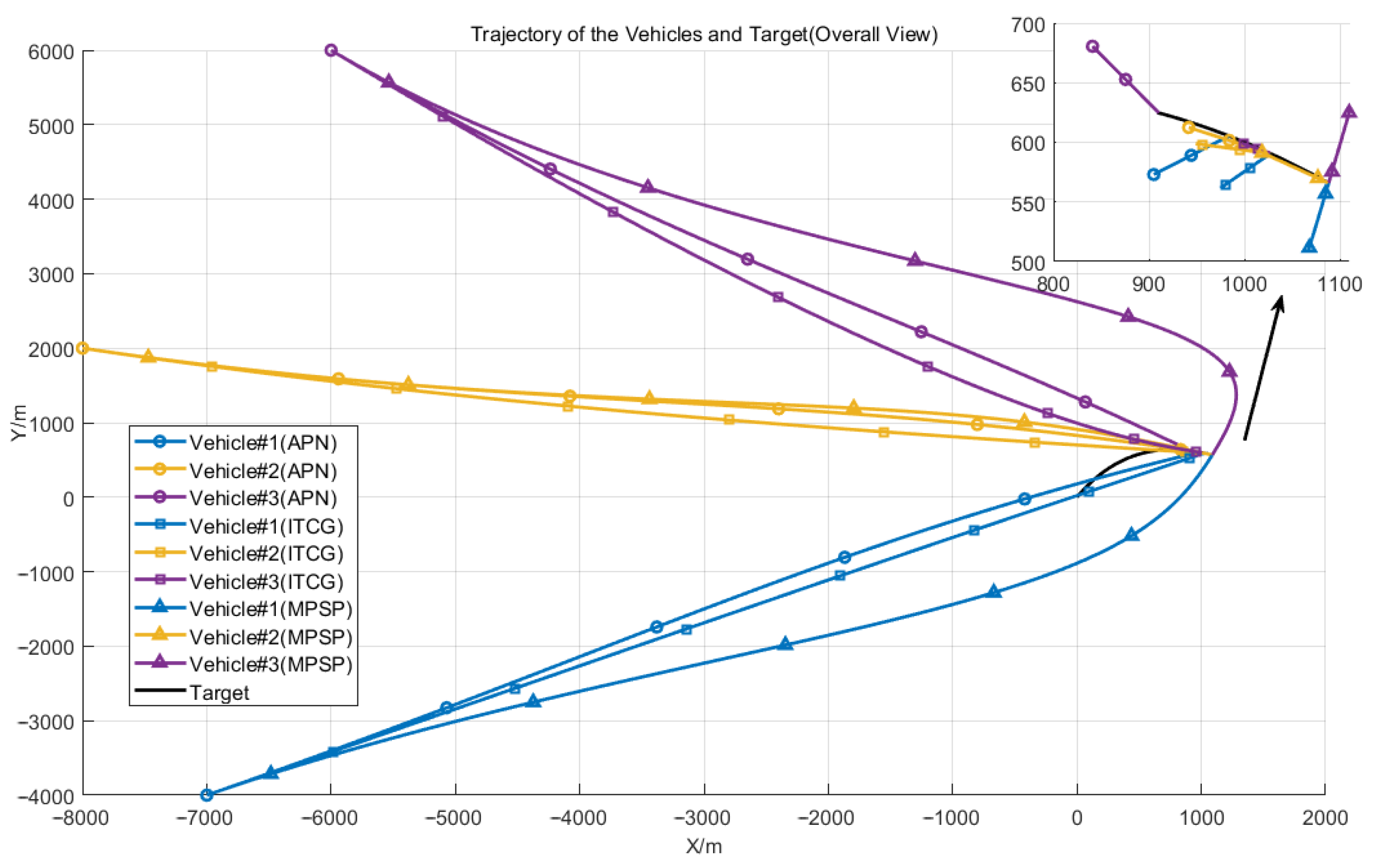
Since the initial states of the aircraft are different, the arrival times of the three aircraft using APN guidance are different. This can be observed in Figure 7. It is also for this reason that the terminal angle constraints of the aircraft are changing and even becoming more difficult to control. Compared with the coordination time of ITCG, in order to meet the constraints, the cooperation time of the MPSP method becomes longer under the influence of the adaptive algorithm proposed in this paper.
From the Figure 7, it can be observed that the vehicles guided by the APN method do not arrive simultaneously and fail to meet the angle constraints. However, it provides a perspective on the sequence of arrival, with Vehicle # 3 arriving first, followed by Vehicles # 1 and # 2 . Utilizing the ITCG method, based on the longest flight time, all three vehicles reach the target area simultaneously, yet still do not satisfy the angle constraints. Compared to Case 1, the difficulty of satisfying the constraints is increased due to the target’s movement, necessitating a longer adjustment time. Consequently, the guidance time based on the MPSP method is extended beyond the original longest vehicle flight time. Automatic adjustments are made to comply with the specified angle constraints.
Figure 8 shows the trajectory of the vehicle in the XOY plane. Through this view, we can visualize the different flight terminal velocity deflections. The terminal angle can be constrained to the formulated position by the MPSP technique. And this angular constraint is self-determined by the direction of motion of the target, which is perpendicular to the target direction, respectively.
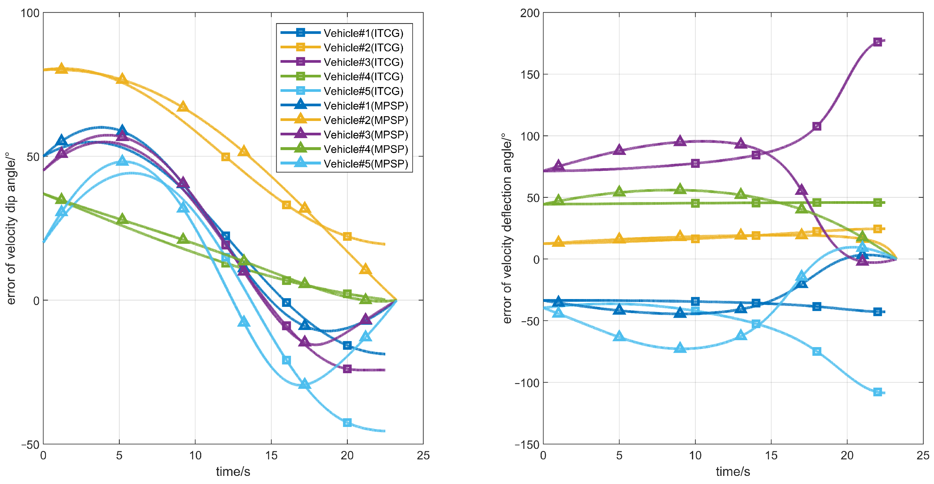
Consistent with the preceding paragraph, Figure 9 shows the convergence of the flight state angle errors. On closer inspection, it can be seen that the same vehicle will converge at different times under the action of different guidance methods. This just proves the effectiveness of the adaptive terminal time method proposed in this paper. Figure 10 compares the differences between the terminal states of the aircraft and the terminal constraints under different control methods. The terminal constraints are all as defined in the previous section.

5.3. Case 3: Maneuvering Target (Five Vehicles)

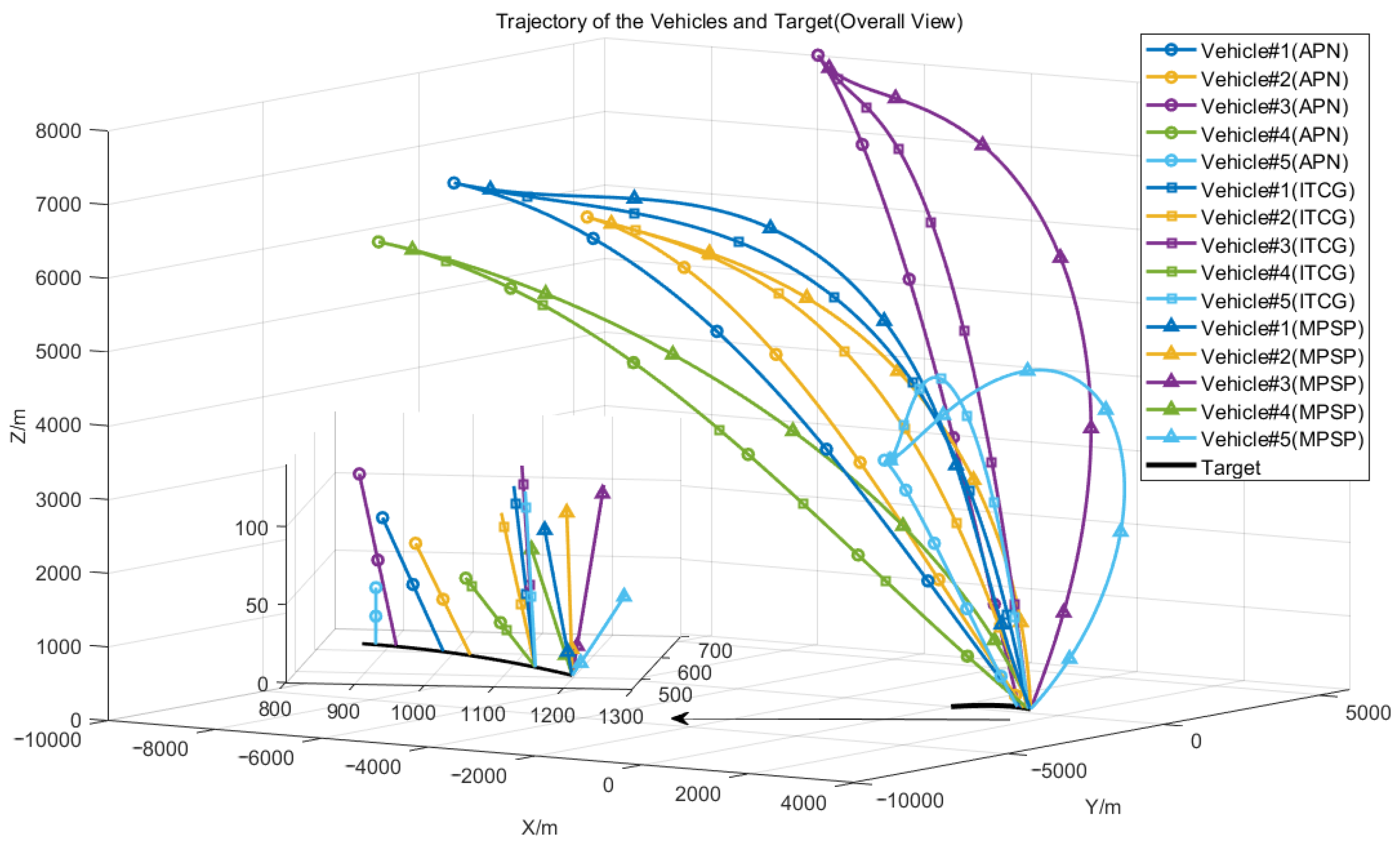
In this scenario, the the motion state of the target is the same as in Case 2, but the number of vehicles changed. Not only have two additional vehicles been added, but the method of guidance has also been changed. The mission type of one of the vehicles is intercept, not pursuit. The specific simulation data are shown in Table A3.
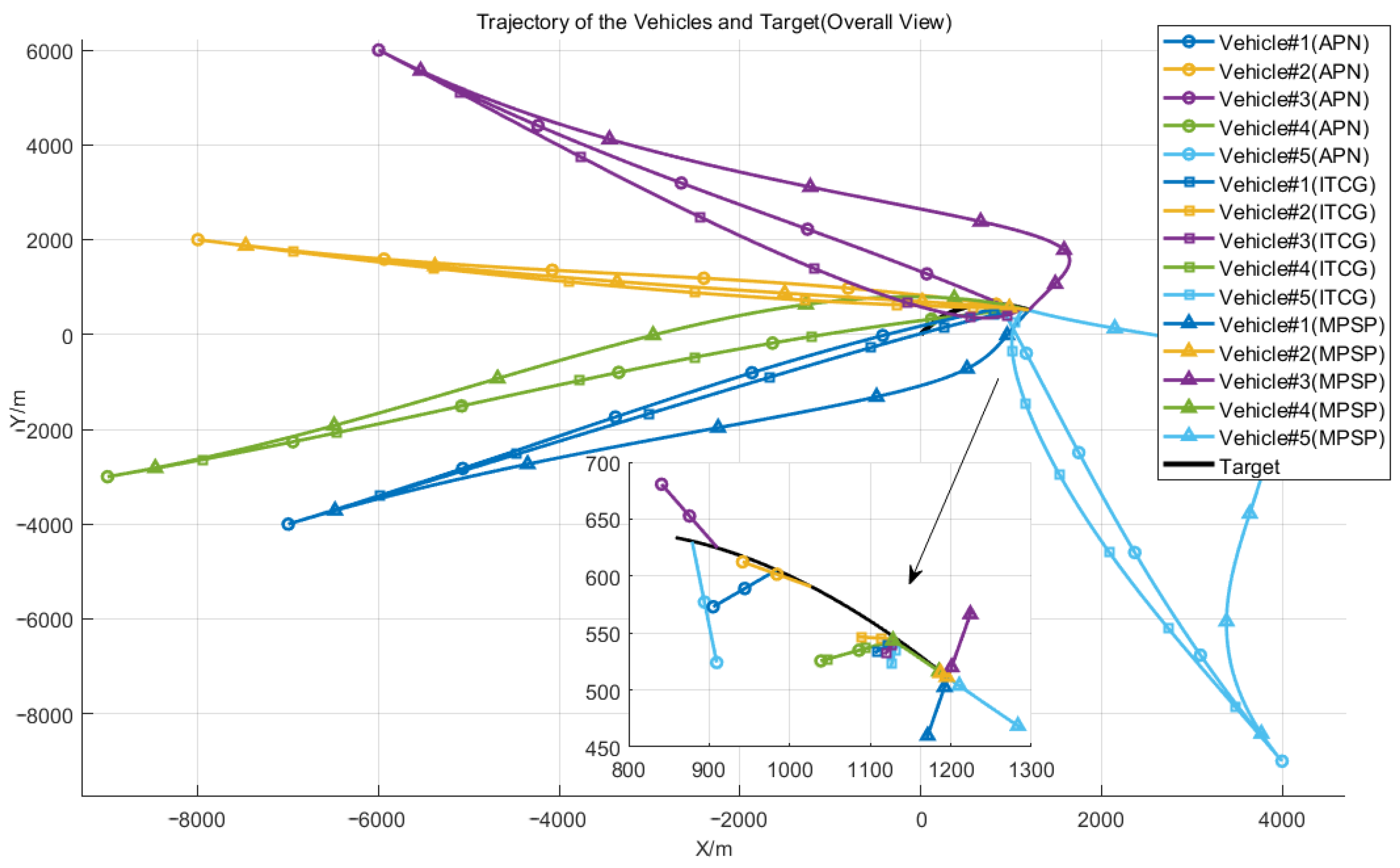
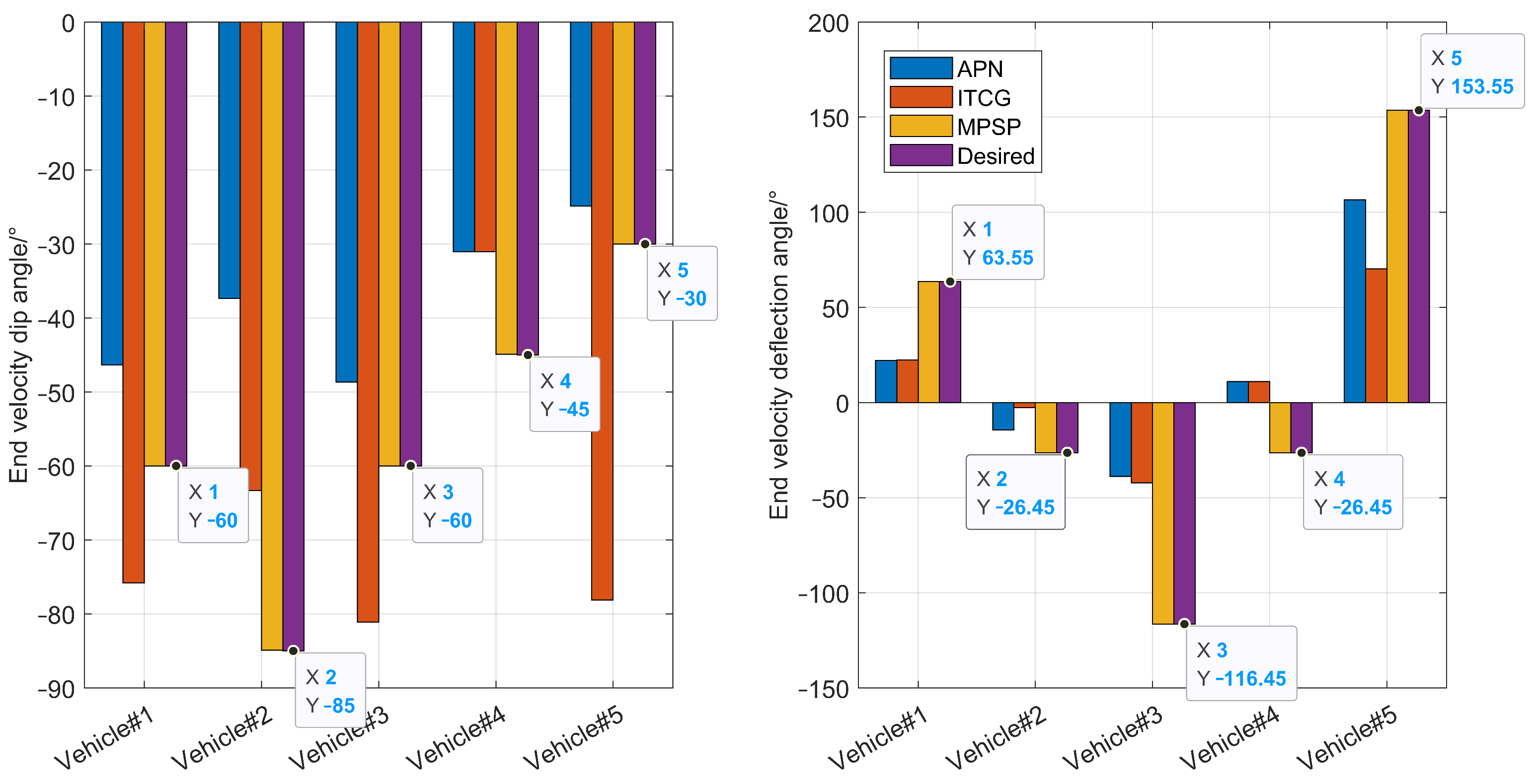
The terminal coordinate under ITCG and MPSP method is X t = 1133.72 , Y t = 544.30 and X t = 1196.41 , Y t = 510.88 . So the heading angle of the target ψ t = 26 . 45 and the terminal constraint angles are taken as
( 60 , 26 . 45 + 90 ) , ( 85 , 26 . 45 ) , ( 60 , 26 . 45 90 )
( 45 , 26 . 45 ) , ( 30 , 26 . 45 + 180 )
Through observation, it is not difficult to find that the missions of vehicle # 1 and vehicle # 3 are basically the same as those in Case 2. However, due to the addition of a new vehicle, it is more suitable for vehicle # 4 to perform the mission of vehicle # 2 in Case 2. This also reflects that the cooperative guidance strategy designed in this paper has the function of task allocation, which in turn can facilitate adaptive terminal time.
From the Figure 11, we can find that unlike Case 2, this time there are five vehicles executing the mission, which have also successfully completed the task while satisfying the constraints. Moreover, the control time has changed again due to the addition of new vehicles.
Figure 12 shows the trajectory of the vehicle in the XOY plane. Unlike Case 2, due to the addition of two more vehicles, the mission requirements have changed, and the tracking angles towards the target have also been altered. Under these circumstances, the flight time has been automatically adjusted, and the tasks for each vehicle have been redistributed. With the constraints satisfied, all vehicles have reached their designated positions, completing the mission at the prescribed angles.
Consistent with the preceding paragraph, Figure 13 shows the convergence of the flight state angle errors. On closer inspection, it can be seen that the same vehicle will converge at different times under the action of different guidance methods. This just proves the effectiveness of the adaptive terminal time method proposed in this paper. Figure 14 compares the differences between the terminal states of the aircraft and the terminal constraints under different control methods. The terminal constraints are all as defined in the previous section.
Figure 15 shows the off-target range of different control methods in all scenarios. Off-target range is an important indicator for evaluating guidance and control performance, representing the deviation between the actual arrival position of the vehicle and the target position. Through observation, it can be found that the MPSP method achieves the smallest miss distance in various scenarios, proving that the guidance accuracy of this method is superior to other methods. This result indicates that the cooperative guidance strategy designed in this paper can effectively guide aircraft to hit targets with high precision.

6. Conclusions

This paper presents a guidance strategy that automatically allocates tasks based on the target’s motion patterns, specifically considering different arrival angle constraints. By utilizing the improved MPSP method, the vehicles achieve coordinated flight, arriving simultaneously at the designated location while satisfying their individual angle constraints. Furthermore, the strategy adjusts arrival times automatically to meet all flight constraints. Simulation results demonstrate that all vehicles successfully complete the cooperative arrival when accurate target motion information is available. The guidance command gradually converges, creating favorable conditions for handover. The integrated application of this guidance strategy effectively solves the problem of coordinated vehicle arrival under specified constraints. This paper assumes that there is no communication among the vehicles, Therefore, future research will focus on studying closed-loop cooperative guidance methods based on inter-vehicle communication.

Author Contributions

Conceptualization, A.L. and X.H.; methodology, A.L. and X.H.; software, A.L. and S.Y.; formal analysis, A.L. and K.D.; writing—original draft preparation, A.L. and X.H.; writing—review and editing, A.L., X.H., S.Y. and K.D. All authors have read and agreed to the published version of the manuscript.

Funding

This research was supported by the National Natural Science Foundation of China, Grant Number:62073265.

Data Availability Statement

The raw data supporting the conclusions of this article will be made available by the authors on request.

Acknowledgments

The authors are thankful to the anonymous reviewers for their useful suggestions.

Conflicts of Interest

The authors declare no conflict of interest.

Appendix A

Table A1. Specific simulation data in case 1.
      Guidance MethodVehicle 1Vehicle 2Vehicle 3
Flight Time/sAPN18.16919.11618.273
ITCG19.11619.11619.116
MPSP19.11619.11619.116
End γ /degConstraint−45−45−45
APN−51.19−44.69−54.39
ITCG−69.00−50.20−70.51
MPSP−45.00−45.00−45.00
End ψ /degConstraint909090
APN29.64−14.03−44.97
ITCG29.30−14.03−44.96
MPSP90.000.00−90.00
Off−target range/mAPN0.80120.69870.4515
ITCG0.20950.25110.2746
MPSP0.22100.27010.2491
Table A2. Specific simulation data in case 2.
      Guidance MethodVehicle 1Vehicle 2Vehicle 3
Flight Time/sAPN19.72720.45018.487
ITCG20.45020.45020.450
MPSP21.45121.45121.451
End γ /degConstraint−60−45−60
APN−46.35−37.36−48.66
ITCG−60.94−45.09−76.55
MPSP−60−45−60
End ψ /degConstraint69.79−20.21−110.21
APN22.18−14.47−38.89
ITCG28.88−6.092−15.47
MPSP69.79−20.21−110.21
Off-target range/mAPN0.55350.57350.3968
ITCG0.39250.17650.6155
MPSP0.10970.07610.1236
Table A3. Specific simulation data in case 3.
      Guidance MethodVehicle 1Vehicle 2Vehicle 3Vehicle 4Vehicle 5
Flight Time/sAPN19.72720.45018.48722.18817.942
ITCG22.18822.18822.18822.18822.188
MPSP23.18723.18723.18723.18723.187
End γ /degConstraint−60−85−60−45−30
APN−46.35−37.36−48.66−31.03−24.87
ITCG−75.83−63.33−81.11−31.0378.12
MPSP−60−84.99−60.00−44.99−30.00
End ψ /degConstraintt63.55−26.45−116.45−26.45153.55
APN22.18−14.47−38.8911.07106.05
ITCG22.41−2.57−42.1811.0770.20
MPSP63.55−26.46−116.46−26.45153.55
off-target range/mAPN0.55350.57350.39680.50600.4810
ITCG0.46030.59990.88241.06810.7159
MPSP0.6860.11660.18780.07560.1318

References

  1. Hou, Z.; Lei, T. Constrained model free adaptive predictive perimeter control and route guidance for multi-region urban traffic systems. IEEE Trans. Intell. Transp. Syst. 2020, 23, 912–924. [Google Scholar] [CrossRef]
  2. Gao, Y.; Wang, D.; Wei, W.; Yu, Q.; Liu, X.; Wei, Y. Constrained Predictive Tracking Control for Unmanned Hexapod Robot with Tripod Gait. Drones 2022, 6, 246. [Google Scholar] [CrossRef]
  3. Rout, R.; Subudhi, B. Design of line-of-sight guidance law and a constrained optimal controller for an autonomous underwater vehicle. IEEE Trans. Circuits Syst. II Express Briefs 2020, 68, 416–420. [Google Scholar] [CrossRef]
  4. Hou, Z.; Yang, Y.; Liu, L.; Wang, Y. Terminal sliding mode control based impact time and angle constrained guidance. Aerosp. Sci. Technol. 2019, 93, 105142. [Google Scholar] [CrossRef]
  5. You, H.; Chang, X.; Zhao, J.; Wang, S.; Zhang, Y. Three-dimensional impact-angle-constrained cooperative guidance strategy against maneuvering target. ISA Trans. 2023, 138, 262–280. [Google Scholar] [CrossRef] [PubMed]
  6. Yu, X.; Luo, S.; Liu, H. Integrated Design of Multi-Constrained Snake Maneuver Surge Guidance Control for Hypersonic Vehicles in the Dive Segment. Aerospace 2023, 10, 765. [Google Scholar] [CrossRef]
  7. Shi, P.; Guan, S.; Cheng, L.; Li, W.; Huang, X. Real-time Multi-Constrained Polynomial Guidance Based on Analytical Gradient Derivation. IEEE Trans. Aerosp. Electron. Syst. 2023. early access. [Google Scholar]
  8. Xiao, B.; Wu, X.; Cao, L.; Hu, X. Prescribed Time Attitude Tracking Control of Spacecraft With Arbitrary Disturbance. IEEE Trans. Aerosp. Electron. Syst. 2022, 58, 2531–2540. [Google Scholar] [CrossRef]
  9. Ye, Q.; Liu, C.; Sun, J. A backstepping-based guidance law for an exoatmospheric missile with impact angle constraint. IEEE Trans. Aerosp. Electron. Syst. 2018, 55, 547–561. [Google Scholar] [CrossRef]
  10. Yan, X.; Zhu, J.; Kuang, M.; Yuan, X. A computational-geometry-based 3-dimensional guidance law to control impact time and angle. Aerosp. Sci. Technol. 2020, 98, 105672. [Google Scholar] [CrossRef]
  11. Jiang, S.; Tian, F.q.; Sun, S.y.; Liang, W.g. Integrated guidance and control of guided projectile with multiple constraints based on fuzzy adaptive and dynamic surface. Def. Technol. 2020, 16, 1130–1141. [Google Scholar] [CrossRef]
  12. Kim, H.G.; Lee, J.Y.; Kim, H.J.; Kwon, H.H.; Park, J.S. Look-angle-shaping guidance law for impact angle and time control with field-of-view constraint. IEEE Trans. Aerosp. Electron. Syst. 2019, 56, 1602–1612. [Google Scholar] [CrossRef]
  13. Lin, M.; Ding, X.; Wang, C.; Liang, L.; Wang, J. Three-dimensional fixed-time cooperative guidance law with impact angle constraint and prespecified impact time. IEEE Access 2021, 9, 29755–29763. [Google Scholar] [CrossRef]
  14. Yang, X.; Song, S. Three-dimensional consensus algorithm for nonsingular distributed cooperative guidance strategy. Aerosp. Sci. Technol. 2021, 118, 106958. [Google Scholar] [CrossRef]
  15. Zhang, S.; Guo, Y.; Liu, Z.; Wang, S.; Hu, X. Finite-time cooperative guidance strategy for impact angle and time control. IEEE Trans. Aerosp. Electron. Syst. 2020, 57, 806–819. [Google Scholar] [CrossRef]
  16. Wang, J.; Ding, X.; Wang, C.; Xia, K.; Xin, M. Look angle tracking based three-dimensional impact time control guidance law with field-of-view constraint. Int. J. Robust Nonlinear Control. 2023, 33, 9951–9968. [Google Scholar] [CrossRef]
  17. Padhi, R. Model predictive static programming: A promising technique for optimal missile guidance. Ann. Indian Natl. Acad. Eng. 2008, 5, 186–194. [Google Scholar]
  18. Li, Y.; Zhou, H.; Chen, W. Three-dimensional impact time and angle control guidance based on MPSP. Int. J. Aerosp. Eng. 2019, 2019, 5631723. [Google Scholar] [CrossRef]
  19. Maity, A.; Padhi, R.; Mallaram, S.; Rao, G.M.; Manickavasagam, M. A robust and high precision optimal explicit guidance scheme for solid motor propelled launch vehicles with thrust and drag uncertainty. Int. J. Syst. Sci. 2016, 47, 3078–3097. [Google Scholar] [CrossRef]
  20. Zha, Y.; Guo, J.; Zheng, H.; Kang, H.; Yu, L. Improved MPSP Guidance Law Design for Achieving Expected Attack Time. In Proceedings of the 2020 International Symposium on Autonomous Systems (ISAS), Guangzhou, China, 6–8 December 2020; pp. 29–34. [Google Scholar]
  21. Duvvuru, R.; Maity, A.; Umakant, J. Three-dimensional field of view and impact angle constrained guidance with terminal speed maximization. Aerosp. Sci. Technol. 2022, 126, 107552. [Google Scholar] [CrossRef]
  22. Wang, Z.; Wang, X.; Lin, H. A cooperative guidance law with constraints of impact time and impact angle. J. Ballist. 2017, 29, 1–8. [Google Scholar]
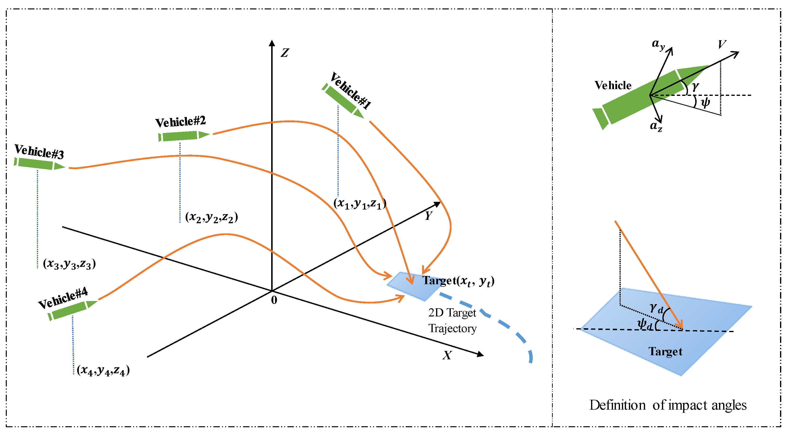
Figure 1. 3D engagement geometry of cooperation flight and definition of impact angle.
Drones 08 00134 g001
Figure 2. Cooperative guidance strategy framework.
Drones 08 00134 g002
Figure 3. Trajectory of the vehicles and magnification in overall view (Case 1).
Drones 08 00134 g003
Figure 4. Trajectory of the vehicles and magnification in XOY plane (Case 1).
Drones 08 00134 g004
Figure 5. Error of attitude angles change over time (Case 1).
Drones 08 00134 g005
Figure 6. Comparison of terminal states under different control methods (Case 1).
Drones 08 00134 g006
Figure 7. Trajectory of the vehicles and magnification in overall view (Case 2).
Drones 08 00134 g007
Figure 8. Trajectory of the vehicles and magnification in XOY plane (Case 2).
Drones 08 00134 g008
Figure 9. Error of attitude angles change over time (Case 2).
Drones 08 00134 g009
Figure 10. Comparison of terminal states under different control methods (Case 2).
Drones 08 00134 g010
Figure 11. Trajectory of the vehicles and magnification in overall view (Case 3).
Drones 08 00134 g011
Figure 12. Trajectory of the vehicles and magnification in XOY plane (Case 3).
Drones 08 00134 g012
Figure 13. Error of attitude angles change over time (Case 3).
Drones 08 00134 g013
Figure 14. Comparison of terminal states under different control methods (Case 3).
Drones 08 00134 g014
Figure 15. Comparison of off-target range under different control methods in all cases.
Drones 08 00134 g015
Table 1. Initial conditions of the vehicle engagement.
      Vehicle1Vehicle2Vehicle3Vehicle4Vehicle5
Position (x,y,z) (km)(−7,−4,7)(−8,2,6)(−6,6,8)(−9,−3,6)(4,−9,4)
V (m/s)600550650570630
γ (deg)−10−5−15−8−10
ψ (deg)30−14−4518114
Mission TypePursuitPursuitPursuitPursuitIntercept
Disclaimer/Publisher’s Note: The statements, opinions and data contained in all publications are solely those of the individual author(s) and contributor(s) and not of MDPI and/or the editor(s). MDPI and/or the editor(s) disclaim responsibility for any injury to people or property resulting from any ideas, methods, instructions or products referred to in the content.