1. Introduction
Unmanned Aerial Vehicles (UAVs) have attracted significant attention as a viable substitute for manned operations. The ability to operate in hazardous environments without risks for human operators, combined with the cost-effectiveness of operations, has propelled UAVs into one of the most rapidly expanding domains. In fact, the number of drones and unmanned operations is expected to double by 2025 [
1,
2].
To fully exploit the potential of UAVs and improve mission efficiency, a key challenge is planning paths in complex and unstructured environments.
Nevertheless, path planning presents a challenge due to the inherent complexity of environments. This issue is commonly framed as an optimization problem, where the definition of the shortest path involves a sequence of waypoints. These waypoints must be chosen considering the presence of obstacles, no-fly zones, non-cooperative aircraft, and limitations from flight mechanics [
3,
4]
In the literature, several publications explored the definition of three-dimensional trajectories by decoupling planar maneuvers from altitude changes [
5,
6]. Extensive research addressed two-dimensional (or decoupled three-dimensional) aerial path planning issues, sharing algorithms and solutions with the fields of robotics and automotive science.
Literature reviews on UAV path planning classify methods into variational, optimal control, geometrical, graph optimization, artificial potential field, and natural optimization. While the variational approach to path planning is considered natural [
7,
8], its application becomes challenging in complex scenarios with flight dynamics constraints.
Optimal control serves as an alternative, involving a closed-loop algorithm with convergence to a local sub-optimal trajectory. In [
9], the authors addressed the challenge of flying a helicopter with a slung load by formulating an optimal control problem, using trajectories as references to a state feedback controller. Pseudospectral optimal control [
10] was also used for unmanned helicopters, to plan minimum-time trajectory in environments with obstacles. The authors of [
11] introduced a Distributed Model Predictive Controller (DMPC) for UAV guidance, taking into account anticollision constraints in accordance with the International Civil Aviation Organization (ICAO) Right of Way rules. However, optimal control may be ineffective in finding a global optimum, as it demands significant computational capabilities, especially when employing non-linear optimization algorithms.
Several publications [
12,
13] introduced purely geometrical approaches, describing paths as sequences of segments, arcs, or template curves. Examples include solutions to Dubins’ car problem [
14,
15] or clothoid curves [
16,
17]. However, such solutions often require combining other algorithms to account for obstacles and no-fly zones.
Graph optimization is an effective strategy for designing edges using geometrical methods. In these approaches, the environment needs to be discretized using regular or irregular grids [
18]. Alternatives include Visibility Graphs [
19,
20,
21], Voronoi diagrams [
22,
23], Rapidly Exploring Random Trees (RRT) [
24,
25,
26], Tangent Graphs [
27], Sparse Tangential Networks (SPARTAN) [
28], and road maps [
29,
30].
In order to determine the most efficient route across graphs, ensuring consistent and reproducible outcomes in expansive settings, widely recognized heuristics like Dijkstra’s algorithm [
31], A* [
32,
33], and D* [
34] are frequently employed. However, these algorithms do not guarantee the shortest path in continuous space. Indeed, in [
35], the Theta* approach was introduced, which outperformed several solutions based on A*, A* with post-smoothing [
36], and the so-called Field D* [
37], in terms of path length and computation time. The Theta* algorithm represents an improvement over A* and it is particularly useful in scenarios where agents need to find the shortest path through a continuous space. Theta* allows for a more flexible search by moving along directions, minimizing heading changes. Ref. [
38] presented a grid map-based path-planning algorithm, based on Theta*, for the real-time generation of realistic paths, taking into account both the heading angle and the angular rate of unmanned surface vehicles (USVs). To improve A*, in [
33], the authors proposed a Theta*-based procedure applied to orographic obstacles and urban environments, in order to evaluate the solution for different kinds of obstacles. In [
39], a revised and adapted Lazy Theta* path-planning algorithm was presented, reducing the dimension of the problem and using a sparse resolution grid in the form of an octree, in order to generate paths in large 3D scenarios in real-time.
In robot motion planning problems, kinodynamic path searching methods have been adopted to satisfy kinematic and dynamic constraints. In particular, several hybrid A* algorithms [
40,
41,
42] combine the benefits of A* search in continuous space with a discretized set of headings in order to obtain feasible trajectories for autonomous vehicles navigating in unknown environments. In [
43], the authors proposed a hierarchical path-planning architecture for UAVs, consisting of an A* path-search step followed by B-Spline trajectory optimization. In [
44], the authors proposed an improved A* and a path pruning method to generate safe guiding trajectories for quadrotor UAVs. Another example is the Kinodynamic RRT* (KRRT*) algorithm, first introduced in [
45], where the authors extended the capabilities of RRT* to obtain smoother trajectories for robot motion planning with linear differential constraints. In [
46], the authors presented an application of this approach, named Multi-robot Kinodynamic RRT* (MK-RRT*), to the path-planning problem for a fleet of UAVs, testing their algorithm in real-world experiments. Alternatively, the authors in [
47] employed the KRRT* to plan trajectories for fixed-wing UAVs in complex terrain environments.
In the context of guidance algorithms with real-time requirements, the techniques based on Artificial Potential Field have proven to be highly effective [
48,
49,
50]. However, increasing the number of obstacles or potential sources in the environment raises the likelihood of encountering singularities, which need a strategy to find a solution.
Natural optimization methods enable the creation of sophisticated models [
51,
52] based on flight dynamics, where a sequence of feasible maneuvers is optimized to reach the target point. In [
53], the authors proposed a technique for creating continuously parameterized classes of feasible trajectories, made of a small collection of user-provided example motions. An incremental path-planning algorithm for autonomous vehicles flying in an environment with moving obstacles able to take into account flight dynamics was presented in [
54]. Furthermore, a trajectory planning model, coupled with a Particle Swarm Optimizer (PSO) [
55] was able to identify optimal UAV flight trajectories compliant with environmental constraints. Nevertheless, these methods are computationally expensive and slow, making them only suitable for offline optimization applications.
This article introduces a novel approach to the path planning of a fixed-wing aircraft. The trajectory is defined as a piece-wise curve made of segments, circular and spiral arcs between two prescribed points, with assigned initial and target directions. To ensure compliance with aircraft performance constraints, the heading variation between two directions is made by defining an Euler spiral-based path transition curve made of two spirals and a circular arc, where the maximum curvature and the maximum change in curvature depend on the aircraft characteristics. The final path is optimized by using an evolution of the Theta* algorithm, whose arcs between nodes are the above defined path-transition curves. In this manner, the final trajectory is free of discontinuities and proves to be entirely flyable by the aircraft. This approach is an important enhancement with respect to previous works that adopt Dubins arcs to smooth the path, introducing a discontinuity in the curvature between straight segments and circular arcs. The transition between lines with discontinuous curvature requires a step in the yaw rate, and, consequently, in the bank angle, which is impossible due to flight dynamics constraints. To enhance the performance of the presented algorithm, the exploration distance of Theta*, which is useful to exploit the search space, is variable, taking into account the actual distance to obstacles. Additionally, in order to avoid unnecessary areas and prevent excessive maneuvers, Theta* explores the search space using a vision cone, the extent of which is a parameter of the algorithm.
The manuscript is structured as follows:
Section 2 introduces the path transition curve as a solution to path planning in the absence of obstacles.
Section 3 outlines the Theta*-based path-planning algorithm, incorporating the concept of smooth transitions between edges linking nodes. In
Section 4, several numerical results are presented to prove the effectiveness of the proposed approach, incorporating a comparative analysis of several implemented versions of Theta*.
Section 5 introduces a numerical comparison of the Theta*-based algorithm with three state-of-the-art planners in order to highlight the pros and cons of the proposed methodology. Finally,
Section 6 provides a concise summary of the conclusions drawn from the current study.
2. Path Transition Curve
A standard flight path, navigating through a sequence of waypoints, comprises linear and circular trajectory segments [
56]. In fixed-wing aircraft, the transition between these segments poses challenges due to inherent path curvature discontinuity, requiring an immediate shift in yaw rate and bank angle. Flight dynamics prerequisites stress the need for continuous curvature paths within specified bounds for precise tracking [
57,
58]. Euler spirals or clothoids, based on a linear 2D dynamic aircraft model, offer a linear curvature and arc length relationship, making them apt for geometrically determining the flight path during optimization.
The model simulates non-steady constant altitude turns for altering aircraft heading and estimating fuel consumption. This study focuses on coordinated turns with zero sideslip angle, where the velocity vector consistently lies in the plane of symmetry. Heading angle () and roll angular velocity () are key parameters, and motion is confined to a horizontal plane.
Considering quasi-steady turns, the following simplifications can be employed: (a) a negligible change in velocity (), (b) a negligible component of thrust normal to the flight path, and (c) a constant weight.
The angle of attack (
), drag (
D), thrust (
T), and specific fuel consumption (
C) can be considered as functional relationships of the form:
where
h is the altitude and
P is the engine power.
The equations of motion can be formulated in terms of speed (
V) and heading angle (
) as follows:
These eight equations are based on ten variables (six states: , and four controls: ).
Considering subsonic speed, the drag polar can be approximated with a parabolic function with constant coefficients as follows:
where
and
K are constants and
is the lift coefficient that can be computed as
From this model, it is possible to establish the curvature and the sharpness of the trajectory during a turn maneuver. Considering a typical circular motion of radius
r, whose model is given by
with the centripetal force
, the turn radius can be deduced as follows:
where
is the air density and
represents the wing loading. However, because
, the turn radius can be written as dependent on only the speed (
) and the bank angle
.
At constant speed, the minimum turn radius
can be obtained when
is maximum, taking into account the maximum load factor
compliant with the maximum available thrust and the structural limits of the aircraft:
Because the curvature
k is inversely proportional to the curvature radius, a path is valid if the curvature is smaller than the specified maximum value
where
denotes the maximum curvature.
The maximum sharpness can be found by differentiating the curvature function with respect to time:
Since the curvature of a spiral is linear along the curve, the minimum and maximum curvature occur at the tips of the clothoid segment.
Flight Path Transition Curve between Two Directions
Consider two straight lines, denoted as and intersecting at a point Q, that define the desired headings for an aircraft, represented by and , respectively.
A flight path transition curve between these intersecting straight lines can be computed using two clothoids and an arc (coordinated turn), if necessary. The presence of such a circular arc must be taken into account, considering any constraints on the aircraft roll rate. This definition can be regarded as an alternative to the Dubins path [
14], achieved by smoothing the tips of the circular arc to avoid curvature discontinuities.
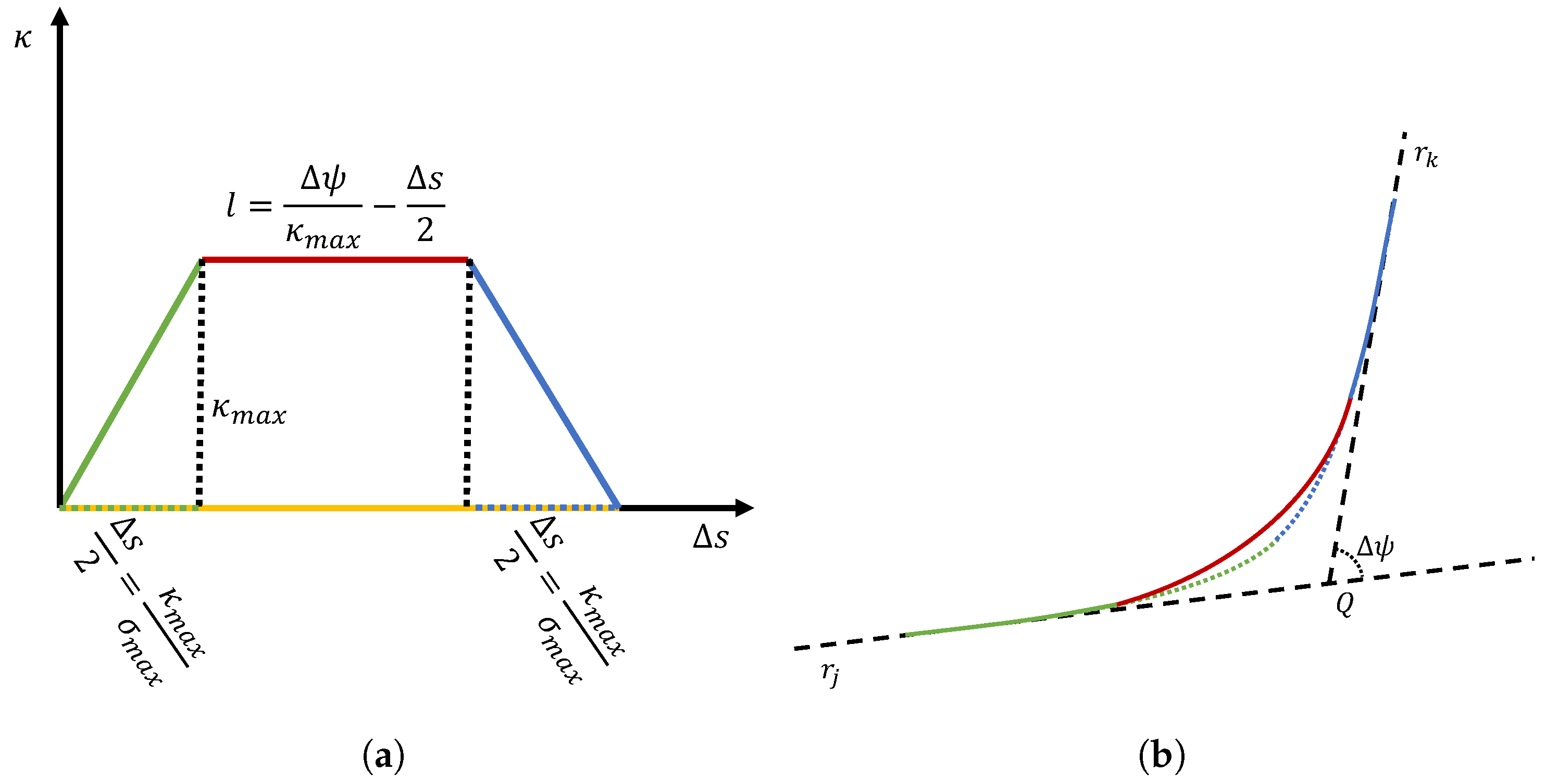
With reference to
Figure 1, achieving the transition from the linear trajectory, defined by
, to the circular arc involves a curvature increment from zero to
. Subsequently, the curvature remains constant until another transition occurs between the arc and the final direction
, characterized by a curvature decrease from
to zero.
Procedure 1. Flight path transition curve between two directions
STEP 1. Firstly, compute the angles and between an arbitrary axis and and , respectively.
STEP 2. Assuming , the maximum curvature and the maximum sharpness, it is possible to compute , as the length of a virtual curve with maximum sharpness and maximum curvature. It is worth noting that it is called virtual because the heading change constraint is not considered yet.
STEP 3. The area of the trapezium with major base
, minor base
l as the length of the circular arc, and height
must be equal to
. The minor base can be computed as
If , the path includes a circular arc with curvature . If , then the path includes only two clothoids and the maximum curvature is reached at the middle point. If , the path includes only two clothoids that do not reach the maximum curvature.
STEP 4. Starting from the intersection point
, the path can be computed by integrating the following equations as follows:
- -
For the half-circular arc, the initial conditions are , , while and .
- -
For the spiral curve, in the case of (), the initial conditions are , (, ), while and .
These segments represent the second half of the overall curve. The first part can be computed by mirroring the results with respect to the median line between the considered directions. The set of Equation (
9) has been employed to mitigate non-linearities in the calculation of heading variation
. This implies that, in the simulation of aircraft motion, the variation law of the bank angle
can be computed as follows:
STEP 5. The curve must be moved in order to be tangent to both the assigned directions.
3. Path-Planning Algorithm
Given a starting point A with a prescribed initial direction , a target point B, with a prescribed final direction , and a set of obstacles, the optimal flyable path is a smoothed curve, with continuous curvature , composed of segments and flight path transition curves that does not cross any obstacle, passing through several waypoints in the free space.
Its construction involves the use of an optimization algorithm to find the optimal sequence of waypoints . In this paper, a heuristic algorithm Theta* has been modified to generate flyable paths.
The genesis of Theta* can be attributed to A. Nash [
35], who originally introduced it as an extension of the A* algorithm. A* is a path-planning approach, primarily preferred for its effectiveness and simplicity of implementation. However, it imposes a limitation on the heading variation, which is typically constrained to multiples of 45°. This restriction, due to the grid-based movement, often results in a path deviating from the true shortest route with several changes in the heading of the vehicle.
Theta* emerged to overcome the A* constraints, particularly the grid-dependent path limitation governing heading variations. It explores the search space similarly to A*, but it optimizes the path during exploration to avoid unnecessary changes in the trajectory direction. However, flight paths resulting from both A* and Theta* appear as piecewise linear trajectories that are not compliant with the aircraft flight mechanics constraints.
The proposed procedure avoids the need for smoothing in the post-processing phase, allowing the aircraft performance constraints to be taken into account directly in the trajectory optimization process. While in its classical formulation, the arc connecting two points, and , is a straight segment, the proposed solution considers a flyable edge with continuous curvature , made of three parts: an initial straight segment starting in , a flight path transition curve with a starting direction , and a segment connecting the ending point of the transition curve and the node , with a direction that must be computed in order to minimize the overall length.
The procedure to connect the node with direction and the node is the following.
Procedure 2. Flyable edge between two points , with direction , and .
STEP 0—Set an initial guess for the building distance .
STEP 1—Consider a point
to be used as the intersection point between the direction
and the candidate direction
such that
where
is the heading angle to describe the direction
, and
and
are the coordinates of the point
(see
Figure 2a).
STEP 2—Compute as the direction .
STEP 3—Build the transition curve using Procedure 1.
STEP 4—Add two segments: the former connecting with the initial point of the transition curve and the latter connecting the ending point of the transition curve with .
STEP 5—Compute the length of the first segment of the just-built flyable path between and .
STEP 6—If
, then
and return to STEP 1 (see
Figure 2b, otherwise return the obtained flyable path
and the final direction
.
In the original Theta* algorithm, exploration of the space and grid construction occur simultaneously. However, the resolution at which the search space is decomposed becomes crucial for finding the optimal trajectory, especially in obstacle-dense scenarios. In simple scenarios, a high-resolution decomposition would only waste computational resources, while a low-resolution grid in complex environments can result in sub-optimal trajectories. In the proposed algorithm, a variable distance of exploration has been employed, depending on the relative distance from the obstacles.
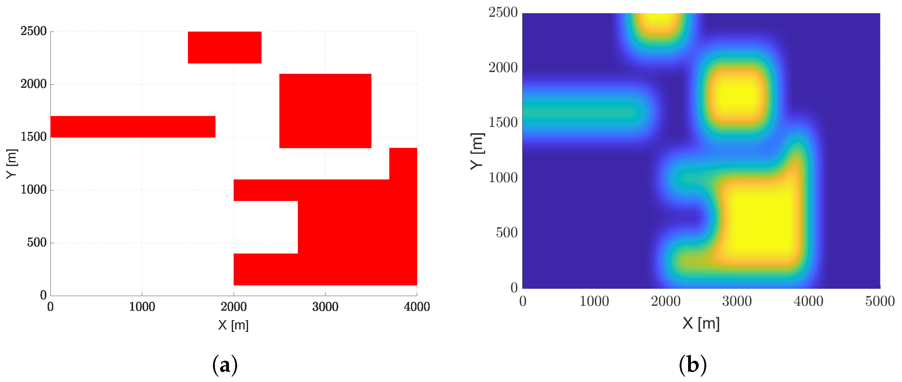
To speed up the exploration process and avoid the computation of the distances from the obstacles at each step, an image-based solution has been adopted. In particular, a binary representation of the scenario is considered, where the zones occupied by obstacles are marked with ones and the free spaces with zeros. Then, a convolutional filter is applied to obtain a blurred image, as shown in
Figure 3b, where the color scale represents the considered exploration distance
. The blue areas indicate low-resolution zones because they are far from the obstacles, while the green ones stand for high-resolution regions because they are close to the obstacles.
To further reduce the computational time, given a node
, a vision cone
of angle
is adopted to limit exploration only to the nodes
falling within
, with an exploration distance
. Denote with
the set of neighbors
in the free space, within the vision cone
, with a distance
from
:
where
indicates the Euclidean norm.
The procedure to find the path between the starting point A and the target point B is the following.
Procedure 3. Theta* exploration process to find the flyable path between two points A and B, with assigned directions and , respectively.
STEP 0—Consider the set
of explored nodes and the set
of unexplored nodes consisting of tuples
, where
is the considered node,
is the departing direction,
is the parent node, and
is the global cost:
with
the length of the path used to fly between
A and
,
the length of the flyable edge
between
and
, and
the Euclidean distance between
B and
.
Initialize and .
STEP 1—Select and remove from the tuple with minimum global cost. Add the tuple to . If , then terminate the procedure.
STEP 2—Compute the vision cone and build the set . If B is in , add B to the set of neighbors .
STEP 3—For each node , build the flyable paths and .
If
, then two flyable edges are needed to find a trajectory between two points with assigned initial and final directions. In particular, said
an intermediate point, two flyable edges
and
must be computed.
STEP 4—For each node
, compute the two possible global costs associated to
:
where the edge
is feasible if it does not intersect any obstacle.
STEP 5—For each node
assign to
the minimum global cost associated to
and the relative parent node
STEP 6—Consider the tuple . If contains a tuple , if then remove and add to . If does not contain any tuple with , then add to .
STEP 7—Go to STEP 1.
To reconstruct the optimal flyable path between A and B, find the tuple with B in the set and move to its parent node. Iterate the process until the parent node is A.
To preliminarily evaluate the algorithm capability in identifying feasible paths, a simple example is presented in
Figure 4, where the initial point and the target point
A and
B are given, with starting and target directions
and
, respectively. The scenario presents one convex obstacle to be avoided at the center of the environment. In
Figure 4b, the final path avoiding the obstacle is shown, while in
Figure 4a, the blue lines show the arcs explored by the algorithm during the search. The results are summarized in
Table 1.
In
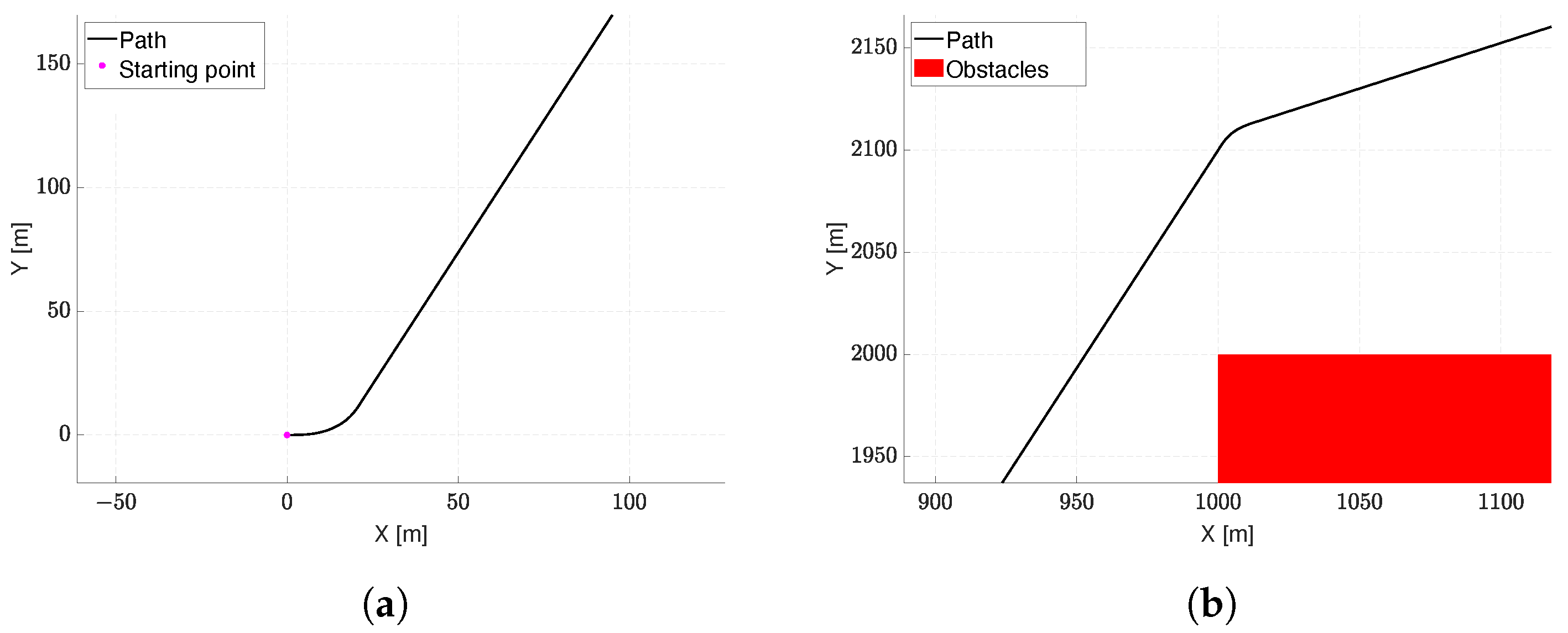
Figure 5, the details of the planned path for this scenario are shown, highlighting the starting turn maneuver, which is needed to deviate from the preassigned initial slope, and the turn needed to go around the obstacle.
4. Results
For a more comprehensive assessment of the algorithm effectiveness, the path planner was tested on five different scenarios. The first test case presents a scenario with several convex and concave obstacles to test the ability of the algorithm to avoid the concavity of obstacles when the vision cone is also in use. In the second test case, the capability of the procedure to use a variable exploration distance is stressed, comparing results with a Theta* without the new feature. The third test case presents a comparison of the results provided by different variants of the algorithm with varying combinations of the proposed features. The fourth test simulates the use of the path planner in a real urban scenario. In particular, a dense area of Napoli (IT) is considered, with the aircraft flying at a fixed flight altitude of m, avoiding buildings. Finally, the last test case is considered to verify the accurate tracking of an aircraft along the planned trajectory.
As shown in
Table 2, the different algorithm variants will be referred to using the following notation:
for the base algorithm implementing only the path transition curve as edges;
for the algorithm with the vision cone option active;
in the case when the variable exploration distance is used;
indicates the algorithm using all the optional features, i.e., the vision cone and the variable exploration distance.
4.1. Test Case #1
This simulation test case evaluates the performance of the proposed algorithm, with and without the vision cone option, in terms of path length and computational burden.
The parameters used in the first scenario are listed in
Table 3. The scenario is composed of four convex and two concave obstacles. To stress the algorithm and prove its effectiveness, the starting point is placed inside the concave obstacle (
Figure 6), and the positions of the obstacles are chosen in order to create narrow passages. The starting and ending directions are arbitrarily chosen.
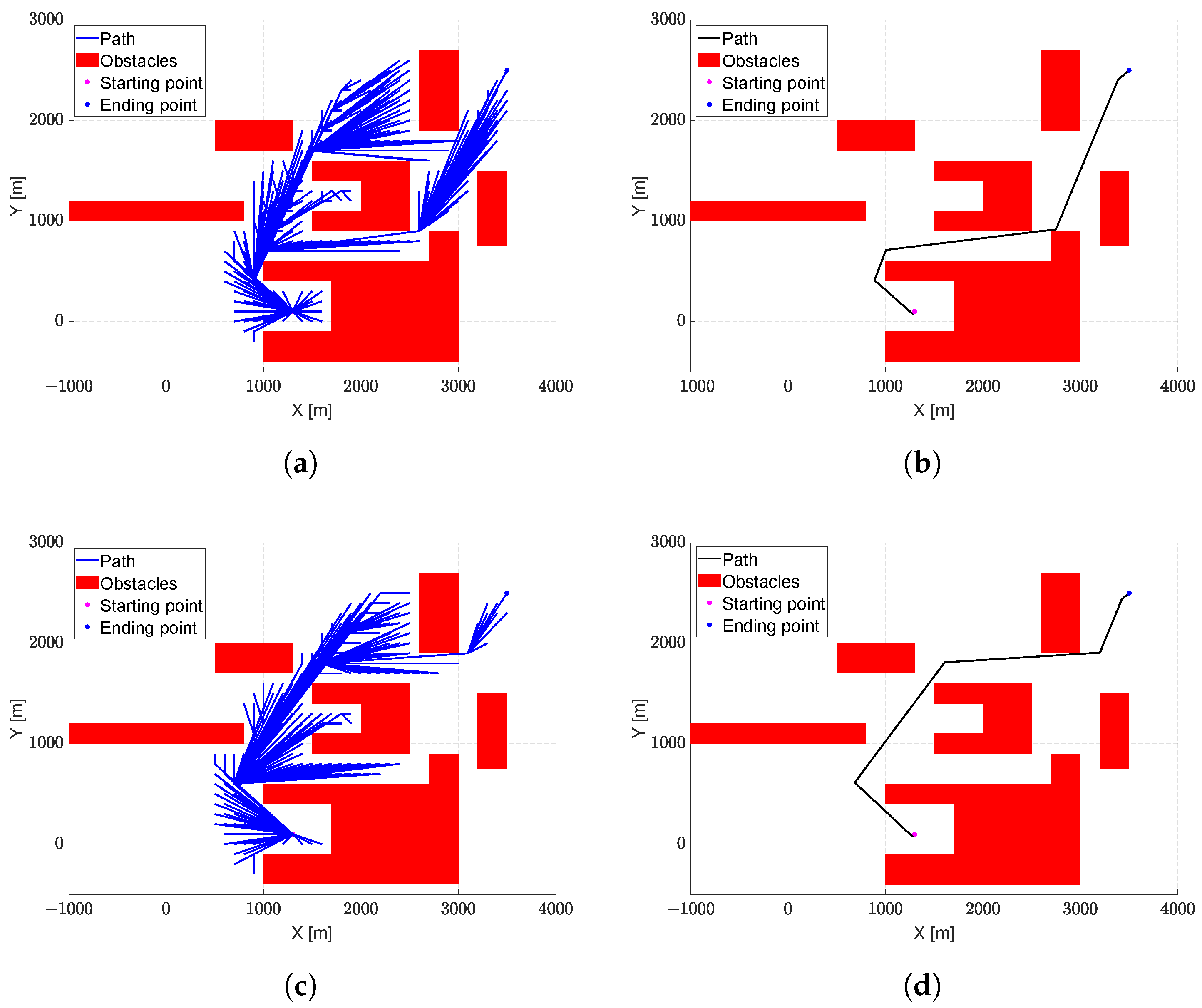
Figure 6 shows the result for the first test case. In particular,
Figure 6a,b represent the explored paths and the final trajectory, respectively, when the vision cone option is not active, while
Figure 6c,d show the results of the algorithm with the vision cone option active.
As can be seen, the aircraft is able to fly effectively in the operational scenarios, passing through narrow passages and avoiding becoming stuck in concave obstacles.
During the exploration phase, the use of the vision cone reduces the number of explored nodes, allowing for a lower number of explored paths, as shown in
Figure 6a,c. In particular, in this case study, the lower number of tested trajectories results in a final trajectory (
Figure 6d) slightly longer than the path obtained without an active vision cone (
Figure 6b), but with the advantage of a reduced computational burden, as highlighted in
Table 4.
4.2. Test Case #2
The main aim of the second test case is to assess the algorithm ability to use variable exploration distance to find the shortest path with a reduced computational burden. The second operational scenario consists of three convex obstacles and one concave obstacle, arranged to form narrow corridors along the path from the starting point to the destination point.
Table 5 lists the parameters used. The obstacles are placed to highlight the different results obtained by using fixed or variable exploration distances. In particular,
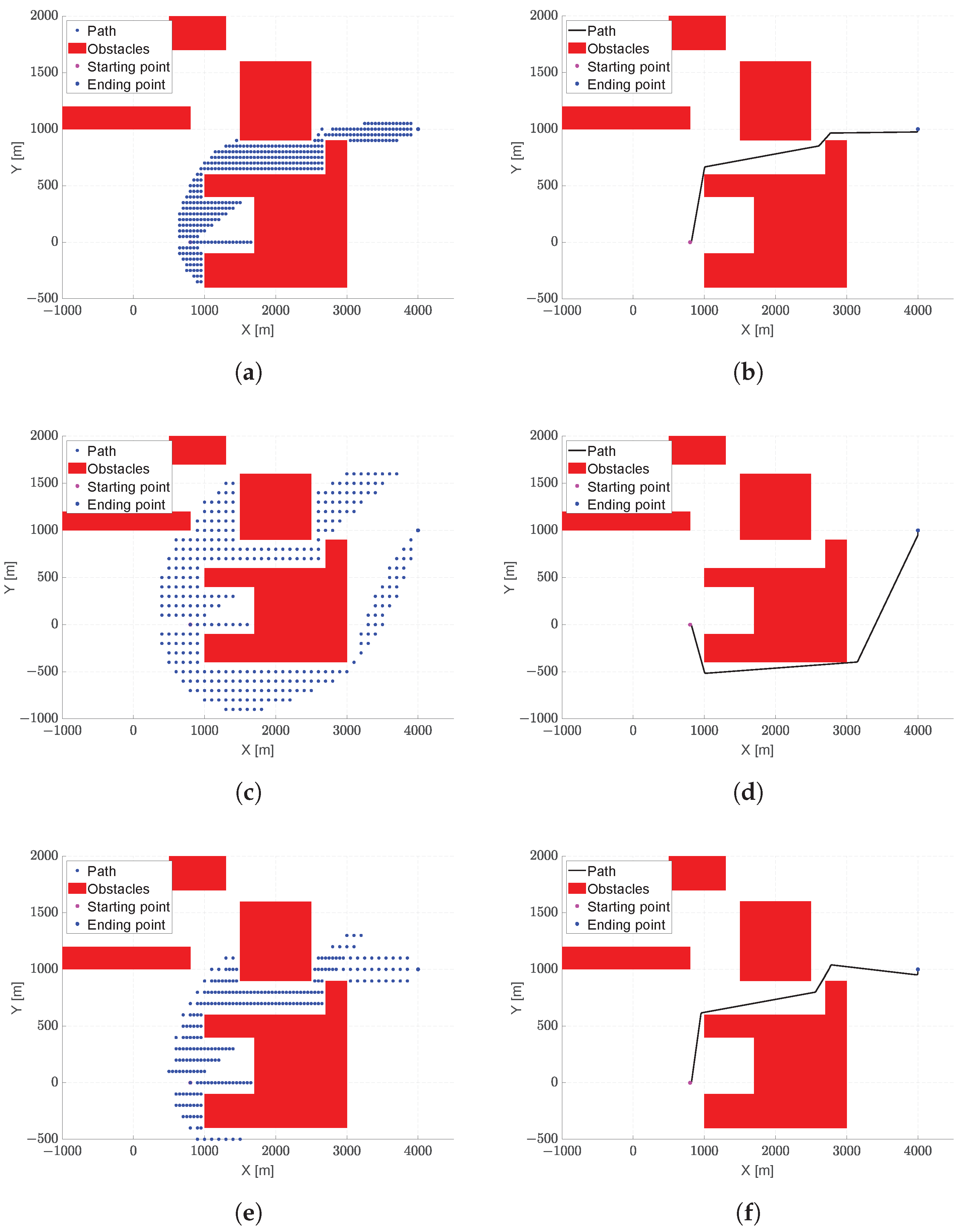
Figure 7a,c represent the explored nodes running the algorithm with fixed exploration distances equal to
m and
m, respectively, while the final paths obtained at the end of these runs are represented in
Figure 7b,d, respectively. In this scenario, having more explored nodes is advantageous in terms of the final trajectory length, as it allows for close passage between obstacles. On the other hand, a lower number of points does not allow for finding a solution of the same quality, as the algorithm avoids the passage through the narrow corridor, leading to a longer trajectory.
A better result can be achieved using a variable exploration distance, as illustrated in
Figure 7e,f. In particular,
Figure 7e demonstrates the benefits of employing the new feature, creating a region with a higher density of nodes only in the neighbors of obstacles. This allows the identification of a final trajectory (
Figure 7f) very similar to the one obtained with more nodes, as shown in
Figure 7b. However, this result is achieved with fewer generated nodes and, consequently, with a lower computational burden.
Table 6 shows the comparison between the proposed algorithms in terms of computational times and trajectory lengths. As can be observed, the algorithm featuring a variable search distance ensures a good solution in terms of final trajectory length with a lower computational burden compared to the other two algorithm variants using a fixed exploration distance.
4.3. Test Case #3
This scenario, consisting of three convex obstacles and one concave obstacle, allows us to test whether the proposed algorithm is able to reduce the computational burden compared to its variants, which use either the vision cone or the variable exploration distance.
The specific arrangement of obstacles forces the algorithms to construct similar paths, allowing us to evaluate the solution goodness in terms of computational burden rather than path length.
The parameters used for this simulation are stated in
Table 7.
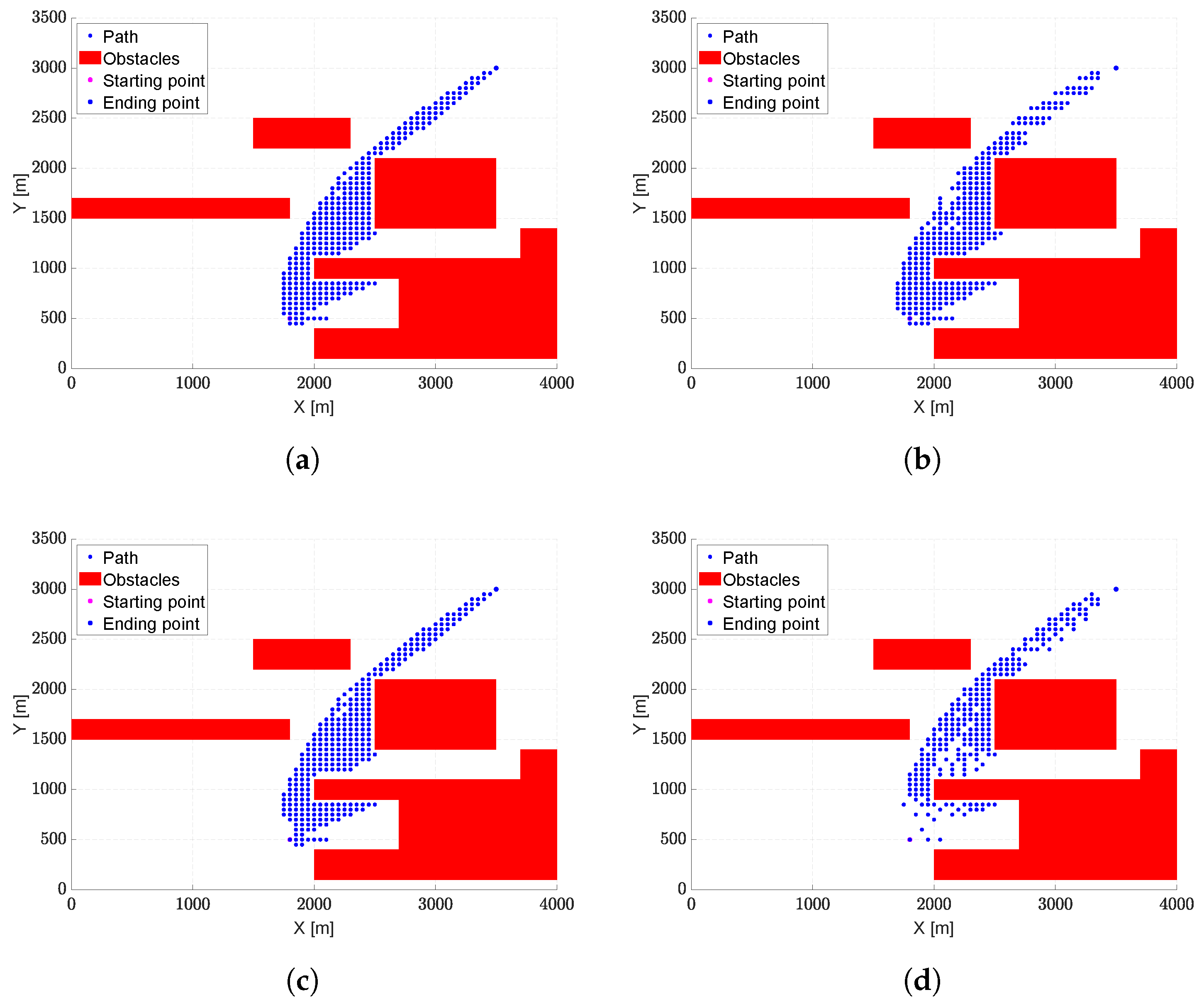
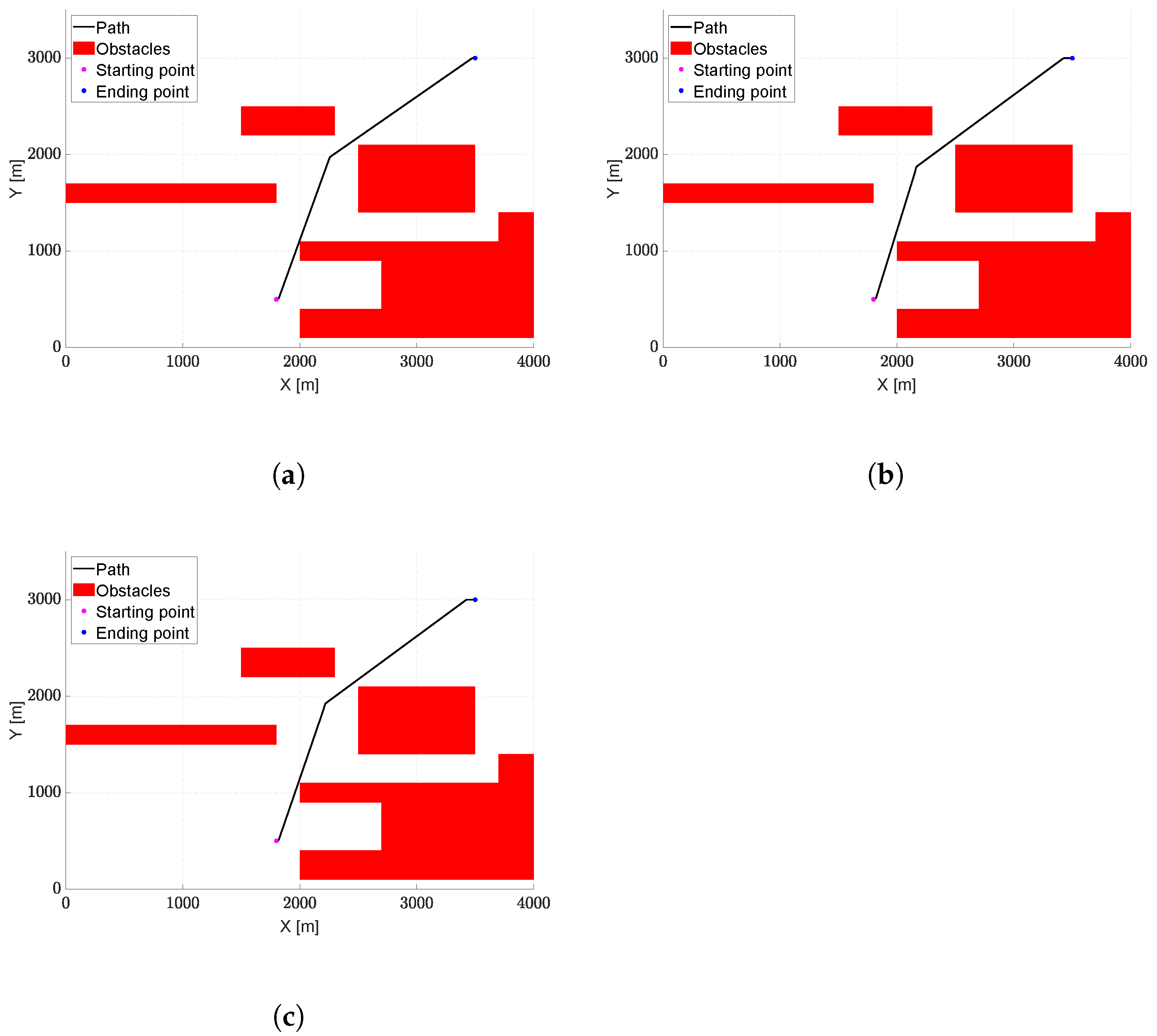
Figure 8 shows the trajectories explored with the algorithms, while
Figure 9 illustrates the final paths, which appear very similar in all the analyzed cases.
Table 8 presents the results in terms of computation time and trajectory lengths. As can be seen, all the algorithm variants are able to identify trajectories of similar lengths. However, the
algorithm, which features both the vision cone and the variable exploration distance, provides not only the shortest trajectory but, above all, shows a significant reduction in the computational time compared to the other algorithm variants.
4.4. Test Case #4: Urban Scenario
The aim of test case #4 is to evaluate the algorithm’s capability of identifying the optimum path in a real urban environment. The parameters used in this scenario are shown in
Table 9. The coordinates are given in terms of longitude and latitude; in particular, this scenario replicates the area of Naples city located between Piazza Nazionale and Centro Direzionale.
The path search is carried out with a fixed exploration distance m. This distance turned out to be a fair compromise between two needs: having a higher number of points to navigate narrow passages and limiting the computational burden even in a scenario full of obstacles.
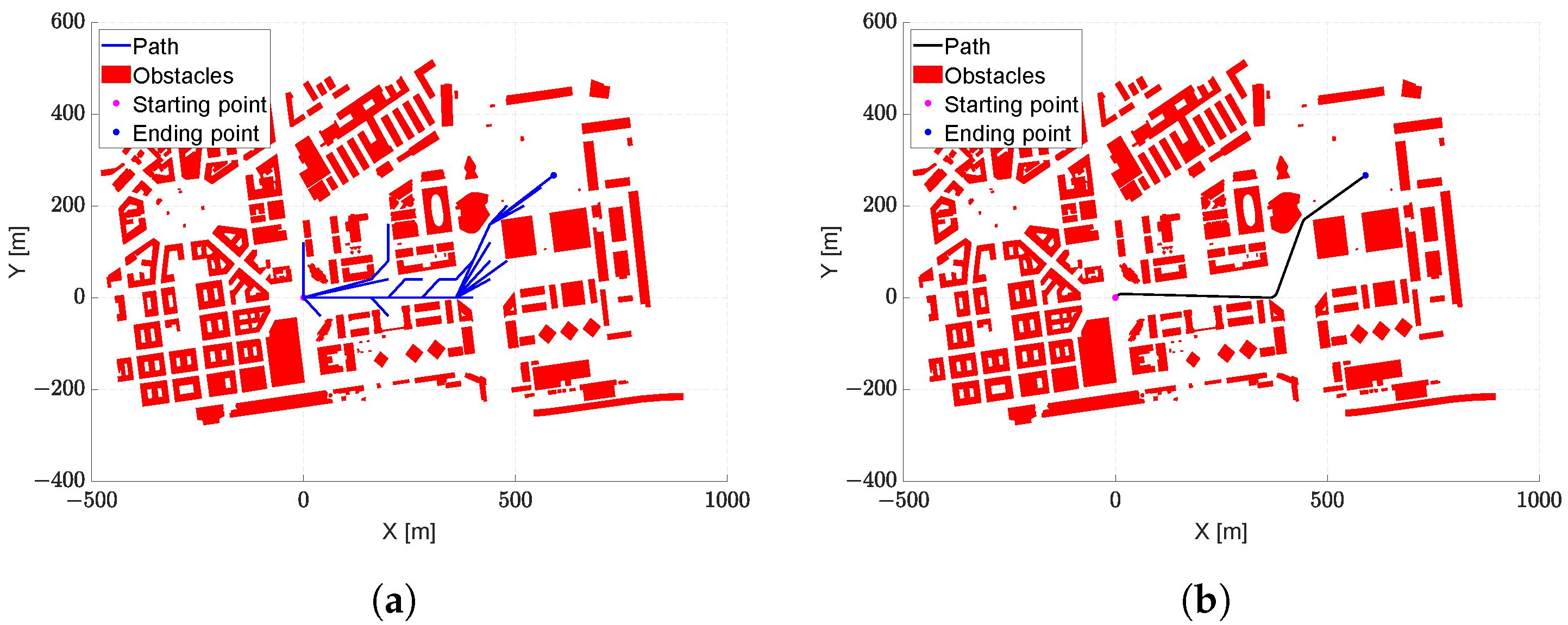
Figure 10 represents the results for this urban scenario.
Figure 10a shows the exploration phase, where the algorithm performs an extensive search of its surroundings to find a feasible path compliant with the UAV’s performance. The final path identified is presented in
Figure 10b.
Table 10 summarizes the obtained results. Due to the large number of obstacles involved in this scenario, the computational burden appears significantly higher compared to the previous test cases. A time reduction could be expected through a pre-processing work aimed at limiting the number of obstacles considered in each iteration, but this goes beyond the scope of this test.
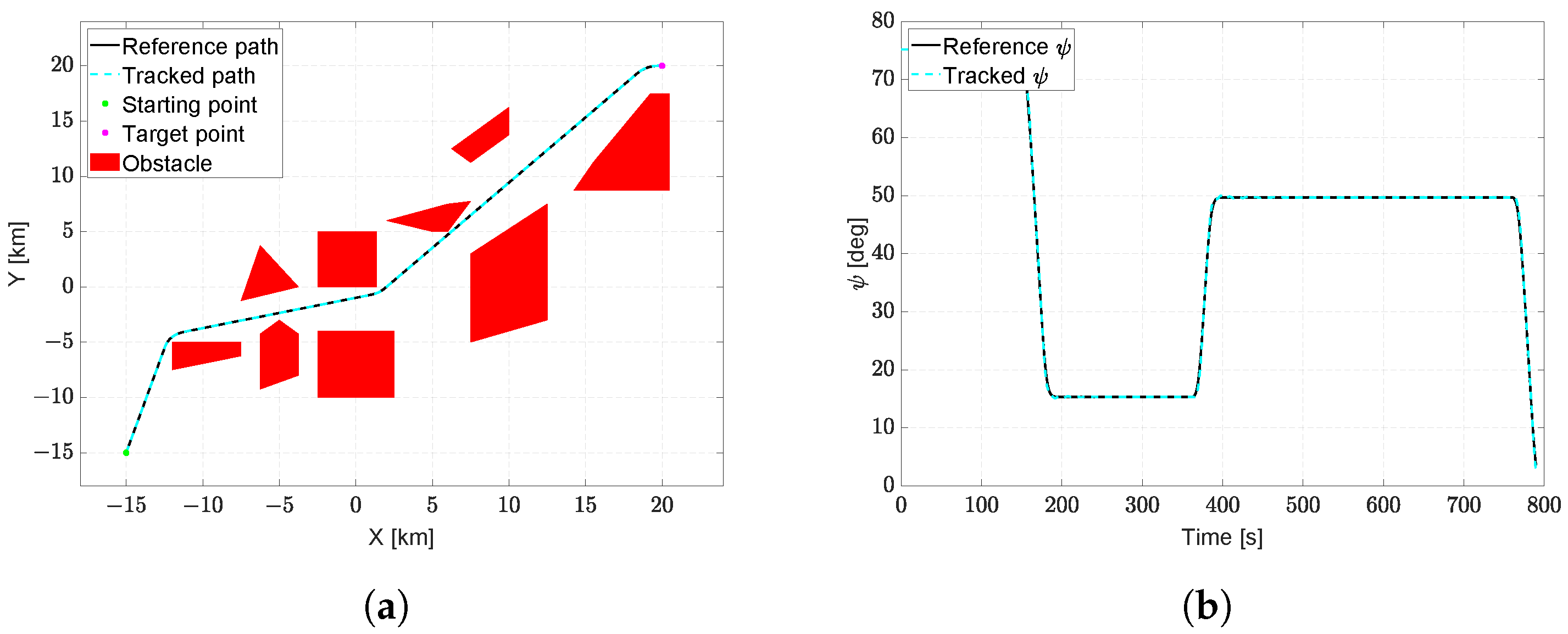
4.5. Test Case #5: Simulation of a Short Cruise Path
In this test case, the problem of planning an optimal path for guiding an aircraft during the cruise phase to avoid specific no-fly zones is considered. The scenario involves two obstacles, a starting point
km, a target point
km, an initial heading
deg, and a final heading
deg. To ensure realism and reproducibility, a general aviation aircraft with characteristics outlined in [
59] was considered for testing. For trajectory tracking, a control system based on classical control methods [
60] was developed.
After planning the optimal path with
, considering
and
, trajectory tracking was simulated to verify its actual feasibility at the cruise speed of
.
Figure 11a displays the planned and tracked path, while
Figure 11b illustrates the desired and actual heading of the aircraft. As observed, the aircraft effectively follows the trajectory, and the only minor discrepancy arises from the sharpness discontinuity, resulting in a jump in the roll angular velocity. Nevertheless, such a model error translates into a tracking error maximum of 7 meters.
5. Discussion
The algorithm’s efficacy was comprehensively evaluated through four distinct scenarios.
In scenarios where the vision cone was active, the algorithm demonstrates a reduction in the number of explored nodes, leading to a more efficient exploration phase. However, such a feature occasionally results in slightly longer trajectories. Furthermore, as highlighted in the first test case, featuring convex and concave obstacles, the algorithm is able to overcome concave structures while using the vision cone. This capability is crucial for scenarios with intricate obstacles where maintaining awareness of the environment is pivotal.
The implementation of the variable exploration distance showcased its advantages, particularly in scenarios with narrow passages. By dynamically adjusting node density, the algorithm achieved optimal trajectories with a reduced computational cost compared to standard implementations. The results were emphasized in the second test case. A comparison with a Theta* employing constant distances demonstrated the algorithm’s superior performance when dynamically adjusting node densities.
Across all scenarios, the algorithm consistently performed well in terms of trajectory lengths. The variant, incorporating both the vision cone and variable exploration distance, emerged as the most efficient in terms of both trajectory length and computational time.
In particular, the third test case also involved a comprehensive comparison of algorithm variants, each incorporating different combinations of optional features. Notably, the use of both vision cone and variable exploration distance features (denoted as ) resulted in better trajectories in terms of overall length with a significant reduction in computational burden. This indicates the synergistic benefits of employing multiple features.
The final test case simulated the algorithm performance in a real urban environment in Naples, Italy. The algorithm successfully navigated a dense urban area, avoiding obstacles and producing feasible trajectories. While the computational burden increased due to the complexity of the scenario, the ability to find suitable trajectories in cluttered environments while managing computational resources is crucial for real-world UAV applications.
To highlight the effectiveness of the proposed methodology in terms of the ability to find the minimum-length path and avoid collisions with environmental obstacles, this section presents a comparison with three algorithms with the same objectives: the Essential Visibility Graph (EVG) with Dubins-based smoothing [
56,
61], a custom graph-based solution with clothoids [
17], and an RRT-based algorithm, named the Stack-RRT* algorithm [
62].
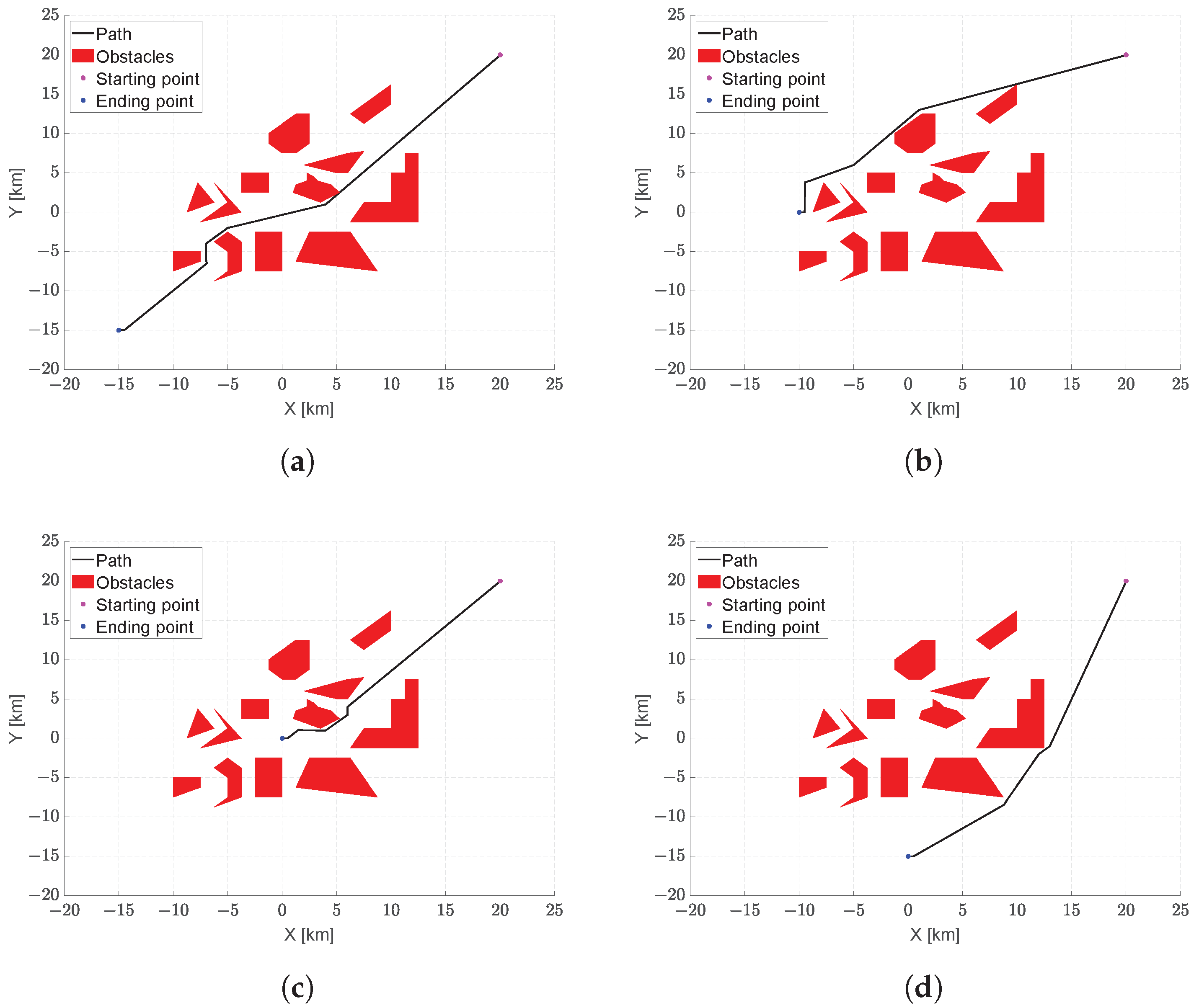
The comparison between the EVG and the proposed algorithm is made by considering four different configurations of the same scenario, whose parameters are summarized in
Table 11. As depicted in
Table 12, the EVG is faster and able to guarantee a proved optimal path in terms of length. However, as shown in
Figure 12, the resulting trajectory is composed of several straight segments, requiring a post-processing smoothing procedure, implemented using Dubins arcs, to make it easily flyable by a fixed-wing aircraft. This approach leads to the presence of discontinuities in curvature
. The proposed
algorithm is able to create a completely flyable path that can be easily followed by the aircraft, with a slight increase in the total length (maximum 1.6%). Regarding the computation time, there is a clear distinction between the processing times required by the proposed algorithm compared to those presented in [
61]. Undoubtedly, the lack of optimization in the code, as well as the implementation in Matlab, has an impact on such extended processing times. The computer considered in this analysis is a laptop with an i5-8250U processor and 8GB of RAM. Certainly, the number of nodes explored in Theta* is much higher than those analyzed in an Essential Visibility Graph. From this perspective, the EVG may appear superior, but in the presence of uncertainty and scenarios involving moving obstacles, Theta* can adapt more easily, even from a procedural standpoint.
The comparison with another clothoid-based approach [
17] is faced using the scenario of the test case #3 (see
Section 4.3). The parameters are summarized in
Table 7. The paths for the comparison are illustrated in
Figure 13, while the results are shown in
Table 13. It is worth noting that, although both models provide easily flyable trajectories for fixed-wing aircraft, the proposed algorithm appears to be more efficient, ensuring a shorter trajectory at a lower computational burden.
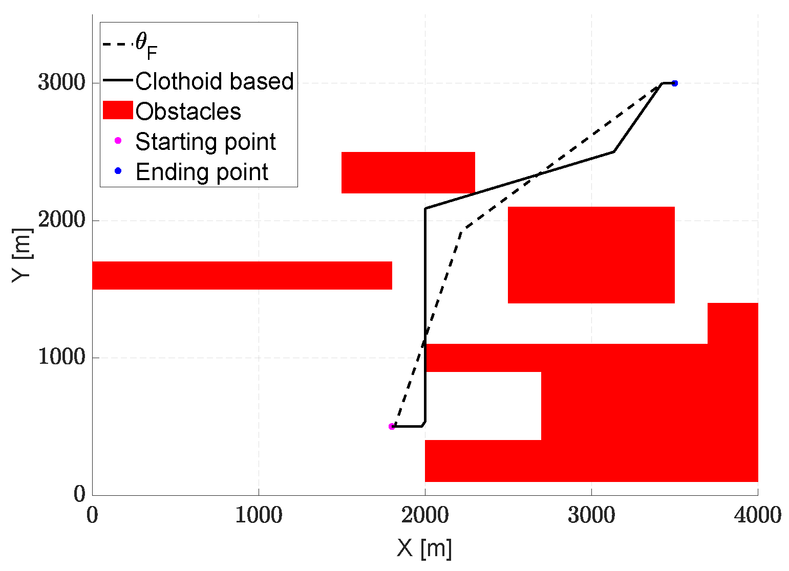
Finally, a comparison with an RRT-based algorithm is presented, considering four different scenarios introduced in [
62]. The results, in terms of generated paths, are depicted in
Figure 14. As shown in the figures,
is capable of planning paths similar to Stack-RRT*, effectively addressing challenges posed by non-convex obstacles. Additionally, as emphasized in
Table 14,
can identify paths with lengths comparable to the outcomes reported in [
62]. Regarding computation times, although they may appear high, it is important to consider both the type of processor available and the lack of code optimization.
6. Conclusions
In this paper, a path-planning strategy for fixed-wing UAVs is proposed by enhancing the so-called Theta* algorithm. The path design involves a piece-wise curve composed of circular and spiral arcs, ensuring compliance with aircraft performance constraints. In particular, the transition between the initial and the target directions is made by means of Euler spiral-based transition curves, comprising two spirals and one circular arc having a curvature compliant with the specific aircraft characteristics.
The optimization of the final path is based on an enhanced version of the Theta* algorithm, where arcs between nodes are defined by the aforementioned path transition curves. This solution is able to generate trajectories without discontinuities, ensuring that the entire flight path is compliant with the performance of the aircraft. To reduce the algorithm’s burden on the CPU, the computational grid of Theta* is dynamically generated with a variable step size, taking into account actual distances to obstacles. The exploration of the search space is further enhanced by the introduction of a vision cone, limiting the algorithm exploration only to relevant areas and preventing unnecessary maneuvers.
The results of comprehensive tests on five distinct scenarios demonstrate the effectiveness of the proposed algorithm. The first test, involving scenarios with both convex and concave obstacles, highlights the capability of the algorithm to find feasible paths in complex environments, also with the use of the vision cone feature, which is mainly aimed at reducing computational time. The second test emphasizes the advantages of adopting a variable exploration distance, showing its superiority over a standard Theta* algorithm. In the third test, a comparative analysis between the algorithm variants, incorporating all the developed features, demonstrates the robustness of the proposed approach. The fourth test simulates a real urban scenario in Naples, Italy, where the UAV, flying at a fixed altitude, successfully avoids buildings while reaching the destination point. Finally, the last test case verifies the accurate tracking along the planned trajectory using a high-fidelity simulator.
In summary, the results show that the proposed path-planning procedure allows the aircraft to effectively navigate through narrow passages and avoid concave obstacles. During the exploration phase, the use of a vision cone significantly reduces the number of nodes explored, resulting in a slightly longer final trajectory but improving computational efficiency.
Furthermore, the adoption of a variable exploration distance, creating a region of higher node density only in the proximity of obstacles, improves the algorithm’s effectiveness by achieving a final path similar to a trajectory obtained with a denser presence of nodes but with a reduced computational burden.
Further improvement opportunities exist, especially in scenarios with a high number of obstacles. Exploring pre-processing techniques to limit obstacles considered in each iteration could potentially enhance computational efficiency. Furthermore, additional refinements and applications can be explored, considering 3D scenarios and the use of path transition curves including climb maneuvers.
