Article

Air Route Design of Multi-Rotor UAVs for Urban Air Mobility

1
College of Civil Aviation, Nanjing University of Aeronautics and Astronautics, Nanjing 210016, China
2
School of Transportation, Southeast University, Nanjing 211189, China
3
College of Mathematics, Nanjing University of Aeronautics and Astronautics, Nanjing 210016, China
*
Author to whom correspondence should be addressed.
These authors contributed equally to this work.
Drones 2024, 8(10), 601; https://doi.org/10.3390/drones8100601
Submission received: 23 August 2024 / Revised: 15 October 2024 / Accepted: 16 October 2024 / Published: 18 October 2024

Abstract

:
UAVs will present significant air traffic in the urban airspace in the future, which brings new challenges to urban air traffic management and control. This paper presents an air route design scheme for multi-rotor UAVs in urban airspace to enable UAV operations at orderly levels. The air routes include legs and intersections, which are the three-dimensional channels of UAV flight. Based on the concept of structured and layered urban airspace, the cylindrical pipeline flight leg is designed, and the operation concept, characteristic parameters and flight procedures of along-road and roundabout intersections are proposed. By defining UAV conflict risk and intersection service level metrics, the operation situation of UAVs is quantitatively evaluated. Taking an urban transportation scenario as a case, the proposed route design scheme is simulated in different scale UAV operating scenarios. The results show that the number of UAVs at the intersection is positively correlated with the conflict probability, the number of crossing routes is negatively correlated with the intersection passing rate, and the UAV arrival rate is positively correlated with the intersection average passing time. The along-road type intersection is suitable for the area with fewer crossing routes and sparse UAVs, while the roundabout type intersection is adapted for the area with more crossing routes and dense UAVs. This research provides a new idea for urban UAV air route design, which is helpful in promoting the standardized management of UAVs and accelerating the integration of UAVs into urban airspace.

1. Introduction

With accelerating urbanization, increasing ground traffic congestion and limited underground space development, expanding low-altitude resources and urban air mobility (UAM) has become a hot issue of common concern in the world. UAM is a brand new three-dimensional transportation system based on vertical take-off and landing, point-to-point transportation, which is suitable for intercity and intra-city rapid transportation [1]. In recent years, Airbus, Uber, EHang and other companies have laid out the new ecology of the UAM industry, and its development has ushered in new opportunities. According to Morgan Stanley and Roland Berger institutions, the global UAM industry can reach USD 1.5 trillion in 2040, and 98,000 flying cars will be put into use in 95 major cities worldwide in 2050.
UAVs are flexible, free, and can easily respond to users’ point-to-point transportation demands with only a small take-off and landing site, thus becoming the main carrier for UAM [2]. With the iterative update of 5G communication and Internet of Things (IoT) technologies, the market for UAV services continues to expand, such as applications in logistics delivery distribution, sightseeing tourism, and security inspection [3]. The rapid development of the UAV industry has also put forward new demands on UAS (UAV system) safety. With complex urban airspace, dense buildings, different UAV forms and diverse tasks, how to ensure the standardized and orderly operation of UAVs has become a pressing problem to be solved [4]. Figure 1 shows the schematic diagram of UAV operation, and arrows with different colors represent the flight directions of UAVs at different altitudes. If the UAV is in free airspace, it is less constrained at this time, and the UAV performs its respective tasks according to the established requirements. However, with the expansion of the UAV operation scale, due to the lack of route constraints and guidance, the air flight order tends to be chaotic, and conflicts and even collisions between UAVs are very likely to occur, seriously threatening the safety of people’s lives and property on the ground. Facing the complex flight situation in future urban airspace, free airspace can no longer fully adapt to the operational requirements of high-density UAVs. Therefore, it is necessary to reasonably configure the air route as a medium for UAV flights to ensure the smooth operation of UAVs.
Urban air route belongs to a special airspace, which is a corridor with transportation functions, and its structure is influenced by coupling multiple factors such as building architecture, population density, and UAV performance [5]. Air route design can be divided into two categories in terms of the degree of planning: macro-route planning and micro-configuration design. Macro-route planning focuses on the overall structure design, aiming at planning collision avoidance routes that satisfy constraints between UAV take-off and landing nodes, which can be regarded as a path search problem in irregular three-dimensional space of airspace [6,7]. The current algorithms for path search are mature, and the common methods include a graph search method and a heuristic algorithm [8,9]. Based on the known airspace environment and obstacle information, the graph search algorithm finds the optimal path by depth-first or breadth-first search. Dijkstra’s algorithm is the classical single-source shortest path search algorithm, on which the heuristic cost function is introduced to form the A* algorithm [10,11]. Zhang et al. introduced the bidirectional search strategy, adopted the improved A* algorithm to plan urban logistics UAV paths, and utilized the B-spline method for path smoothing optimization [12]. Through the comprehensive evaluation of urban and customer service benefits, Shao et al. proposed an A*-based UAV path planning algorithm that can effectively reduce the risk and cost of UAV operations [13]. Heuristic algorithms perform path planning by simulating the behavior of biological groups in natural ecosystems, mainly including genetic algorithms, particle swarm optimization, immune algorithms [14,15,16], etc. Dai et al. designed a Min–Max energy path planning model considering the mountain obstacles blocking UAV sensor limitations and used a genetic algorithm to solve it [17]. Patley et al. adopted the tilted plane strategy to obtain three-dimensional waypoints and proposed an improved particle swarm algorithm based on orthogonal design, which effectively shortens the convergence time while planning the optimal UAV 3D path [18]. The micro-configuration design focuses on the study of the three-dimensional air route space shape, aiming to adapt to the smooth flight of UAV by setting appropriate air route profile shape and structural parameters. The research on configuration design is still in the initial stage. Gharibi et al. preliminarily defined the route structure and proposed the concepts of route, intersection, and node [19]. Xu et al. designed the cylindrical pipeline route and positioned the three-dimensional spatial characteristics of the route by setting parameters such as starting point, ending point, course angle, and route width and height [20]. Quan et al. designed a cubic sky highway with the corresponding intersection configuration for the dense traffic environment in airspace, set isolation strip within the airway to alleviate the conflict between the carriageways, and verified the effectiveness of setting sky highway through UAV simulation flight [21]. In order to comply with the heterogeneous UAV operation requirements, Jang et al. designed three multi-channel airspace concepts with reference to ground roads, including sky lane, sky tube and sky corridor, each with different degrees of freedom to guide and constrain UAV flight [22]. Accordingly, Lowry proposed a novel spiral air elevator concept that can effectively reduce the volume of airspace occupied by climbing and descending aircraft, increasing the capacity of urban airspace [23].
The current research in the related field mainly focuses on proposing the concept and configuration design scheme of a new urban UAV route, which meets the needs of large-scale UAV operation and provides a certain theoretical basis for urban air traffic management. However, the construction of the UAV route is in the rising stage, and the operation rules are not yet perfect. The existing research focuses on the macro network topology planning, and most of the specific configuration design stays in the conceptual design stage, with less consideration given to the specific operation requirements of each stage of UAV flight. In addition, a UAV’s turning and obstacle avoidance at the multi-route intersection depends on autonomous control and lacks normative and interactive guidance. Therefore, how to combine the urban environment with the characteristics of UAVs to design the route and formulate the corresponding flight rules to ensure its safety and efficiency has become the key issue of UAV control. In order to regulate the operation and management of UAVs in urban complex airspace, considering the airspace structure and UAV performance, this paper proposes a route configuration design method for multi-rotor UAVs. The main contributions of this paper are listed as follows:
(1)
The three-dimensional configuration of the UAV is simplified by constructing a UAV-protected zone, and the design concept of flight leg and intersection is proposed based on layered airspace. Two types of intersections, along-road and roundabout, are proposed, their characteristic parameters are defined in detail, and flight procedures such as flying into, turning, lifting and flying out are designed, which provides a complete specification system for route operation.
(2)
The UAV conflict risk and intersection service level metrics are defined respectively from two aspects of safety and efficiency. For two-road, three-road, and four-road intersections, the UAV operation situation of along-road and roundabout intersections is quantitatively analyzed through simulation experiments, and the performance characteristics and applicable scenarios of various types of intersections are analyzed, which provides a reference for optimizing the route network topology and traffic flow configuration.
The remainder of this paper is organized as follows. In Section 2, the basic concept and operation mode of the air route are presented. The UAV leg configuration and two intersection design modes are introduced in Section 3. In Section 4, the structure parameters and flight procedures of along-road and roundabout intersections are designed, respectively. In Section 5, the operation evaluation metrics are proposed, followed by the route simulation results and performance analysis in Section 6. The conclusions are provided in Section 7.

2. Problem Statement

In order to clearly understand the concept and operation characteristics of the UAV route, this section first introduces the route attributes and design principles. Since the air route operation is greatly affected by the airspace structure, the layered operation mode is further proposed by selecting the optimal urban airspace structure. Due to the variable altitude of UAV during maneuvering operation on the route, a protected zone model is constructed to simplify the characterization of its motion behavior and lay the foundation for subsequent route design and evaluation.

2.1. Concept of UAV Route

The UAV route is a corridor with a three-dimensional spatial structure. It usually has definite characteristic attributes, such as length, height, profile and course angle. The route is also the medium for the UAV to perform transportation tasks, and a reasonable route configuration is essential to ensure smooth operation. UAV route design usually follows the following principles:
(1)
Security. Security is the lifeline of urban airspace. Flying along routes at low-altitude in the city, UAVs need to avoid space entities such as buildings and trees. At the same time, UAVs should also be kept at a safety separation from other UAVs to avoid collisions.
(2)
Publicity. Air routes serve the public and should be able to meet the demands of various UAV operation scenarios, such as logistics, tourism and daily commuting.
(3)
Flexibility. In the urban low-altitude airspace, there are unexpected events such as equipment failure and bad weather. It is necessary to pay timely attention to the changes in the internal and external environment of the UAV, adjust the air route as required, and coordinate the orderly flight of the UAV.
(4)
Economy. Under the premise of satisfying safety, the demands of multiple stakeholders should be taken into consideration as much as possible to obtain the best benefits with less investment and make the limited airspace resources more effective.
In the process of route design, there are usually three concepts that are easily confused, namely, airline, track, and leg. In order to facilitate the understanding of the latter, the following concepts are defined.
(1)
Airline. The given route was developed in the flight plan before the UAV mission with temporal and spatial certainty.
(2)
Track. The actual flight trajectory of the UAV has spatial and temporal uncertainty due to the influence of random factors such as weather and navigation.
(3)
Leg. As a route component, a leg is defined as a section between two nodes, and a route may contain more than one leg.

2.2. Operational Modes

As a special airspace, air route configuration is affected by the structure of urban airspace. Common airspace structures include full mix, layers, zones, and tubes. By studying the effects of airspace structure on urban airspace safety [24], capacity [25], and noise [26], it is shown that layers are currently the best urban airspace structure. Within the layers, the airspace is discretized into multiple horizontal altitude layers, and UAVs generally do not involve altitude changes when flying along the route.
The urban airspace contains multiple route altitude levels, and the altitude level spacing meets the minimum vertical safety separation of UAVs. Based on the direction due north of the local longitude, the routes are divided into eastward routes and westward routes according to the course angle. The course angle is the angle between the route direction centerline and the local longitude line, which is used for route orientation. Eastward 0°~180° (excluding 180°) is the eastward route, and eastward 180°~360° (excluding 360°) is the westward route. Each altitude level follows a unidirectional operation mode and adjacent altitude levels operate in opposite directions. By setting a vertical route, the connection between adjacent altitude layers can be realized so that the UAV can fly back and forth. The UAV takes off from the vertiport at the departure node, climbs to the specified altitude, enters the route, and begins to carry out the transportation task along the established airline according to the flight plan. When the UAV flies horizontally in the route, it can change the altitude layer by executing the lifting procedure at the intersection node to change the flight course. When the UAV reaches the airspace near the destination, it lands at the vertiport to complete the task.

2.3. Protected Zone Model

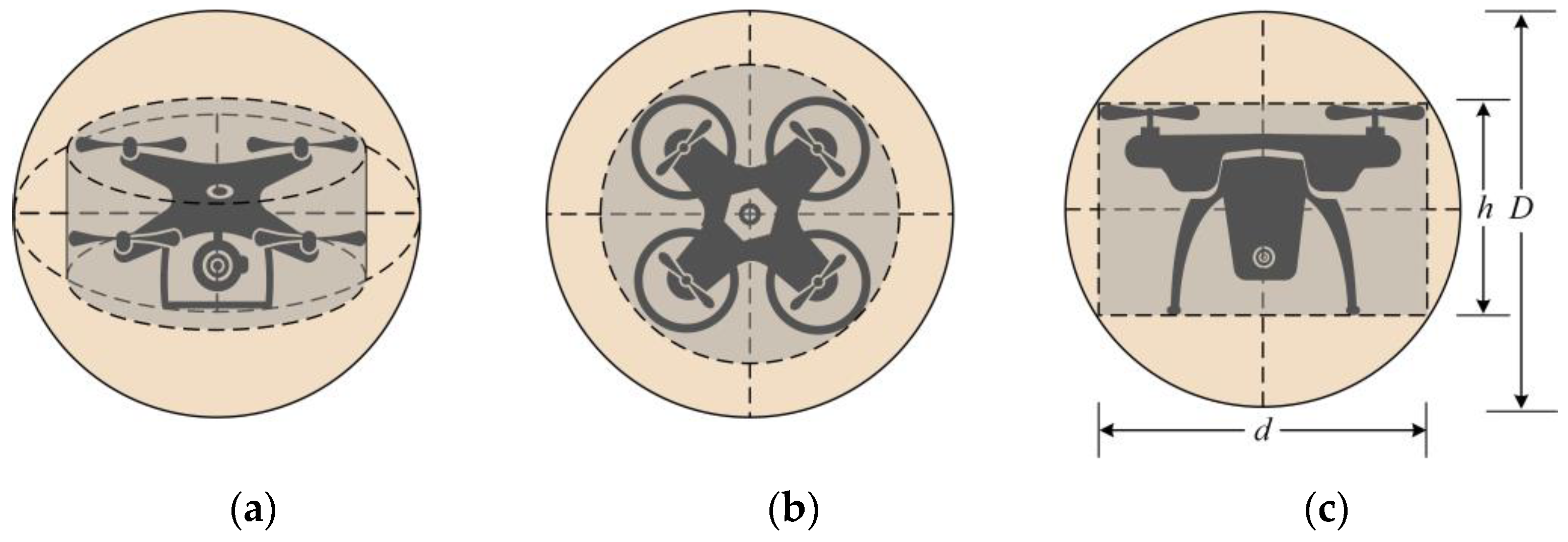
Since the route configuration is affected by the UAV body structure, the UAV can no longer be regarded as a particle, and its three-dimensional spatial structure needs to be considered when conducting route design. The common type of urban UAV is a multi-rotor UAV, which has excellent performance in vertical take-off and landing, fixed-point hovering, and can respond to users’ point-to-point transportation needs only on a small site. This section takes multi-rotor UAVs as an example of how to design the protected zone. The UAV-protected zone is the physical space containing a certain area around the UAV as the center, which is used to simplify the behavior modeling of irregular configuration UAVs. It is often based on simple geometry, such as cube, cylinder, sphere, etc. The classical cuboid protected zone is the Reich model, which is adopted to quantitatively estimate the vertical, longitudinal and lateral collision risk of parallel routes in the North Atlantic [27]. On this basis, Peter Brooker proposed the post-Reich model, also known as the Event model, for the lateral collision risk of aircraft [28]. Since traditional civil aircraft need to maintain minimum safety separations in vertical and horizontal directions, cylinders are widely used in conflict probability estimation. When the UAV is rolling or pitching, considering that the cube and cylinder cannot accommodate the UAV well [29], the minimum external sphere of the UAV body cylinder is adopted as the UAV-protected zone, as shown in Figure 2. No matter how the UAV altitude changes, the UAV is always in the spherical protected zone. When any two UAV-protected zones intersect, a potential UAV conflict is considered to occur.
The size of the protected zone depends on the technical parameters of the UAV. If the maximum horizontal size of the UAV (usually taken as the wheelbase) is d , and the height of the UAV is h , then the diameter of the sphere-protected zone D can be calculated as:
D = d 2 + h 2

3. Air Route Design

The route structure directly affects the operation of UAVs, and the appropriate route design is helpful to ensure orderly flight. Based on the characteristics of the UAV-protected zone, this section designs the UAV leg configuration and proposes two route intersection design patterns, including along-road and roundabout intersections.

3.1. Leg

From the macroscopic point of view, the leg is similar to the ground section, which refers to the traffic line between two adjacent nodes in the route network. Nodes usually refer to intersections, reachable nodes of interest, etc. The alternating connection of flight legs and nodes constitutes the UAV flight route. From the microscopic point of view, the leg is an air corridor with a three-dimensional spatial configuration. Based on the UAV spherical protected zone, a cylindrical pipeline flight leg is designed, as shown in Figure 3. The leg is a single lane and can only accommodate one UAV in the same direction. Considering the flight error due to altitude change and navigation and positioning, a buffer zone is set on the basis of fully accommodating the UAV-protected zone.
where b is the buffer length. Within a single leg, the UAV flies along the centerline and remains within the leg boundary when it is slightly disturbed [30].

3.2. Intersection

The intersection of two or more routes constitutes the intersection, which is a key hub for UAV convergence, turning and evacuation. The connectivity between vertiports on the ground can be achieved through the orderly articulation of routes and intersections [19]. Due to the different speed directions of UAVs entering and leaving the intersection, there is mutual interference in space and time, which leads to potential conflicts between UAVs. Therefore, the intersection is the key node of the network, and its passage quality directly affects the transport safety and efficiency of network transportation. The type of intersection reflects the form of route confluence, and its typical types include X-shaped, Y-shaped, and multi-way intersections. The intersection of two routes constitutes an X-shaped intersection, and the intersection of more than two routes constitutes a multi-way intersection. The intersection form can be transformed by adjusting the angle of intersecting routes. If the two routes converge into one route after intersecting, a Y-shaped intersection is formed, where the UAV can merge and diverge.
When multiple UAVs fly in airspace, their flight tracks may cross, and there is a risk of conflict. If the UAVs are in free airspace, the traffic flow tends to be chaotic as the number of UAVs increases, and the risk of conflict increases. Therefore, by establishing intersections to guide UAVs to form an orderly traffic flow, airspace operation safety can be effectively improved. In this section, two configurations of intersections, along-road and roundabout types, are proposed on the basis of free flight of UAVs, as shown in Figure 4, in which the arrows indicate the flight directions of UAVs. The along-road intersection is similar to the ordinary fork on the road; the UAV flies along the route and changes the heading through the intersection. The roundabout intersection is similar to the ground circular intersection, and the UAV enters the traffic circle, flies clockwise or counterclockwise along the circular route, and exits the roundabout when it reaches the target route. In Section 4, the operation concept, structural parameters, and flight procedures of the two intersections are introduced in detail.

4. Intersection Model

4.1. Along-Road Type

4.1.1. Operation Concept

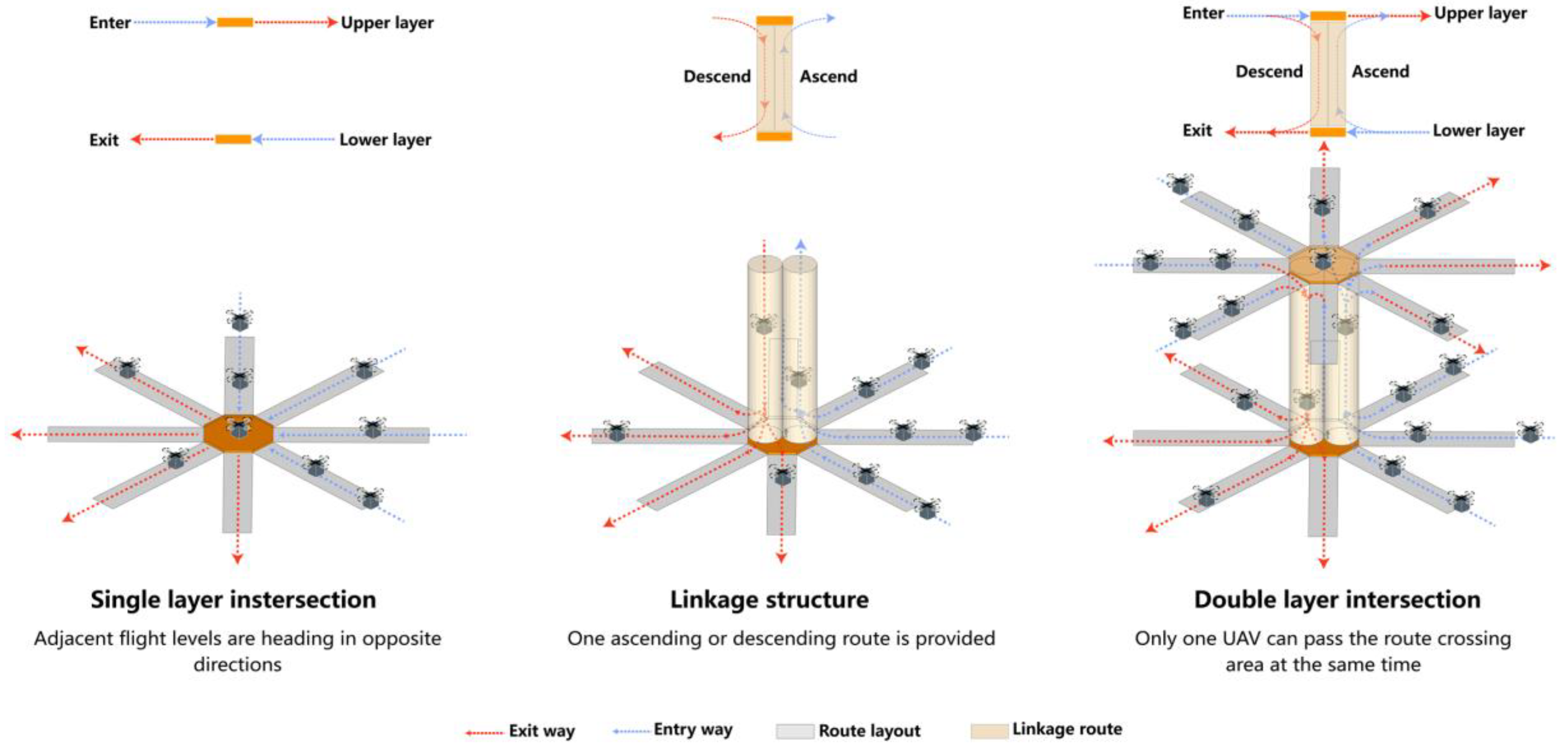
The along-road type intersection is a kind of intersection designed in the urban air traffic network based on the convergence form of routes, with specific geometry and traffic organization. The UAV conducts steering operations in the route-crossing area. Considering the influence of obstacles, special weather, temporary activities and other factors, the UAV may need to change the flight altitude to adjust the course during the execution of the mission. To regulate UAV lift operations, two elevators are set up in the route-crossing area to connect the two adjacent flight levels, which are shared by UAVs that need to change altitude to perform ascending or descending maneuvers, as shown in Figure 5. Due to the separation of the eastward and westward routes, the elevators follow independent one-way driving rules; that is, each elevator is only available for the ascent or descent of UAVs. The blue dotted lines represent the inbound/ascending routes, and the red dotted lines represent the outbound/descending routes, thus realizing the two-way diversion between ascent and descent, which can effectively avoid the UAV head-to-head conflict.

4.1.2. Characteristic Parameters

(1)
Route-crossing area
The route-crossing area refers to the area at the intersection where routes in different directions interchange with each other, involving multiple types of traffic demand such as straight, left and right turns. As a typical form of intersection, two-road intersection is the basis of three-road and multi-road intersection. We take the two-road intersection as an example to design the parameters. When the UAV turns, the fuselage tilts into a rolling position, and the lift generated by the rotors balances the centrifugal force and gravity. Then, the force balance equation of UAV is expressed as:
F sin ϕ = M v 2 r F cos ϕ = M g
where F is the rotor lift; ϕ denotes the UAV rolling angle; M is the UAV mass; v represents the flight velocity; r indicates the turning radius; g is the acceleration of gravity.
Then the minimum turning radius r min can be derived as:
r min = v 2 g tan ϕ max
where ϕ max is the maximum rolling angle of the UAV.
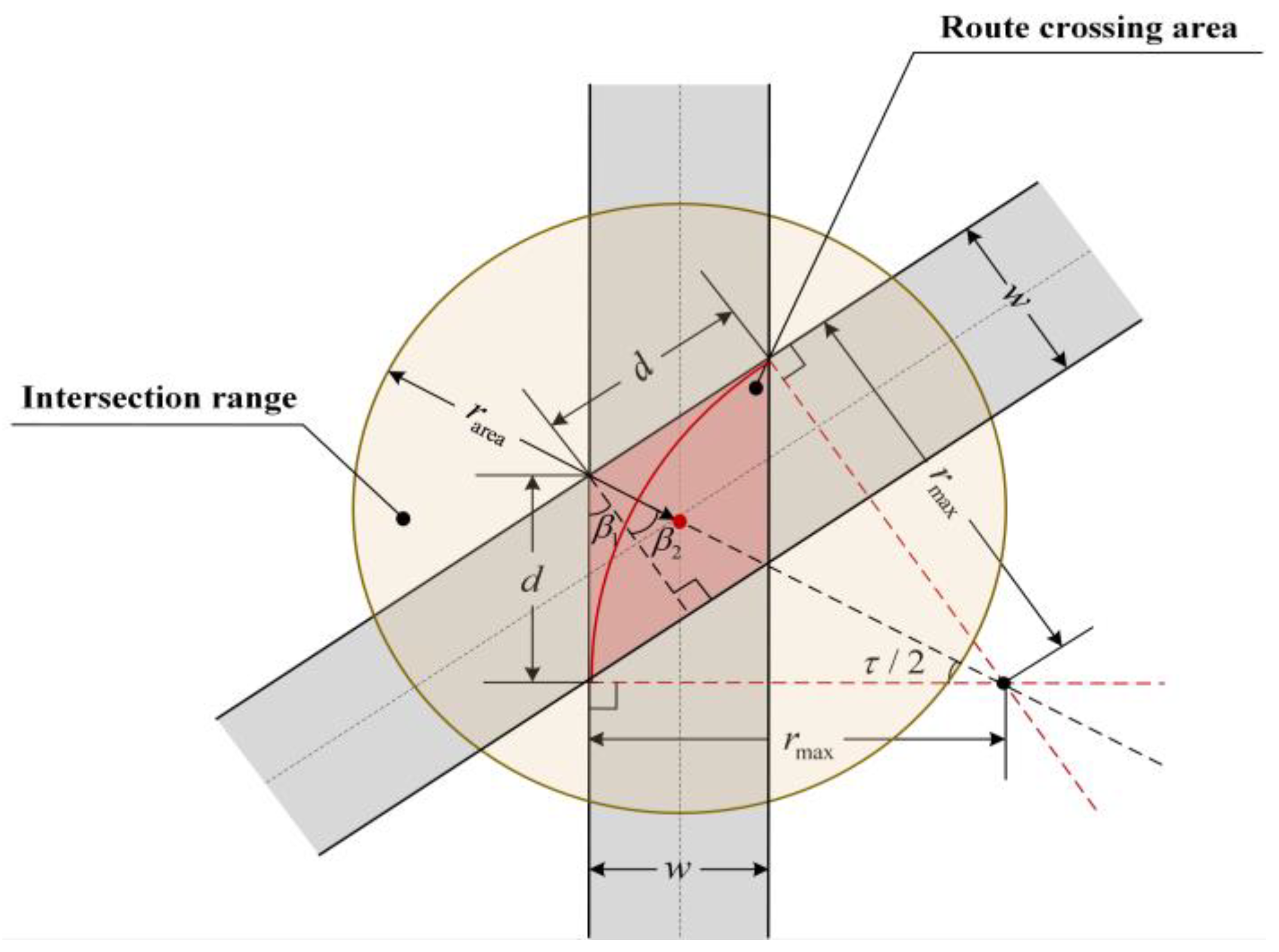
Setting the UAV to perform turn operations only in the route-crossing area, there is a maximum turning radius. If the course angles of the two routes are α 1 and α 2 respectively, then the included angle τ = α 1 α 2 , and the auxiliary angles β 1 , β 2 are defined as shown in Figure 6. The intersection range is defined as a circle with the center of the route-crossing area as the center and the radius as r a r e a .
The route width is w , and the length of the route-crossing section d is calculated as:
d = w cos β 1 = w cos ( π 2 τ ) = w sin τ
The maximum turning radius r max is displayed as:
r max = d tan ( β 1 + β 2 ) = d tan ( π 2 τ 2 ) = w 1 cos τ
Therefore, the turning radius of the route needs to satisfy the following constraint:
r min < r < r max
At any time t n , the state value S t a t u s i t n of the intersection is represented by a binary variable as:
S t a t u s t n = 0 , Available 1 , Occupied
where S t a t u s i t n = 0 indicates that there are no UAVs in the route-crossing area; S t a t u s i t n = 1 means that the presence of a passing UAV in the route-crossing area or the presence of a UAV ready to fly into or out of the elevator.
(2)
Elevator
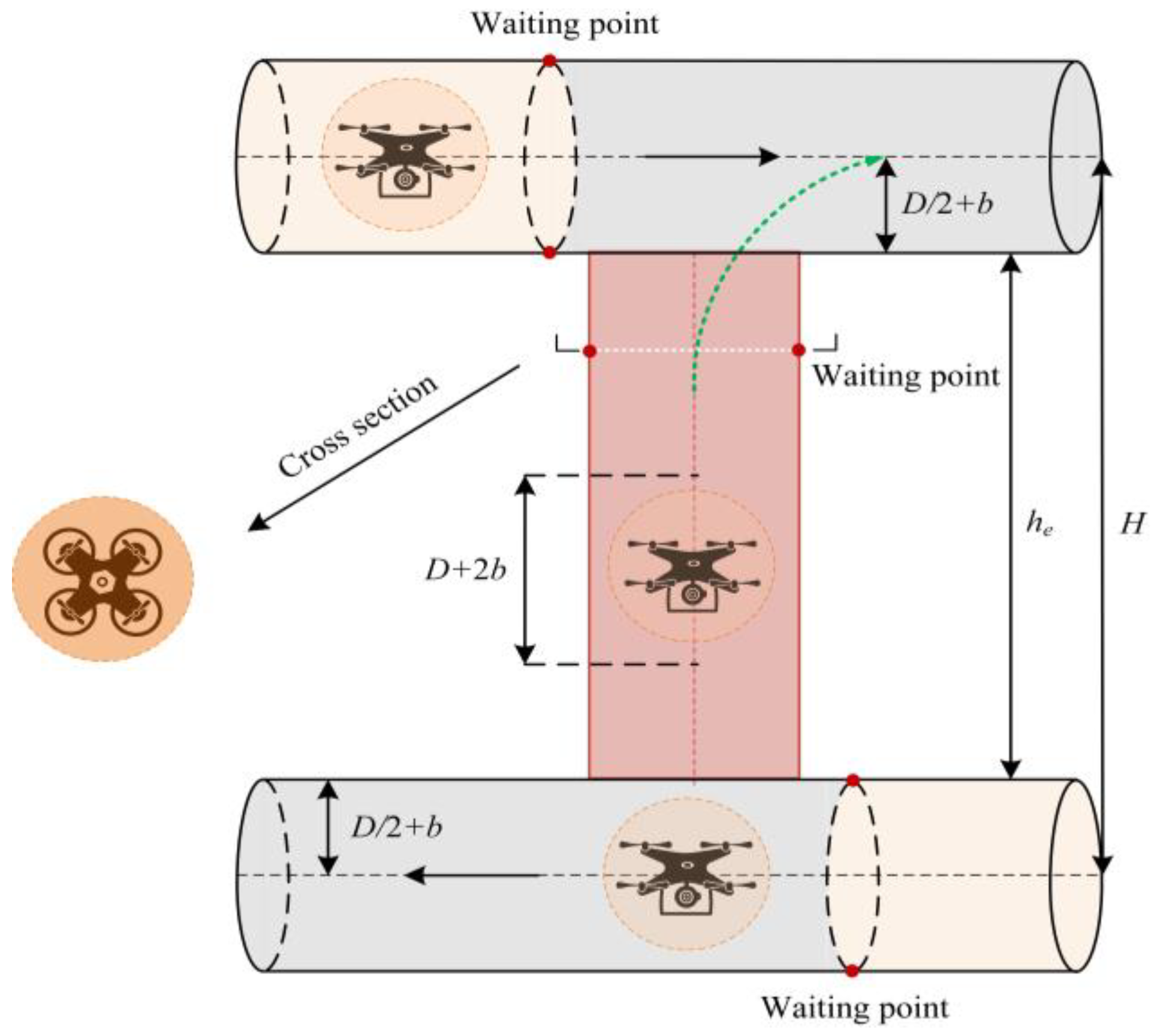
Figure 7 illustrates a cylindrical elevator connecting the upper and lower routes, whose section diameter is the same as the leg section diameter. In order to guarantee the safety of UAV operation, the distance between elevators needs to meet the horizontal safety separation of the UAV, so that its ascending and descending do not interfere with each other. When the UAV leaves the elevator, it enters the target route flight level along the green line. Considering that the along-road intersection is a single-channel operation mode, two elevators are set in the route-crossing area for the UAV to ascend and descend respectively. If the distance between adjacent flight levels is H , the elevator height h e is denoted as:
h e = H D 2 b = C 1 S v + D + 2 b
where C is the maximum capacity of the elevator. S v is the vertical separation of the UAV.
Then, the maximum capacity C of the elevator is calculated as:
C = 1 + H 2 D 4 b S v

4.1.3. Flight Procedures

(1)
Fly into
When the UAV flies from the air route to the waiting point of the intersection, if the intersection is idle, the UAV can fly directly into the intersection and then execute the turning procedure. If the intersection is occupied, the incoming UAV waits at the waiting point and flies into the intersection when the intersection is updated to the idle state. If multiple UAVs plan to fly into the intersection when the traffic flow in the route is sparse, the fly-into procedure follows the principle of first-come, first-serve; that is, the first arrived UAV has priority to enter the rotated seat. When the traffic flow is dense, the UAV needs to queue up to pass the roundabout. In order to ensure the fairness of service, the UAVs of each route enter the roundabout in turn, and the UAVs that enter the roundabout successively need to come from different routes.
(2)
Turning
If the UAV does not change the flight level, it turns along the blue line at a constant speed. When the UAV is about to fly to the exit of the target route, it executes the fly-out procedure, as shown in Figure 8a. As the number of routes connected by intersections increases, so does the number of possible turning routes for UAVs. If the UAV changes the flight level, it enters the elevator along the blue or green line and then executes the lifting procedure, as shown in Figure 8b.
(3)
Lifting
If the routes of the UAV into and out of the roundabout are not both eastward or westward routes, the UAV needs to perform a lifting procedure to change the flight course. After entering the elevator, the UAV ascends or descends at a certain speed and maintains a vertical safety separation from the preceding UAV in the elevator.
(4)
Fly out
After completing the turning procedure, if the UAV does not change flight level, it will proceed with the fly-out procedure, and the intersection status value will be updated from 1 to 0. If the UAV changes the flight level, the UAV ascends or descends in the elevator to the waiting point and judges the intersection status of the target flight level. If the target level intersection is occupied, the UAV continues to wait. If it is free, the UAV enters the target route along the blue or green line, as shown in Figure 8c. At the same time, if there are other UAVs expected to pass the intersection at the target flight level, the UAV in the elevator has the priority of passage, and then the UAVs in each direction pass alternately.

4.2. Roundabout Type

4.2.1. Operation Concept

The roundabout is a center island set at the route interchange, and the channelized traffic is organized through the circular route to form a one-way traffic flow. The control mode of the roundabout draws on the movement patterns of a carousel. A carousel is a common entertainment facility in theme parks; the area usually has a separate entrance and exit for visitors to enter and exit. Each hobbyhorse can carry one visitor, who rotates with the hobbyhorse around a central fixed axis. After the stop signal is sounded, visitors leave the carousel through the exit, and the next group of visitors can choose to take the free hobby horse.
Inspired by this, this paper proposes a carousel-like model to regulate the order of UAV traffic, as shown in Figure 9. Inside the roundabout, there are a number of hobbyhorses, called UAV rotate seats, which are evenly arranged along the circular route at equal angles and equidistant. The junction of each route and roundabout is the entrance and exit of the route and roundabout. Similar to an along-road type intersection, an elevator is provided at the junction to connect two adjacent flight levels, and the elevator follows an independent one-way driving rule. The UAV changes its flight course through the elevator, as shown in Figure 9, where the blue dotted lines and the red dotted lines represent the inbound/ascending and outbound/descending routes of the UAV, respectively.

4.2.2. Characteristic Parameters

(1)
Roundabout radius
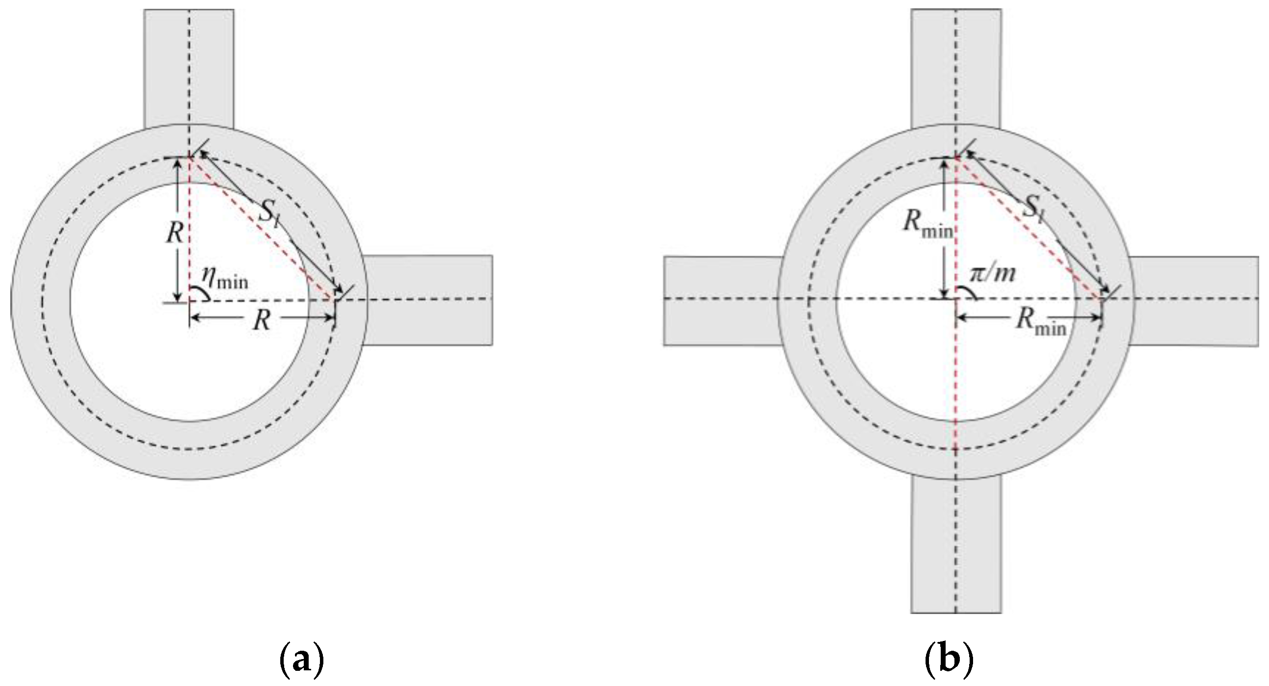
The distance between the air routes connected around the roundabout is required to meet the horizontal safety separation requirement. As shown in Figure 10a, if the UAV horizontal safety separation is S l and the roundabout radius is R , it can be obtained according to the sine theorem:
S l sin η min = R sin ( ( π η min ) / 2 )
Then, the minimum crossing angle η min corresponding to the adjacent routes can be derived as:
η min = 2 arcsin S l 2 R
There are two methods of calculating the minimum roundabout radius according to the route-crossing mode of the roundabout.
Case 1: The routes connected around the roundabout are evenly distributed along the center of the circle; that is, the angle between adjacent routes is equal. Furthermore, the distance between the centerlines of the adjacent routes is not less than the horizontal safety separation. As shown in Figure 10b, if the number of routes contained in the roundabout is m , the same as Formula (10), it can be deduced from the sine theorem that the corresponding minimum roundabout radius R min is:
R min = S l 2 s i n π 2 m
Case 2: The roundabout connects m routes, and all route extensions do not intersect at the same point. If the angles between adjacent routes are τ 1 , τ 2 , , τ m , then the minimum roundabout radius R min is denoted as:
R max r min , R min , R min
(2)
Rotate seat
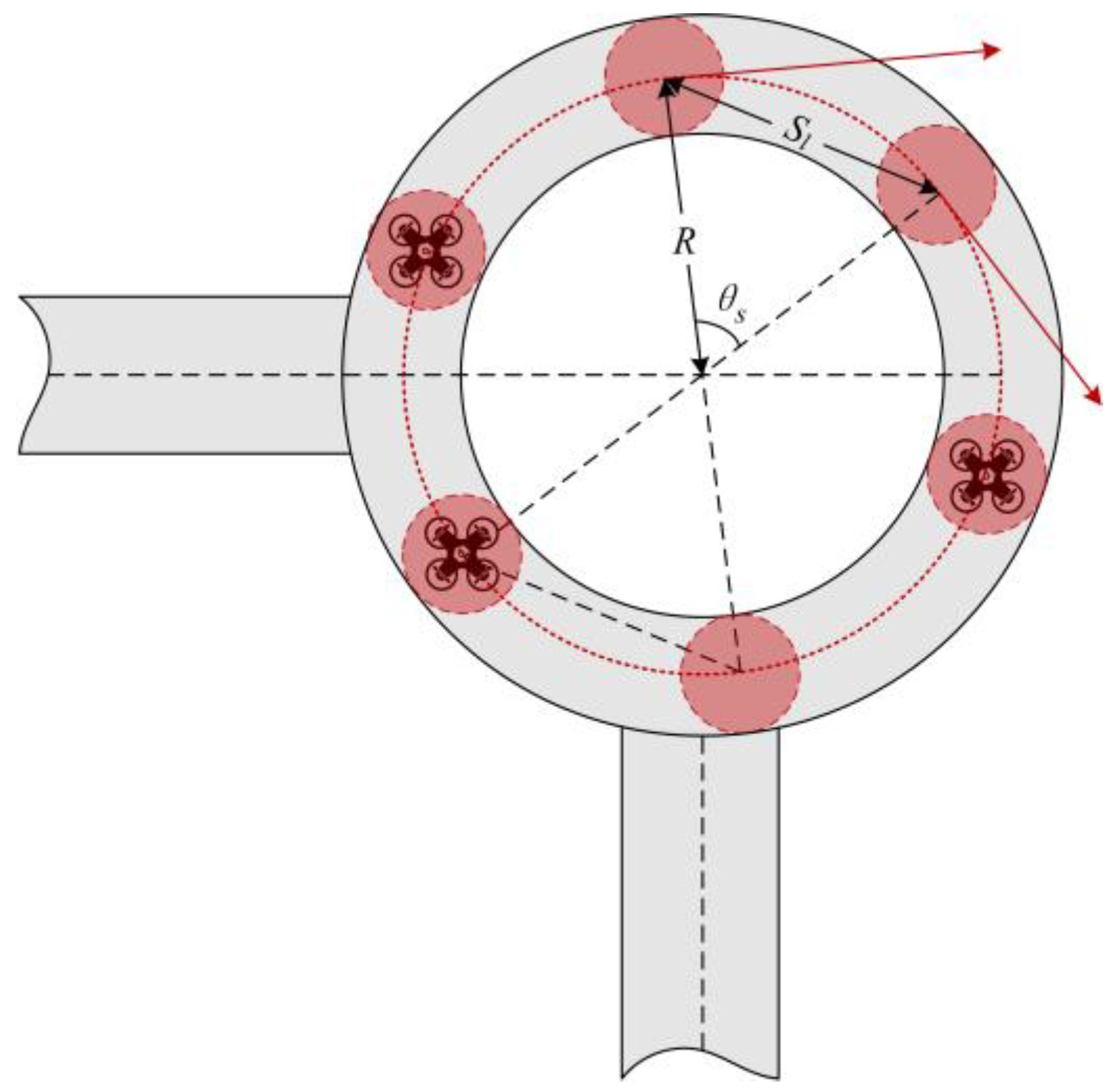
The size of the rotate seat matches the UAV-protected zone, and its diameter is consistent with the diameter of the leg cross-section. As shown in Figure 11, θ s represents the angle between the rotate seats, namely, the angle formed by the connection between two adjacent rotate seats and the roundabout center, and its size is related to the UAV safety separation and the roundabout radius. In order to ensure safe operation in the roundabout, the distance between the rotate seat needs to satisfy the safety separation between UAVs. According to the cosine theorem, θ s can be derived as:
θ s = cos 1 1 S l 2 2 R 2
Then, the maximum number of rotate seats n that can be accommodated in the roundabout is expressed as:
n = 2 π θ s = 2 π cos 1 1 S l 2 2 R 2
The rotate seat revolves around the center of the roundabout with constant angular velocity ω r . At any time t n , the position of the rotate seat center i can be calculated as:
x i t n y i t n z i t n = R · cos θ i t 0 ω r t n t 0 R · sin θ i t 0 ω r t n t 0 0 + x c y c z c
where x i t n , y i t n , z i t n respectively represent the three-dimensional coordinate values of rotate seat i in the x , y , z axes at t n ; θ i t 0 is the angle between the line connecting the roundabout center and the rotate seat i and the x axis at the initial time t 0 ; x c , y c , z c represent the coordinate values of the roundabout center in the x , y , z axes.
At t n , the state value S t a t u s i t n of rotate seat i is represented by a binary variable as:
S t a t u s i t n = 0 , Available 1 , Occupied
where S t a t u s i t n = 0 indicates that rotate seat i is not occupied by a UAV; S t a t u s i t n = 1 means that rotate seat i is occupied by a UAV. A maximum of one UAV is allowed to exist on a rotate seat at the same time. It can be seen that the rotate seats separate the UAVs in time and space, although they are not actual physical entities. The motion states of the rotate seats can be represented in a list, as shown in Table 1.
(3)
Elevator
The elevators are located in the roundabout, the number of which is equal to twice the number of routes. The number of elevators used for ascent or descent each accounts for half of the total number of elevators. The structural parameters are similar to those of the along-road type elevators.

4.2.3. Flight Procedures

(1)
Fly into
The essence of UAVs entering the roundabout is to search for vacant rotate seats. Figure 12 shows the operational status of four rotate seats with three UAVs in the roundabout. At time t 0 , two rotate seats are occupied by UAVs (red), two rotate seats are free (blue), and one UAV is waiting to enter the roundabout on the eastward route. At time t 1 , there is a rotate seat passing the waiting point of the eastward route. Since the rotate seat is occupied, the incoming UAV remains in its original state. At time t 2 , a free rotate seat passes the waiting point, and the incoming UAV enters the rotate seat along the green line, thus smoothly entering the roundabout and continuing to execute the turning procedure. When multiple UAVs are scheduled to fly into the roundabout, the order of their entry into the rotate seat is similar to that of the along-road type.
(2)
Turning
After the UAV enters the roundabout, it flies along the roundabout with the rotate seat, as shown in Figure 12. The UAV velocity is consistent with the rotate seat, and the velocity v is expressed as:
v = ω r R
If the target route of the UAV is in the same direction as the fly-into route, its flight level remains unchanged. When the UAV is about to turn to the exit of the target route, the fly-out procedure is executed. If the target route is in a different direction from the fly-into route, the lifting procedure is performed.
(3)
Lifting
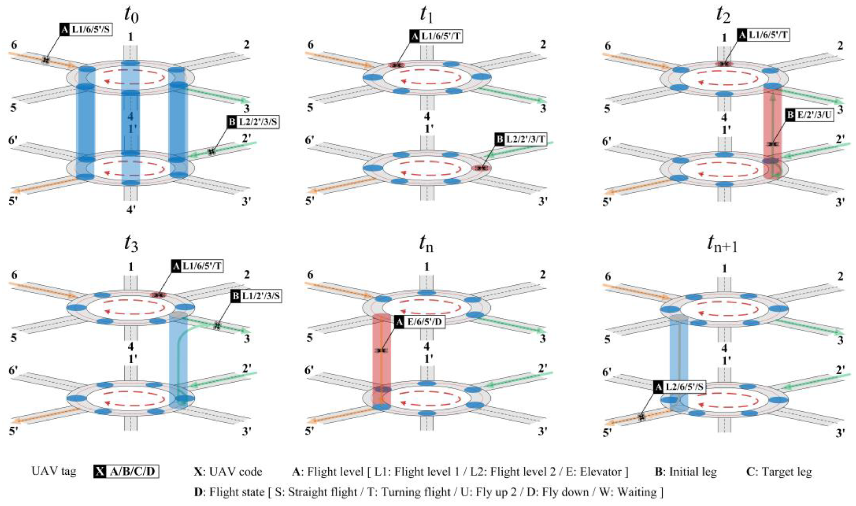
If the UAV changes flight level, it will fly to the elevator entrance corresponding to the target route at the original altitude rotate seat, change the altitude through the elevator, and then execute the fly-out procedure to turn to the opposite route. Figure 13 shows a double-layer roundabout with six legs connected to both the upper layer L1 and lower layer L2. The upper routes are all eastward, with entrances located on legs 4,5,6 and exits on legs 1,2,3. The lower routes are all westward, with entrances on legs 1 , 2 , 3 , and exits on legs 4 , 5 , 6 . At time t 0 , there are two UAVs preparing to enter the roundabout to change flight level. The target leg for UAV A entering the upper leg 6 is the lower leg 5 , as shown by the orange arrow. The target leg for UAV B entering the lower leg 2 is the upper leg 3, as indicated by the green arrow. At time t 1 , the two UAVs enter the free rotate seats respectively and execute the turning procedure. At time t 2 , UAV B enters the elevator corresponding to leg 3 to start ascending and releases the lower rotate seat. When the UAV reaches the elevator waiting point, the fly-out procedure is executed. At time t 3 , UAV B flies into the target leg along the green line. At time t n , UAV A enters the elevator corresponding to leg 5 to start descending and releases the upper rotated seat. When UAV A reaches the elevator waiting point, it executes the fly-out procedure. At time t n + 1 , UAV B flies into the target leg along the orange line.
(4)
Fly-out
If the UAV does not change the flight level when it is about to turn to the target route with the rotate seat, the fly-out procedure is performed. As shown in Figure 14, at time t 0 , there is a UAV ready to fly out of the roundabout into an eastward route. At time t 1 , it begins to adjust its heading along the green line to leave the rotate seat, and entered the target route at time t 2 . The rotate seat is shifted from the occupied state to the free state. If the UAV changes the flight level, when it reaches the waiting entry point in the elevator, after determining that there is no UAV in the rotate seat at the target flight level, it flies out of the roundabout and enters the target route.

5. Operation Evaluation

Based on the concept of the UAV route, this section defines UAV conflict risk and intersection service level metrics from two aspects of safety and efficiency, which lays a foundation for subsequent simulation experiments in order to quantitatively assess the operational posture of intersections.
(1)
Conflict risk
If two UAVs k f and k b are flying in the air route and pass the same intersection successively. A flight conflict occurs when one UAV intrudes into the protected zone of the other UAV. The conflict condition when the UAV passes the intersection is defined as follows:
d k f k b D
where d k f k b is the distance between the spherical centers of the two UAV-protected zones.
UAVs have mutually independent track errors in the longitudinal, lateral and vertical directions, consistent with a three-dimensional Gaussian distribution [29,31]. UAV conflict risk can be quantified by conflict probability. At time t , the flight conflict probability between two UAVs can be considered as the product of the conflict probabilities in the three directions, then:
P ( t d k f k b D ) = P ( t Δ d x D ) × P ( t Δ d y D ) × P ( t Δ d z D )
where Δ d x , Δ d y , Δ d z are the relative distances of the two UAVs along the x , y , z axes, respectively.
For the axis x , the probability that there is a conflict between the two UAVs can be calculated as:
P ( t Δ d x D ) = 1 2 π ( σ 1 x 2 + σ 2 x 2 ) D D exp ( x Δ d x ) 2 2 ( σ 1 x 2 + σ 2 x 2 ) d x
where σ 1 x , σ 2 x are the standard deviations of the track errors of the two UAVs. The conflict probabilities along the y and z axes are calculated in the same way.
(2)
Service level
The intersection level of service is measured using the intersection passing rate and average passing time. The intersection passing rate is the ratio of intersection throughput to total departing UAV sorties, where the throughput is the number of UAV sorties passing the intersection range per unit time.
If there are u UAVs scheduled to cross the intersection within a unit of time, the intersection passing rate C u a v can be expressed as:
C u a v = i = 1 m j = 1 m k = 1 u f i j k u
where f i j k is a 0–1 discrete variable. f i j k = 1 indicates that the k th UAV flies into route j from route i through the intersection range, and f i j k = 0 means that the UAV does not fly into or out of the intersection range.
The intersection passing time Δ t i j k of the k th UAV flying from route i to route j can be denoted as:
Δ t i j k = t i j k d e p t i j k e n t
where t i j k d e p is the moment when the UAV leaves the intersection range, and t i j k e n t is the moment when the UAV enters the intersection range.
Then, the average passing time W u a v of the UAV through the intersection is represented as:
W u a v = i = 1 m j = 1 m k = 1 u f i j k Δ t i j k i = 1 m j = 1 m k = 1 u f i j k

6. Simulation Experiments

6.1. Scenario Setting

Since standardized urban low-altitude air routes have not yet been formed, it is difficult to use real UAVs for verification. Therefore, the UAV traffic flow is imitated through simulation experiments to analyze the performance of each route type. In this section, urban UAV transportation is taken as an example. In the height range of 60 to 90 m in the urban area, a double-layer standard intersection formed by 2, 3, and 4 air routes intersecting at equal angles, namely, the angle of adjacent air routes is 90°, 60°, and 45° respectively. The average arrival rate of UAVs flying to the intersection of each route is 1–6 veh/min. Three types of UAVs, the Mavic Air 2, Inspire 2, and M300 RTK, are selected for simulation, with a ratio of 3:5:2 among them, and the UAV maximum rolling angle is 45°. According to the UAV structural parameters, the air route width is set to 4 m based on the UAV with the largest wheelbase. Each UAV is randomly assigned the target route, with 20% of the UAVs changing flight level at intersections. According to UAV performance parameters [32,33,34] and reference [35], the safety separations between UAVs are described in Table 2. The radius r a r e a of the intersection is 50 m. Since the UAV has to control its flight speed before entering the intersection, its speed through the along-road intersection is set to 6 m/s, and the angular speed through the roundabout is set to 15°/s. The elevator height is 30 m, the ascending speed in the elevator is 4 m/s, the descending speed is 3 m/s, and the radius of the roundabout is set to 25 m.

6.2. Experimental Design

Based on the above information, the following experiments are designed to simulate the UAV traffic flow, analyze the performance characteristics of the along-road and roundabout intersections in terms of safety and efficiency, and explore the change rule of the air route operation posture by adjusting the UAV arrival rate.
Experiment 1: Security analysis. For along-road and roundabout intersections, calculate the conflict probabilities of two-road, three-road, and four-road intersections and analyze the impact of the number of UAVs on the intersection operation safety.
Experiment 2: Efficiency analysis. Under the same UAV arrival rate, calculate the UAV passing time of two-road, three-road, and four-road intersections to compare and analyze the passing efficiency of the along-road and roundabout intersections.
Experiment 3: Randomness analysis. Randomly adjust the number of UAVs arriving at the intersection, namely, the arrival rate fluctuates between 1 veh/min and 6 veh/min, to analyze the service level at intersections within a certain time window.

6.3. Result Analysis

6.3.1. Security Analysis

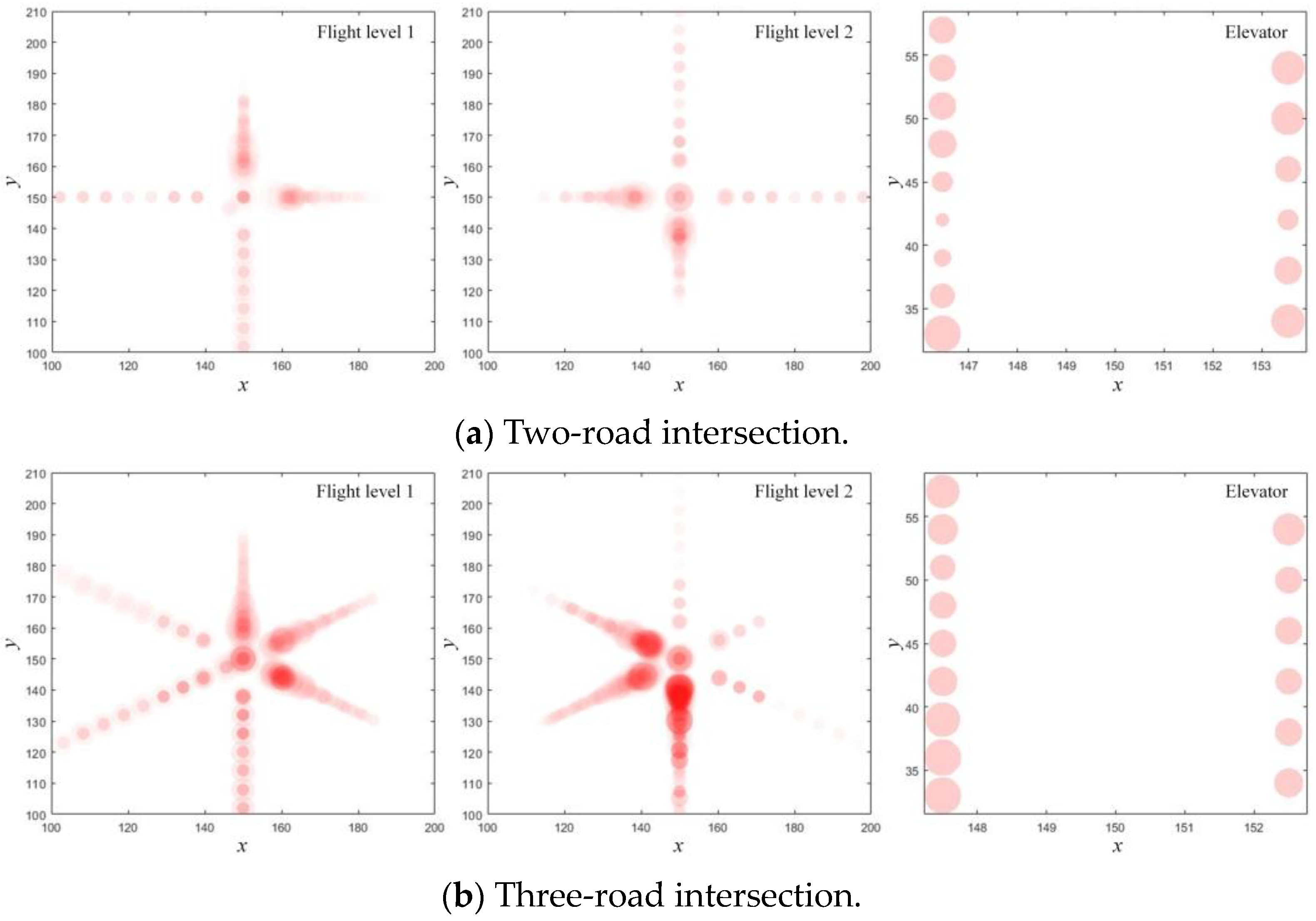
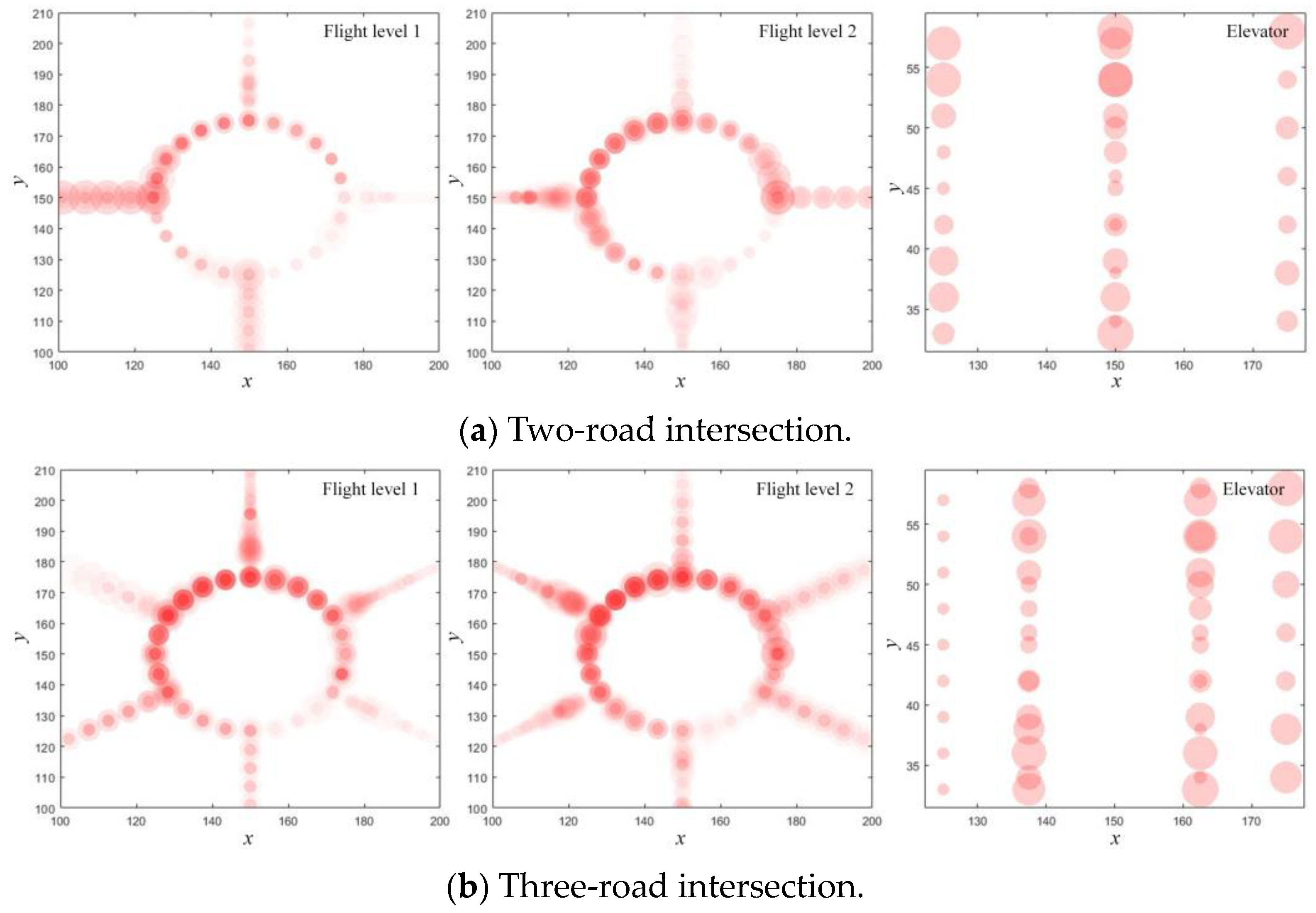
In the 450 s time window, the conflict risk simulation results of Experiment 1 are shown in Figure 15 and Figure 16. The darker the color and the larger the bubbles, the higher the probability of UAV conflict. The lighter the color and the smaller the bubbles, the lower the conflict probability. For along-road intersections, the risk-intensive areas are mainly located in the route-crossing area and show a tendency to extend outward along the route, with less conflict risk within the elevator and general route, as shown in Figure 15. During peak hours, when a UAV enters the crossing area, other pending UAVs need to hover at the route waiting point. At this time, there are two mixed operating states of UAVs, which are prone to cause intersection congestion and promote risk propagation. Meanwhile, the close proximity between the moving UAV and the hovering UAV will further increase the probability of conflict.
For roundabout intersections, the risk-intensive areas are mainly distributed in the circular route, the junction of the roundabout and the route, and the junction of the elevator and the roundabout, with less conflict risk within the elevator and general route, as shown in Figure 16. During peak hours, there may be three kinds of UAVs operating in the roundabout at the same time: (1) hovering and waiting. The UAV primarily hovers outside the roundabout at the waiting point or inside the elevator, waiting to enter the roundabout through the available rotate seat; (2) flying around the roundabout. The UAV is circling the loop or just entering the elevator through the roundabout; (3) flying out of the roundabout. One type of UAV has just flown out of the roundabout at the same flight level, and the other type of UAV has just passed through the elevator into the target route. Therefore, the intersection risk is higher and concentrated at points where the operational state of the UAV changes, which is an inherent property of route intersections. Since the elevator and route are unidirectional, the risk mainly comes from the vertical and horizontal conflict risk between UAVs, respectively. Compared with the along-road intersection, the roundabout has relatively large separations between the routes, which can effectively reduce the conflict probability between UAVs.
The scale of UAVs operating at intersections is also a key factor affecting conflict risk. The correlation between the number of UAVs and conflict risk is explored through regression analysis, and the results are shown in Table 3. The number of UAVs is positively correlated with conflict risk, and the greater the number of routes, the stronger the correlation and the greater the conflict risk. For two-road or three-road intersections, the mean risk of the roundabout is higher than that of the along-road type, while for four-road intersections, the mean risk of the along-road type is significantly higher than that of the roundabout. This paper suggests that the main reason for this phenomenon is the complex structure of the roundabout. When the number of routes is small, the number of crosspoints is much higher than that of the along-road type, which increases the conflict risk. As the number of routes increases, the single-channel pattern of the along-road type greatly constrains traffic capacity, resulting in route congestion and risk propagation, leading to a higher mean risk level than that of the roundabout.

6.3.2. Efficiency Analysis

The average time of UAV passing through the intersection range in Experiment 2 is presented in Table 4. When the number of crossing routes is small, or the UAV arrival rate is low, the passing time of the along-road intersection is obviously less than that of the roundabout intersection. For example, when the UAV arrival rate at the two-road intersection is 1 veh/min, the average passing time of all UAVs at the along-road intersection is about 2 s faster than that of the roundabout. When the UAV arrival rate at the three-road and four-road intersections is 1–3 veh/min, the average passing time of the along-road intersections is shorter, and the UAV passing efficiency is higher. At this time, for roundabout intersections, the flight efficiency is lower because the UAV needs to fly along the circular route, which leads to an increase in flight distance.
With the increase in the number of crossing routes and the UAV arrival rate, the passing times of the along-road intersections begin to be smaller than that of the roundabout intersections. For example, when the UAV arrival rate at the four-road intersection is 6 veh/min, the average passing time of all UAVs at the along-road intersection is about 17 s slower than that of the roundabout. Compared to the four-road intersection with the UAV arrival rate of 1 veh/min, the average passing time increase is as high as 87% for the along-road intersection and only 18% for the roundabout intersection. This is due to the along-road intersection belonging to the single-channel mode. As the UAV arrival rate increases, the intersection may be congested. The UAVs gathered here from various routes may need to hover and wait to pass through the route-crossing area in turn, and then the congestion shows a tendency to spread from the route-crossing area to the routes. For roundabout intersections, the route-crossing area is separated by rotate seats, and the interaction of UAVs between routes is small. UAVs on different routes are able to enter the roundabout at the same time to form channelized traffic. Since the main factors that affect the operation efficiency of the roundabout are the time window allocation of the rotate seat and the UAV detour speed, the efficiency advantage of the roundabout intersection becomes apparent when the number of crossing routes increases and the air traffic volume increases.

6.3.3. Randomness Analysis

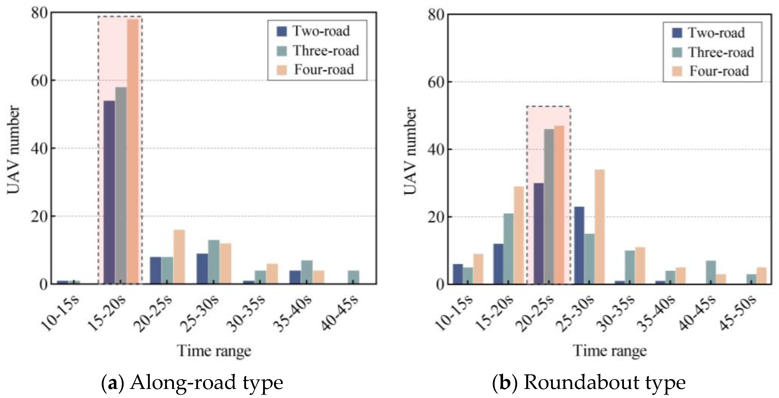
The operational characteristics of the two intersections are further analyzed through randomized tests in Experiment 3. Figure 17 demonstrates the distribution diagram of intersection passing time, where the red boxes indicate the passing time range of most UAVs. It can be seen that the passing time of the along-road intersections is mainly concentrated in the range of 15–20 s, and the passing time of the roundabout intersections is mainly concentrated in the interval of 20–25 s. Table 5 shows the simulation results of the intersection service level. The number of crossing routes is positively correlated with the passing time and negatively correlated with the passing rate. When the number of crossing routes is small, the passing rate of the along-road intersection is higher. As the number of crossing routes increases, the efficiency of the roundabout intersection is better, which is consistent with the conclusion of Experiment 2.
In order to analyze the traffic capacity of different types of intersections, 30 UAVs are sent to each route to enter the intersection on the premise of maintaining a safe separation between UAVs, and the intersection access conditions within the 450 s time window are analyzed. The simulation results are shown in Figure 18. In the initial phase, a period of about 0 to 50 s, UAVs enter the intersection in a continuous and steady rhythm, making the number of UAVs show a significant growth trend. Then, the number of UAVs within the intersection fluctuates up and down within a certain number range, and a dynamic balance is formed between the flow of UAVs flying in and out. Since the total number of UAVs remains constant, the number of UAVs at the intersection gradually decreases as UAVs continue to fly out of the intersection. In addition, the red circles in Figure 18 indicate the maximum number of UAVs that can be carried by the intersections. It can be seen that the maximum number of UAVs that can be carried by along-road intersections is close to that of the roundabout intersections, and the value is positively correlated with the number of crossing routes. Within the specified time window, the along-road intersections, with the exception of the two-road intersection, the three-road and four-road intersections, are not able to fulfill all the UAV traffic requirements. However, the roundabout intersections can basically meet all the traffic needs of UAVs.

7. Conclusions

Considering the complexity and management difficulty of large-scale UAV mixed flight, this paper designs an urban low-altitude multi-rotor UAV route configuration by combining the structural airspace characteristics and UAV flight performance. Meanwhile, mainly focusing on the along-road type and roundabout type intersections, the evaluation metrics are established from the aspects of UAV operation safety and efficiency to realize the quantitative analysis of the operation posture of the two intersections. The main contributions of this work are as follows:
(1)
The traffic management strategies for intersections are proposed, including operation concepts, characteristic parameters, and flight procedures, and traffic flow characteristics in urban UAV transportation scenarios are simulated through experiments. The results show that there is a positive correlation between the number of UAVs at intersections and the conflict risk, and the more crossing routes, the stronger the correlation. The number of crossing routes is negatively correlated with the intersection passing rate, and the intersection average passing time shows a growing trend with the growth of the UAV arrival rate.
(2)
The influence of the number of routes on the operation situation of intersections is analyzed from two aspects: safety and efficiency. When the number of routes connected by the intersection is small, the overall conflict risk of the roundabout type is higher than that of the along-road type, and with the increase in the crossing routes, the overall conflict risk of the along-road type is higher than that of the roundabout type. However, the operational efficiency of the along-road type is higher than that of the roundabout type when the number of crossing routes or UAV arrival rate is low, and the operational efficiency of the traffic circle type is gradually better than that of the along-road type as the number of cross routes or arrival rate grows. The along-road type is suitable for scenarios with fewer crossing routes and relatively sparse UAV traffic, while the roundabout type is more suitable for environments with more crossing routes and dense UAV traffic.
In summary, this study provides an air route design method that is helpful to realize the standardized management of UAVs. The existing research tends to design the macro-structure of the route in free airspace, and the turning and obstacle avoidance of UAVs depends on autonomous control ability, lacking normative and interactive guidance. This method pays more attention to route configuration and flight procedure design and finely standardizes the whole operation process of UAV flying into, turning, lifting and flying out at multi-route intersections to ensure flight safety and efficiency. This study is mainly aimed at multi-rotor UAV and standardized parameter configuration, and further research is needed on the adaptability and coordination between route structure and UAV in the future. On the one hand, the UAV speed affects its flight performance and has a non-negligible impact on the intersection operation situation. It can distinguish the design of high-speed routes from ordinary routes and guide UAVs with different performances in order to improve traffic fluency. On the other hand, in order to achieve a more detailed route design, it is necessary to further explore the impact of UAV types on the route configuration, expand the route design to fixed-wing UAVs, and continuously improve the intersection operation procedures to ensure that the route can better adapt to the evolving traffic environment and needs.

Author Contributions

S.L.: conceptualization, methodology, validation, visualization, and writing—original draft. H.Z.: funding acquisition, resources, and supervision. Z.L.: software, data curation, formal analysis, visualization, and writing—original draft. H.L.: investigation, project administration, and writing—review and editing. All authors have read and agreed to the published version of the manuscript.

Funding

This work was funded by the National Social Science Fund of China [Grant number: 22&ZD169]; Postgraduate Research & Practice Innovation Program of Jiangsu Province [Grant number: KYCX23_0392]; and the China Scholarship Council [Grant number: 202406830094].

Data Availability Statement

Data will be made available on request.

Conflicts of Interest

The authors declare that there are no known competing financial interests or personal relationships that could have appeared to influence the work reported in this paper.

References

  1. Zhang, H.; Zou, Y.; Zhang, Q.; Liu, H. Future urban air mobility management: Review. Acta Aeronaut. Astronaut. Sin. 2021, 42, 82–106. [Google Scholar]
  2. Aslan, S.; Erkin, T. A multi-population immune plasma algorithm for path planning of unmanned combat aerial vehicle. Adv. Eng. Inform. 2023, 55, 101829. [Google Scholar] [CrossRef]
  3. Li, S.; Zhang, H.; Yi, J.; Liu, H. A bi-level planning approach of logistics unmanned aerial vehicle route network. Aerosp. Sci. Technol. 2023, 141, 108572. [Google Scholar] [CrossRef]
  4. Li, S.; Zhang, H.; Li, Z.; Liu, H. An air route network planning model of logistics UAV terminal distribution in urban low altitude airspace. Sustainability 2021, 13, 13079. [Google Scholar] [CrossRef]
  5. Liao, X.; Qu, W.; Xu, C.; He, H.; Wang, J.; Shi, W. A review of urban air mobility and its new infrastructure low-altitude public routes. Aeronaut. Astronaut. Sin. 2023, 44, 6–34. [Google Scholar]
  6. Zhou, Y.; Su, Y.; Xie, A.; Kong, L. A newly bio-inspired path planning algorithm for autonomous obstacle avoidance of UAV. Chin. J. Aeronaut. 2021, 34, 199–209. [Google Scholar] [CrossRef]
  7. Wang, S.; Cao, X.; Li, H.; Li, Q.; Hang, X.; Wang, Y. Air route network optimization in fragmented airspace based on cellular automata. Chin. J. Aeronaut. 2017, 30, 1184–1195. [Google Scholar] [CrossRef]
  8. Niu, Y.; Yan, X.; Wang, Y.; Niu, Y. 3D real-time dynamic path planning for UAV based on improved interfered fluid dynamical system and artificial neural network. Adv. Eng. Inform. 2024, 59, 102306. [Google Scholar] [CrossRef]
  9. Hu, G.; Du, B.; Chen, K.; Wei, G. Super eagle optimization algorithm based three-dimensional ball security corridor planning method for fixed-wing UAVs. Adv. Eng. Inform. 2024, 59, 102354. [Google Scholar] [CrossRef]
  10. Gugan, G.; Haque, A. Path planning for autonomous drones: Challenges and future directions. Drones 2023, 7, 169. [Google Scholar] [CrossRef]
  11. Soltani, A.R.; Tawfik, H.; Goulermas, J.Y.; Fernando, T. Path planning in construction sites: Performance evaluation of the Dijkstra, A*, and GA search algorithms. Adv. Eng. Inform. 2022, 16, 291–303. [Google Scholar] [CrossRef]
  12. Zhang, H.; Li, H.; Liu, H.; Xu, W.; Zou, Y. Path planning for logistics unmanned aerial vehicle in urban area. J. Transp. Syst. Eng. Inf. Technol. 2020, 20, 22–29. [Google Scholar]
  13. Shao, Q.; Li, J.; Li, R.; Zhang, J.; Gao, X. Study of urban logistics drone path planning model incorporating service benefit and risk cost. Drones 2022, 6, 418. [Google Scholar] [CrossRef]
  14. Phung, M.D.; Ha, Q.P. Safety-enhanced UAV path planning with spherical vector-based particle swarm optimization. Appl. Soft Comput. 2021, 107, 107376. [Google Scholar] [CrossRef]
  15. Jiang, W.; Lyu, Y.; Li, Y.; Guo, Y.; Zhang, W. UAV path planning and collision avoidance in 3D environments based on POMPD and improved grey wolf optimizer. Aerosp. Sci. Technol. 2022, 121, 107314. [Google Scholar] [CrossRef]
  16. Aslan, S. An immune plasma algorithm with a modified treatment schema for UCAV path planning. Eng. Appl. Artif. Intel. 2022, 112, 104789. [Google Scholar] [CrossRef]
  17. Dai, R.; Fotedar, S.; Radmanesh, M.M. Kumar, Quality-aware UAV coverage and path planning in geometrically complex environments. Ad Hoc Netw. 2018, 73, 95–105. [Google Scholar] [CrossRef]
  18. Patley, A.; Bhatt, A.; Maity, A.; Kumar, S.R.; Das, K. Modified particle swarm optimization based path planning for multi-UAV formation. In Proceedings of the AIAA SciTech Forum, San Diego, CA, USA, 7–11 January 2019. [Google Scholar]
  19. Gharibi, M.; Boutaba, R.; Waslander, S.L. Internet of drones. IEEE Access 2016, 4, 1148–1162. [Google Scholar] [CrossRef]
  20. Xu, C. Planning and Construction of the Low-Altitude Public Air Route Network of UAVs by Remote Sensing Data and Geographical Information Technology. Ph.D. Thesis, University of Chinese Academy of Sciences, Beijing, China, 2020. [Google Scholar]
  21. Quan, Q.; Li, M.; Fu, R. Sky highway design for dense traffic. IFAC-PapersOnLine 2021, 54, 140–145. [Google Scholar] [CrossRef]
  22. Jang, D.S.; Ippolito, C.; Sankararaman, S.; Stepanyan, V. Concepts of airspace structures and system analysis for UAS traffic flows for urban areas. In Proceedings of the AIAA Information Systems-AIAA Infotech@Aerospace, Grapevine, TX, USA, 9–13 January 2017. [Google Scholar]
  23. Lowry, M.R. Towards high density urban air mobility. In Proceedings of the Aviation Technology, Integration, and Operations Conference, Atlanta, GA, USA, 25–29 June 2018. [Google Scholar]
  24. Sunil, E.; Ellerbroek, J.; Hoekstra, J.M.; Maas, J. Three-dimensional conflict count models for unstructured and layered airspace designs. Transp. Res. Part C Emerg. Technol. 2018, 95, 295–319. [Google Scholar] [CrossRef]
  25. Sunil, E.; Ellerbroek, J.; Hoekstra, J.; Vidosavljevic, A.; Arntzen, M.; Bussink, F.; Nieuwenhuisen, D. Analysis of airspace structure and capacity for decentralized separation using fast-time simulations. J. Guid. Control Dyn. 2017, 40, 38–51. [Google Scholar] [CrossRef]
  26. Arntzen, M.; Aalmoes, R.; Bussink, F.J.L.; Sunil, E.; Hoekstra, J. Noise Computation for Future Urban Air Traffic Systems; Report No.: NLR-TP-2015-289; National Aerospace Laboratory: Amsterdam, The Netherlands, 2015. [Google Scholar]
  27. Reich, P.G. Analysis of long-range air traffic systems: Separation standards—I. J. Nav. 1966, 19, 88–98. [Google Scholar] [CrossRef]
  28. Brooker, P. Lateral collision risk in air traffic track systems: A ‘Post-Reich’ event model. J. Nav. 2003, 56, 399–409. [Google Scholar] [CrossRef]
  29. Zou, Y.; Zhang, H.; Zhong, G.; Liu, H.; Feng, D. Collision probability estimation for small unmanned aircraft systems. Reliab. Eng. Syst. Saf. 2021, 213, 107619. [Google Scholar] [CrossRef]
  30. Nguyen, D.D.; Rohacs, J.; Rohacs, D. Autonomous flight trajectory control system for drones in smart city traffic management. ISPRS Int. J. Geo-Inf. 2021, 10, 338. [Google Scholar] [CrossRef]
  31. Zou, Y.; Zhang, H.; Feng, D.; Liu, H.; Zhong, G. Fast collision detection for small unmanned aircraft systems in urban airspace. IEEE Access 2021, 9, 16630–16641. [Google Scholar] [CrossRef]
  32. DJI-Innovations. Support for Mavic 2. 2024. Available online: https://www.dji.com/hk-en/support/product/mavic-2 (accessed on 12 June 2024).
  33. DJI-Innovations, Inspire 2 Specs. 2024. Available online: https://www.dji.com/hk-en/inspire-2/specs (accessed on 12 June 2024).
  34. DJI-Innovations, Matrice 300 RTK Specs. 2024. Available online: https://enterprise.dji.com//hk-en/matrice-300/specs (accessed on 12 June 2024).
  35. Zou, Y. Research on the Demarcation Method of Safe Separation for Unmanned Aerial Vehicle in Future Smart Cities. Master’s Thesis, University of Aeronautics and Astronautics, Nanjing, China, 2021. [Google Scholar]
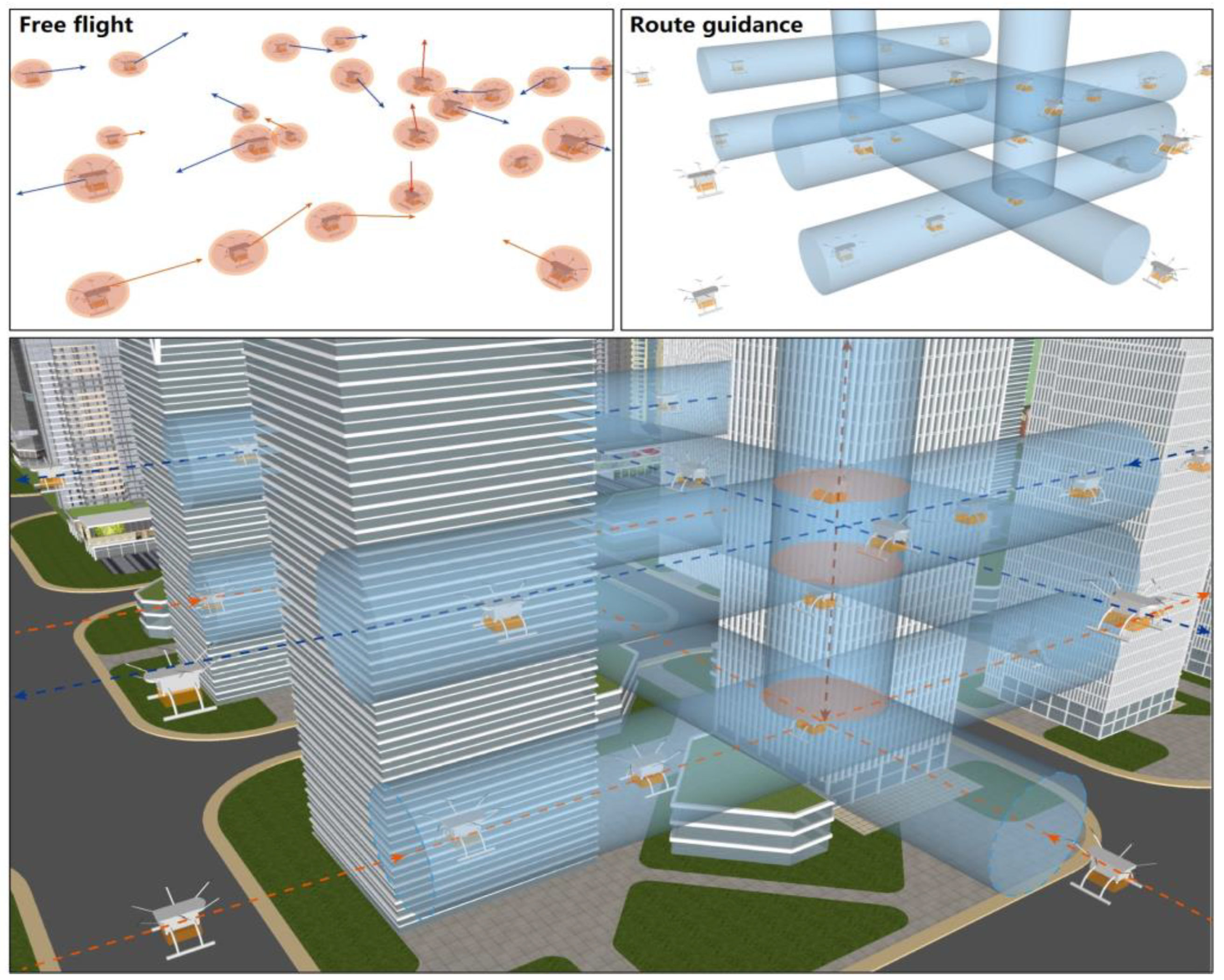
Figure 1. Schematic diagram of UAV operation in low altitude airspace.
Drones 08 00601 g001
Figure 2. UAV spherical protected zone. (a) Sphere-protected zone. (b) Top view. (c) Front view.
Drones 08 00601 g002
Figure 3. Leg micro-configuration. (a) Top view. (b) Cross-section view.
Drones 08 00601 g003
Figure 4. UAV track crossing type. (a) Free type. (b) Along-road type. (c) Roundabout type.
Drones 08 00601 g004
Figure 5. Along-road type intersection operation mode.
Drones 08 00601 g005
Figure 6. Overhead view of crossing air routes.
Drones 08 00601 g006
Figure 7. Schematic diagram of the elevator.
Drones 08 00601 g007
Figure 8. Schematic of the UAV flight route at along-road intersections. (a) Turn at the same level. (b) Turn at different levels. (c) Fly-out of intersection.
Drones 08 00601 g008
Figure 9. Roundabout operation mode.
Drones 08 00601 g009
Figure 10. Schematic diagram of characteristic parameters of the roundabout. (a) Route-crossing angle. (b) Roundabout radius.
Drones 08 00601 g010
Figure 11. Schematic diagram of the roundabout rotate seat.
Drones 08 00601 g011
Figure 12. Process of the UAV flying into the roundabout.
Drones 08 00601 g012
Figure 13. Process of the UAV changing flight level.
Drones 08 00601 g013
Figure 14. Process of the UAV flying out of the roundabout.
Drones 08 00601 g014
Figure 15. Conflict risk of along-road intersections.
Drones 08 00601 g015aDrones 08 00601 g015b
Figure 16. Conflict risk of roundabout intersections.
Drones 08 00601 g016aDrones 08 00601 g016b
Figure 17. Intersection passing time distribution diagram.
Drones 08 00601 g017
Figure 18. Traffic capacity of different types of intersections.
Drones 08 00601 g018
Table 1. Rotate seat timing states.
Rotate Seat Codet0t1⋯⋯tn
PositionStatusPositionStatusPositionStatusPositionStatus
1x1(t0),y1(t0),z1(t0)0x1(t1),y1(t1),z1(t1)1⋯⋯⋯⋯x1(tn),y1(tn),z1(tn)1
2x2(t0),y2(t0),z2(t0)1x2(t1),y2(t1),z2(t1)0⋯⋯⋯⋯x2(tn),y2(tn),z2(tn)0
3x3(t0),y3(t0),z3(t0)1x3(t1),y3(t1),z3(t1)1⋯⋯⋯⋯x3(tn),y3(tn),z3(tn)0
⋯⋯⋯⋯⋯⋯⋯⋯⋯⋯⋯⋯⋯⋯⋯⋯⋯⋯
nxn(t0),yn(t0),zn(t0)1xn(t1),yn(t1),zn(t1)1⋯⋯⋯⋯xn(tn),yn(tn),zn(tn)0
Table 2. UAV safety separations.
TypeMavic Air 2Inspire 2M300 RTK
Mavic Air 2Vertical: 2 m
Horizontal: 10 m
Vertical: 2 m
Horizontal: 15 m
Vertical: 3 m
Horizontal: 20 m
Inspire 2Vertical: 2 m
Horizontal: 15 m
Vertical: 1 m
Horizontal: 15 m
Vertical: 2 m
Horizontal: 20 m
M300 RTKVertical: 3 m
Horizontal: 15 m
Vertical: 2 m
Horizontal: 10 m
Vertical: 2 m
Horizontal: 25 m
Table 3. Relationship between the UAV scale and intersection conflict risk.
TypeAlong-RoadRoundabout
Mean RiskMean UAV NumberRelative CoefficientMean RiskMean UAV NumberRelative Coefficient
Two-road0.02%3.40.310.05%60.38
Three-road0.06%6.20.530.07%8.50.56
Four-road0.36%15.60.730.11%11.50.67
Table 4. The average time of passing through the intersection ranges under different arrival rates.
Arrival Rate (veh/min)Along-Road Type
Average Passing Time (s)
Roundabout Type
Average Passing Time (s)
Two-RoadThree-RoadFour-RoadTwo-RoadThree-RoadFour-Road
117.3918.6323.6519.4822.522.66
1.518.6418.9823.8720.2223.6323
219.3721.2824.2520.5423.9123.07
2.519.7321.5424.3420.6324.123.36
320.5522.7124.7220.8824.2723.72
3.521.2223.0326.7221.0424.5524.08
421.2423.2727.6121.2525.0324.73
4.521.623.4731.1522.1425.0625.04
521.7723.4931.2522.3925.1325.91
5.521.9623.6338.123.0925.526.04
622.8526.0544.1323.2425.6726.79
Table 5. Service levels at different types of intersections.
TypeAverage Passing Time (s)Average Passing Rate
Along-roadTwo-road20.5867.98%
Three-road23.2544.52%
Four-road23.8130.19%
RoundaboutTwo-road23.359.55%
Three-road2440.38%
Four-road23.9237.21%
Disclaimer/Publisher’s Note: The statements, opinions and data contained in all publications are solely those of the individual author(s) and contributor(s) and not of MDPI and/or the editor(s). MDPI and/or the editor(s) disclaim responsibility for any injury to people or property resulting from any ideas, methods, instructions or products referred to in the content.