Article

A Nonlinear Adaptive Control and Robustness Analysis for Autonomous Landing of UAVs

by
Yue Feng
1,
Quanwen Hu
2,
Weihan Wu
1,
Liaoni Wu
2,
Qiuquan Guo
1 and
Haitao Zhang
1,*
1
Shenzhen Institute for Advanced Study, University of Electronic Science and Technology of China, Shenzhen 518110, China
2
School of Aerospace Engineering, Xiamen University, Xiamen 361102, China
*
Author to whom correspondence should be addressed.
Drones 2024, 8(10), 587; https://doi.org/10.3390/drones8100587
Submission received: 19 September 2024 / Revised: 11 October 2024 / Accepted: 13 October 2024 / Published: 17 October 2024

Abstract

:
The UAV landing process has higher requirements for automatic flight control systems due to factors such as wind disturbances and strong constraints. Considering the proven effective adaptation of the out-of-loop L1 adaptive control (OLAC) system proposed in previous studies, this paper applies it to landing control to enhance robustness and control accuracy in the presence of complex uncertainties. Based on modern control theory, an LQR-based OLAC algorithm for multi-input–multi-output (MIMO) systems is proposed, which is conducive to the coupling control of the flight attitude mode. To evaluate the robustness of the designed system, an equivalence stability margin analysis method for nonlinear systems is proposed based on parameter linearization. Along with a detailed autonomous landing strategy, including trajectory planning, control, and guidance, the effectiveness of the proposed methods is verified on a high-fidelity simulation platform. The Monte–Carlo simulation is implemented in the time domain, and the results demonstrate that OLAC exhibits strong robustness and ensures the state variables strictly meet the flight safety constraints.

1. Introduction

With the rapid development of technology, UAVs have been widely used in both civilian and military fields, particularly in three-dimensional transportation and the low-altitude economy. These complex systems exhibit nonlinearity, time-varying parameters, and modal coupling, often encountering external environment disturbances such as wind, turbulence, and sensor drift [1,2,3]. Amongst various flight phases, autonomous landing stands out as one of the most intricate processes. Wheeled landing serves as a common approach, offering benefits such as minimal airframe damage and cost efficiency while accompanied by high risks. Notably, runway overruns, control failures, and excessively high sink rates at the landing point constituted the top three causes of international civil aviation accidents between 1959 and 2019 [4]. The control and guidance of the gliding phases pose a significant challenge within the autonomous landing process [5]. To address the issue of excessive sink rates at the landing point, various descent trajectories utilizing different slope lines and exponential forms have been successively proposed [6,7,8]. Accurate trajectory tracking is a prerequisite for these trajectory planning methods to be effective. The landing process is susceptible to wind interference. Thus, a control system with high robustness is necessary to ensure the landing performance amidst complex uncertainties.
Due to the unique ability to adapt, adaptive control [9] has achieved extensive theoretical research and engineering application in the fields of aviation and aerospace, which has greatly enhanced the reliability of flight control systems [10,11]. Due to the constraints of strict theoretical assumptions, the realization of adaptive control has been quite a challenging problem. NASA has conducted a series of research studies on the robust modification of adaptive control systems, which has contributed to the improvement in system stability, robustness, and adaptivity [12,13,14]. The proposed algorithm has been effectively implemented on typical aircraft models, including the F/A-18A and F-15 [15,16,17]. Based on the model reference adaptive control system, an out-of-loop L1 adaptive control system has been proposed by the author of this paper [18]. It improves the nonlinearity and adaptivity of the system through a structural filter, realizing the PD-based “adaptive” variable gain control, and its application in longitudinal attitude control of UAVs proved its practicality in engineering.
With the continuous development of UAV technology, scholars are increasingly focusing on flight safety issues caused by uncertainties and have conducted relevant research in this area [19]. Uncertainties of the landing process led to cases of insufficient stability margins in originally designed controllers, thus reducing the control accuracy. Theoretically, OLAC is a nonlinear control method where adaptation compensates for uncertainties by adjusting the dynamic characteristics to maintain the system at the desired performance. Consequently, the efficiency of adaptation directly affects robustness; therefore, stability margin analysis is essential to assess the performance of adaptive control systems [20,21,22,23]. However, for such nonlinear systems with time-varying parameters, it is typically a challenge to obtain an analytical solution of stability margins [24,25].
Based on the prelude study, the motivation of this paper is to improve the robustness of the landing control system and realize high-precision trajectory tracking under uncertainties, achieved by developing an LQR-based adaptive attitude control system. The dynamical model and landing trajectory are given in Section 2, based on which the control issues of the landing process are proposed. In Section 3, the flight control system with an inner–outer loop structure is proposed, and the PD and LQR-based OLAC systems are designed for single input–single output (SISO) and MIMO systems, respectively. In Section 4, time and frequency domain simulations are presented based on the MATLAB platform, and the robustness of the proposed control system is analyzed quantitatively. Finally, the conclusion is summarized in Section 5.

2. Overview

2.1. Dynamical Model

UAVs are extremely complex nonlinear objects, usually described in the form of 12-state differential equations [26]. Considering that the controller is typically designed in linear systems, a linearized description of UAVs based on small perturbation theory is provided [27].
Assumption 1.
The UAV is considered a rigid body with uniform mass distribution.
Assumption 2.
The Earth’s coordinate system is inertial, neglecting the impact of Earth’s curvature on gravity acceleration.
Based on the equilibrium point of altitude H*, velocity V*, angle of attack α*, and pitch angle θ*, the longitudinal and lateral models are decoupled and segmented into attitude and position equations. Under the constraints of Assumptions 1 and 2, the linear model for longitudinal and lateral angular motion is as follows:
Δ q ˙ Δ θ ˙ = M ¯ q + M ¯ α ˙ M ¯ α ˙ g sin γ * / V * 1 0 Δ q Δ θ + M ¯ δ e M ¯ α ˙ Z δ e 0 Δ δ e ,
Δ β ˙ Δ p ˙ Δ r ˙ = Y ¯ β Y ¯ p + sin α Y ¯ r cos α L ¯ β L ¯ p L ¯ r N ¯ β N ¯ p N ¯ r Δ β Δ p Δ r + Y ¯ δ a Y ¯ δ r L ¯ δ a L ¯ δ r N ¯ δ a N ¯ δ r Δ δ a Δ δ r ,
where γ * θ * α * is the trajectory angle at the equilibrium point, Δ represents a small disturbance in variables, and M ¯ * ,   Y ¯ * ,   L ¯ * ,   and   N ¯ * are the constant aerodynamic parameters at the equilibrium point, which are determined by the state variables and aerodynamic parameters.
The mathematical model of the attitude is structured in the form of state space equations, as shown in Equation (3):
x ˙ = A x + B u ,
where A is the state transition matrix, B is the input matrix, u is the control vector, and x is the state variables.
For longitudinal attitude, the state variables x a = [ Δ q Δ θ ] T consist of the pitch angle θ and pitch angle rate q, and the control variable u = Δ δ e is the deflection of the elevator surface. For lateral attitude, the state variables x L = [ Δ β Δ p Δ r ] T consist of the sideslip angle β, roll rate p, and yaw rate r, and the control variables u ( t ) = [ Δ δ a Δ δ r ] T are the deflection of the aileron δ a and rudder δ r .

2.2. Landing Trajectory

The autonomous landing process in this paper includes a steep gliding phase and a flare gliding phase, as illustrated in Figure 1. The formulation of the landing trajectory starts from the flare gliding, which is determined based on specified criteria at the landing point. Subsequently, steep gliding involves the consideration of parameters such as the lift-to-drag ratio, landing constraints, and thrust characteristics.
The landing altitude–velocity profile corresponding to Figure 1 can be described by the piecewise function shown in Equations (4) to (7). The steep gliding phase is designed as a trajectory line with a trajectory angle of γ t d , transitioning into the flare gliding phase with conditions of H = H t s and V = V t s . The trajectory angle designated for the flare gliding phase is γ t s , with γ t s < γ t d . Additionally, the state variables of the landing point should satisfy the safety constraints.
H c = H t d ; ( d L d L s ) tan γ t d + H t s ; d L tan γ t s + H t 0 ; x x t 0 x t 0 < x x t d x t d < x x t s ,
V c = V t d ; ( d L d L s ) / d L d ( V t d V t s ) + V t s ; d L tan γ t s / d L d ( V t s V t g ) + V t g ; x x t 0 x t 0 < x x t d x t d < x x t s ,
d L s x t s x t d = H t s / tan γ t s ,
d L d x t d x t 0 = H t d H t s / tan γ t d ,
where x t 0 , x t d and x t s represent the initial position and the end position of the steep gliding phase and flare gliding phase, respectively. H t 0 , H t d , and H t s represent the airport runway altitude and the initial altitude of the steep gliding phase and flare gliding phase, respectively. V t d , V t s , and V t g represent the initial speed of the steep gliding phase and the initial and end speed of the flare gliding phase, respectively. d L is the distance of the aircraft from the designed touchdown point.
During the flare gliding phase, the primary objectives are to swiftly reduce speed within a short period, uphold altitude tracking, and ensure that the speed, position, and angle of attack are maintained within safe ranges at the landing point. For aircraft subject to geometric constraints, the angle of attack off the ground is equal to the grazing angle. The constraint on touchdown sink rate is determined by the performance of the landing gear and the flight trajectory. The limits of touchdown speed depend on structural loads, where the minimum touchdown speed can be determined by the relationship between the angle of attack and airspeed, as described in Equation (8).
V d min = 2 G ρ S C L c ,
where C L c is the lift coefficient, G is the weight of the aircraft, ρ is the air density, S is the effective wing area, and V d min is the minimum touchdown speed.
During the steep gliding phase, the objective is to reduce the height and speed tracking errors introduced by the capture phase, aligning the direction with the runway in preparation for the final landing. At this stage, the forces and moments of the UAV are in equilibrium, and a force analysis under the steady state can be obtained as follows:
γ = tan 1 ( T / L D / L ) ,
where T represents the thrust, g is the trajectory angle, and L and D are the lift and drag forces of the UAV, respectively.
Therefore, with the weight, speed, and trajectory angle established, the throttle opening can be uniquely determined. Considering the previous constraints at the equilibrium points along with runway requirements, the trajectory parameters can be solved.

2.3. Problem Description

Due to factors such as flight safety, structural loads, and airworthiness restrictions, the challenges faced in landing control demonstrate strong constraints on state variables, rapid changes in flight speed, and complex uncertainties. Strong constraints include limitations on landing speed, pitch angle, and sink rate, while complex uncertainties involve model uncertainties, nonlinear parameter variations, external disturbances, structural damage, and reduced maneuverability efficiency. The strategy and performance of the landing control directly influence flight safety. Therefore, a robust autonomous landing control system is needed to ensure stable control under various uncertainties. Moreover, the stringent requirements imposed by various landing indicators necessitate high control accuracy.
System uncertainties can significantly impact performance; therefore, robustness analysis is necessary to ensure flight safety. Adaptive parameters can continuously estimate uncertainties in real time, preserving dynamic performance at the design point. However, these parameters are likely to introduce nonlinear characteristics, leading to varying stability over time. The stability margin of such nonlinear systems is usually difficult to obtain analytically [28], and typical frequency domain analysis methods for linear systems are often inappropriate for nonlinear systems.
In the preliminary research, flight verification of OLAC was achieved, which indicates its advantages in managing system uncertainties and providing sufficient robustness and control accuracy. Based on these, this study delves into an adaptive landing control structure and robustness analysis methods for nonlinear systems.

3. Design of the Autonomous Landing Control

3.1. Control Structure

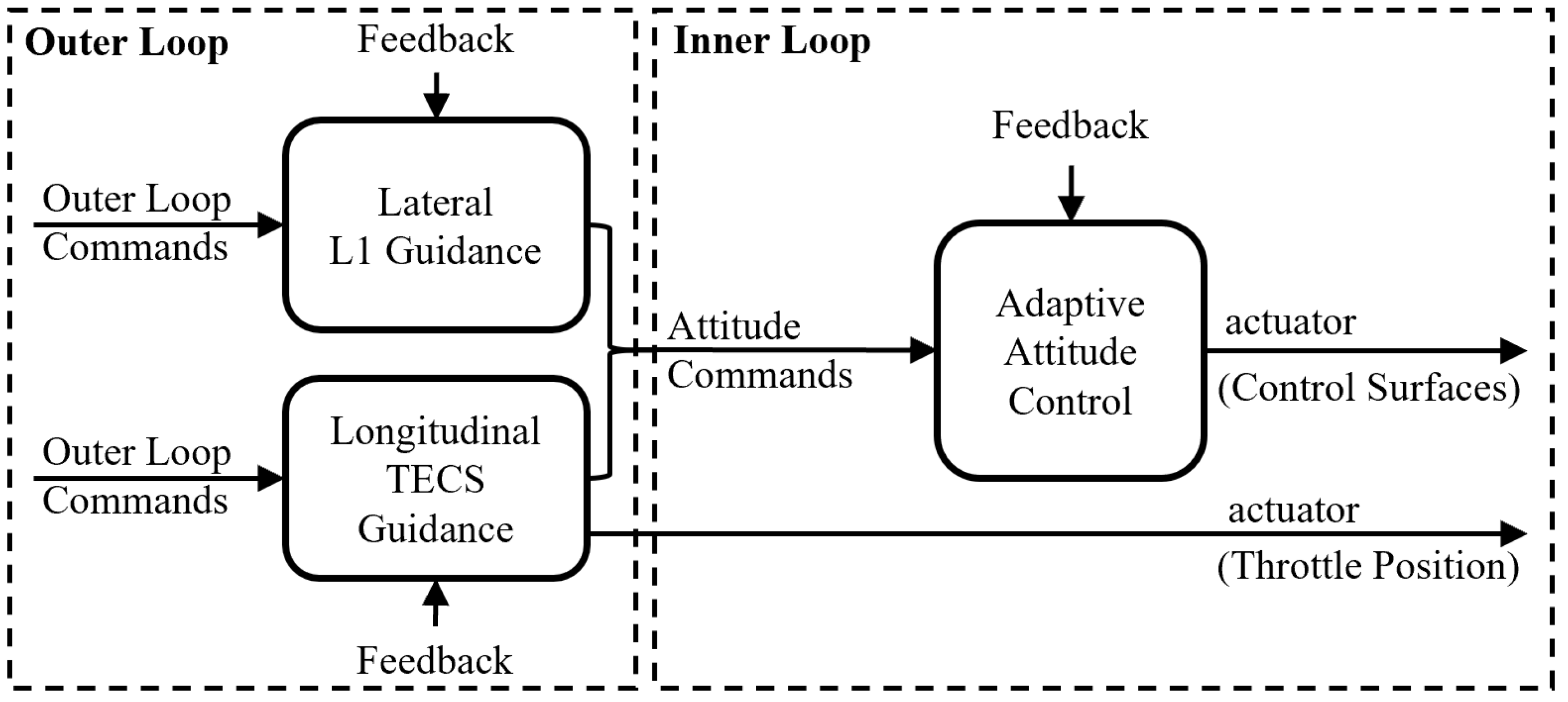
The control system structure, as shown in Figure 2, follows an inner–outer loop control structure. The outer loop is responsible for trajectory tracking control, converting the flight mission into attitude commands, and the inner loop, designated as attitude control, determines the deflection of each control surface, thereby enabling the UAV to follow the preset route.
The outer loop control system can be divided into longitudinal and lateral segments, where the longitudinal control uses the Total Energy Control System (TECS) [29] to calculate the desired pitch angle and throttle settings, and the lateral control employs L1 guidance [30]. Overall, energy control achieves decoupling control by reconstructing the relationship between the elevator and throttle actuators with altitude and speed. The inner loop focuses on attitude tracking, and issues such as modeling errors and parameter uncertainties need to be addressed at this stage. Based on the OLAC system, the attitude control systems for both longitudinal and lateral models are designed separately.

3.2. OLAC for Attitude Control

Introducing uncertainties into Equation (3) leads to
x ˙ = A x + B ( u + υ ( x ) ) ,
where υ ( x ) represents the matching uncertainty, which is defined as a linear combination of uncertain parameters Γ and regression vector Φ ( x ) , i.e., υ ( x ) Γ T Φ ( x ) .
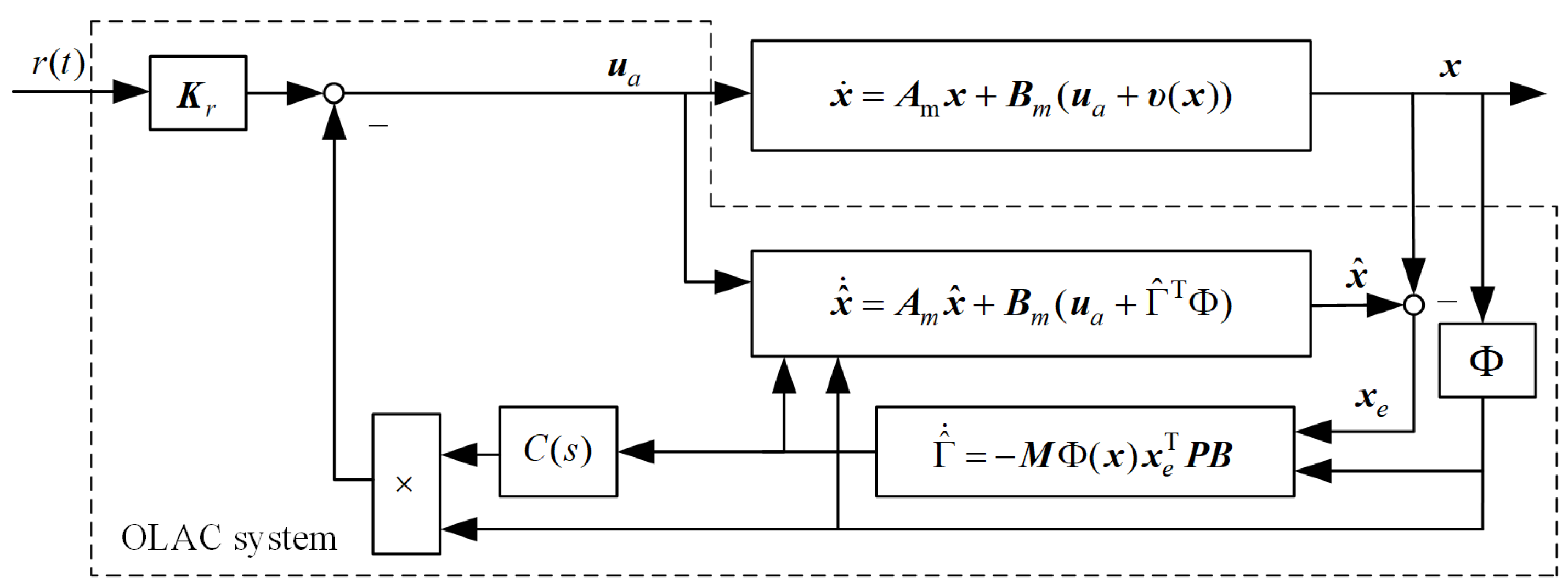
The structure diagram of the OLAC system is illustrated in Figure 3.
Considering the basic control law u b described in Equation (10) as
u b = K m x + K r r ,
where Km is the basic feedback gain, Kr is the feedforward gain of the basic controller, and r is the reference input.
If the desired system is designed as
x ˙ m = A m x m + B m r ,
where Am and Bm are the state matrix and input matrix, representing the desired dynamic and tracking performance.
By substituting Equation (11) into (3) and comparing it with Equation (12), the basic control gain should satisfy the following:
B K r = B m ,   and   A B K m = A m .
Remark 1.
The basic control gain can be derived from Equation (13). In flight control engineering, pole placement and LQR methods are commonly used for the feedback control design of SISO systems and MIMO systems, respectively.
The design of the adaptive control law is constructed based on the closed-loop system formed by the basic control law. Combining Equations (10) to (13), the state observer can be designed as follows:
x ^ ˙ = A m x ^ + B m ( u a + Γ ^ T Φ ) ,
where x ^ is the observed state variable, u a is the adaptive control law, and Γ ^ is the estimate of the uncertain parameter Γ.
Under the basic control law Equation (11), the closed-loop system of Equation (10) can be described as follows:
x ˙ = A m x + B m ( u a + υ ( x ) ) ,
where the error dynamics can be computed by subtracting Equation (14) from Equation (15), as shown:
x ˙ e = A m x e + B m Γ ˜ T Φ ,
where x e x ^ x is the state estimation error and Γ ˜ Γ ^ Γ is the parameters estimation error.
Based on the Lyapunov stability theorem, the adaptation law can be derived as
Γ ^ ˙ = Μ Φ ( x ) x e T P B ,
where M is the learning rate matrix and P = P T > 0 is the unique positive solution to the algebraic Lyapunov equation A m T P + P A m = I .
Considering the out-of-loop filter C ( s ) [25], the adaptive law can be formulated as
u a = η Φ ( x ) ,
where the Laplace transform η ( t ) is defined as η ( s ) C ( s ) Γ ^ T , and C ( s ) is a strictly proper function with bounded-input/bounded-output stability (BIBO) and a steady-state gain of 1.
Finally, the attitude control law consists of the basic feedback control law and adaptive control law, i.e.,
u = u b + u a .
Combining the longitudinal and lateral state space equations described in Equations (1) and (2), the attitude control based on OLAC can be effectively implemented.
Remark 2.
The uniformly bounded and asymptotically stability of the state estimation error xe following the adaptation law described in Equation (17) is proven in [25].

3.3. Outer Loop Control

3.3.1. Longitudinal TECS Guidance

The total energy E of the aircraft is regulated by throttle opening as follows:
Δ E = V c 2 V 2 2 g + ( H c H ) ,
δ T = k E δ T ( k P E Δ E + k I E Δ E d t ) ,
where V and H are the speed and height, the subscript “c” represents the commands, k E δ T is the gain from E to throttle opening, and k P E and k I E are the proportional and integral gains, respectively.
The total energy distribution L is controlled by the pitch angle as follows:
Δ L = ( 2 k w ) ( H c H ) k w ( V c 2 V 2 ) 2 g ,
θ c = k L θ ( k P L Δ L + k I L Δ L d t ) ,
where k w is the weight coefficient of the kinetic energy term, ranging from 0 to 2, k L θ is the gain from L to throttle opening, and k P L and k I L are the proportional and integral gains, respectively.

3.3.2. Lateral L1 Guidance

The L1 guidance law can be described as
φ c = k φ P ( Z Z c ) + k φ D ( ψ ψ c ) ,
where k φ P and k φ D are the feedback gains for lateral deviation and yaw angle, and Z and Ψ are the lateral deviation and yaw angle, respectively. If the chosen setting time is ts, then the gain values are k φ P = 4 π 2 / ( g t s 2 ) and k φ D = 2 2 π V / ( g t s ) .

4. Results

4.1. Configure for Simulation

Given the weight of the demonstration aircraft is 400 kg, the maximum sink rate is −3 m/s, the maximum touchdown pitch angle is 13.5°, and the maximum touchdown speed is 66.7 m/s, with an initial pitch angle of 5°. Based on the comprehensive analysis, the parameters for the flare gliding of the landing trajectory can be designed as V t g = 55   m / s , γ t s = 2 , H t s = 25   m , V t s = 6 5   m / s , and for the steep gliding γ t d = 3.5 , H t 0 = 1225   m .
In this section, the equilibrium points are selected as H * = 3000   m , V * = 0 . 4   Ma , γ * = 3 , and θ * = 0.78 , and the longitudinal and lateral characteristics are shown in Table 1 and Table 2. The desired dynamics for the longitudinal attitude system are ω n = 6 rad / s and ζ = 1.1 as standard second-order system. The LQR control is employed to design the basic controller for the lateral attitude system, with Q = diag ( 1 , 1 , 1 , 30 , 30 ) and R = diag 0.5 , 0.5 . The adaptive parameters are set as Μ = I , with C ( s ) representing a first-order low-pass filter with a cutoff frequency of 5 rad/s and a sampling time of 0.01 s. The parameters for TECS are k E δ T = 0.05 , k P E = 0.15 , k I E = 0.10 , k w = 0.70 , k L θ = 0.01 , k P L = 0.15 , and k I L = 0.15 , and for L1 guidance are k φ P = 0.18 , and k φ D = 2.85 .

4.2. Robustness Analysis

Based on the frequency domain analysis of linear systems, this paper proposes an equivalent analysis method to quantify the stability margin of adaptive control systems with nonlinear characteristics. Describing the nonlinear part of the adaptive control as a function Γ(x), which corresponds to Equation (15) in this paper, the dimension n of Γ and its range Θ(Γ) are established based on the stability requirements. Then, by selecting a grid step d, the parameter Γ is discretized within Θ(Γ) to generate a set Ω. An n-dimensional coordinate system is set up with parameter Γ as the axis, and an n-dimensional spatial grid is constructed based on set Ω, where each system at a single grid is considered a linear system. The stability margin at each grid can be calculated using methods for linear systems [31]. Ultimately, the stability margin set of the nonlinear system is the collection of figures for linear systems within set Ω.
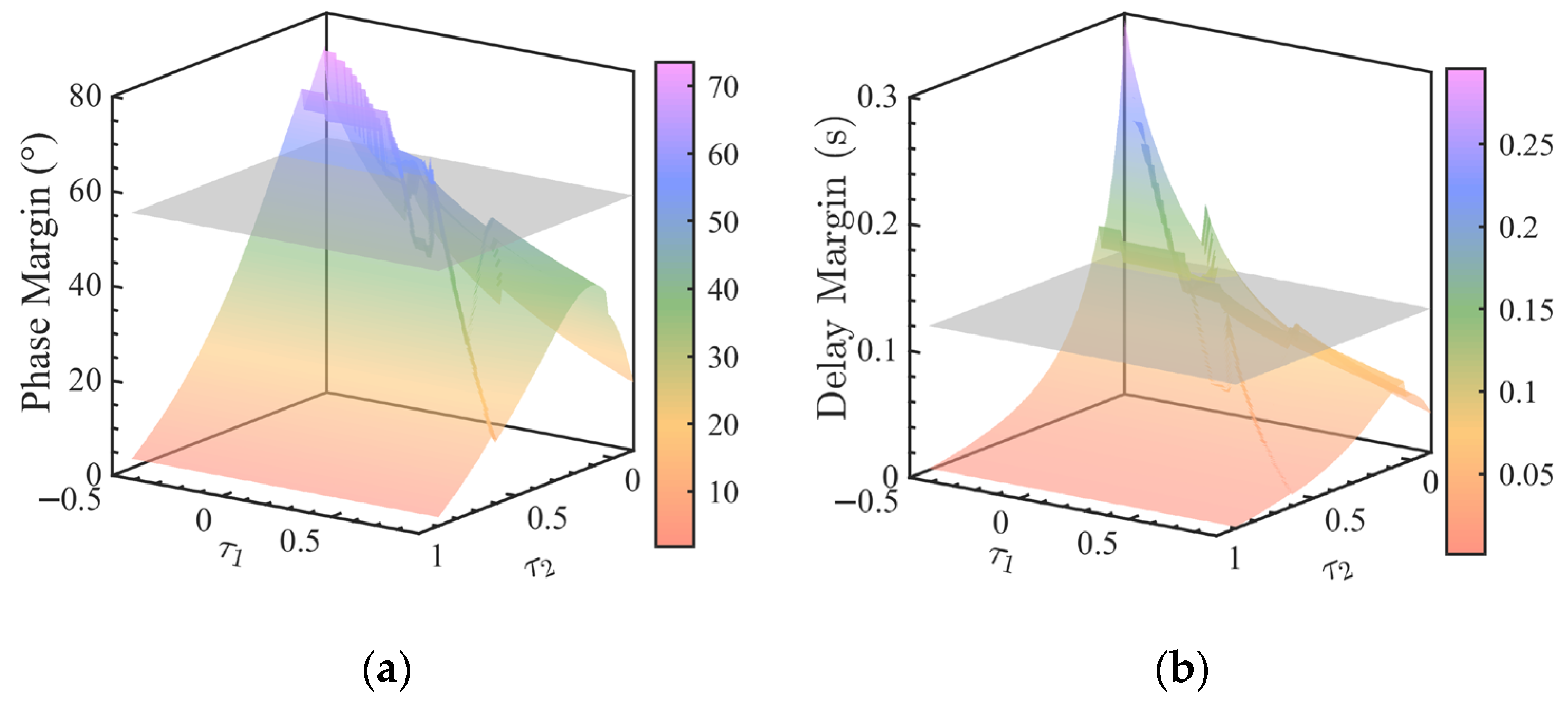
For instance, in the case of attitude control for the longitudinal system, with n = 2 and d = 0.01, Figure 4 shows the trend of stability margin as the parameter Γ varies. As a comparison, the results of the baseline controller are given with gray surfaces in Figure 4, which is parallel to the x-y plane. The z-axis range illustrates the maximum stability margin achievable as the parameter changes, offering insights into the adaptation to adjust closed-loop performance. The curvature of the surface reflects the system’s sensitivity to changes in nonlinear parameters, providing an intuitive grasp of the efficiency of adaptive parameters. Based on this, the stability margin analysis of the nonlinear adaptive system is realized. Therefore, it can be considered that the baseline method does not have the ability to adjust the stability margin of the system, while the designed adaptive control system effectively adjusts the dynamic performance of the system with great sensitivity, exhibiting strong robustness.

4.3. Time–Domain Simulation Verification

In this section, considering the uncertain parameter deviations shown in Table 3, robustness verification through the Monte–Carlo simulation is conducted. To determine the impact of each parameter on the control performance, time domain simulation is completed separately using the control variate method, and the corresponding error bars of the touchdown index are shown in Figure 5.
Figure 5 demonstrates the strong robustness of the designed landing control system, with all indicators meeting the design requirements. Specifically, variations in the lift coefficient, drag coefficient, and weight have notable effects on the index. Notably, speed and sink rate exhibit sensitivity to wind disturbances.
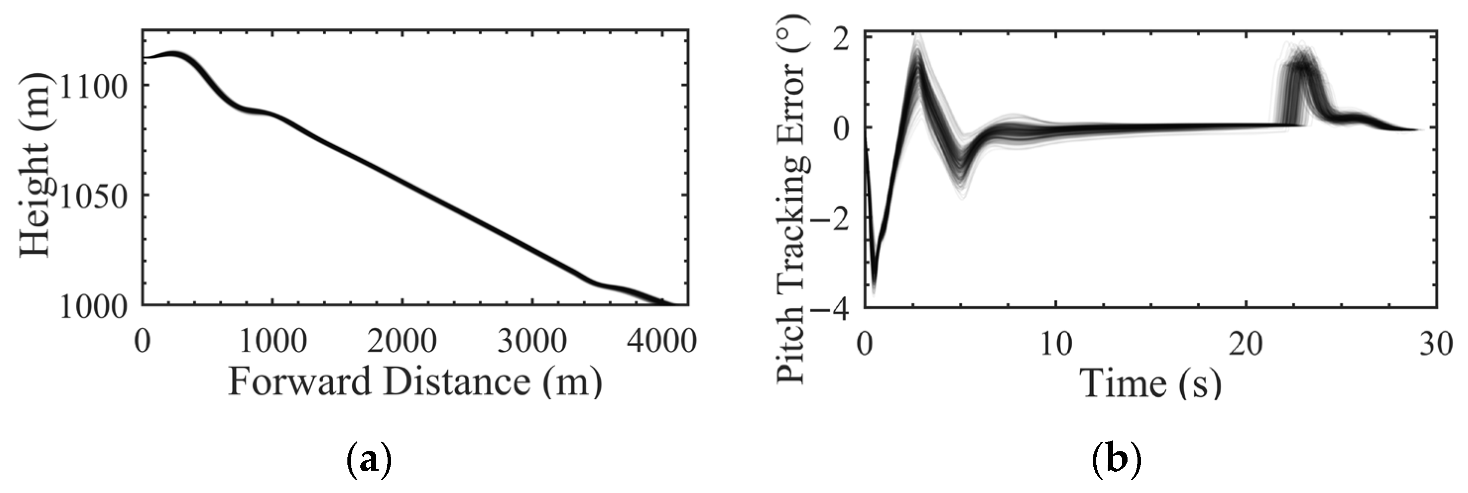
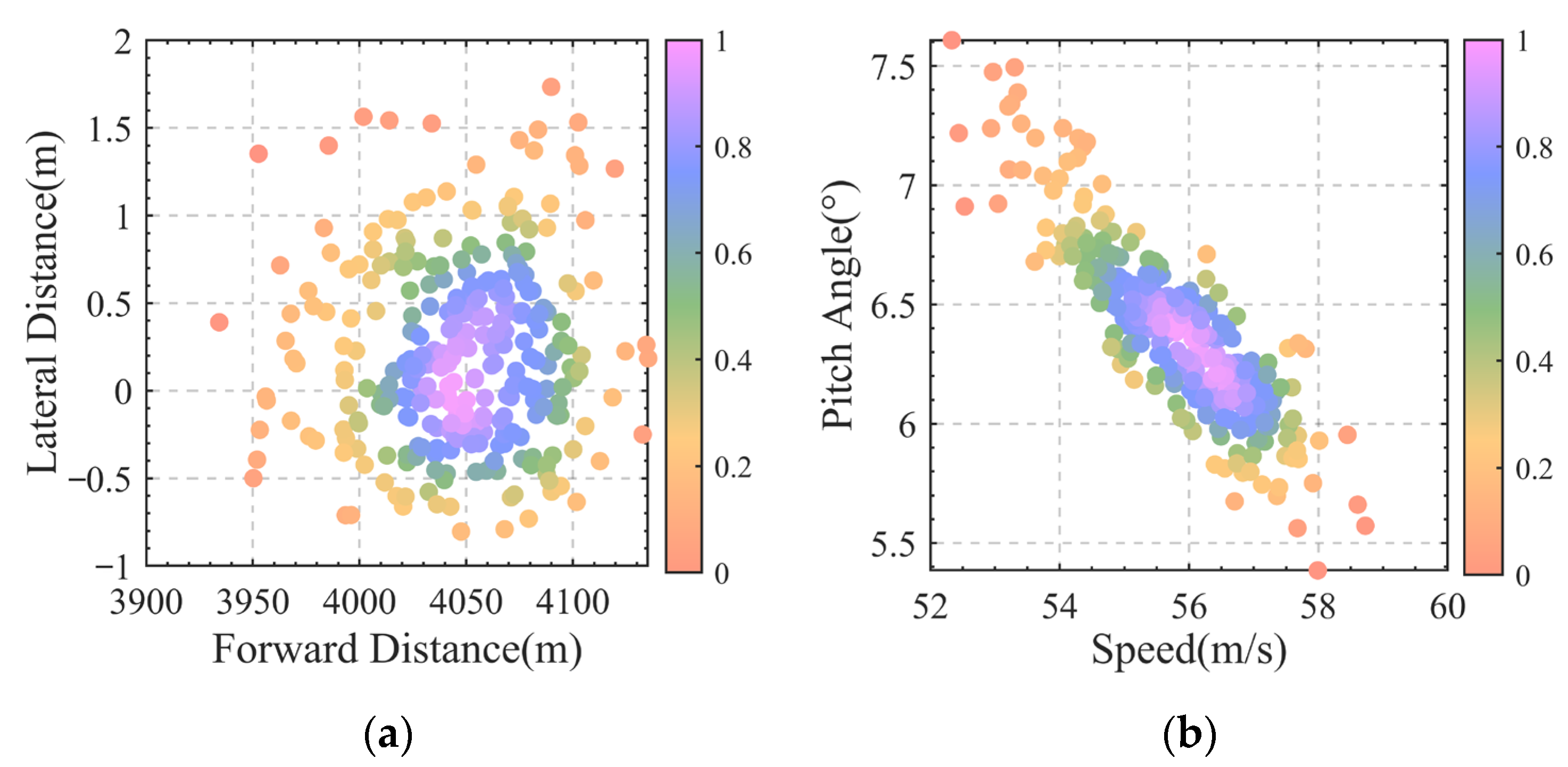
Monte–Carlo simulations were conducted according to the parameter ranges specified in Table 3, with 300 simulation runs and parameters following a normal distribution. The time–domain simulation results are shown in Figure 6 and Figure 7, and the landing index analysis is presented in Table 4.
Based on Figure 6 and Figure 7, it can be seen that the attitude of the aircraft remains relatively stable, and the tracking performance of height and speed meets the requirements among the 300 simulation runs. In Figure 6, the density can be assessed through variations in color intensity, allowing for a clearer understanding of the overlap between lines. The distribution of the touchdown index exhibits a fundamental Gaussian pattern. Combined with Table 4, it can be concluded that the variables at the landing point are consistent with the design values, staying within the specified constraints.
Overall, the designed control strategy demonstrates robustness, showcasing the ability to maintain the desired control performance even in the face of parameter uncertainties, thereby validating the efficacy of the OLAC-based landing control approach.

5. Conclusions

Targeting issues such as strong constraints and complex uncertainties in the autonomous landing process of high-speed UAVs, an accurate guidance and control method with strong engineering practicability based on the steep-flare gliding trajectory is proposed in this paper.
Theoretically, an OLAC system applicable to MIMO systems is proposed based on an LQR controller, where the controlled object is extended from the transfer function to the state–space function, addressing the challenging coupling control problem of the UAV attitude mode. It can be seen from the Monte–Carlo simulation results of the verification aircraft that the proposed OLAC system possesses sufficient robustness and the ability to ensure accurate tracking under uncertainties. From the practical perspective, this paper presents an engineering practical equivalent analysis method for the stability margin of the nonlinear control system, which is capable of a quantitative assessment of the robustness of systems with nonlinear and time-varying characteristics.
Overall, this paper presents an innovative adaptive attitude control for autonomous landings. The adaptive control method proposed in this paper is not limited to a specific type of UAV. By combining TECS and L1 guidance, precise control is achieved, and the effectiveness and reliability of the proposed landing strategy are demonstrated through the time-domain and frequency-domain simulation results. The nonlinearity and adaptability of the OLAC system provide the possibility for its application in diverse aviation scenarios, highlighting its potential for enhancing the safety and accuracy of aircraft landing. Future research will focus on unmatched uncertainties and investigate corresponding adaptive control structures. Additionally, based on this research, we aim to conduct flight experiments to validate the effectiveness of the algorithms.

Author Contributions

Conceptualization, Y.F., Q.H. and L.W.; methodology, Y.F., Q.H. and L.W.; validation, Y.F. and Q.H.; formal analysis, Q.H. and W.W.; investigation, Y.F. and H.Z.; resources, L.W.; data curation, L.W. and Q.G.; writing—original draft preparation, Y.F.; writing—review and editing, Y.F., Q.H. and W.W.; visualization, Q.H., W.W. and Q.G.; supervision, Y.F. and H.Z.; project administration, L.W.; funding acquisition, L.W and H.Z. All authors have read and agreed to the published version of the manuscript.

Funding

This research received no external funding.

Data Availability Statement

The data that support the findings of this study are available from the corresponding author upon reasonable request.

Acknowledgments

The authors acknowledge the support of the 1912 Project.

Conflicts of Interest

The authors declare no conflicts of interest.

References

  1. Liu, Z.T.; Gao, C.S.; Jing, W.X. Dynamic analysis and coupling control of underactuated flight vehicles with single moving mass. Aerosp. Sci. Technol. 2021, 116, 106854. [Google Scholar] [CrossRef]
  2. Efremov, A.V.; Efremov, E.V.; Tiaglik, M.S.; Irgaleev, I.K.; Shcherbakov, A.I.; Mbikayi, Z. Adaptive flight control system for flight safety improvement in reentry and other high-velocity vehicles. Acta Astronaut. 2023, 204, 900–911. [Google Scholar] [CrossRef]
  3. Barber, H.; Wall, A.; Larose, G.L.; Schajnoha, S. RPAS operations in urban airflow: Efficient modelling of representative wind speed variations along a flight path through a flow field with changing turbulence characteristics. J. Wind Eng. Ind. Aerodyn. 2024, 247, 105702. [Google Scholar] [CrossRef]
  4. Wang, L.; Liang, Y. Statistical analysis on global civil aviation accident investigation data. China Transp. Rev. 2021, 43, 7–12. [Google Scholar]
  5. Wang, L.; Ren, Y.; Wu, C.X. Effects of flare operation on landing safety: A study based on ANOVA of real flight data. Saf. Sci. 2018, 102, 14–25. [Google Scholar] [CrossRef]
  6. Meng, S.; Xiang, J.; Luo, Z.; Ren, Y.; Zhuang, N. A novel trajectory planning strategy for aircraft emergency landing using Gauss pseudospectral method. Control Theory Technol. 2014, 12, 393–401. [Google Scholar] [CrossRef]
  7. Zhang, H.; Guo, Z.; Sun, Z. Vertical control technology of autonomous landing of high-speed UAVs. J. Nanjing Univ. Aeronaut. Astronaut. 2020, 52, 881–888. [Google Scholar] [CrossRef]
  8. Lambregts, A. Avoiding the pitfalls in automatic landing control system design. In Proceedings of the Guidance and Control Conference, San Diego, CA, USA, 9–11 August 1982; p. 1599. [Google Scholar]
  9. Åström, K.J. Adaptive control. In Mathematical System Theory: The Influence of RE Kalman; Springer: Berlin/Heidelberg, Germany, 1995; pp. 437–450. [Google Scholar]
  10. Whitaker, H.; Kezer, A. Model reference adaptive systems to improve reliability. In Guidance and Control; Elsevier: Amsterdam, The Netherlands, 1962; pp. 499–522. [Google Scholar]
  11. Chen, Y.; Pérez-Arancibia, N.O. Adaptive control of a VTOL uncrewed aerial vehicle for high-performance aerobatic flight. Automatica 2024, 159, 109922. [Google Scholar] [CrossRef]
  12. Hovakimyan, N.; Cao, C. L1 Adaptive Control Theory: Guaranteed Robustness with Fast Adaptation; SIAM: Philadelphia, PA, USA, 2010. [Google Scholar]
  13. Ackerman, K.; Puig-Navarro, J.; Hovakimyan, N.; Cotting, M.C.; Duke, D.J.; Carrera, M.J.; McCaskey, N.C.; Esposito, D.; Peterson, J.M.; Tellefsen, J.R. Recovery of desired flying characteristics with an L1 adaptive control law: Flight test results on Calspan’s VSS Learjet. In Proceedings of the AIAA Scitech 2019 Forum, San Diego, CA, USA, 7–11 January 2019; p. 1084. [Google Scholar]
  14. Calise, A.J.; Yucelen, T. Adaptive loop transfer recovery. J. Guid. Control Dyn. 2012, 35, 807–815. [Google Scholar] [CrossRef]
  15. Singh, L.; Miotto, P.; Breger, L.S. L1 adaptive control design for improved handling of the F/A-18 class of aircraft. In Proceedings of the AIAA Guidance, Navigation and Control (GNC) Conference, Boston, MA, USA, 19–22 August 2013; p. 5236. [Google Scholar]
  16. Nguyen, N.; Krishnakumar, K.; Kaneshige, J.; Nespeca, P. Flight dynamics and hybrid adaptive control of damaged aircraft. J. Guid. Control Dyn. 2008, 31, 751–764. [Google Scholar] [CrossRef]
  17. Snyder, S.; Zhao, P.; Hovakimyan, N. Adaptive control for linear parameter-varying systems with application to a VTOL aircraft. Aerosp. Sci. Technol. 2021, 112, 106621. [Google Scholar] [CrossRef]
  18. Feng, Y.; Sun, Z.H.; Wu, L.N.; Wang, Y.S.; Xi, B.; Ho, W.K.; You, Y.C. Nonlinear adaptive flight control system: Performance enhancement and validation. Chin. J. Aeronaut. 2023, 36, 354–365. [Google Scholar] [CrossRef]
  19. He, X.K.; Wu, J.D.; Huang, Z.Y.; Hu, Z.X.; Wang, J.; Sangiovanni-Vincentelli, A.; Lv, C. Fear-Neuro-Inspired Reinforcement Learning for Safe Autonomous Driving. IEEE Trans. Pattern Anal. Mach. Intell. 2024, 46, 267–279. [Google Scholar] [CrossRef]
  20. Niu, C.; Yan, X.T.; Chen, B.Y. Control-oriented modeling of a high-aspect-ratio flying wing with coupled flight dynamics. Chin. J. Aeronaut. 2023, 36, 409–422. [Google Scholar] [CrossRef]
  21. Duan, X.B.; Cong, J.Q.; Dai, Z.Z.; Cheng, J.H.; Zhang, X.; Jing, J.P. Influence mechanism and quantificational evaluation of key factors affecting flutter stability of a transonic fan. Aerosp. Sci. Technol. 2023, 138, 108312. [Google Scholar] [CrossRef]
  22. He, X.K.; Huang, W.H.; Lv, C. Toward Trustworthy Decision-Making for Autonomous Vehicles: A Robust Reinforcement Learning Approach with Safety Guarantees. Engineering 2024, 33, 77–89. [Google Scholar] [CrossRef]
  23. He, X.K.; Huang, W.H.; Lv, C. Trustworthy autonomous driving via defense-aware robust reinforcement learning against worst-case observational perturbations. Transp. Res. Part C-Emerg. Technol. 2024, 163, 104632. [Google Scholar] [CrossRef]
  24. Das, S.S.; Shtessel, Y.; Zhang, C.; Plestan, F. Definition and analysis of stability margins for a class of nonlinear systems. Int. J. Robust Nonlinear Control 2022, 32, 1055–1074. [Google Scholar] [CrossRef]
  25. Das, S.S.; Shtessel, Y.; Plestan, F. Phase and gain stability margins for a class of nonlinear systems. IFAC-PapersOnLine 2018, 51, 263–268. [Google Scholar] [CrossRef]
  26. Beard, R.W.; McLain, T.W. Small Unmanned Aircraft: Theory and Practice; Princeton University Press: Princeton, NJ, USA, 2012. [Google Scholar]
  27. Stevens, B.L.; Lewis, F.L.; Johnson, E.N. Aircraft Control and Simulation: Dynamics, Controls Design, and Autonomous Systems; John Wiley & Sons: Hoboken, NJ, USA, 2015. [Google Scholar]
  28. Chen, B.Y.; Chen, J.B.; Liu, Y.B.; Lei, H.; Jia, S. Guardian maps based robust stability analysis with applications in flight control of hypersonic vehicles. Aerosp. Sci. Technol. 2020, 106, 106208. [Google Scholar] [CrossRef]
  29. Zhang, Q.-Z.; An, T.-W. A new method for designing decoupling controller of flight speed/flight path based on total energy control. Acta Aeronaut. Astronaut. Sin. 2004, 25, 389–392. [Google Scholar]
  30. Park, S.; Deyst, J.; How, J. A new nonlinear guidance logic for trajectory tracking. In Proceedings of the AIAA Guidance, Navigation, and Control Conference and Exhibit, Providence, RI, USA, 16–19 August 2004; p. 4900. [Google Scholar]
  31. Van Drongelen, W. Signal Processing for Neuroscientists; Academic Press: Cambridge, MA, USA, 2018. [Google Scholar]
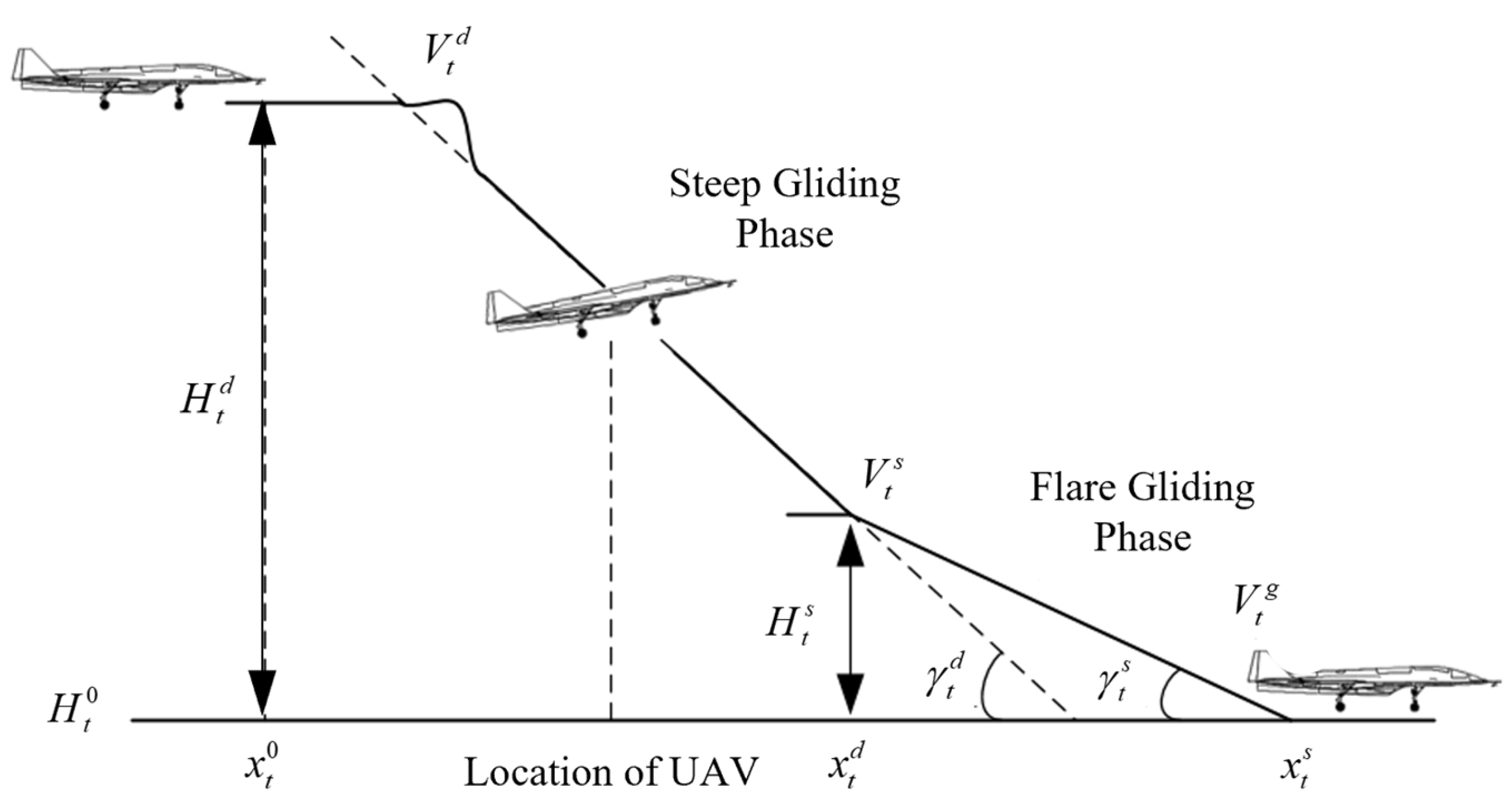
Figure 1. UAV automatic landing contrail.
Drones 08 00587 g001
Figure 2. Control structure for autonomous landing.
Drones 08 00587 g002
Figure 3. Structure of the OLAC system.
Drones 08 00587 g003
Figure 4. The impact of adaptive parameters on stability margin. (a) Phase Margin, (b) Delay Margin.
Drones 08 00587 g004
Figure 5. Error bars for the touchdown index under single parameter deviation. (a) Speed, (b) Pitch Angle, (c) Forward Distance, (d) Sink Rate.
Drones 08 00587 g005
Figure 6. Time-domain curves for Monte–Carlo simulation. (a) Height-Forward Distance, (b) Pitch Tracking Error, (c) Speed, (d) Sink Rate.
Drones 08 00587 g006aDrones 08 00587 g006b
Figure 7. Density map of landing index for Monte–Carlo simulation. (a) Landing Point, (b) Speed-Pitch Angle.
Drones 08 00587 g007
Table 1. Longitudinal Attitude Characteristics.
ModalEigenvalueDampingPeriod (s)
Phugoid mode−0.0112 ± 0.106 i0.10458.7
Short-period mode−1.26 ± 2.36 i0.4702.35
Table 2. Lateral–Directional Attitude Characteristics.
Spiral-Divergence Time Constant (s)Roll Time Constant (s)Dutch-Roll Mode
EigenvalueDampingPeriod (s)
−48.50.535−0.738 ± 7.70 i0.1031.26
Table 3. Range of Uncertainty.
ParametersNumberRange
Lift coefficient1±10%
Drag coefficient2±10%
Pitch moment3±10%
Control surface efficiency4±10%
Dynamic derivative5±50%
Moment of inertia6±20%
Wind speed7±5 m/s
Thrust angle8±1°
Distance from thrust to the gravity center9±0.05 m
Center of gravity10±0.01 m
Weight11±30 kg
Table 4. Landing Index Analysis.
IndicatorsSpeed (m/s)Pitch Angle (°)Sink Rate (m/s)Distance (m)
Range52.3~58.75.4~10.2−2.1~−1.93934~4135
Mean55.87.8−2.04047
Disclaimer/Publisher’s Note: The statements, opinions and data contained in all publications are solely those of the individual author(s) and contributor(s) and not of MDPI and/or the editor(s). MDPI and/or the editor(s) disclaim responsibility for any injury to people or property resulting from any ideas, methods, instructions or products referred to in the content.