Abstract
When LoRaWAN networks are deployed in complex environments with buildings, jungles, and other obstacles, the communication range of LoRa signals experiences a notable reduction, primarily due to multipath propagation, fading, and interference. With the flight advantage of height, mobility, and flexibility, UAV can provide line-of-sight (LOS) communication or more reliable communication in many scenarios, which can be used to enhance the LoRaWAN network’s performance. In this paper, a novel UAV-assisted LoRaWAN network is designed and implemented. Specifically, a UAV-assisted LoRaWAN network system architecture is proposed to improve the LoRaWAN network coverage and communication reliability, in which the UAV architecture of “UAV + Remote Controller + Server” is combined with the traditional LoRaWAN architecture of “End-Device + Gateway + Server”. Then, the implementation of the UAV gateway and the remote controller relay is presented, which play the important role of forwarding LoRaWAN frames transparently in our proposed architecture. In detail, the UAV gateway is developed based on the UAV’s PSDK and classical LoRa packet forwarder, and the remote controller relay is developed based on UAV’s MSDK. The experimental results show that the network coverage and communication reliability of our proposed LoRaWAN network have been significantly improved, effectively supporting a wide range of LoRaWAN applications. Specifically, when the end-device is deployed 1.3 km away with numerous obstacles in the propagation environment, with the UAV altitude advantage and the remote controller’s relay capability, the proposed system achieved an SNR of 5 db and an RSSI of −80 dbm with a packet loss rate of 3%. In comparison, the ground gateway only achieved an SNR of −16 db and an RSSI of −113 dbm with a packet loss rate of 73%.
1. Introduction
1.1. Background and Significance
Nowadays, LoRa technology, with its unique low-power and long-range capabilities, has become the globally leading LPWAN technology. A 2024 Omdia Research report indicates that more than 30% of LPWAN connections worldwide use LoRa technology [1]. A convenient solution for the deploying of LoRa devices is provided by the LoRaWAN specification, facilitating the widespread application of LoRa in areas such as environmental monitoring [2], agriculture automation [3], smart cities [4,5], health care and medicine [6,7], etc. However, in scenarios such as underground sensor networks, forest monitoring, and search and rescue (SaR), the network performance was limited by the traditional ground LoRaWAN gateway. When the LoRaWAN network is deployed in these complex environments with numerous obstacles, it is faced with the problem of increased path loss causing a rapid decrease in network coverage and communication reliability [8,9,10,11]. For instance, the experimental results of Ferreira et al. in PARNASO and Lille shows that the longest propagation distance of LoRa signal has been sharply reduced in forests and high-density urban areas [12]. With transmission power of 14 dbm and the maximum spread spectrum factor, the longest propagation distance of LoRa signals in forests and high-density urban areas is only 250 m and 208 m, respectively. Similar conclusions were also reached by Villarim et al. in Brazil and Portugal [13]. Numerous real-world experiments have shown that the longest propagation distance of LoRa in a complex environment is considerably lower than the theoretical expectation of 15 km for suburban and 5 km for urban areas. Therefore, how to enhance the LoRaWAN network capabilities such as network coverage and communication reliability in complex environments with numerous obstacles is arousing more and more interest from researchers.
With the rapid development of unmanned aerial vehicle (UAV) technology, the concept of UAV-assisted wireless communication has been proposed to improve the network coverage, cost efficiency, and scalability [14,15,16]. Specifically, when the UAV is applied in a LoRaWAN network, the coverage, reliability, and energy efficiency of the LoRaWAN network are significantly improved, while facilitating the deployment of LoRaWAN network in various scenarios. First, the line-of-sight (LoS) connectivity characteristic of UAV avoids the interference and fading caused by obstacles, effectively improving the coverage and reliability of the LoRaWAN network [17,18,19]. In addition, the mobility of the UAV reduces the communication distance between the LoRaWAN end-devices and gateways. Therefore, lower transmission power and spreading factor (SF) can be applied by a wide range of LoRaWAN end-devices, reducing the LoRaWAN network energy consumption [20,21]. At the same time, the UAVs can be deployed flexibly and on demand, facilitating diverse applications of LoRaWAN networks. On the one hand, UAVs can serve as temporary base stations in scenarios such as search and rescue (SaR) [22], emergency temporary networks [23], and positioning scenarios [24]. On the other hand, UAVs provide the possibility for deploying LoRaWAN networks in harsh environments and unconnected remote areas [25,26]. Therefore, the UAV-assisted LoRa network has attracted significant attention from researchers.
1.2. Literature Review
By reviewing and comparatively analyzing the exiting works, the integration of LoRa and UAV was divided into two categories: UAV-assisted LoRa network without LoRaWAN specification and UAV-assisted LoRaWAN network. Moreover, the UAV-assisted LoRaWAN network can be further divided into two types: UAV carrying end-device as the payload and UAV carrying gateway as the payload.
1.2.1. UAV-Assisted LoRa Network without LoRaWAN Specification
Trasvina-Moreno et al. proposed a remote marine environmental monitoring system based on UAVs and a wireless sensor network (WSN) [27]. The proprietary network layer protocol called LoRaNET was developed for this specific project. In the protocol, sensors serve as secondary nodes to measure environmental parameters, while UAVs serve as network managers and collect data from sensors. LoRa communication is adopted by the protocol to realize an ultra-low power WSN network. Similarly, Vlasceanu et al. proposed a hybrid UAV-WSN system for precision agriculture [28]. In this work, the ground base station and LoRa end-devices within its coverage form a sub-WSN network, which uploads the collected senser data to the UAV through the nRF24L01+ module. The key-value protocol was utilized in both the sub-WSN network and the upload process. Holtorf et al. designed a LoRa-based UAV platform for underground sensor data collection [29]. LoRa is utilized for communication among underground sensor nodes, UAVs, and ground stations. The experimental results show that the maximum communication distance between the UAV and the underground sensor node can reach 550 m. Similarly, Cariou et al. developed the same system for underground data collection [30]. In this system, the communication between UAVs and base stations was replaced by 2.4 GHz ZigBee technology to achieve higher bit rates. Zhang et al. proposed a high-speed UAV data collection system combining 5 GHz and LoRa technology [31]. The UAV integrates both the LoRa and a 5 GHz module, where the LoRa functions as the wake-up signal to initiate high-speed 5 GHz transmission. The experimental results show that the system can reliably collect data with a throughput of 3.5 Mb/s when the UAV is located at an altitude of 140 m.
The above research confirms that the integration of UAVs and LoRa has broad application prospects in areas such as marine environment monitoring, precision agriculture, and wireless underground sensor networks. However, these studies are scattered and fragmented. On the one hand, various transmission protocols such as key-value and ZigBee and proprietary protocols like LoRaNET are adopted. On the other hand, various system architectures have been implemented. In some studies, UAVs serve as relay nodes, while in others they act as network centers. The lack of a standardized protocol and architecture obstructs the large-scale promotion and subsequent improvement of these system.
1.2.2. UAV-Assisted LoRaWAN Network
According to the payload carried by the UAV, the UAV-assisted LoRaWAN network can be further divided into two categories: (1) UAV carrying end-device as the payload and (2) UAV carrying gateway as the payload.
- UAV Carrying End-Device as the Payload
When the UAV is carrying an end-device as the payload, one of the most typical applications is air-quality monitoring. Chen et al. integrated multiple sensors and a LoRa transceiver into the UAV to implement an automated air quality monitoring platform [32]. A web interface was also designed for data visualization and collection configuration. Similarly, Camarillo-Escobedo et al. implemented an intelligent multi-sensor monitoring system with UAVs and LoRa [33]. Low-weight, compact, low-power designs are taken into consideration to optimize the monitoring system performance. Martinez-Caro et al. proposed a performance evaluation algorithm for the UAV-assisted LoRaWAN network [34]. With the background of a UAV carrying LoRaWAN end-device for air quality monitoring, the proposed algorithm is applied to evaluate eight different mobility models to verify its feasibility.
In certain scenarios, integrating LoRaWAN end-devices onto UAVs can enhance the information acquisition capabilities of end-devices. However, this scheme only improves the performance of a specific end-device and has limited benefits for the entire LoRaWAN network. Moreover, the number of end-devices can reach thousands in most LoRaWAN applications. Thus, it can be costly and inefficient to equip each end-device with a UAV. In contrast, deploying one or multiple UAVs to carry LoRaWAN gateways can significantly enhance the performance of LoRaWAN networks on a large scale, making it more suitable for most LoRaWAN applications.
- UAV Carrying Gateway as the Payload
Chen et al. integrated the mobility of a UAV with LoRa to minimize end-device energy consumption. Combining with UAV trajectory and transmission strategy optimization, a single UAV data collection system named LoRaDrone is proposed [35]. In the author’s subsequent work, the multi-gateway scenario is also considered [36]. A multi-gateway data collection system named MLoRaDrone is designed for a large-scale low-power LoRaWAN network. DeRango et al. designed an intelligent routing strategy for the UAV-based LoRaWAN network [37]. While collecting data, the UAV analyzes and learns the traffic flow to optimize the trajectory of the future activity. Ferreira et al. applied a series of bio-heuristic algorithms to optimize the position of UAVs in the array [38], effectively improving the coverage and capacity of the LoRaWAN network. In addition, Kirichek et al. introduced a flying ubiquitous sensor network (FUSN), providing a solution for the long-distance transmission of ground sensor data [39].
These studies have theoretically analyzed the optimization of the UAV-assisted LoRaWAN network. Valuable guidance is provided for improving network coverage, energy efficiency, and network capacity. However, in their hypothesis, the gateway always has a stable network connection on a UAV, which is difficult to achieve in most cases. Therefore, the communication implementation between gateways and the server should be considered carefully to ensure the network reliability.
Moheddine et al. integrated ground LoRaWAN gateways onto UAVs to expand the network coverage [40]. In this work, a LoRaWAN gateway that is constructed with a Raspberry Pi and a Rak2245Pi-cap board was carried on the UAV. The system was tested first in Wi-Fi and later in a cellular network with a long-term evolution (LTE) module. Almalki et al. implemented an intelligent agricultural monitoring platform with a UAV and LoRaWAN network [41]. In this work, the UAV is equipped with a LoRaWAN gateway, LG02, developed by Dragino, which accesses servers via a cellular connection. Similarly, Park et al. implemented a LoRa-based UAV platform for forestry monitoring [42]. Dragino’s LoRaWAN gateway called LG01 was carried on the UAV and connected to the server through Wi-Fi. Moreover, Delafontaine et al. utilized the mobility of UAVs to improve the positioning accuracy of LoRaWAN networks [43]. In this work, the Huawei E3372 USB modem is equipped on the gateway to provide a cellular connection. Behjati et al. designed an intelligent UAV system for livestock monitoring [44]. In this work, a SX1301-based multi-channel LoRaWAN gateway was carried on the UAV. To deal with the unstable network connection in airborne scenarios, a local mini-server was designed on the UAV for storing LoRa packets. The same architecture was applied in the authors’ previous studies [45]. Gallego-Madrid et al. proposed a novel LoRaWAN network architecture, which combined a LoRaWAN network with a UAV and multi-access edge computing (MEC) technology [46]. In the proposed architecture, the MEC layer is added between the gateway and the server to perform data preprocessing tasks. When the network is available, the data is uploaded to the LoRaWAN server by an MEC layer through Wi-Fi or LTE 4G. Otherwise, the data will be locally stored in the MEC layer until the network is restored.
In conclusion, there are two solutions available for the airborne LoRaWAN gateway to communicate with the server. The first solution is to equip the LoRaWAN gateway with a Wi-Fi or cellular module [27,28,29,30]. However, the coverage range of Wi-Fi is hard to support the movement range of UAVs. Moreover, the performance of the cellular network relies on the level of infrastructure development. As a result, this solution cannot guarantee reliable communication between the gateways and the server, especially when the UAV is deployed in remote areas with inadequate base station coverage. The other solution is to establish a local server on the UAV [31,32,33] for temporary data storage. However, this scheme restricts the real-time LoRaWAN applications such as forest monitoring, search and rescue, and positioning. In addition, the local server also requires additional computing and storage resources on the UAV.
1.3. Motivation and Contribution
The existing research on the integration of LoRa and UAV is summarized in Table 1. Numerous research works are carried out on the network construction (architecture, protocol, system workflow, etc.) and on the integration design of UAVs with a LoRa end-device or gateway. Most of the work focused on using UAVs to carry LoRaWAN gateways to expand LoRaWAN network coverage. In this way, the coverage, communication reliability, and flexibility of the entire LoRaWAN network can be improved with only a few UAVs.

Table 1.
Comparison and analysis of research on the integration of LoRa and UAV.
However, with the analysis of the typical implementations in [20,40,41,42,43,44,45,46], the existing research still has the following problems:
- The UAVs only serve as flight carriers, and their communication capabilities are not used to assist LoRaWAN networks.
- The altitude advantage of UAVs was leveraged to facilitate the deployment of LoRaWAN networks in complex environments. However, the integrated solution of “UAV + Remote Controller + Server”, which can enhance communication reliability and further expand the coverage of LoRaWAN network in an efficient way, was not considered.
- Information interaction between UAVs and LoRaWAN gateways was not realized, including transparent data forwarding, clock synchronization and GPS location acquisition, resulting in a limited application scalability of the existing UAV-assisted LoRaWAN network.
Therefore, this paper proposes a novel UAV-assisted LoRaWAN network to improve the coverage and communication reliability of a LoRaWAN network, facilitating wider applications of LoRaWAN networks. Different from the existing implements, both the communication and GPS capacity of UAVs has been utilized to construct a more feature-rich and powerful LoRaWAN network. In addition, with the integrated solution of “UAV + Remote Controller + Server”, the LoRaWAN gateway achieves stable communication with a server through a UAV link instead of Wi-Fi or cellular module. Moreover, the communication among the gateway, UAV, remote controller, and server was designed to follow LoRaWAN protocol, ensuring the scalability and portability of the system. The main contributions of this paper are summarized as follows, and a comparison with existing research is also included in Table 1.
- Based on the analysis of the specific requirements of the UAV-assisted LoRaWAN network system, a UAV-assisted LoRaWAN network system architecture is proposed, expanding the LoRaWAN network coverage through the integrated solution of “UAV + remote control + server” effectively.
- A LoRaWAN gateway prototype, which is highly integrated with the UAV, has been developed to enhance the LoRaWAN network through UAV altitude and line-of-sight advantages. Various UAV resources were provided to the LoRaWAN gateway through the multiple interfaces provided by a PSDK adapter board, including UART, PPS signal, and USB type-C. In addition, a forwarding program called the UAV packet forwarder was designed to manage the forwarding task and UAV resources.
- A relay solution based on remote controller was proposed to further extend the coverage of UAV. With the Wi-Fi or cellular network and UAV communication resources, a MSDK-based APP was developed to realize the relay features. Through the monitoring and transparent forwarding for both the UAV and LoRaWAN server, the coverage of the LoRaWAN network was effectively extended with a single relay.
- A performance evaluation and a positioning demonstration were carried out in the real world with the proposed network. The superiority of the UAV-assisted LoRaWAN network is verified in the typical LoRaWAN applications of both data collection and positioning.
The remainder of this paper is organized as follows. Section 2 introduces the construction of the LoRaWAN network and the basic concepts of the UAV payload development technology. Section 3 introduces the overall architecture of the UAV-assisted LoRaWAN system. Section 4 introduces the hardware and software implementation of the UAV gateway and the relay solution based on remote controller. Section 5 discusses experimental testing in real settings, including a coverage and communication reliability evaluation and a positioning demonstration. Section 6 summarizes the research results and discusses the future improvement directions.
2. LoRaWAN Network and UAV Payload Development Technology
2.1. LoRaWAN Network
LoRaWAN, as a low-power wide-area network protocol, has attracted wide attention from industry and academia. Various LoRaWAN solutions such as LoRa Edge, ThingPark, and the Cisco LoRaWAN platform have been implemented by numerous corporations, collectively building the vast LoRaWAN ecosystem. The LoRaWAN network adopts a single-hop star topology, consisting of LoRaWAN end-devices, LoRaWAN gateways, and LoRaWAN servers.
2.1.1. LoRaWAN End-Devices
Typically, a LoRaWAN end-device is composed of a LoRa transceiver, multiple sensors, a microcontroller (MCU), and an essential power module. The LoRaWAN end-device is responsible for collecting sensor data and generating RF LoRa or FSK packets. Due to the ultra-low power of LoRa, the life of a battery-powered end-device can reach 10 years. For different applications, LoRaWAN end-devices can be deployed on the ground, mounted on UAVs, or even buried underground or underwater.
2.1.2. LoRaWAN Gateway
A LoRaWAN gateway consists of a LoRa concentrator for detecting RF LoRa data packets, a host to manage data forwarding, and an optional GPS module. The gateway serves as a bridge between LoRaWAN end-devices and servers. On the one hand, the gateway processes RF LoRa packets at the physical layer. On the other hand, the gateway is connected to the LoRaWAN server through Wi-Fi, cellular networks, or the Ethernet, implementing the interaction with the server at the network layer.
Since there is no unified standard for the communication between the LoRaWAN gateway and the server, various gateway software implementations are applied in the existing LoRaWAN network. One of the most typical implementations is the LoRa packet forwarder, as shown in Figure 1. With the Semtech’s C language library, called Semtech HAL, the LoRa concentrator can be driven through an SPI interface for RF LoRa packet processing. On the other hand, a UDP connection was established by the LoRa packet forwarder to interact with the LoRaWAN server through the GWMP (LoRa gateway message protocol). Due to its long-standing history and ease of implementation, the LoRa packet forwarder has been widely used in the existing LoRaWAN gateways.
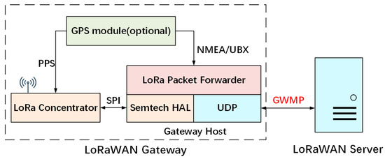
Figure 1.
LoRa Packet Forwarder architecture.
2.1.3. LoRaWAN Server
Typically, the LoRaWAN server includes a network server, application server, and join server. Among them, the network server is the key component of the server, which is responsible for critical tasks such as security, quality of service, and device management. One of the most popular open-source LoRaWAN network servers is ChirpStack. It is worth mentioning that the LoRaWAN network server of Cisco’s positioning system is exactly that: ChirpStack.
The ChirpStack server supports various gateway implementations and offers flexible extension methods. It is mainly composed of (1) the ChirpStack gateway bridge, (2) a MQTT broker, and (3) ChirpStack, as shown in Figure 2.
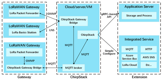
Figure 2.
Gateway compatibility and flexible extension of ChirpStack.
- ChirpStack Gateway Bridge
As described earlier, the LoRaWAN gateway software has a variety of implementations, such as LoRa packet forwarder, LoRa basic station, ChirpStack MQTT forwarder, etc. The ChirpStack gateway bridge component converts various protocols of different LoRaWAN gateway implementations into a standard format, including the GWMP protocol of the LoRa packet forwarder and the LNS (LoRaWAN network server) protocol of the LoRa basic station.
- MQTT broker
The MQTT broker component is responsible for forwarding data, commands, and other messages between the ChirpStack gateway bridge and ChirpStack. In addition, if a ChirpStack gateway bridge component has been installed on the gateway, the MQTT broker can communicate with the gateways directly through the MQTT protocol.
- ChirpStack
The ChirpStack component provides strong scalability for the server. On the one hand, numerous services, such as AWS SNS, LoRa Cloud, and Azure Service Bus are integrated into the ChirpStack. Therefore, various mature LoRaWAN solutions can be utilized with a simple configuration. On the other hand, a gRPC-based API is provided by ChirpStack for retrieving data from ChirpStack. The ChirpStack SDKs, which support multiple languages such as Go, Python, and JavaScript, are also officially developed for simplifying the API development.
2.2. UAV Payload Development Technology
Existing UAV-assisted LoRaWAN systems only utilize the mobility and altitude advantage of UAVs to improve the network coverage. However, various UAV resources such as power supply, communication, and payload capacity were not considered. To simplify the utilization of these resources, a variety of hardware and software tools were provided by DJI, including a PSDK (payload software development kit) and an MSDK (mobile software development kit).
2.2.1. Payload Software Development Kit (PSDK)
The PSDK mainly consists of a C/C++ library called PSDK Lib and a hardware platform called the PSDK adapter board. The PSDK Lib supports the Linux, ROS, and RTOS platforms and provides a series of interfaces for the utilization of UAV resources. Usually, the PSDK Lib should be used together with the PSDK adapter board. The PSDK adapter board converts the UAV-specific interface into various standard interfaces, including a UART for communication, a PPS signal for clock synchronization, a USB type-C interface for both power supply and communication, and a series of XT30 power supply interfaces, as shown in Figure 3.
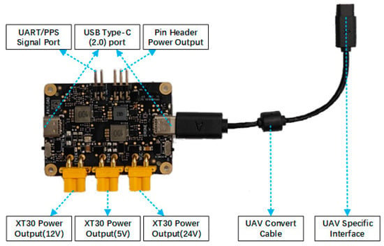
Figure 3.
Multiple interfaces provided by PSDK adaptor aboard.
With the hardware interfaces and software functions provided by the PSDK, the mainstream embedded platforms such as STM32 and Raspberry Pi can easily be integrated to the UAV. First, with the XT30 or USB type-C port provided by a PSDK adapter board, the user device can be powered through the UAV. Therefore, no additional power module is needed, reducing the weight and cost of UAV systems. In addition, wired communication between the user device and the UAV is established with UART and USB type-C ports, which are the basics of the integrated solution of “UAV + Remote Controller + Server”. Moreover, various UAV payload resources are available for the user device. For example, with the GPS resource of the UAV, user devices can acquire GPS location information and achieve clock synchronization through the PPS signal. Nowadays, various user devices such as loudspeakers, mapping cameras, and air-quality monitors have been developed based on the PSDK, effectively facilitating the application of UAVs.
2.2.2. Mobile Software Development Kit (MSDK)
The MSDK is a library that can be imported into Android applications, supporting both remote controller and Nexus devices, which is connected to the remote controller. Different from the PSDK, the MSDK provides similar UAV resources for a special device, the UAV remote controller. Specifically, with the wireless channel of the UAV, communication between the UAV and remote controller can be established by the MSDK. In addition, various UAV payload resources were also provided to the remote controller, including camera video data, GPS information, UAV flight parameters, etc. And some payloads such as light and gimbal can be controlled through the MSDK interface. In addition, various flight control modes, such as manual control, virtual joystick control, and intelligent route configuration, can be implemented through the MSDK, facilitating flexible control of the UAV. Table 2 lists the comparisons of the PSDK and MSDK.

Table 2.
Comparisons of PSDK and MSDK.
2.2.3. Integrated Solution of “UAV + Remote Controller + Server”
The integrated solution of “UAV + Remote Controller + Server” enables the PSDK-based user device to access any third-party server, while effectively leveraging the payload resources of a UAV.
With the communication resource provided by the PSDK and MSDK, the user can access any third-party cloud platform, as shown in Figure 4. First, the wired bidirectional communication between the user device and the UAV has been established by the PSDK. In addition, a MSDK-based APP on the remote controller enables the wireless bidirectional communication between the remote controller and the UAV. As a result, bidirectional communication is established between user devices and remote controllers. Since the UAV payload also shared this communication resource, various payload capabilities can be leveraged to enhance the system. Moreover, the remote controller is connected to the Internet through the Wi-Fi or cellular module. Therefore, the user device is successfully connected to a third-party cloud platform, effectively expanding its functionality.
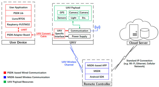
Figure 4.
Integrated Solution of “UAV + Remote Controller + Server”.
3. System Design
3.1. System Requirement Analysis
The UAV-assisted LoRaWAN networks are often deployed for applications such as smart agriculture, environmental monitoring, and emergency temporary networks. In such scenarios, where Wi-Fi and cellular coverage are inadequate, it is difficult to establish a stable connection between the LoRaWAN gateway and server. Thus, the UAV communication resources become a powerful solution in the UAV-assisted LoRaWAN network. In addition, to support real-time applications such as SaR (search and rescue), positioning, and forest fire monitoring, the GPS information is necessary for the ariel LoRaWAN gateway. Moreover, to leverage the existing LoRaWAN infrastructure and effectively expand current LoRaWAN applications, the system should follow the LoRaWAN protocol in both architecture and data forwarding.
Based on the above analysis, a UAV-assisted LoRaWAN architecture was proposed combining the integrated solution of “UAV + Remote Controller + Server” with the classical LoRaWAN network.
3.2. System Architecture
Like the ground LoRaWAN network and the existing UAV carrying a LoRaWAN gateway system, the star network topology architecture is adopted by the proposed system. The system consists of five components: (1) LoRaWAN end-devices, (2) UAV gateway, (3) remote controller, (4) cloud center server, and (5) application server, as shown in Figure 5. The figure also illustrates a scenario where the UAV system collaborates with the ground LoRaWAN network.
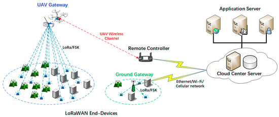
Figure 5.
UAV-assisted LoRaWAN network system architecture.
- LoRaWAN End-Devices
The LoRaWAN end-devices are responsible for collecting sensor data and generating RF LoRa or FSK packets. Thanks to the unified LoRaWAN standard, end-devices from different manufacturers can be compatible with each other, ensuring the interoperability of the LoRa devices.
- UAV Gateway
A UAV gateway consists primarily of a UAV and a LoRaWAN gateway, leveraging the altitude advantage of a UAV to enhance the longest communication distance of the gateway. However, the LoRaWAN gateway is not simply carried on the UAV. In fact, with the assistance of the PSDK, the LoRaWAN gateway can utilize the various resources of the UAV, including power supply, GSP ability, and the UAV communication link. Therefore, a more powerful and functional UAV-based LoRaWAN gateway was implemented. In particularly, the unstable network connection provided by Wi-Fi or cellular has been replaced by a UAV communication link, ensuring the reliability and robustness of the LoRaWAN network. Moreover, a program called UAV packet forwarder was developed on the gateway host, ensuring that the data forwarding adheres to the LoRaWAN protocol. In addition, the GSP capability was also obtained by the LoRaWAN gateway through the UAV packet forwarder, effectively supporting real-time LoRaWAN applications.
- Remote Controller
The remote controller serves as a relay node, realizing bidirectional and transparent forwarding between the UAV and the LoRaWAN server. This feature benefits from an MSDK-based APP on the remote controller. With a designed mechanism, the remote controller realizes a single relay between the UAV gateway and LoRaWAN server, effectively enlarging the network coverage. In addition, the remote controller behaves like a regular LoRaWAN gateway from the server’s perspective, effectively improving the scalability of the system. For example, replacing the ground gateway with a combination of a UAV gateway and remote controller can easily upgrade the ground LoRaWAN network.
- Cloud Center Server
The center server is responsible for network security, device, and traffic management. Typically, the center server is deployed on a cloud server, but deployment on local or virtual machines is also feasible. Any LoRaWAN network server such as TTN (The Things Network), ThingPark, and ChirpStack can serve as the center server. In this system, the open-source LoRaWAN network server, ChirpStack, is deployed on a Huawei cloud server as the center server. With the various service integrated in ChirpStack and the gRPC-based API, the system can be extended easily and flexibly.
- Application Server
The application server retrieves the data of interest from the center server and processes them for specific applications. A center server can provide data for multiple application servers at the same time, effectively supporting multiple LoRaWAN application scenarios. For example, in a livestock management scenario, positioning and data-collection application servers can be deployed at the same time. Therefore, the tracking and monitoring of animals can be implemented simultaneously. In addition, if a single application server is not enough to handle large amounts of data, the system capacity can be easily expanded through adding additional application servers.
3.3. System Workflow
With the altitude advantage of UAVs and the relay feature of remote controllers, the coverage and communication reliability of the UAV-assisted network have been significantly improved, effectively enhancing the LoRaWAN performance in complex environments.
Next, the workflow of the UAV-assisted network will be introduced through a typical smart agriculture scenario. First, the underground LoRaWAN end-devices collect various soil environmental parameters and periodically transmit them with LoRa or FSK modulation. Due to the mobility and LOS advantages of UAV, large-scale LoRaWAN end-devices can be covered with several UAV gateways. Once the RF LoRa packets are detected by the UAV gateway, they will be processed in the gateway host to generate a gateway uplink message. If the GPS of the gateway is available, the location of the gateway and reception timestamp of the LoRa packet will also be added into the gateway uplink message. Notably, the message will not be uploaded to the LoRaWAN server directly through the LoRaWAN gateway. With the integrated solution of “UAV + Remote Controller + Server”, the message will be relayed by the remote controller to ensure reliable communication with the LoRaWAN server. Subsequently, the packets from the LoRaWAN end-devices will be recorded in database by center server. Through the gRPC-based API, the application server can be developed to realize the monitoring and control of a crop-growing environment. If necessary, the positioning function can also be implemented through an integrated service such as LoRa Edge in ChirpStack or another positioning application server.
4. System Implementation
4.1. UAV Gateway Design
4.1.1. Hardware Design
The UAV gateway consists of three components: (1) a UAV, (2) a PSDK adapter board, and (3) a LoRaWAN gateway. They are tightly integrated together through wired connections, as shown in Figure 6.
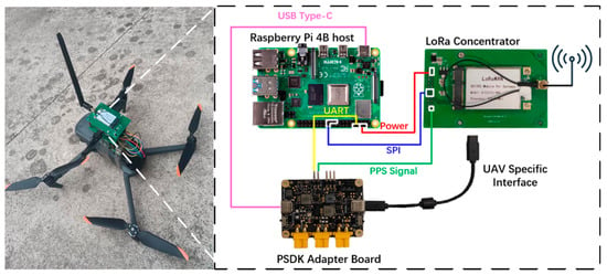
Figure 6.
UAV Gateway hardware design.
- UAV
The UAV model chosen by the system is DJI Mavic 3. The maximum payload weight of the UAV is 135 g, meeting the requirements for carrying the LoRaWAN gateway and PSDK adapter board. In unobstructed scenarios, the longest communication distance between the UAV and the remote controller can reach 8 km. Therefore, the longest communication distance of the proposed system is extended by 8 km, theoretically. In addition, PSDK and MSDK development tools are supported by this model. Therefore, various UAV resources such as power supply, communication, and payload capacity can be utilized by the LoRaWAN gateway, resulting in a robust and feature-rich LoRaWAN network.
- PSDK adapter board
The PSDK adapter board converts the specific interface on the UAV into various standard interfaces. Specifically, the PSDK adapter board provides a UART port for communication, a PPS signal port for clock synchronization, and a USB type-C port for both communication and power supply.
- LoRaWAN gateway
The LoRaWAN gateway is composed of a Raspberry Pi 4B host and a SX1302-based LoRa concentrator, which is driven through an SPI interface. Both UAV power and communication resources are leveraged to enhance gateway capability through the USB type-C and UART port. In addition, with the PPS signal, the gateway can synchronize with the UAV clock, enabling LoRaWAN Class B mode and LoRaWAN positioning based on the time difference of arrival (TDOA).
4.1.2. Software Design
A program called UAV packet forwarder was developed for data forwarding and coordinating UAV resources. On the one hand, the hardware platforms, LoRa concentrator and UAV communication module, were driven by the program to forward gateway messages. Inspired by the LoRa packet forwarder, the GWMP protocol is utilized for the communication between gateways and servers. On the other hand, with the GPS information and PPS signal of the UAV, GPS capabilities were obtained by the LoRaWAN gateway through this program. In detail, the above-mentioned functions are primarily achieved through three threads: thread up, thread down for data forwarding, and thread GPS for GPS management.
- Thread Up, Thread Down and GWMP-based data forwarding
The GWMP protocol defines the communication standard between the LoRaWAN gateway and the server, including the upstream and downstream protocols, as shown in Figure 7.
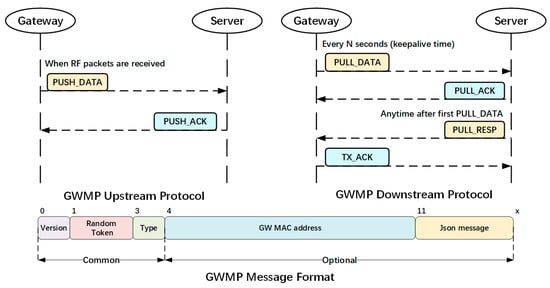
Figure 7.
GWMP Upstream protocol, Downstream protocol, and message format.
The upstream protocol defines the uplink data-processing mechanism. Once an RF LoRa packet is detected, the uplink message PUSH_DATA will be generated and sent to the server by the LoRaWAN gateway. Subsequently, a PUSH_ACK message will return from the server for confirmation.
The downstream protocol considers two scenarios: LoRaWAN gateway sending heartbeat packets and receiving downlink messages from a server. On the one hand, the LoRaWAN gateway should periodically send heartbeat packets, known as PULL_DATA, to the server. Receiving a PULL_ACK message from the server confirms network connectivity. On the other hand, when a downlink PULL_RESP message is received from the server, the gateway should forward it to the LoRaWAN end-devices. Additionally, a TX_ACK message should be sent to the server to report the forwarding result.
The messages defined in the GWMP protocol have a uniform format; each message contains at least four bytes. The first byte indicates the protocol version, followed by a 2-byte token, which is randomly generated for message validation. The fourth byte indicates the message type, from 0 to 5, corresponding to PUSH_DATA, PUSH_ACK, PULL_DATA, PUSH_RESP, PULL_ACK, or TX_ACK. In addition, the gateway MAC address should be carried for the uplink message, and JSON messages are used to carry additional information such as end-device data, gateway status, and server instructions.
According to the GWMP protocol, thread up and thread down are designed for upstream and downstream protocols, respectively.
Thread up is responsible for generating PUSH_DATA and processing PUSH_ACK, as shown in Figure 8. Once the LoRa or FSK packets are detected by the LoRa concentrator, a PUSH_DATA message will be organized according to the GWMP protocol. If necessary, the gateway status will also be added to the PUSH_DATA message. Notably, a PUSH_DATA message only composed of gateway status is also feasible. Subsequently, the PUSH_DATA message will be sent to the remote controller through the UAV wireless channel. Since there is only one receiving interface provided by the PSDK, the receiving operations are all performed by the thread down. Accordingly, a global variable named ACK_Flag is set to inform the thread up that the PULL_ACK message has been received by thread down. After sending PUSH_DATA, the thread will wait continuously for the corresponding PULL_ACK within 1 s. If the valid PUSH_ACK is received, the next round of PUSH_DATA sending will be initiated directly.
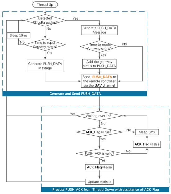
Figure 8.
Thread Up for GWMP Upstream protocol.
Thread down is responsible for sending PULL_DATA and receiving all the messages from the LoRaWAN server, as shown in Figure 9. The heartbeat packets called PULL_DATA will be periodically sent to verify the connectivity between the gateway and the LoRaWAN server. In addition, all the messages from the server are constantly monitored by the thread down, including PUSH_ACK, PULL_ACK, and PULL_RESP. When a PUSH_ACK message is received, the value of the ACK_Flag will be set to true to notify thread up; when a PULL_ACK message is received, the message validity will be confirmed to ensure that the server is available; when a PULL_RESP message is received, it will be added to the sending queue and sent immediately or scheduled according to server instructions. Subsequently, a corresponding TX_ACK message will be sent to the server for confirmation. Moreover, if the GPS is available, a beacon list will be checked periodically to enable the LoRaWAN Class-B mode application.
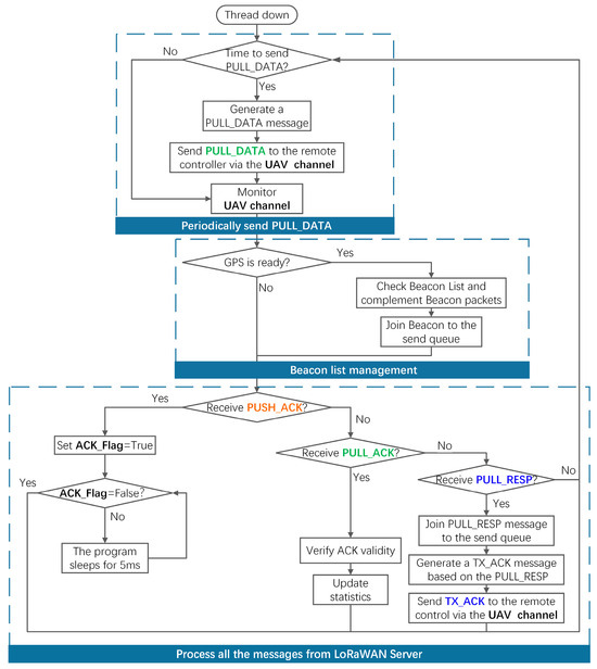
Figure 9.
Thread Down for GWMP Downstream protocol.
- Thread GPS and clock synchronization
Thread GPS is responsible for subscribing to the GPS location and synchronizing the gateway clock with the GPS. The GPS data of the UAV, in both NMEA and UBX protocols, are transmitted via UART at a frequency of 1 Hz. The NMEA data are parsed to provide GPS location, while UBX data are used for clock synchronization with the assistance of a PPS signal, as shown in Figure 10.
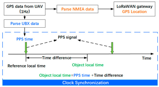
Figure 10.
Thread GPS for location subscription and clock synchronization.
The PPS signal will be triggered at the beginning of each second, with an accuracy of nanoseconds. When the PPS signal is triggered, an interrupt program will be initiated to record the reference local time. Subsequently, the GPS time from the UBX data will inform the exact trigger time of PPS signal. After that, any gateway local time can be converted to accurate GPS time through the reference local time and trigger time of the PPS signal.
4.2. Remote Controller Relay Design
LoRaWAN was originally designed with the single-hop star topology. However, the network coverage is restricted by the single-hop transmission in scenarios such as underground, indoor, and large-scale LoRaWAN applications. Therefore, the concepts of multi-hop and relay are proposed to improve network coverage, energy efficiency, and scalability [47,48,49,50]. This feature is also of concern by the LoRaWAN alliance, and the latest LoRaWAN protocol is constantly improving its support for relay features. Relay devices like Aria, designed by Deviceroy, have been implemented to enhance LoRaWAN performance.
In fact, the relay feature is also achieved through a remote controller. The remote controller serves as a relay node between the UAV gateway and the server, effectively expanding the coverage of network. On the one hand, the wireless communication between the remote controller and the UAV gateway has been established through the MSDK. On the other hand, with Wi-Fi or a cellular module, the remote controller is stably connected to the Internet. Therefore, transport transmission between the UAV gateway and the server can be realized through an MSDK-based APP on the remote controller. In addition, with the design of the data-forwarding mechanism, the compatibility of the LoRaWAN protocol is also guaranteed. The coverage of the LoRaWAN gateway has been expanded through the advantage of the UAV’s altitude. Thus, the single-hop relay of a remote controller is sufficient for most LoRaWAN scenarios.
An MSDK-based APP running on the remote controller was designed to implement the relay feature and LoRaWAN compatibility. Since the GWMP messages have been implemented in the UAV gateway, the remote controller should perform transparent data forwarding between the UAV gateway and server. Specifically, the APP should continuously monitor the date from both the UAV gateway and LoRaWAN server and, once data are received, forward them immediately.
To this end, the relay task was subdivided into downlink and uplink tasks, as shown in Figure 11. On the one hand, an independent thread was created for the downlink relay task, including a socket for monitoring and an MSDK-based forwarding operation. Once the forwarding operation is complete, the next round of monitoring will be initiated immediately. On the other hand, the uplink relay task was implemented in a similar way within the main loop. In addition, due to the half-duplex characteristics of UAV communication, the MSDK-based forwarding and monitoring operations cannot be carried out simultaneously. If no gateway uplink message is received for a long time, the UAV channel will always be occupied by monitoring operations, preventing the forwarding of downlink data. Therefore, the longest monitoring duration of a UAV channel is set to 50 ms, ensuring the timeliness of downlink data. In conclusion, with the downlink and uplink relay tasks, an invisible communication link is established between the UAV gateway and LoRaWAN server, effectively expanding the network coverage.
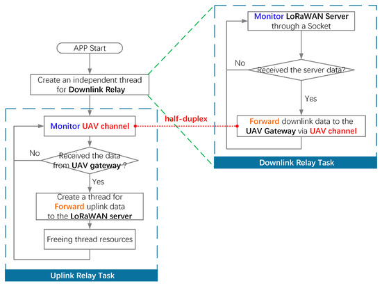
Figure 11.
Delay design for MSDK-based APP.
5. Performance Evaluation
Network coverage and communication reliability evaluation and positioning determination were carried out at the Northwestern Polytechnical University to prove the superiority of the system.
5.1. Network Coverage and Communication Reliability Evaluation
The purpose of this section is to evaluate the coverage and communication reliability of the system under different propagation environments. In addition, the influence of the LoRaWAN gateway position on the network performance was also analyzed.
5.1.1. Experimental Setting
A data-collection scenario was constructed through three LoRaWAN end-devices, a ground LoRaWAN gateway, the UAV gateway and remote controller, and a center server deployed on the cloud. The LoRaWAN end-devices are equipped with an ATmega328P-MU microcontroller and an SX1262-based LoRa transceiver, their transmission configurations are shown in Table 3. For the gateway software, the LoRa packet forwarder and UAV packet forwarder are utilized by the ground LoRaWAN gateway and UAV gateway, respectively, which both follow the GWMP protocol. For the gateway hardware, the SX1302-based LoRa concentrators are equipped on both the UAV gateway and ground gateway. The ground gateway connects to the center server directly through a Wi-Fi module, while the UAV gateway is through the integrated solution of “UAV + Remote Controller + Server”. The ChirpStack server is deployed on Huawei Cloud with an Ubuntu 22.04 image installed to serve as a center server.

Table 3.
Transmission configuration of LoRaWAN End-Devices.
To evaluate the performance of the system in different propagation environments, the three end-devices are deployed in different locations.
- Node_1 is deployed about 400 m southeast of the ground gateway, representing the urban propagation environment.
- Node_2 is deployed about 400 m southwest of the ground gateway, representing the vegetation propagation environment.
- Node_3 is deployed about 1.3 km southwest of the ground gateway, representing a complex propagation environment over long distances.
To compare the impact of different LoRaWAN gateway locations on the network performance, three groups of experiments involving five scenarios were designed.
- In group 1, the ground gateway is utilized to demonstrate the performance of the ground LoRaWAN network.
- In group 2, the ground gateway is replaced by the UAV gateway and remote controller to construct a UAV-assisted LoRaWAN network. In addition, three scenarios have been designed to analyze the effect of gateway altitude on network performance, where the UAV gateway is deployed at heights of 30 m, 60 m, and 90 m, respectively.
- In group 3, the UAV gateway is deployed at the center of three end-devices, which is 800 m away from the remote controller, aiming to verify the relay feature of the remote controller.
The network topology of three groups of experiments is shown in Figure 12a; the ground LoRaWAN gateway and LoRaWAN end-device utilized in the experiments are shown in Figure 12b,c.
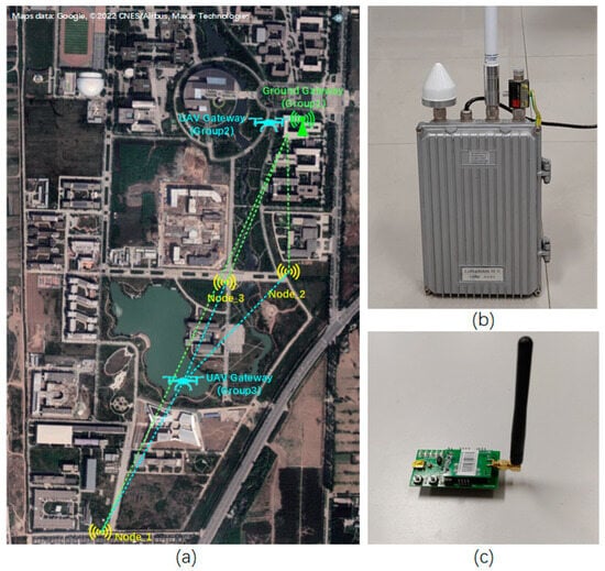
Figure 12.
(a) Network topology of three groups of experiments; (b) the ground LoRaWAN gateway; (c) the LoRaWAN End-Device.
5.1.2. Evaluation Indicators
The following indicators were selected to assess the system performance: (1) RSSI (received signal strength indicator), (2) SNR (signal-to-noise ratio), (3) PLR (packet loss rate), and (4) average transmission time.
Signal reception quality is measured by the RSSI and SNR. With the LoRa concentrator, the reception RSSI and SNR will be recorded by the gateway and reported to the LoRaWAN server.
The reliability of the communication is measured by the PLR, which represents the probability of packet loss during transmission. It is calculated by dividing the number of lost packets by the total number of sent packets. Each time a new packet is sent by the LoRaWAN end-device, the value of Fcnt in the packet is increased by 1. Thus, the total number of sent packets can be counted through the Fcnt change. In addition, the total number of packets received can be obtained through the gateway log, allowing for the calculation of packet loss ratio (PLR).
The average transmission time is defined as the average round trip time of a packet from the gateway to the server, measuring the transmission delay between the gateway and the server. For example, assuming a PULL_DATA message was sent by the LoRaWAN gateway to the LoRaWAN sever, the according PULL_ACK message was received. The interval between sending and receiving is called transmission time, and the average transmission time can be obtained by averaging all the transmission times. For the ground gateway, this time only includes the network delay between the gateway and the server; For the UAV gateway, the transmission time between the LoRaWAN gateway, UAV, and the remote controller is also considered. In the experiment, this time can also be obtained through the gateway log.
5.1.3. Experimental Results and Discussion
The data collection experiment was repeated five times during different periods of a week. For each scenario, the LoRaWAN gateway was continuously collecting data in a fixed position for 25 min. Since the end-devices were configured to send a LoRa packet every 10 s, theoretically, the LoRaWAN gateway received 2250 RF LoRa packets in each scenario. In addition, for the scenarios in group 2 where the UAV gateway is deployed at heights of 60 m and 90 m, two additional repetitions were performed to guarantee an accurate conclusion.
The reception SNR and RSSI of three LoRaWAN end-devices in each scenario are shown in Figure 13a,b. Focusing the performance of the ground gateway, it can be noted that the RSSI received by the ground gateway remain around −111 dbm across different propagation environments. However, the SNRs of Node_1, Node_2, and Node_3 were −10 db, −13 db, and −16 db, respectively, indicating a declining trend. It can be inferred that a complex environment with a long propagation distance results in the highest noise intensity, while a vegetation environment results in the lowest. Analyzing the three scenarios in group 2, where the gateway is deployed at heights of 30 m, 60 m, and 90 m, for Node_2 and Node_3, the height of the LoRaWAN gateway is positively correlated with the SNR and RSSI value. The improvement is especially noticeable when the LoRaWAN gateway is raised from 30 m to 60 m. However, for Node_1, the RSSI and SNR experience an unexpected decrease when the height of the gateway changes from 60 m to 90 m. It is speculated that this phenomenon is due to the shape characteristics of the shrubs in front of Node_1.
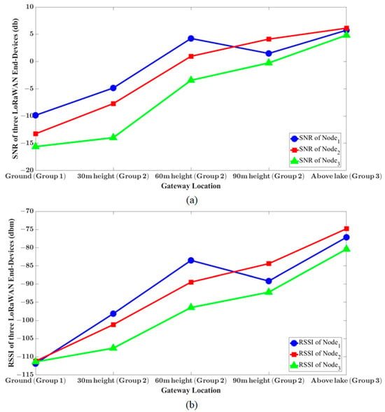
Figure 13.
(a) Reception SNR of three LoRaWAN End-Devices in each scenario; (b) reception RSSI of three LoRaWAN End-Devices in each scenario.
The lower part of the shrub has sparse foliage, whereas higher up it is dense and lush. Thus, as the gateway height increases, more obstacles are introduced to the propagation environment, leading to performance decreases, as shown in Figure 14. Finally, when the UAV is deployed above the lake, all the end-devices achieve excellent reception performance, with an RSSI of −80 dbm and an SNR of 4.5 db. In conclusion, compared with the ground gateway, the RSSI and SNR of the UAV gateway are significantly improved, especially when the UAV is deployed at high altitudes. It indicates that the coverage of the LoRaWAN network is significantly improved by the UAV. Moreover, the last scenario in group 3 verified the relay capability of the remote controller, which successfully enlarges the network’s communication distance by 800 m.
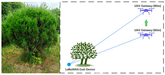
Figure 14.
The shrubs in front of Node_1 and analysis of anomaly.
The PLRs of the three LoRaWAN end-devices in each scenario are shown in Figure 15. For the ground gateway scenario, the PLR of each end-device reaches a value higher than 10%. Especially for Node_3, which represents complex propagation environment, it suffers a high PLR as 72.18%. In fact, Node_3 is unreachable in several experiments; the PLR in Figure 15 is obtained when Node_3 is available. For scenarios where the UAV is deployed at 90 m and above the lake, the PLR of all end-devices drops below 3%. In contrast, the PLR is significantly reduced by the UAV, effectively improving the communication reliability of the LoRaWAN network.
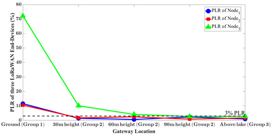
Figure 15.
The PLR of three LoRaWAN End-Devices in each scenario.
The average transmission time in each scenario is shown in Figure 16. The shortest average transmission time of 51 ms is achieved by the ground gateway. For the UAV gateway, this time is about 170 ms and increases with the distance between the UAV and remote controller. in the scenario in group3, where the UAV gateway is deployed above the lake, the distance between the UAV and remote controller reaches a maximum value of 800 m. Correspondingly, the average transmission time reaches a maximum value of 187.18 ms. Due to the maximum packet waiting time of thread up being 1000 ms, the increased delay has negligible impact on the transmission reliability.
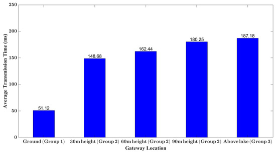
Figure 16.
The average transmission time in each scenario.
5.2. Positioning Demonstration
This section shows the application scalability of the system through a TDOA-based positioning demonstration.
5.2.1. TDOA Positioning Configuration
A TDOA-based LoRaWAN positioning scenario was constructed through a LoRaWAN end-device, two ground LoRaWAN gateways, the UAV gateway and remote controller, a ChirpStack deployed on the cloud, and a TDOA positioning application server. Since the TDOA algorithm requires strict gateway synchronization, the u-blox-7N GPS module was equipped for ground LoRaWAN gateways. For the UAV gateway, the GPS ability has been obtained through a UAV packet forwarder. Moreover, the GPS module was also equipped for the LoRaWAN end-device, providing the actual end-device GPS location for the position accuracy calculation. The remaining configurations of the LoRaWAN gateway, end-device, and center server are equal to the previous experiment. In addition, a TDOA positioning application server was developed through the gRPC-based API of ChirpStack.
Two topologies were designed to show the positioning performance of the UAV-assisted LoRaWAN network. In the first topology, the three LoRaWAN gateways are densely deployed. The distances between the three LoRaWAN gateways and the end-device are almost the same, which are 522 m, 458 m, and 303 m, respectively, as shown in Figure 17a. In the other topology, the locations of the UAV gateway and the LoRaWAN end-device were changed to form a dispersed gateway deployment, as shown in Figure 17b. In this scenario, the distance between the UAV gateway and the LoRaWAN end-device is approximately 927 m, while the distances between the ground LoRaWAN gateways and the LoRaWAN end-device are 584 m and 661 m, respectively.
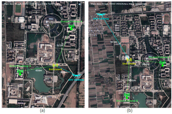
Figure 17.
(a) Positioning experiment with dense gateway topology; (b) positioning experiment with dispersed gateway topology.
5.2.2. TDOA Algorithm Implementation
After the deployment is complete, all the necessary data for positioning such as the timestamps of a packet arriving through different gateways, the location of gateways, and the actual GPS location of the end-device will be recorded by the ChirpStack server. Thus, with the gRPC-based API and ChirpStack SDKs, a TDOA application server was implemented. The pseudocode of TDOA is shown in Algorithm 1.
| Algorithm 1 Positioning Method Based on TDOA (Time Difference of Arrival) |
| Input: timestamps of a packet arriving at 3 different gateways, the GPS coordinates of gateways; |
| Output: Calculated End-Device location; |
| (1) Acquire information from Center Server. (2) Randomly choose a gateway as reference gateway. (3) Set the coordinates of reference gateway to (0, 0) at a two-dimensional plane. (4) Project the GPS coordinates of other gateways onto the two-dimensional plane. (5) Calculate the distance difference of gateways to End-Device based on timestamps difference, with the aim of formulating hyperbolic equations. (6) if the calculated distance difference of gateways to End-Device is outlier return to step 1 else return calculated End-Device location based on hyperbolic equations. |
First, the GPS coordinates of the three gateways should be projected onto a two-dimensional plane. Specifically, one of the gateways is chosen as the reference gateway, and its coordinates are set to (0, 0). Subsequently, the coordinates of the remaining two gateways will be calculated through Equation (1):
where X and Y are the converted horizontal and vertical coordinates, respectively. R is the mean radius of the Earth, measured in m. lon and lonref are the GSP longitude of the target gateway and the reference gateway, respectively, and lat and latref are the GSP latitude of the target gateway and the reference gateway, respectively.
Subsequently, the time difference information of the packet to the gateways and the distance difference from the end-device to the gateways can be obtained. Therefore, hyperbolic curves can be drawn at the two-dimensional plane to estimate end-device location. The GPS position of the LoRaWAN end-device can be obtained through inverse calculation of Equation (1). Notably, since only three LoRaWAN gateways were deployed for positioning, the clock skew of the LoRaWAN gateway and multipath effects significantly influence the positioning results. Therefore, a simple filtering mechanism was proposed to eliminate outliers: If the calculated distance difference of two LoRaWAN gateways through timestamps is larger than the real-world distance, these data will be discarded.
5.2.3. Positioning Result and Discuss
In both dense gateway topology and dispersed gateway topology, the positioning experiments were conducted four times, each lasting 30 min.
In dense gateway topology, four group positioning results were obtained by the TDOA positioning server. The original positioning accuracy is 236 m, 244 m, 212 m, and 247 m, respectively, and the accuracy reached 215 m, 215 m, 220 m, and 206 m after being processed by the filtering mechanism, as shown in Figure 18. With only three LoRaWAN gateways, the system achieved an average positioning accuracy of 213 m through a simple filtering mechanism. It proved that the UAV-assisted LoRaWAN network can effectively support real-time LoRaWAN applications.
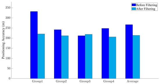
Figure 18.
Positioning accuracy with dense gateway topology.
Similarly, four group positioning results were obtained by the TDOA positioning server when the LoRaWAN gateways are dispersedly deployed. However, the original positioning accuracy exhibits significant errors: 11,625 m, 2077 m, 7053 m, and 8921 m, respectively. Upon verification, it is found that approximately 10% of the data have significant positioning errors, with frequent typical values including 3896 m, 104,979 m, 35,031 m, and 62,516 m. After applying the filtering mechanism, these anomalous data were successfully removed and reached an average positioning accuracy of 195 m, as shown in Figure 19.
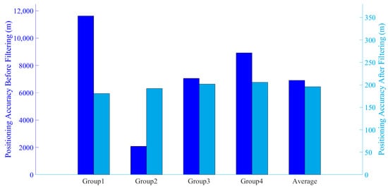
Figure 19.
Positioning accuracy with dispersed gateway topology.
To identify the cause of the significant positioning errors, the original timestamp data were carefully analyzed, revealing an abnormal phenomenon. As mentioned earlier, the distance between the LoRaWAN end-device and the UAV gateway is about 300 m farther than the end-device to ground gateway. Since the spread speed of a LoRa signal is 3 × 10⁸ m/s, approximately, the RF LoRa packet should arrive at the UAV gateway about 1 us after reaching the ground gateway. However, in the anomalous data, RF LoRa packets arrive at the UAV gateway before reaching the ground gateway, and in a few cases, they arrive up to 3 us earlier. The phenomenon indicated that ground gateways are significantly affected by multipath propagation caused by the buildings, while the UAV effectively avoided it, demonstrating the robustness of the UAV system.
6. Conclusions
In this paper, a UAV-assisted LoRaWAN network is proposed to improve the coverage and communication reliability of the LoRaWAN network in a complex environment. A highly scalable and portable architecture based on the integrated solution of “UAV + Remote Controller + Server” was proposed to integrate a UAV with a LoRaWAN network. Moreover, a PSDK-based LoRaWAN gateway was implemented to leverage various UAV resources, especially the UAV communication resources for reliable connection between gateway and LoRaWAN server. In addition, an MSDK-based APP was designed to further expand the coverage of LoRaWAN through a single-hop relay.
The improvement of the UAV-assisted LoRaWAN network in network coverage, communication reliability, and application scalability were demonstrated in both data collection and positioning scenarios. Specifically, when the end-device is deployed 1.3 km away with numerous obstacles in the propagation environment, with the altitude advantage of the UAV, the proposed system achieved an SNR of −2 db and an RSSI of −93 dbm with a packet loss rate of 3%. After leveraging the relay capability of the remote controller, the SNR further improved to 5 db and the RSSI rose to −80 dbm. In comparison, the ground gateway only achieved an SNR of −16 db and an RSSI of −113 dbm with a packet loss rate of 73%.
In addition, with only a UAV gateway and two ground gateways, the system reached a TDOA positioning accuracy of about 200 m through a simple filtering mechanism. Moreover, the robustness of the UAV to multipath effects is also demonstrated.
Recently, some research also combined LoRaWAN gateways with low-Earth-orbit (LEO) satellites as the supplement of the ground LoRaWAN network [51,52]. LEO satellites offer global connectivity, effectively overcoming the difficulties of deploying ground LoRaWAN gateways in deserts, oceans, and other remote areas. However, LEO satellite systems also encounter significant challenges, including serious Doppler effects, expensive system costs, and data packet collisions due to increased end-device access. Zadorozhny et al. tested the LoRa modulation performance using a NORBY CubeSat operating at 560 km [53]. With a transmission power of 4 W and a receive antenna gain of 14.5 dbi, the RSSI of the LoRa signal ranges from −90 to −120 dbm, while the SNR ranges from −5 to 10 db. Moreover, when SF11 and SF12 was applied, the Doppler effect catastrophically affected the LoRa transmission. In contrast, the UAV-assisted LoRaWAN system can achieve the same performance with lower transmission power and system costs, while being less affected by the Doppler effect.
Compared with the fixed ground LoRaWAN gateway, the UAV gateway cannot remain airborne indefinitely, which can be a limitation to the UAV-assisted LoRaWAN network. In the implemented system, the UAV called Mavic 3E was equipped with a 77 Wh removable battery, allowing for a single flight duration of up to 45 min. However, due to the additional burden the gateway placed on the UAV and the minor power consumption of the LoRa gateway, the actual effective data collection duration is approximately 35 min, assuming the UAV reserves sufficient battery power for returning (about 15%). Considering the max flying speed of 15 m/s and the enlarged network coverage, this time is enough for most LoRaWAN applications. However, more than three backup batteries are required for long-duration data collection tasks. Therefore, in the next stage, the open-source UAV platforms are considered to customize the high-endurance, low-cost LoRaWAN gateway flight platform.
Author Contributions
Conceptualization, H.Z., W.T., Y.L. and W.C.; methodology, H.Z. and W.T.; software, H.Z. and W.T.; validation, S.C. and A.L.; formal analysis, S.C. and A.L.; investigation, H.Z. and W.T.; resources, H.Z., Y.L. and W.C.; data curation, W.T., S.C. and A.L.; writing—original draft preparation, H.Z. and W.T.; writing—review and editing, H.Z., W.T., Y.L. and W.C.; visualization, S.C. and A.L.; supervision, Y.L. and W.C.; project administration, H.Z., Y.L. and W.C.; funding acquisition, H.Z., Y.L. and W.C. All authors have read and agreed to the published version of the manuscript.
Funding
This work is supported by the Fundamental Research Funds for the Central Universities (No. D5000230154) and the Key Research and Development Program of Shaanxi under Grant 2024GX-YBXM-022.
Data Availability Statement
Data will be made available on reasonable request.
Conflicts of Interest
The authors declare no conflicts of interest.
References
- Semtech LoRa Technology Overview. Available online: https://www.semtech.com/lora (accessed on 2 August 2024).
- Manzano, L.G.; Boukabache, H.; Danzeca, S.; Heracleous, N.; Murtas, F.; Perrin, D.; Pirc, V.; Alfaro, A.R.; Zimmaro, A.; Silari, M. An IoT LoRaWAN Network for Environmental Radiation Monitoring. IEEE Trans. Instrum. Meas. 2021, 70, 1–12. [Google Scholar] [CrossRef]
- Das, V.V.; Sathyan, A.; Divya, D.S. Establishing LoRa Based Local Agri-Sensor Network through Sensor Plugin Modules and LoRaWAN Data Concentrator for Extensive Agriculture Automation. In Proceedings of the 2022 IEEE 19th India Council International Conference (INDICON), Kochi, India, 24–26 November 2022; pp. 1–6. [Google Scholar]
- Kostadinov, A.; Kolev, K. LoRa Smart City Applications. In Proceedings of the 2022 29th International Conference on Systems, Signals and Image Processing (IWSSIP), Sofia, Bulgaria, 1–3 June 2022; pp. 1–4. [Google Scholar]
- Cruz, N.; Cota, N.; Tremoceiro, J. LoRaWAN and Urban Waste Management—A Trial. Sensors 2021, 21, 2142. [Google Scholar] [CrossRef] [PubMed]
- Abubeker, K.M.; Baskar, S. A Hand Hygiene Tracking System with LoRaWAN Network for the Abolition of Hospital-Acquired Infections. IEEE Sens. J. 2023, 23, 7608–7615. [Google Scholar] [CrossRef]
- Adi, P.D.P.; Wahyu, Y. The Error Rate Analyze and Parameter Measurement on LoRa Communication for Health Monitoring. Microprocess. Microsyst. 2023, 98, 104820. [Google Scholar] [CrossRef]
- Mahjoub, T.; Ben Said, M.; Boujemaa, H. Experimental Analysis of LoRa Signal in Urban Environment. In Proceedings of the 2022 International Wireless Communications and Mobile Computing (IWCMC), Dubrovnik, Croatia, 30 May–3 June 2022; pp. 812–817. [Google Scholar]
- Wu, Z.; Shen, Q.; Wang, J. Researching on Signal Transmission Performance of LoRa Technology in Urban Environment. In Proceedings of the 2023 IEEE 12th Data Driven Control and Learning Systems Conference (DDCLS), Xiangtan, China, 12–14 May 2023; pp. 1056–1061. [Google Scholar]
- Gonzalez, C.; Gibeaux, S.; Ponte, D.; Espinosa, A.; Pitti, J.; Nolot, F. An Exploration of LoRa Network in Tropical Farming Environment. In Proceedings of the 2022 IEEE 2nd International Conference on Computer Communication and Artificial Intelligence (CCAI), Beijing, China, 6–8 May 2022; pp. 182–186. [Google Scholar]
- Sharma, A.; Singh Kapoor, D.; Nayyar, A.; Qureshi, B.; Jot Singh, K.; Thakur, K. Exploration of IoT Nodes Communication Using LoRaWAN in Forest Environment. Comput. Mater. Contin. 2022, 71, 6239–6256. [Google Scholar] [CrossRef]
- Ferreira, A.E.; Ortiz, F.M.; Costa, L.H.M.K.; Foubert, B.; Amadou, I.; Mitton, N. A Study of the LoRa Signal Propagation in Forest, Urban, and Suburban Environments. Ann. Telecommun. 2020, 75, 333–351. [Google Scholar] [CrossRef]
- Villarim, M.R.; Vitor Holanda De Luna, J.; De Farias Medeiros, D.; Imaculada Soares Pereira, R.; De Souza, C.P.; Baiocchi, O.; Da Cunha Martins, F.C. An Evaluation of LoRa Communication Range in Urban and Forest Areas: A Case Study in Brazil and Portugal. In Proceedings of the 2019 IEEE 10th Annual Information Technology, Electronics and Mobile Communication Conference (IEMCON), Vancouver, BC, Canada, 17–19 October 2019; pp. 0827–0832. [Google Scholar]
- Pakrooh, R.; Bohlooli, A. A Survey on Unmanned Aerial Vehicles-Assisted Internet of Things: A Service-Oriented Classification. Wirel. Pers. Commun. 2021, 119, 1541–1575. [Google Scholar] [CrossRef]
- Gu, X.; Zhang, G. A Survey on UAV-Assisted Wireless Communications: Recent Advances and Future Trends. Comput. Commun. 2023, 208, 44–78. [Google Scholar] [CrossRef]
- Wei, Z.; Zhu, M.; Zhang, N.; Wang, L.; Zou, Y.; Meng, Z.; Wu, H.; Feng, Z. UAV-Assisted Data Collection for Internet of Things: A Survey. IEEE Internet Things J. 2022, 9, 15460–15483. [Google Scholar] [CrossRef]
- Torres-Sanz, V.; Sanguesa, J.A.; Serna, F.; Martinez, F.J.; Garrido, P.; Calafate, C.T. Analysis of the Influence of Terrain on LoRaWAN-Based IoT Deployments. In Proceedings of the Int’l ACM Conference on Modeling Analysis and Simulation of Wireless and Mobile Systems, Montreal, QC, Canada, 30 October 2023; pp. 217–224. [Google Scholar]
- Dambal, V.A.; Mohadikar, S.; Kumbhar, A.; Guvenc, I. Improving LoRa Signal Coverage in Urban and Sub-Urban Environments with UAVs. In Proceedings of the 2019 International Workshop on Antenna Technology (iWAT), Miami, FL, USA, 3–6 March 2019; pp. 210–213. [Google Scholar]
- Bariah, L.; Jaafar, W.; Muhaidat, S.; Elgala, H.; Yanikomeroglu, H. On the Error Performance of LoRa-Enabled Aerial Networks Over Shadowed Rician Fading Channels. IEEE Commun. Lett. 2022, 26, 2322–2326. [Google Scholar] [CrossRef]
- Xiong, R.; Liang, C.; Zhang, H.; Xu, X.; Luo, J. FlyingLoRa: Towards Energy Efficient Data Collection in UAV-Assisted LoRa Networks. Comput. Netw. 2023, 220, 109511. [Google Scholar] [CrossRef]
- Panga, S.M.S.; Borkotoky, S.S. Leveraging Wake-Up Radios in UAV-Aided LoRa Networks: Some Preliminary Results on a Random-Access Scheme. In Proceedings of the 2023 17th International Conference on Telecommunications (ConTEL), Graz, Austria, 11–13 July 2023; pp. 1–7. [Google Scholar]
- Bianco, G.M.; Marrocco, G. Body-UAV Near-Ground LoRa Links through a Mediterranean Forest. IEEE Trans. Antennas Propagat. 2023, 71, 6214–6218. [Google Scholar] [CrossRef]
- Andreadis, A.; Giambene, G.; Zambon, R. Role of UAVs and HAPS for IoT-Based Monitoring in Emergency Scenarios. In Proceedings of the 2023 International Conference on Information and Communication Technologies for Disaster Management (ICT-DM), Cosenza, Italy, 13–15 September 2023; pp. 1–8. [Google Scholar]
- Jia, B.; Qiao, W.; Huang, B.; Yang, H.; Wang, E. Sequentially Localizing LoRa Terminals with A Single UAV. In Proceedings of the 2023 IEEE Wireless Communications and Networking Conference (WCNC), Glasgow, UK, 26–29 March 2023; pp. 1–6. [Google Scholar]
- Andreadis, A.; Giambene, G.; Zambon, R. Low-Power IoT for Monitoring Unconnected Remote Areas. Sensors 2023, 23, 4481. [Google Scholar] [CrossRef] [PubMed]
- Zhang, Z.; Zhou, C.; Sheng, L.; Cao, S. Optimization Schemes for UAV Data Collection with LoRa 2.4 GHz Technology in Remote Areas without Infrastructure. Drones 2022, 6, 173. [Google Scholar] [CrossRef]
- Trasviña-Moreno, C.; Blasco, R.; Marco, Á.; Casas, R.; Trasviña-Castro, A. Unmanned Aerial Vehicle Based Wireless Sensor Network for Marine-Coastal Environment Monitoring. Sensors 2017, 17, 460. [Google Scholar] [CrossRef] [PubMed]
- Vlasceanu, E.; Dima, M.; Popescu, D.; Ichim, L. Sensor and Communication Considerations in UAV-WSN Based System for Precision Agriculture. In Proceedings of the 2019 IEEE International Conference on Cybernetics and Intelligent Systems (CIS) and IEEE Conference on Robotics, Automation and Mechatronics (RAM), Bangkok, Thailand, 18–20 November 2019; pp. 281–286. [Google Scholar]
- Holtorf, L.; Titov, I.; Daschner, F.; Gerken, M. UAV-Based Wireless Data Collection from Underground Sensor Nodes for Precision Agriculture. AgriEngineering 2023, 5, 338–354. [Google Scholar] [CrossRef]
- Cariou, C.; Moiroux-Arvis, L.; Pinet, F.; Chanet, J.-P. Data Collection from Buried Sensor Nodes by Means of an Unmanned Aerial Vehicle. Sensors 2022, 22, 5926. [Google Scholar] [CrossRef]
- Zhang, M.; Li, X. Drone-Enabled Internet-of-Things Relay for Environmental Monitoring in Remote Areas without Public Networks. IEEE Internet Things J. 2020, 7, 7648–7662. [Google Scholar] [CrossRef]
- Chen, L.-Y.; Huang, H.-S.; Wu, C.-J.; Tsai, Y.-T.; Chang, Y.-S. A LoRa-Based Air Quality Monitor on Unmanned Aerial Vehicle for Smart City. In Proceedings of the 2018 International Conference on System Science and Engineering (ICSSE), New Taipei, Taiwan, 28–30 June 2018; pp. 1–5. [Google Scholar]
- Camarillo-Escobedo, R.; Flores, J.L.; Marin-Montoya, P.; García-Torales, G.; Camarillo-Escobedo, J.M. Smart Multi-Sensor System for Remote Air Quality Monitoring Using Unmanned Aerial Vehicle and LoRaWAN. Sensors 2022, 22, 1706. [Google Scholar] [CrossRef]
- Martinez-Caro, J.-M.; Cano, M.-D. IoT System Integrating Unmanned Aerial Vehicles and LoRa Technology: A Performance Evaluation Study. Wirel. Commun. Mob. Comput. 2019, 2019, 4307925. [Google Scholar] [CrossRef]
- Chen, C.; Luo, J.; Xu, Z.; Xiong, R.; Yin, Z.; Lin, J.; Shen, D. LoRaDrone: Enabling Low-Power LoRa Data Transmission via a Mobile Approach. In Proceedings of the 2022 18th International Conference on Mobility, Sensing and Networking (MSN), Guangzhou, China, 14–16 December 2022; pp. 239–246. [Google Scholar]
- Chen, C.; Luo, J.; Xu, Z.; Xiong, R.; Shen, D.; Yin, Z. Enabling Large-Scale Low-Power LoRa Data Transmission via Multiple Mobile LoRa Gateways. Comput. Netw. 2023, 237, 110083. [Google Scholar] [CrossRef]
- De Rango, F.; Stumpo, D. Supporting Path Planning in LoRa-Based UAVs for Dynamic Coverage for IoT Devices. In Proceedings of the 2023 IEEE 20th Consumer Communications & Networking Conference (CCNC), Las Vegas, NV, USA, 8–11 January 2023; pp. 337–340. [Google Scholar]
- Ferreira, F.H.C.D.S.; Neto, M.C.D.A.; Barros, F.J.B.; Araújo, J.P.L.D. Intelligent Drone Positioning via BIC Optimization for Maximizing LPWAN Coverage and Capacity in Suburban Amazon Environments. Sensors 2023, 23, 6231. [Google Scholar] [CrossRef]
- Vishnevskiy, V.M.; Samouylov, K.E.; Kozyrev, D.V. (Eds.) Distributed Computer and Communication Networks. In Proceedings of the 19th International Conference, DCCN 2016, Moscow, Russia, 21–25 November 2016; Revised Selected Papers; Communications in Computer and Information Science. Springer International Publishing: Cham, Switzerland, 2016; Volume 678, ISBN 978-3-319-51916-6. [Google Scholar]
- Moheddine, A.; Patrone, F.; Marchese, M. UAV and IoT Integration: A Flying Gateway. In Proceedings of the 2019 26th IEEE International Conference on Electronics, Circuits and Systems (ICECS), Genoa, Italy, 27–29 November 2019; pp. 121–122. [Google Scholar]
- Almalki, F.A.; Soufiene, B.O.; Alsamhi, S.H.; Sakli, H. A Low-Cost Platform for Environmental Smart Farming Monitoring System Based on IoT and UAVs. Sustainability 2021, 13, 5908. [Google Scholar] [CrossRef]
- Park, S.; Yun, S.; Kim, H.; Kwon, R.; Ganser, J.; Anthony, S. Forestry Monitoring System Using LoRa and Drone. In Proceedings of the 8th International Conference on Web Intelligence, Mining and Semantics, Novi Sad, Serbia, 25–27 June 2018; pp. 1–8. [Google Scholar]
- Delafontaine, V.; Schiano, F.; Cocco, G.; Rusu, A.; Floreano, D. Drone-Aided Localization in LoRa IoT Networks. In Proceedings of the 2020 IEEE International Conference on Robotics and Automation (ICRA), Paris, France, 31 May–31 August 2020; pp. 286–292. [Google Scholar]
- Behjati, M.; Mohd Noh, A.B.; Alobaidy, H.A.H.; Zulkifley, M.A.; Nordin, R.; Abdullah, N.F. LoRa Communications as an Enabler for Internet of Drones towards Large-Scale Livestock Monitoring in Rural Farms. Sensors 2021, 21, 5044. [Google Scholar] [CrossRef]
- Mohd Noh, A.; Nordin, R. Empirical Study of Drone-LoRa Enable Performance to Doppler Robustness for Livestock Industry. Int. J. Integr. Eng. 2022, 14, 212–227. [Google Scholar] [CrossRef]
- Gallego-Madrid, J.; Molina-Zarca, A.; Sanchez-Iborra, R.; Bernal-Bernabe, J.; Santa, J.; Ruiz, P.M.; Skarmeta-Gómez, A.F. Enhancing Extensive and Remote LoRa Deployments through MEC-Powered Drone Gateways. Sensors 2020, 20, 4109. [Google Scholar] [CrossRef]
- Leenders, G.; Ottoy, G.; Callebaut, G.; Van Der Perre, L.; De Strycker, L. An Energy-Efficient LoRa Multi-Hop Protocol through Preamble Sampling. In Proceedings of the 2023 IEEE Wireless Communications and Networking Conference (WCNC), Glasgow, UK, 26–29 March 2023; pp. 1–6. [Google Scholar]
- Cotrim, J.R.; Margi, C.B.; Kleinschmidt, J.H. Design of a Gateway-Based Relay Node for LoRaWAN Multihop Networks. In Proceedings of the 2022 Symposium on Internet of Things (SIoT), São Paulo, Brazil, 24–28 October 2022; pp. 1–4. [Google Scholar]
- Prade, L.; Moraes, J.; De Albuquerque, E.; Rosário, D.; Both, C.B. Multi-Radio and Multi-Hop LoRa Communication Architecture for Large Scale IoT Deployment. Comput. Electr. Eng. 2022, 102, 108242. [Google Scholar] [CrossRef]
- Wong, A.W.-L.; Goh, S.L.; Hasan, M.K.; Fattah, S. Multi-Hop and Mesh for LoRa Networks: Recent Advancements, Issues, and Recommended Applications. ACM Comput. Surv. 2024, 56, 1–43. [Google Scholar] [CrossRef]
- Tondo, F.A.; Afhamisis, M.; Montejo-Sánchez, S.; López, O.L.A.; Palattella, M.R.; Souza, R.D. Multiple Channel LoRa-to-LEO Scheduling for Direct-to-Satellite IoT. IEEE Access 2024, 12, 30627–30637. [Google Scholar] [CrossRef]
- Zhou, W.; Hong, T.; Ding, X.; Zhang, G. LoRa Performance Analysis for LEO Satellite IoT Networks. In Proceedings of the 2021 13th International Conference on Wireless Communications and Signal Processing (WCSP), Changsha, China, 20–22 October 2021; pp. 1–5. [Google Scholar]
- Zadorozhny, A.M.; Doroshkin, A.A.; Gorev, V.N.; Melkov, A.V.; Mitrokhin, A.A.; Prokopyev, V.Y.; Prokopyev, Y.M. First Flight-Testing of LoRa Modulation in Satellite Radio Communications in Low-Earth Orbit. IEEE Access 2022, 10, 100006–100023. [Google Scholar] [CrossRef]
Disclaimer/Publisher’s Note: The statements, opinions and data contained in all publications are solely those of the individual author(s) and contributor(s) and not of MDPI and/or the editor(s). MDPI and/or the editor(s) disclaim responsibility for any injury to people or property resulting from any ideas, methods, instructions or products referred to in the content. |
© 2024 by the authors. Licensee MDPI, Basel, Switzerland. This article is an open access article distributed under the terms and conditions of the Creative Commons Attribution (CC BY) license (https://creativecommons.org/licenses/by/4.0/).