Article

Delivery Route Scheduling of Heterogeneous Robotic System with Customers Satisfaction by Using Multi-Objective Artificial Bee Colony Algorithm

1
Engineering Research Center for Metallurgical Automation and Measurement Technology of Ministry of Education, Wuhan University of Science and Technology, Wuhan 430081, China
2
Institute of Robotics and Intelligent Systems, Wuhan University of Science and Technology, Wuhan 430081, China
3
School of Architecture and Urban Planning, Guangzhou University, Guangzhou 510006, China
*
Authors to whom correspondence should be addressed.
Drones 2024, 8(10), 519; https://doi.org/10.3390/drones8100519
Submission received: 28 August 2024 / Revised: 18 September 2024 / Accepted: 20 September 2024 / Published: 24 September 2024

Abstract

:
This study addresses the route scheduling problem for the heterogeneous robotic delivery system (HRDS) that perform delivery tasks in an urban environment. The HRDS comprises two distinct types of vehicles: an unmanned ground vehicle (UGV), which is constrained by road networks, and an unmanned aerial vehicle (UAV), which is capable of traversing terrain but has limitations in terms of energy and payload. The problem is formulated as an optimal route scheduling problem in a road network, where the goal is to find the route with minimum delivery cost and maximum customer satisfaction (CS) enabling the UAV to deliver packages to customers. We propose a new method of route scheduling based on an improved artificial bee colony algorithm (ABC) and the non-dominated sorting genetic algorithm II (NSGA-II) that provides the optimal delivery route. The effectiveness and superiority of the method we proposed are demonstrated by comparison in simulations. Moreover, the physical experiments further validate the practicality of the model and method.

1. Introduction

The rapid development of e-commerce has brought many opportunities and challenges to the express delivery industry. With the improvement of delivery efficiency and service quality, market competition has become increasingly intense. In this context, the application of mobile robots in the express delivery field is attracting considerable critical attention [1]. Especially unmanned ground vehicles (UGV) and unmanned aerial vehicles (UAV) have been widely used for parcel delivery [2]. UAVs benefit from their aerial mode of transportation, enabling them to overcome barriers of time and space [3]. UGVs excel at large-scale delivery tasks due to their excellent endurance and carrying capacity [4]. However, UAVs are usually limited in application scenarios because of energy and load constraints, while UGVs are generally limited in movement due to the restrictions of ground obstacles [5]. To address the limitations of individual robots, many fields [6,7] have begun exploring UAV-aided UGV solutions to achieve better results. Therefore, a novel system composed of UGVs and UAVs has been conceptualized, called the Heterogeneous Robotic Delivery System (HRDS) [8]. This system not only has the merit of a wide range for delivery but also has the characteristics of flexible distribution.
One of the most critical tasks in HRDS is to schedule routes, i.e., assigning the best route for UAVs and UGVs. Many researchers have devoted their efforts to this field. Murray and Chu [9] proposed HRDS and developed models such as the Flying Sidekick Traveling Salesman Problem (FSTSP) and Parallel Drone Scheduling Traveling Salesman Problem (PDSTSP). Agatz et al. [10] studied the hybrid delivery model of ’last-mile’ delivery using HRDS and demonstrated that HRDS reduces costs compared to the UGV-only model. Kitjacharoenchai [11] proposed a new routing model that considers a synchronized HRDS operation by allowing multiple UAVs to fly from a UGV, serve one or multiple customers, and return to the same UGV for a battery swap and package retrieval. Wang et al. [12] addressed UAV/UGV scheduling by solving fixed and discrete charging set problems and introducing additional tasks for UGVs beyond recharging UAVs, using graph-based methods. These studies promote the application of HRDS. However, the aforementioned researches simplify customer locations into a two-dimensional model, thereby enabling both UGV and UAV to complete deliveries. Nevertheless, in specific scenarios, such as for residents in high-rise buildings or remote mountainous areas, only the UAV can carry out the delivery tasks. Therefore, this paper focuses on these special environments, aiming to enable the UAV to handle deliveries to all customers. Meanwhile, most existing studies assume that UGVs can move freely without any restrictions, but in the practical delivery process, UGVs usually only can drive on predefined road network routes. This is the first difficulty of our study that should be solved.
On the other hand, as global markets gradually become more competitive and service demand increases continuously, customers’ requirements for the timeliness of express delivery are constantly increasing. Therefore, the customer satisfaction (CS) becomes more and more important. Nowadays, CS is considered in many engineering fields, such as hotel services, postal delivery, and school bus routing [13,14]. In these domains, each customer has an expected time window for the service, and if the customer is served within that time window, the degree of CS is 1; if not, the degree of CS is 0. The delivery officer must consider the customer’s time window for a better CS assessment. However, it is interesting to note that there is no unified standard for calculation methods of customer satisfaction since the definitions of CS in different industrial fields are various. For instance, Xu et al. [15] introduced the fuzzy set theory and employed a fuzzy membership function to describe customer satisfaction. Zhang [16] proposed an improved fuzzy due-time window to quantify customer satisfaction. Yan and Xiao [17] introduced a convex customer satisfaction function to characterize customers’ sensitivity to time. Zhang et al. [18] proposed enhancing customer time satisfaction by integrating real-world factors, such as soft time windows and delivery preparation times, into the route optimization model. In most of the above studies, the preference information of customers is represented as a convex fuzzy number with respect to the satisfaction for service time, because the simple concept of time windows does not model customer satisfaction very well [19]. Inspired by the above standard, and considering the practical demands of express delivery, a novel evaluation standard for delivery CS is proposed for HRDS in this study. A good CS can improve the customer stickiness of express companies, but it brings about an increase in delivery costs caused by longer routes that are unwanted. Therefore, we consider both CS and delivery costs simultaneously in this study. Decision makers can select delivery solutions according to the actual needs of the express company; when the company is in the development stage it can focus on the CS, and when the company is in the stable stage can focus on the delivery costs. But how to balance CS and delivery costs is the second difficulty to be addressed in this study.
To address the aforementioned difficulties, a novel heterogeneous robotic delivery system is proposed in this study. In this system, a temporary docking point strategy is introduced to tackle the first difficulty and the multi-objective optimization idea is introduced for solving the second difficulty. Therefore, a route scheduling model for a multi-objective heterogeneous robotic delivery system (MOHRDS) with the objectives of maximizing customer satisfaction and minimizing delivery cost is constructed in this study. In this model, the UGV carries the UAV starting from the depot, driving on the road network routes and releasing/recovering the UAV to collaborate on delivery tasks. In terms of model solving, the artificial bee colony algorithm (ABC) is improved in this study to solve the route of MOHRDS and balance the CS and delivery costs. The contributions of this paper are the following:
(1) Different from prevent research [10,11,12], which mainly focus on one constraint of path planning, either the flight time limitation of UAV or the road network of UGV, in this study, four constraints such as ground road network, UAV load, UAV endurance and time window are considered, a novel customer satisfaction standard is proposed to evaluate the delivery service quality, and the MOHRDS route scheduling model based on customer satisfaction and delivery cost is established. These are more closely to the real cases.
(2) Based on the route scheduling model of MOHRDS, the ABC algorithm is subjected to multiple improvements and multi-objective optimization. The accuracy of the proposed model construction, the feasibility of the solutions, and the superiority of the improved ABC are demonstrated by comparing it with various algorithms. The method is validated through physical experiments, which demonstrate its practical applicability and feasibility in real-world scenarios.
The rest of this paper is organized as follows: Section 2 formally defines the problem. In Section 3, we present our algorithmic approach. The simulation results and the effectiveness of the algorithm are analyzed in Section 4. Section 5 shows the validation on the physical platform. Finally, Section 6 presents the conclusions.

2. Route Scheduling of the Multi-Objective Heterogeneous Robotic Delivery System

The route scheduling problem of MOHRDS includes two key issues. One is to find the delivery route covering all customers and determine the releasing/recovering points for the UGV and the UAV. The other is to optimize delivery costs and customer satisfaction simultaneously. The following problem description and delivery CS standard are given prior to formulating the route scheduling problem of MOHRDS.

2.1. Problem Description

As shown in Figure 1, the MOHRDS visits all customers b i R 2 × 1 i = 1 , 2 , , M starts from a predefined depot S. Owing to the limited load and endurance of the UAV, the resupply of the UGV is required in every delivery sortie of the UAV. In other words, after the UAV completes its delivery tasks of b i to b j , it will return and land on the UGV to upload parcels, then move together with the UGV and replenish energy on it. Next, the UAV can take off at an appropriate docking point to deliver to the remaining customers. This progress is repeated until M customers are all delivered. Finally, the UGV carries the UAV back to S.
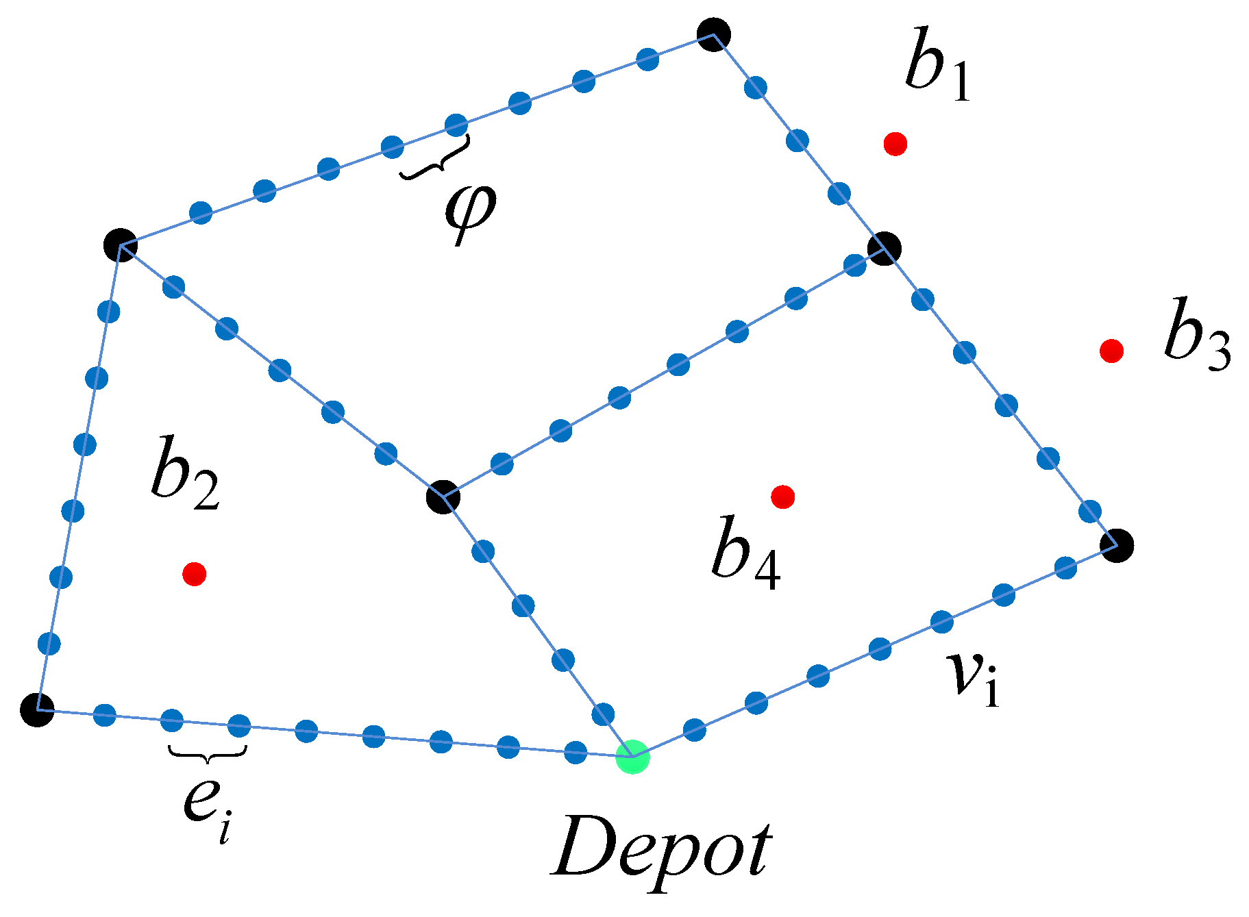
In addition, during the UAV delivery process, the UGV is driving on the road network. Considering the practical situation, the UGV cannot stop at any point of the road to release or recover the UAV, but it can release or recover it at some fixed points. Therefore, as shown in Figure 2, the road network is cut appropriately based on these fixed points in this study. A temporary docking point strategy is proposed for MOHRDS in this section. Figure 2 shows an undirected topological graph G = ( V , E ) which based on this strategy, where the road network is cut according to the accuracy φ , the cut points are stored in V = [ v 1 , v 2 , v n ] and the edges of the predefined road network are stored in E = e i , j , i , j . The adjacency matrix l 0 , 1 n × n is then introduced, where l i , j = 1 indicates the presence of an undirected edge e i , j connecting vertices v i and v j , otherwise, l i , j = 0 . Finally, the weight W i , j is defined as the Euclidean distance d i , j between the vertex v i and v j .
W i j = d i j , l i j = 1 , l i j = 0
As shown in Figure 2, the temporary docking point strategy denotes v i , i = 1 n as the point for the UGV to release or recover the UAV. F i , j 0 , 1 m × m is defined as the UAV sorties, where F i , j = 1 indicates the UAV continuously visits customers i to j in the delivery sequence P. v k is defined as the UAV’s release point T k , i , which is the closest point in V = [ v 1 , v 2 , v n ] to customer i when F i , j = 1 . Similarly, v k is defined as the UAV’s recovery point L j , k , which is the closest point in V = [ v 1 , v 2 , v n ] to customer j when F i , j = 1 . The temporary docking point strategy ensures delivery safety while making full use of the UAV’s endurance.

2.2. Definition of a New Delivery Customers Satisfaction

In the new global economy, customer satisfaction is highly valued as it is crucial to understand customer perceptions and evaluations. In the field of express delivery, customer satisfaction is related to whether the customers are served within their expected delivery time windows. However, the simple concept of time windows does not represent the CS well [20]. Therefore, this study is a deeper investigation of the previous time windows. According to expectancy theory, as the delivery time approaches the customer’s expected timeframe, satisfaction increases rapidly, reflecting the characteristics of a convex function [21]. Conversely, in accordance with the economic principle of diminishing marginal utility, as the delivery time approaches the customer’s final tolerance limit, their tolerance for delays decreases significantly, resulting in a faster decline in satisfaction. This aligns with the behavior of a concave function [22]. Based on these insights, a new customer satisfaction (CS) model for delivery time is introduced in this section. The membership function of CS is illustrated in Figure 3.
This membership function reflects the customers’ satisfaction and changes the classical hard time window S T i , E T i to the quadruple M S T i , S T i , E T i , M E T i . The vector S T i , E T i explains the soft time window and that its violation causes customer dissatisfaction; vector M S T i , M E T i explains the hard time window and that its violation makes the problem infeasible. Of course, time windows may sometimes be violated for economic, operational, or even environmental causes [23]. The CS function of customer b i is defined by the membership function as follows:
δ ( i ) = 0 ,   t i < M S T i t i M S T i S T i M S T i 2 ,   M S T i t i < S T i 1 ,   T i t i < E T i 1 t i E T i M E T i E T i 2 ,   E T i t i M E T i 0 ,   t i > M E T i
where t i is the time for the UAV to arrive at customer b i , M S T i is the earliest delivery time acceptable to the customer, S T i is the preferred start time for delivery, E T i is the time at which the customer starts to feel dissatisfied, and M E T i is the final delivery time that the customer can tolerate.
The CS function is a piecewise-linear function in that the function shape is subjected to the tightness of the time between two adjacent points of the vector. So, if a customer is served at its desired time window S T i , E T i , the grade of satisfaction is 1; otherwise, the degree of satisfaction gradually decreases along with the increase in the difference between the UAV’s arrival time and desired times.

2.3. Route Scheduling Model for MOHRDS

Following the preceding discussions, to optimize both CS and delivery costs under road network constraints, a route scheduling model for a Multi-objective Heterogeneous Robotic Delivery System (MOHRDS) is constructed in this section. In order to facilitate the modeling process, it is stipulated that both the UAV and the UGV travel at a constant speed. Furthermore, the time required for the UAV to take off and land vertically, as well as the time spent serving each customer, can be considered negligible. The model encompasses two objective functions: minimizing travel distance and maximizing customer satisfaction. Additionally, various constraints are considered, such as the UAV s limited endurance and payload capacity, time window restrictions, and ground traffic conditions. The corresponding symbols of MOHRDS are shown in Table 1. These symbols represent different variables and parameters used to describe various aspects of the problem.
Furthermore, which customer is served, which route each vehicle is taken, and which temporary docking points are utilized are determined by the decision variables. Therefore, there are five decision variables in the proposed model. The first decision variable in Equation (3) represents the service status of the customer. The second decision variable in Equation (4) represents the path of the UAV. The last three decision variables in Equations (5)–(7) represent the usage of temporary docking points.
R x , y = 1 , if the x - th customer point is visited on the y - th delivery in sequence P 0 , otherwise
F i , j = 1 , if the UAV continuously access customer points p i and p j 0 , otherwise
T k , i = 1 , if the UAV takes off from temporary docking point k to visit customer p i 0 , otherwise
L j , k = 1 , if the UAV flies from customer p j to temporary docking point k to land on the UGV 0 , otherwise
C i , j = 1 , if the UGV travels from point i to point j 0 , otherwise
The mathematical model for MOHRDS route scheduling proposed in this study is constructed as follows:
min f 1 = i M j M F i , j D i , j + a + b + i N j N C i , j Δ i , j a = k N T k , i v k p i b = k N L j , k v k p j
max f 2 = i M δ ( i )
Subject to
i = 1 N T i , j 1 , j M
j = 1 N L i , j 1 , i M
x = 1 M R x , y = 1 , y M
y = 1 M R x , y = 1 , x M
i = 1 m j = m M F i , j = 1 , m M
k = 1 N T k , i j = 1 M F i , j = 0 , i M
i = 1 M F i , j k = 1 N L j , k = 0 , j M
i = 1 n L j , i T i , j 0 , n N , j M
i = 1 n T i , j + 1 L j , i 0 , n N , j M 1
k = 1 N T k , i a + k = 1 N L j , k b + D i , j F i , j E
F i , j a = i j q a Q , i M , j M
1 v u k = 1 N T k , i a + k = 1 N L j , k b + D i , j Δ k , k v c a = v k p i , b = v k p j , i M , j M
j = 1 N C i , j = 1 , i = S
j = 1 N C i , j = k = 1 N C k , l i = S , l = S
t i = t i 1 + D k , k D k , k v c v c if D k , k = 1 t i 1 + v k p i v k p i v u v u if T k , i = 1 or L j , k = 1 t i 1 + D i , j D i , j v u if F i , j = 1 v u if F i , j = 1 t 0 = 0 , k , k [ S , N ] , i , j M
where Equations (8) and (9) are the objective functions, Equations (10) and (11) are the constraints between the UGV and the UAV, Equations (12)–(20) are the constraints of the UAV, and Equations (21) –(23) are the constraints of the UGV, the specific meaning is as shown in Table 2.
In the above model, the constraints of the road network, the UAV energy and load are considered, and CS and the delivery distance of MOHRDS are taken as the optimization objective of the route scheduling model simultaneously. Therefore, the delivery scheme obtained by solving the model takes into account customer satisfaction and delivery costs, which is more in line with the actual needs of express companies.

3. Modified Artificial Bee Colony Algorithm for the Problem

The artificial bee colony algorithm (ABC) is recognized as a probabilistic algorithm used to seek approximate optimal solutions [24]. It has been successfully applied in various fields, including the Traveling Salesman Problem (TSP) [25], image processing [26], logistics and path planning [27]. Notably, the convergence of the ABC algorithm has been rigorously proven [28]. Due to its effectiveness and proven convergence, the ABC algorithm is chosen as the route scheduling method for MOHRDS in this study. Two critical modifications of ABC are proposed in this section: discretization and multi-objective optimization. Regarding discretization, the original position update formula is replaced with a neighborhood search strategy to improve the convergence accuracy of the algorithm. In addition, a local search strategy based on rolling optimization is introduced to prevent the algorithm from falling into a local optimum. On the other hand, inspired by the Non-dominated Sorting Genetic Algorithm II (NSGA-II), a fast non-dominated sorting of solution individuals is performed to generate non-dominated solutions. A food source evaluation strategy is designed based on dominance strength and crowding distance to improve the diversity of optimal Pareto frontier solutions.

3.1. Overview of the ABC

ABC is a biological optimization method that simulates the intelligent search behavior of a swarm of bees. The algorithm finds the optimal food source through the collaborative efforts of three types of bee colonies. Like most bionic algorithms, the ABC consists of two processes: global exploration and local exploitation. The initialization phase and the scout bee phase perform random initialization of bees for global exploration with the following formula:
x i j = x j min + R × ( x j max x j min )
Equation (25) represents the process of random initialization for the j-th dimension of the i-th individual, where R is a random number between [ 0 , 1 ] , x j min and x j max represent the minimum and maximum values of the j-th dimension.
The local exploitation of the ABC mainly occurs during the employed bee phase and the onlooker bee phase, where the exploitation process is achieved through information exchange with a randomly selected individual. The formula is as follows:
x i j * = x i j + R × ( x i j x k j )
Equation (26) represents the local exploitation process of the j-th dimension of the i-th individual, where k i , R [ 1 , 1 ] .
Furthermore, in the roulette wheel selection of ABC, it is necessary to evaluate the quality of each food source in advance. The fitness value is calculated as Equation (27):
f i t i = 1 / ( 1 + o b j i ) , o b j i 0 1 + o b j i , o b j i < 0
where o b j i is the objective function value of the i-th individual.
The onlooker bee is chosen based on the fitness value of food sources. The higher the fitness value, the greater the probability of being selected. Therefore, this selection method can be formulated as Equation (28):
p i = f i t i i = 1 S N f i t i
where p i represents the selection probability, f i t i is the fitness value of the candidate solution X i , and S N stands for the number of food sources.

3.2. Discretization of the ABC

Due to the discrete nature of the MOHRDS route scheduling problem, traditional ABC cannot search in the discrete solution space, thus ABC is discretized in this study. The following three steps are performed during the discretization process to ensure that ABC can search efficiently in the discrete solution space: (1) encoding and decoding, (2) position updating strategy, and (3) local search strategy, which is specified in Section 3.2.1, Section 3.2.2 and Section 3.2.3, respectively.

3.2.1. Encoding and Decoding

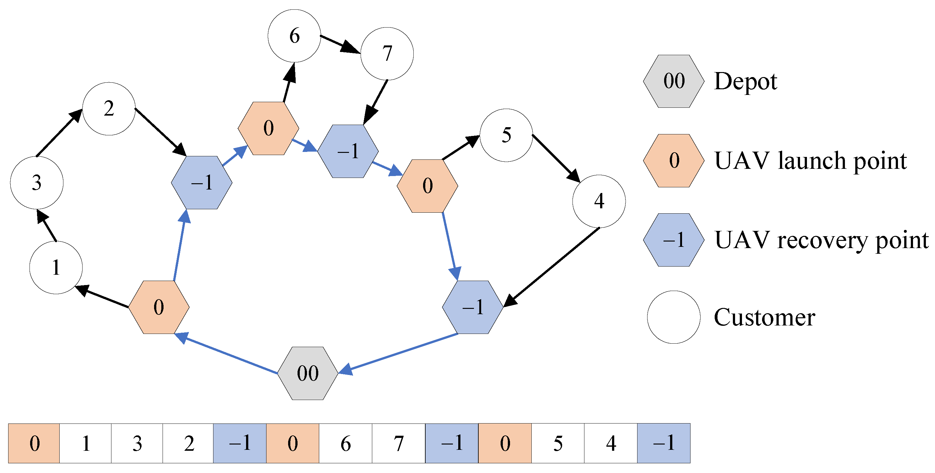
The encoding and decoding method of solutions is crucial in algorithm design, as it determines how the solution space is represented and how efficiently the algorithm can search. In this section, an integer encoding method is adopted to encode the solutions, based on the delivery sequence of customers, as illustrated in Figure 4. The continuous variables are converted into discrete variables by the encoding method to search in the discrete solution space. Meanwhile, the decoding rules are designed based on the proposed temporary docking point strategy to improve the solution efficiency of the algorithm. It can transform the solution into the corresponding transport route, as shown in Figure 5. The calculation process of the decoding method is as follows:
  • The UGV departs from depot S, carrying the UAV, and selects the temporary stopping point v k closest to the first customer b i in the decoded individual as the launch point T k , i for the UAV. It then checks if the constraints are satisfied. If the conditions are not met, a penalty is applied.
  • Iterate through the remaining customers until the current customer b j does not meet the endurance or payload constraints. Then, return to the previous customer b j 1 and find the closest temporary stopping point v k to it as the recovery point L j 1 , k for the UAV. It checks if the constraints are satisfied. If the conditions are not met, a penalty is applied.
  • Remove the customers before b j from the solution individual. If there are still unvisited customers remaining in the solution individual, go back to Step 1. Otherwise, proceed to Step 4.
  • At this point, all customers have been visited, indicating that all the missions of the UAV have been determined. The UGV, carrying the UAV, returns to depot S. As shown in Figure 5, both UGV and UAV paths are recorded. The total distance traveled by UGV and UAV is calculated based on Equations (8) and (9), and the overall customer satisfaction is evaluated.

3.2.2. Position Updating Strategy

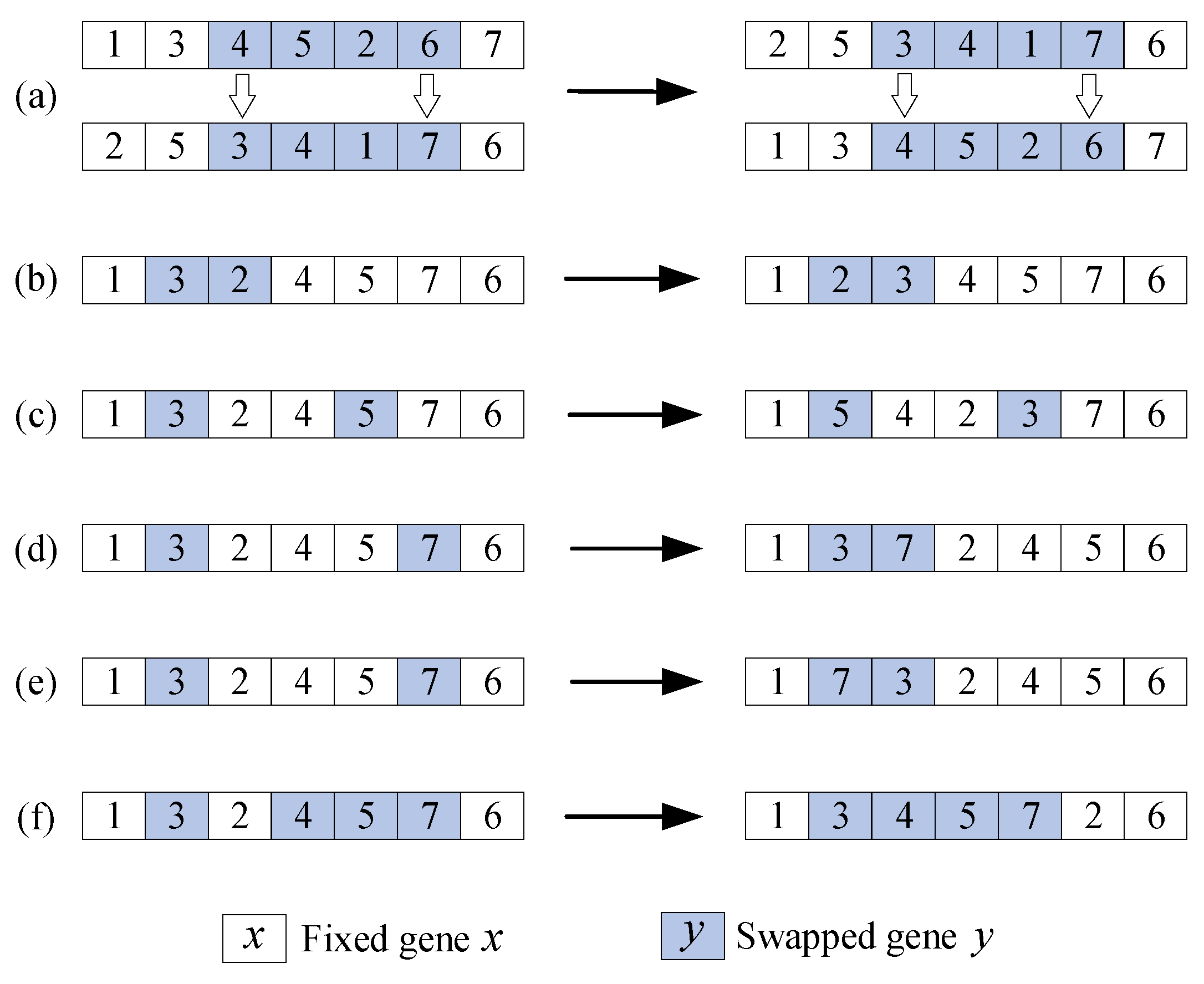
The path planning problem addressed in this study is of a highly intricate nature, encompassing the calculation of customer delivery sequences, the routing of UGV across the road network, and the selection of UAV and UGV releasing/recovering points. In order to enhance the efficacy of the ABC algorithm for this challenge, this section proposes a novel position update strategy. Furthermore, aiming at the defect of the ABC which is easy to fall into local optimum due to the lack of communication among the same kind of bees, a variety of neighborhood search operators in the position update phase of the ABC is introduced in this study to explore the solution space as much as possible [29,30,31,32]. Figure 6 illustrates all the neighborhood search operators used in ABC, and the specific are as follows:
  • The Partial-Mapped Crossover (PMX) operator is an efficient and widely used crossover operator, especially for permutation optimization problems. The PMX operator cross-combines the gene information of the two parent individuals during the crossover process to generate a new offspring individual, which retains the chromosome structure of the parent individual and ensures that no gene will be lost in the offspring. PMX is introduced to avoid premature convergence to local optimal solutions in this section.
  • Random Customer Exchange Mutation (RCEM) is a mutation operator with strong local search capability. RCEM can effectively explore the local solution space by exchanging elements within the neighborhood of the solution, thus helping to find the locally optimal solution. Due to the lack of convergence of the initial position update strategy, RCEM is introduced in this section to improve the local search capability of the algorithm.
  • Random Customer Reversal Mutation (RCRM) is a mutation operator with strong disturbance. By inverting a part of the current solution, this operator is able to break the local structure of the original solution and thus explore new solutions in the search space. Due to the poor perturbation of the initial location update strategy, RCRM is introduced in this section to improve the diversity of the population.
  • Random Customer Transfer Mutation (RCTM) is a mutation operator with simple strategy and good exploration ability. By inserting elements, RCTM can change the structure of the solution and increase the diversity of solutions to avoid falling into a local optimal solution. RCTM is introduced in this section to improve the possibility of finding the global optimal solution.

3.2.3. Local Search Strategy

The basic ABC algorithm suffers from the issue of strong exploration capability but weak exploitation capability [33]. Furthermore, the solution space under consideration in this paper is subject to a number of complex constraints, which serves to compound the challenge of searching with the ABC algorithm. In order to address this issue, a local search strategy is introduced to the ABC algorithm in this section, aiming to enhance its local exploitation capabilities and improve overall search efficiency.
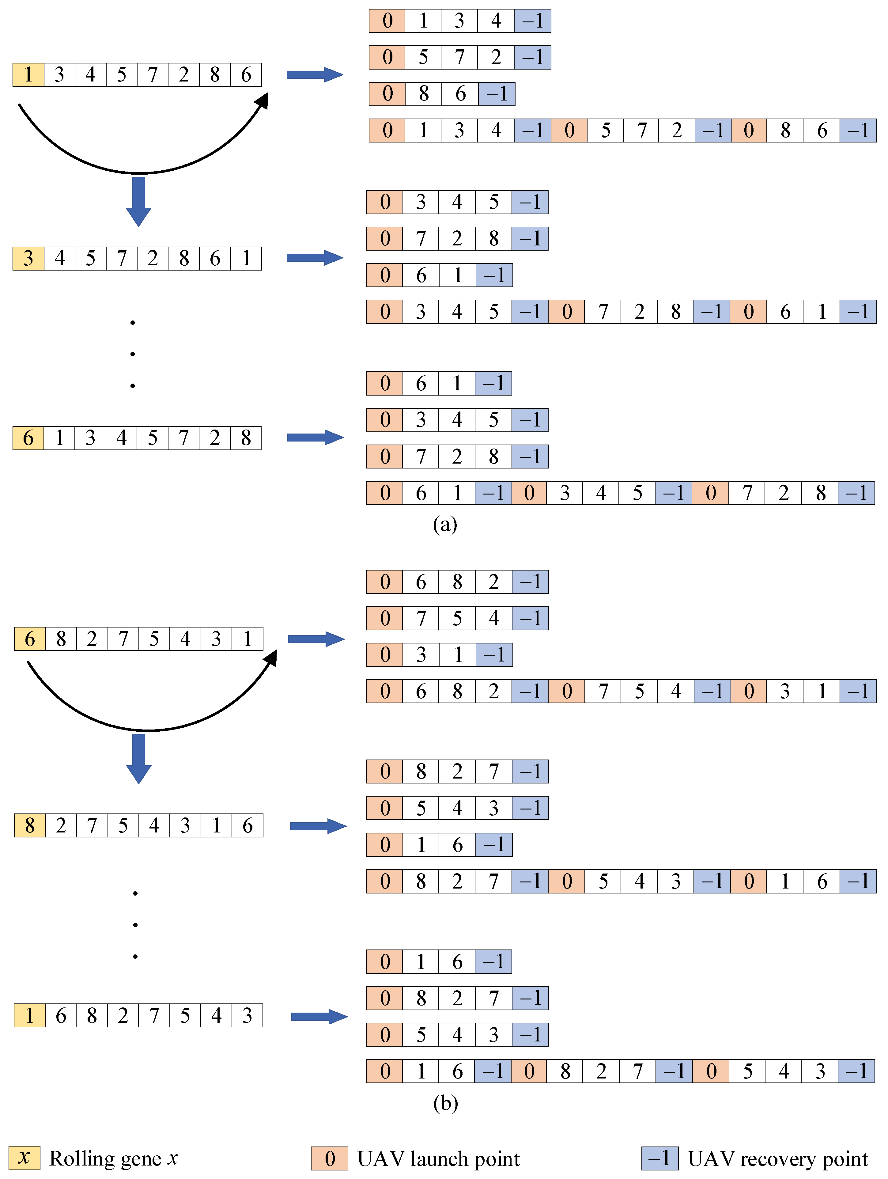
The rolling optimization method is introduced in the local search strategy to reduce the range of solution space, as depicted in Figure 7.
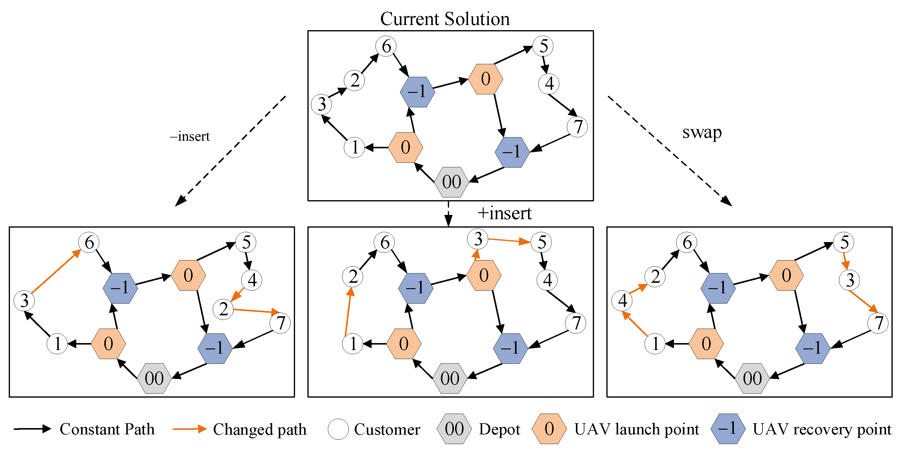
Furthermore, to improve the local exploitation capability of the algorithm, six local search operators are designed in this section [20,34,35,36]. As shown in Figure 8 and Figure 9, these operators are designed for searching within and between UAV sorties, respectively.
(i) Search operators within UAV sorties:
2-opt: Randomly select two customers, b i and b j , within the UAV sortie F i , j , and reverse the order of the customers between b i and b j to obtain a new offspring solution.
Exchange: Randomly select two customers, b i and b j , within the UAV sortie F i , j , and swap their positions to obtain a new offspring solution.
Insert: Randomly select two customers, b i and b j , within the UAV sortie F i , j , and insert customer b j before customer b i , resulting in a new offspring solution.
(ii) Search operators between UAV sorties:
±insert: Randomly select two customers b i and b j from two UAV sorties F i , j 1 and F i , j 2 . Insert customer b j before (or after) customer b i , resulting in a new offspring solution.
Swap: Randomly select two customers b i and b j from two UAV sorties F i , j 1 and F i , j 2 . Swap the positions of customer b i and customer b j , resulting in a new offspring solution.

3.3. Multi-Objective Improvement of the ABC

Most of the previous studies weighted multiple objectives into one optimization objective. However, when the delivery requirements of express companies for HRDS change, the weights of different goals need to be adjusted again. It cannot meet the real-time demand of express delivery. Therefore, it is better to support multi-alternative non-inferior solutions for MOHRDS route scheduling problems. But there are two problems that should be solved to extend ABC to multi-objective ABC: (1) how to generate non-dominated solutions in the process of population evolution and constitute the optimal Pareto front; (2) how to choose the better solution in the onlooker bee phase. In this section, the fast non-dominated sorting method and a new food source evaluation strategy are introduced to solve these problems, and the specific processes are given in Section 3.3.1 and Section 3.3.2, respectively.

3.3.1. Acceptance Criteria

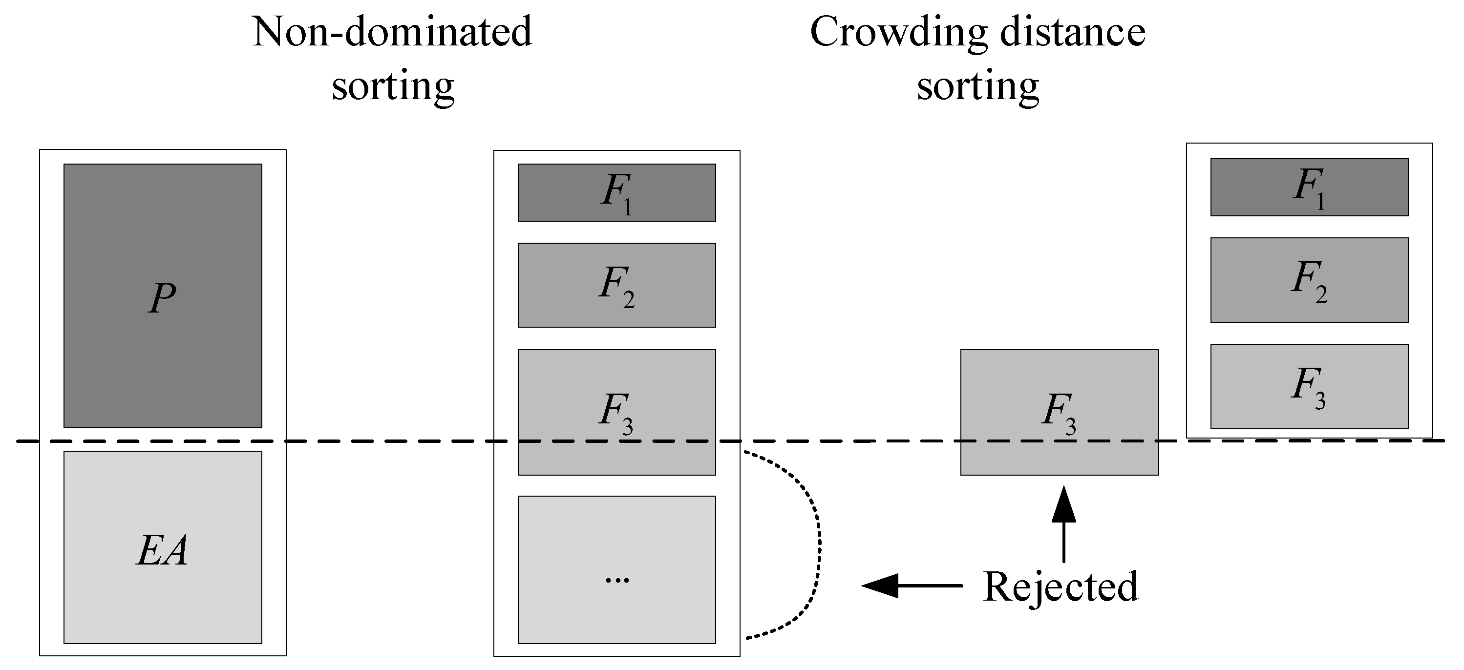
The traditional greedy-based acceptance criterion in ABC cannot generate non-dominated solutions, so in order to obtain the optimal Pareto front, a new acceptance criterion based on the external archiving method and the fast non-dominated sorting method is proposed in this section [37].
In this acceptance criterion, as shown in Figure 10, it is first assumed that K offspring solutions are generated by neighborhood search on parent solutions, and these offspring solutions are added to the external archive E A . Then, the fast non-dominated sorting method is used to sort between each parent solution α and its generated offspring solutions to obtain a set of mutually non-dominated solutions. The solution with the largest crowding distance in the Pareto front is selected as the new solution to improve the diversity of solutions, and compared with the dominance strength of α to judge whether it is necessary to update. The value of the l i m i t is recorded according to the updated times. In addition, in order to enhance the convergence speed of the algorithm, after all the solutions in the population P are updated, the fast non-dominated sorting method is used in the mixed population of P and E A , and the solution set equal to the number of solutions in P is selected as the updated population P n e w .

3.3.2. Food Source Evaluation Strategy

Multi-objective optimization problems do not have a fixed evaluation criterion regarding the merit of the solution due to the competition between the objective functions. This poses a challenge for the selection of onlooker bees in ABC. As shown in Figure 11, an evaluation strategy based on dominance strength and crowding distance is proposed in this section to solve the selection problem of the onlooker bee phase and improve the diversity of solutions [38]. Firstly, the dominance relationship is defined by Equation (29), the population is partitioned into several mutually disjoint subsets.
S 1 = { a S : b S , s . t : a b } S 2 = { a S S 1 : b S S 1 , s . t : a b } S i = { a S j = 1 i 1 S j : b S j = 1 i 1 S j , s . t : a b }
Then, for each solution θ in the set S l , l [ 1 , i ] , its dominance strength value is defined as follows:
s t r e n g t h ( θ ) = ( 1 l l i i ) + 1 1 i i , θ S l
The elements in the first layer have the highest dominance strength value and then decrease with 1 / i successively to ensure the superiority of non-dominated solutions.
In addition, the probabilities of finding new solutions near different solutions in the same dominance level are different. To increase the diversity of solutions and improve the population distribution, the crowding distance is introduced in this section when calculating selection probabilities. First, the boundary value n O b j × 1.0001 for the crowding distance is defined as the maximum value, where n O b j represents the number of optimization objectives. The value of the crowding distance needs to be controlled within the range of ( 0 , 1 1 i i ) to ensure the dominant strength is given higher priority when selecting individuals. The calculation is shown in Equation (31):
d ( θ ) = k = 1 n O b j f k ( θ 1 ) f k ( θ + 1 ) f k max f k min n O b j × 1.0001 × i
where f k θ denotes the k-th objective function value of the θ -th individual, f k max represents the maximum value of the k-th objective function, and f k min represents the minimum value of the k-th objective function.
After defining the two evaluation criteria, dominance strength and crowding distance, the fitness value of an individual is calculated according to Equation (32).
f i t n e s s ( θ ) = s t r e n t h ( θ ) + d ( θ )
Finally, during the onlooker bee phase, the roulette wheel selection method was used to select individuals in the population. Based on the obtained fitness values, the probability of an individual being selected is defined as follows:
P ( θ ) = f i t n e s s ( θ ) i = 1 S f i t n e s s ( θ i ) ( θ , θ i S )
The above definition not only ensures that the selection probability of a dominated individual is smaller than the selection probability of all individuals dominating it, but also satisfies that the sparser the distribution of other individuals around a non-dominated individual, the higher the selection probability.
In summary, the flowchart of the proposed NSABC (Non-dominated Sorting ABC) algorithm is illustrated in Figure 12.

4. Simulations Validation

This section presents an evaluation study to assess the performance of the proposed NSABC algorithm. We conducted a simulation analysis on a computer equipped with an R9-5000 CPU and 16 GB of RAM using MATLAB R2022a.

4.1. Prerequisite Knowledge

4.1.1. Algorithms for Comparison

To verify the superiority of the proposed NSABC algorithm, this section compares it with the NLNSABC (No Local-search NSABC) algorithm and the NSGA-II. NLNSABC is a simplified version of the proposed NSABC in this study, which lacks the local search strategy. The NSGA-II is a classical multi-objective heuristic algorithm widely used in various fields, such as the TSP and the Vehicle Routing Problem (VRP) [39,40].

4.1.2. Algorithm Performance Metrics

For multi-objective optimization problems, decision-makers aim to achieve high accuracy, good diversity, and even distribution in the optimal Pareto front. Therefore, to quantitatively analyze the role of the proposed NSABC algorithm in MOHRDS route scheduling, three performance metrics are of particular interest to us [41].
(i) Quality Metric (QM): Mixing the optimal Pareto front solutions obtained by different algorithms, identifying the non-dominated solutions among them, and calculating the proportion of non-dominated solutions for each algorithm.
(ii) Spacing Metric (SM): The calculation method for this performance metric is as follows:
S M = t = 1 N 1 d m e a n d i ( N 1 ) × d m e a n
where d i represents the Euclidean distance between the obtained non-dominated solution i and its adjacent non-dominated solution ( i + 1 ) , and d m e a n is the average value of all d i . This metric measures the uniformity of the obtained non-dominated solutions.
(iii) Edge Convergence (EC): The calculation method for this performance metric is as follows:
E C = 0.01 × c o s t + c s
where c o s t is the minimum travel distance in the optimal Pareto front and c s is the reciprocal of the maximum customer satisfaction in the optimal Pareto front. This performance metric measures the convergence of the boundaries of the multi-objective algorithm. Undoubtedly, a smaller value indicates better convergence of the algorithm.
Additionally, the concept of Pareto optimality is only the first step in solving multi-objective optimization problems. Subsequent decisions need to be made regarding the selection of a delivery plan. To provide decision-makers with more detailed reference solutions, this section defines the calculation of an optimal compromise solution in addition to the minimum delivery cost and maximum customer satisfaction solutions:
f ( i ) = c o s t ( i ) a v s ( i )
where f ( i ) is the ratio of delivery cost c o s t ( i ) to average customer satisfaction a v s ( i ) of the i-th solution in the optimal Pareto front.

4.2. Simulation Analysis

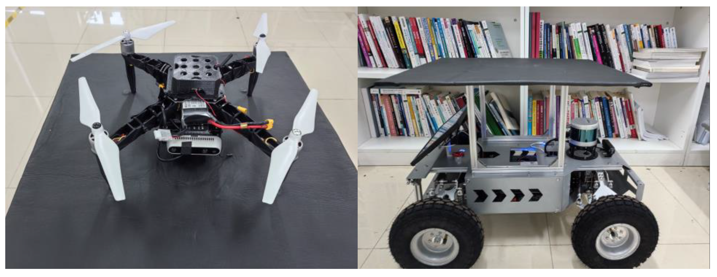
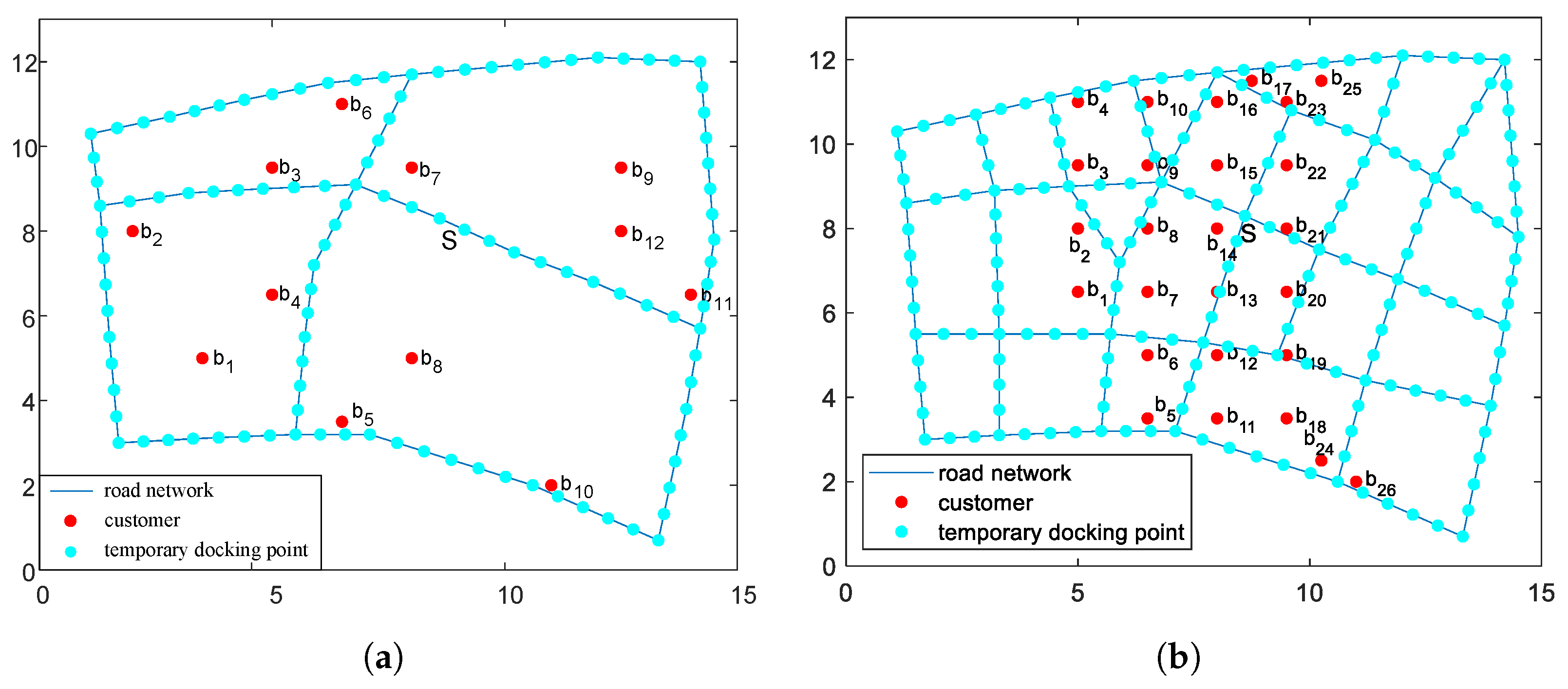
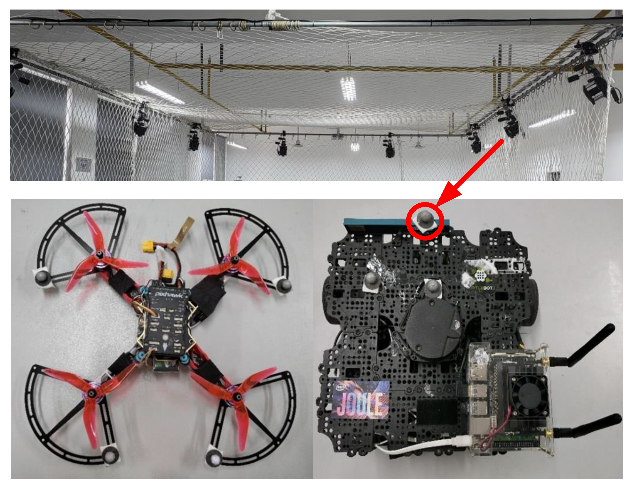
In this section, data selection and extension were conducted based on the actual parcel delivery situation in a 15 km × 13 km area of Wuhan city, as depicted in Figure 13. The settings of the relevant parameters used are presented in Table 3, with the UAV speed derived from the modified DJI S300 and the UGV speed derived from the custom-built Ackermann vehicle (see Figure 14). The evaluation study consists of three experiments to validate the performance of the proposed NSABC algorithm that simulates a simple road network, a complex road network and tight time windows. The simple road network is a polygon surrounded by 15 path segments, consisting of 12 customers to be served and 110 temporary docking points, as depicted in Figure 15a. MOHRDS starts from the depot, performs package delivery tasks and returns to the depot after servicing all customers. The complex road network consists of 51 path segments, 26 customers to be served and 192 temporary docking points, shown in Figure 15b. MOHRDS starts from the depot to perform delivery tasks, with thousands of possible routes for MOHRDS to service all customers and return to the depot. Meanwhile, this section defines a method for calculating the degree of overlap between customer time windows to represent better the possibility of satisfying customers’ demands under conflicting requirements. It conducts simulation analysis on time windows with different degrees of overlap.

4.2.1. Simple Road Network

The simple road network is shown in Figure 15a and the customer demands and locations are provided in Table 4. The problem is solved by NSABC proposed in this study, and a set of mutually non-dominated delivery schemes are obtained. In order to provide a reference for the decision maker, as shown in Figure 16, three reference solutions are provided: the maximum customer satisfaction solution, the shortest delivery distance solution, and the optimal compromise solution. The MOHRDS delivery paths are shown in Table 5.
Interestingly, the path solution of the optimal compromise solution is the same as the path with maximum customer satisfaction. When the express company needs to improve market competitiveness, the decision maker can focus on the maximum customer satisfaction scheme; when the express company needs to reduce operating costs, the decision maker can focus on the shortest route scheme; when the express company needs to maintain stability, the decision maker can focus on the optimal compromise scheme.
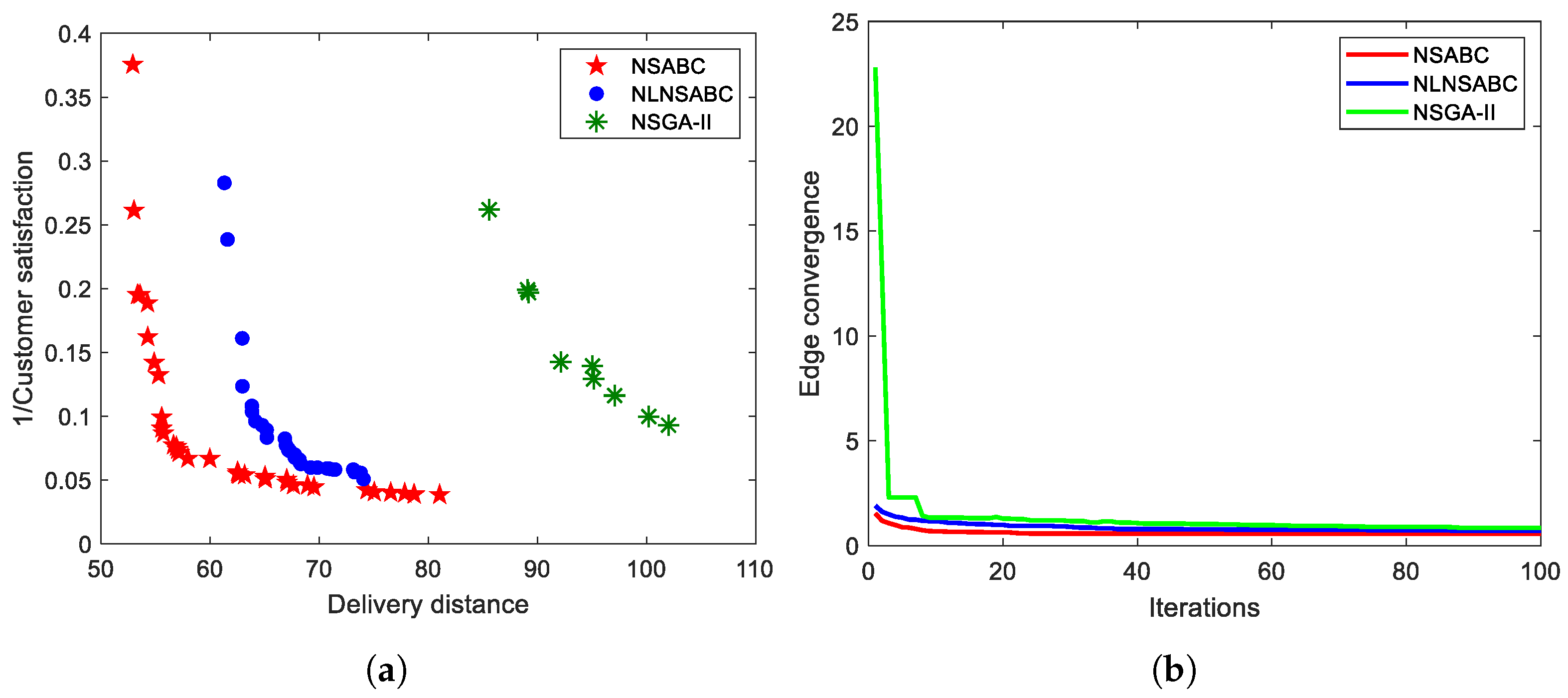
Furthermore, to verify the superiority of the NSABC algorithm, this section compares NSABC with NLNSABC and NSGA-II. Figure 17a shows the optimal Pareto fronts obtained by these three algorithms. The encoding and decoding strategies proposed in this study enable all three algorithms to solve the problem. However, it is difficult to compare their performance solely based on the Pareto fronts visually. Therefore, to validate the optimization performance and stability of NSABC, this section conducts ten repetitions for each experimental group and calculates the QM and SM values for each repetition, as shown in Table 6.
Table 6(a) shows that in a simple road network, compared to NLNSABC and NSGA-II, NSABC exhibits superior performance in both the quality and distribution of the obtained non-dominated solutions. It should be noted that although NLNSABC and NSGA-II achieve smaller SM values in the second, fourth, and seventh experiments, their Quality Metric falls short compared to NSABC. Furthermore, as shown in Figure 17b, the convergence of the EC values for the three algorithms is presented. The NSABC converges after eight iterations with an optimal EC value of 0.7382. The NLNSABC algorithm converges after 50 iterations with an optimal EC value of 0.7821. The NSGA-II algorithm converges after 77 iterations with an optimal EC value of 0.8000. The results indicate that the NSABC algorithm achieves high solution efficiency and fast convergence. It can be attributed to considering both dominance strength and crowding distance when calculating the selection probabilities and the utilization of local search strategy before the scout bees start working, enabling the swarm to discover the optimal delivery solutions more easily.

4.2.2. Complex Road Network

To validate NSABC’s ability to solve complex problems, the road network and customers are expanded in this section to form a complex road network as shown in Figure 15b. The customer demand, locations, and other information are provided in Table 7. The complex problem is solved by NSABC and three reference solutions are provided as shown in Figure 18. The MOHRDS delivery routes are shown in Table 8. Similar to the previous section, decision-makers can make choices based on the actual solutions.
Additionally, Figure 19a shows the optimal Pareto fronts obtained by the three algorithms in the complex road network environment, demonstrating that the Pareto front obtained by NSABC is superior to the other algorithms. To accurately illustrate the effectiveness of the proposed algorithm, each experiment in this section is repeated ten times, the QM and SM values for each experiment are calculated and presented in Table 6(b).
Table 6(b) shows the value of QM and SM is about the NSABC, the NLNSABC and the NSGA-II. In this study, the acceptance criterion enables NSABC to generate Pareto solutions, while the neighborhood search strategy and the local search strategy enhance the exploration space and convergence of NSABC, and obtain better QM values compared to other algorithms. The introduction of crowding distance makes the optimal Pareto front of NSABC have good diversity thus enhancing its SM value. As shown in Figure 19b, the convergence of the EC values for the three algorithms is presented. The NSABC converges at iteration 57, achieving the optimal EC value of 0.6394. The NLNSABC algorithm converges at iteration 92, with the optimal EC value of 0.7065. The NSGA-II algorithm converges at iteration 93, with the optimal EC value of 0.7463. These results demonstrate that the NSABC algorithm exhibits superior convergence speed and convergence performance in complex road network environments. Furthermore, the effectiveness of the proposed local search strategy in complex problems is also demonstrated.

4.2.3. Tight Time Windows

In practical package delivery processes, customers have varying widths of time windows. Some time windows are very tight, while others have minimal constraints. For this reason, this section introduces an overlap index to measure the tightness of customer-related time windows [42]. The formula for calculating the index value is as follows:
O v e r l a p I n d e x = i = 2 n j = 1 m ( β i α i ) ( β j α j ) n 1
where α i is the earliest time a customer can accept a service, while β i is the latest time a customer can be serviced. The higher the index, the tighter the time windows, resulting in more constraining sets to achieve customer satisfaction.
To validate the potential of NSABC in satisfying conflicting customer demands, this section extends the original customer time windows to a set of customers with significantly conflicting satisfaction requirements. The location and time information of the customers are provided in Table 9, and the overlap degree of the time windows for the two datasets is illustrated in Figure 20. Figure 20a represents the tight time windows corresponding to this section’s dataset, while Figure 20b shows the lenient time windows from the dataset in Section 4.2.2. As shown in Figure 21, the problem is solved by NSABC, which provides decision-makers with three reference solutions. The MOHRDS delivery paths are shown in Table 10.
In addition, the optimal Pareto fronts solved by the three algorithms are depicted in Figure 22a, and it is evident that NSABC maintains a dominant position in terms of the optimal Pareto front compared to the other two algorithms.
Table 6(c) shows that the NSABC algorithm still achieves superior non-dominated solution quality compared to NLNSABC and NSGA-II when dealing with highly conflicting time windows. NLNSABC and NSGA-II fail to converge to the optimal Pareto front obtained by NSABC. Although they exhibit better performance in terms of SM, the quality gap of the optimal Pareto front remains irreparable. As evident from the EC curves in Figure 22b, the NSABC algorithm converges at iteration 77 with the optimal EC value of 0.5675, while NLNSABC converges at iteration 90 with the optimal EC value of 0.7138, and NSGA-II converges at iteration 93 with the optimal EC value of 0.8458. These results indicate that the NSABC algorithm maintains efficiency and quality in solving the problem even with significant conflicts in customer time windows.

4.3. The Computational Complexity of NSABC

This section presents an analysis of the complexity of the NSABC algorithm, with a particular focus on its performance across different input sizes. This approach enabled the evaluation of the algorithm’s efficiency, performance, and potential advantages in a real-world scenario.
To ensure the reliability of the results, each set of experiments was repeated ten times. The results of the experiments are presented in Table 11. The data presented in the table illustrate the running time of the NSABC algorithm under two distinct road network scales: a simple road network comprising 110 temporary docking points and 12 customer points, and a complex road network comprising 192 temporary docking points and 26 points. The two types of road networks represent disparate input scales, thereby enabling a comparison of the algorithm’s performance in simple versus complex environments.
It can be observed that as NSABC progresses from handling simple road networks to more intricate ones, the running time increases by approximately 15% to 20%. This increase is considerably less pronounced than the expansion of the input size, which suggests that NSABC remains an efficient solution when dealing with large-scale data. When considering the context of package delivery, the low growth rate of NSABC implies that it is well-suited to handling an increasing number of customers while maintaining high operational efficiency in scenarios involving complex road networks and large customer bases.

5. Physical Experiments to Prove the Concept of the Model

To further validate the effectiveness and practicality of the above MOHRDS route scheduling method, this section will conduct physical experiments as a proof of concept based on the numerical simulation experiments in Section 4 for verification and analysis.

5.1. Setup of the Physical Experiment

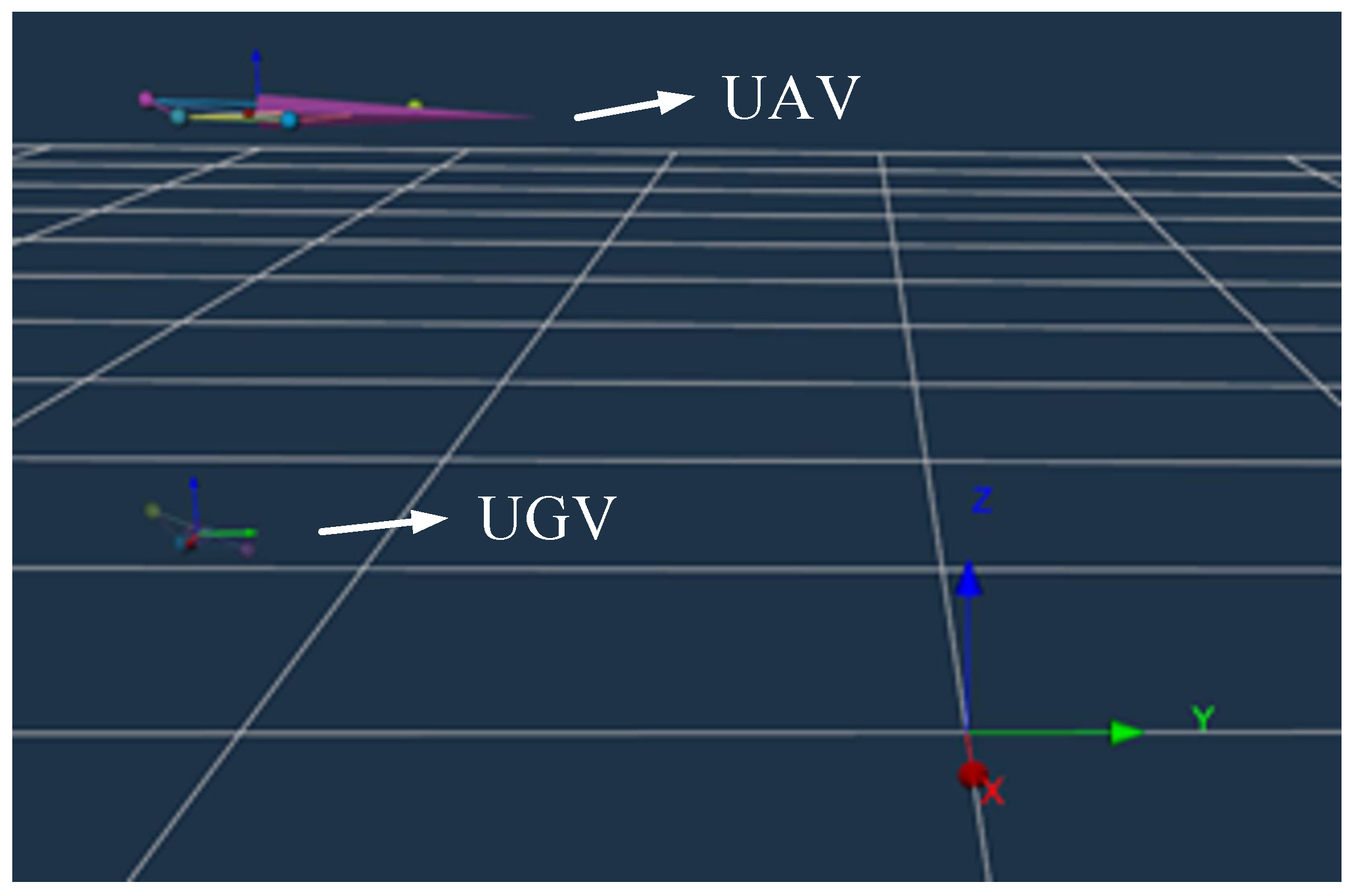
In this section, physical experiments on HRDS route scheduling are conducted using the scenario described in Section 4.2.2. The real environment used in the physical experiment is shown in Figure 23, with dimensions of 3 m × 5 m . To enhance UAV positioning accuracy, replace GPS with the NOKOV optical 3D motion capture system, which provides highly accurate position and posture measurements [43]. The experimental equipment is shown in Figure 24. In addition, in order to observe the HRDS movement trajectory more intuitively, this study has scaled down the complex road network used in the simulation experiments and simulated the experimental ground road network using tape on the floor. The 3D scene of the physical experimental platform is depicted in Figure 25.

5.2. Experimental Results and Analysis

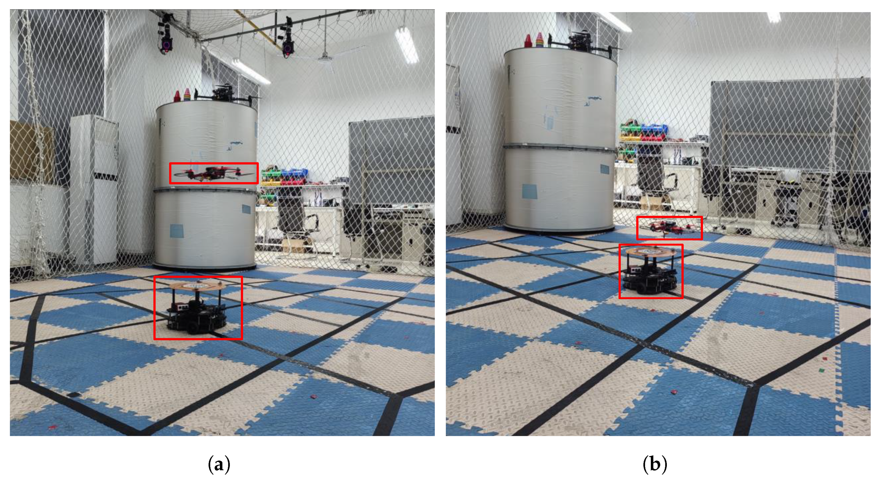
Physical experiments in this section are conducted using Figure 18a as an example. Figure 26a shows a physical shot of UAV and UGV separation during a mission: the UAV carries the package away from the UGV to perform delivery tasks, while the UGV moves to the next temporary stop point to provide replenishment. Figure 26b shows a physical shot of the UAV and UGV during a convergence. At this moment, the UAV is heading to the temporary stop point where the UGV has arrived early to perform replenishment operations. Once the replenishment is complete, the UAV will continue on to the next customer point, while the UGV will proceed to the next temporary stopping point. This cooperation between the UAV and the UGV ensures smooth delivery operations. More visualization results can be found at https://www.bilibili.com/video/BV1QYehenEZA/?vd_source=18395f0af87f302242f1ac8a71ac41fe; accessed on 25 July 2024.
This study employs the 3D coordinates of various points captured by the high-speed camera in the motion capture environment to ascertain the actual flight trajectory of four UAV flights and the driving trajectory of the UGV in the road network during the physical experiment. Figure 27 illustrates that the discrepancy between the actual flight trajectory of the UAV and the simulated path is minimal, and the UAV largely follows the simulated delivery path. The primary discrepancy between the actual flight trajectory of the UAV and the simulated path is that when the distance between the UAV and the target customer point is less than 10 cm, it is considered to have reached the customer point. Therefore, the deviation is within an acceptable range. Additionally, the deviation between the trajectory of the UGV and the road network is also minimal, without exceeding the road network range. Furthermore, the arc-shaped trajectory depicted in the figure is generated when the UAV and UGV change direction. The observation results indicate that the actual paths of the UAV and UGV are largely consistent with the simulated paths, thereby corroborating the reliability of the simulation experiment and attesting to the efficacy and viability of the model and algorithm proposed in this study.
Figure 28 illustrates the 3D coordinate variation curves of HRDS, with the vertical axis representing the corresponding axis position changes and the horizontal axis representing the running time. From the graph, it can be observed that the flight control system of the UAV is relatively stable, without significant jitter. Moreover, the 3D coordinate transformation curve of the UGV during the delivery process exhibits significant jitter in the z-axis direction, which can be attributed to the UGV’s bouncing caused by uneven ground. Throughout the entire HRDS delivery task, the UAV conducted a total of four landing replenishment operations and successfully completed the delivery task. These results indicate a high degree of precision in the path planning experiment, with minimal motion errors. This demonstrates the effectiveness and practicality of the algorithm designed in this study.
Table 12 presents a comparison between the simulated and actual motion path lengths of both the UAV and UGV. The results indicate that while there is some discrepancy between the actual path lengths of the UAV and UGV compared to the simulated experiment results, the error is generally around 10%, which remains within an acceptable range. In conclusion, the experimental error is relatively minor, largely aligning with the specifications of the HRDS delivery task path planning model described in this study. This outcome validates the accuracy of the model constructed in this study.

6. Conclusions

This study investigates a multi-objective heterogeneous robotic delivery system that considers constraints including UAV energy, payload capacity, ground road network, customer waiting time, and rendezvous time. The objectives of this study are to maximize customer satisfaction while minimizing delivery costs. A mathematical model for the route scheduling of MOHRDS is established, and the ABC is improved based on fast non-dominated sorting strategies to obtain the optimal set of delivery routes. Simulation experiments demonstrate that this method exhibits strong optimization capabilities and high computational efficiency and can obtain the optimal Pareto front for MOHRDS. Physical experiments further validate the feasibility and effectiveness of the proposed method.
The optimal Pareto front obtained in this study can provide various delivery plans for decision-makers and enhance the market competitiveness of express companies. However, the delivery system in this study is comprised of a single UAV and a single UGV. In order to expand the coverage of the delivery system and enhance its flexibility, future efforts will focus on exploring the coordinated delivery of multiple UAVs and multiple UGVs. On the other hand, the weight of the package can significantly affect the energy consumption of the UAV, which in turn, has a major impact on the planned route [44]. Consequently, future experiments will consider this as a crucial factor in achieving more realistic MOHRDS path planning.

Author Contributions

Conceptualization, Z.C.; Methodology, Z.C. and Z.W.; Software, S.H.; Investigation, Z.C.; Resources, Z.C., Y.C. and R.M.A.I.; Data curation, S.H.; Writing—original draft preparation, Z.W.; Writing—review and editing, S.H., Y.C., M.H. and R.M.A.I.; Visualization, S.H.; Funding acquisition, Z.C., Y.C., M.H. and R.M.A.I. All authors have read and agreed to the published version of the manuscript.

Funding

This research was funded by National Natural Science Foundation of China under Grant Nos. 62173262, 62073250, 62203339, and 62003249.

Data Availability Statement

The data presented in this study are available on request from the corresponding author.

Conflicts of Interest

The authors declare no conflicts of interest.

References

  1. Rodrigues, G.; Caldas, R.; Araujo, G.; de Moraes, V.; Rodrigues, G.; Pelliccione, P. An architecture for mission coordination of heterogeneous robots. J. Syst. Softw. 2022, 191, 111363. [Google Scholar] [CrossRef]
  2. Chen, Y.; Chen, M.; Chen, Z.; Cheng, L.; Yang, Y.; Li, H. Delivery path planning of heterogeneous robot system under road network constraints. Comput. Electr. Eng. 2021, 92, 107197. [Google Scholar] [CrossRef]
  3. Kumar, S.P.; Jat, D.; Sahni, R.K.; Jyoti, B.; Kumar, M.; Subeesh, A.; Parmar, B.S.; Mehta, C. Measurement of droplets characteristics of UAV based spraying system using imaging techniques and prediction by GWO-ANN model. Measurement 2024, 234, 114759. [Google Scholar] [CrossRef]
  4. Farrag, T.A.; Askr, H.; Elhosseini, M.A.; Hassanien, A.E.; Farag, M.A. Intelligent Parcel Delivery Scheduling Using Truck-Drones to Cut down Time and Cost. Drones 2024, 8, 477. [Google Scholar] [CrossRef]
  5. Mourelo Ferrandez, S.; Harbison, T.; Webwer, T.; Sturges, R.; Rich, R. Optimization of a truck-drone in tandem delivery network using k-means and genetic algorithm. J. Ind. Eng. Manag. 2016, 9, 374–388. [Google Scholar] [CrossRef]
  6. He, Y.; Wang, D.; Huang, F.; Zhang, R.; Min, L. Aerial-Ground Integrated Vehicular Networks: A UAV-Vehicle Collaboration Perspective. IEEE Trans. Intell. Transp. Syst. 2023, 25, 5154–5169. [Google Scholar] [CrossRef]
  7. Niu, G.; Wu, L.; Gao, Y.; Pun, M.O. Unmanned aerial vehicle (UAV)-assisted path planning for unmanned ground vehicles (UGVs) via disciplined convex-concave programming. IEEE Trans. Veh. Technol. 2022, 71, 6996–7007. [Google Scholar] [CrossRef]
  8. Bacheti, V.P.; Brandão, A.S.; Sarcinelli-Filho, M. A path-following controller for a uav-ugv formation performing the final step of last-mile-delivery. IEEE Access 2021, 9, 142218–142231. [Google Scholar] [CrossRef]
  9. Murray, C.C.; Chu, A.G. The flying sidekick traveling salesman problem: Optimization of drone-assisted parcel delivery. Transp. Res. Part Emerg. Technol. 2015, 54, 86–109. [Google Scholar] [CrossRef]
  10. Agatz, N.; Bouman, P.; Schmidt, M. Optimization approaches for the traveling salesman problem with drone. Transp. Sci. 2018, 52, 965–981. [Google Scholar] [CrossRef]
  11. Kitjacharoenchai, P.; Min, B.C.; Lee, S. Two echelon vehicle routing problem with drones in last mile delivery. Int. J. Prod. Econ. 2020, 225, 107598. [Google Scholar] [CrossRef]
  12. Wang, Q.; Chen, H.; Qiao, L.; Tian, J.; Su, Y. Path planning for UAV/UGV collaborative systems in intelligent manufacturing. IET Intell. Transp. Syst. 2020, 14, 1475–1483. [Google Scholar] [CrossRef]
  13. Rajesh, S.; Abd Algani, Y.M.; Al Ansari, M.S.; Balachander, B.; Raj, R.; Muda, I.; Bala, B.K.; Balaji, S. Detection of features from the internet of things customer attitudes in the hotel industry using a deep neural network model. Meas. Sens. 2022, 22, 100384. [Google Scholar] [CrossRef]
  14. Omar Ali, S.R.; Abd Hakim Amir, S.N. Service quality and customer satisfaction: Experience of customers in postal service. J. Intelek 2020, 15, 67–75. [Google Scholar] [CrossRef]
  15. Xu, Z.; Elomri, A.; Pokharel, S.; Mutlu, F. A model for capacitated green vehicle routing problem with the time-varying vehicle speed and soft time windows. Comput. Ind. Eng. 2019, 137, 106011. [Google Scholar] [CrossRef]
  16. Zhang, J.; Wang, W.; Zhao, Y.; Cattani, C. Multiobjective quantum evolutionary algorithm for the vehicle routing problem with customer satisfaction. Math. Probl. Eng. 2012, 2012. [Google Scholar] [CrossRef]
  17. Yan, X.; Xiao, B.; Zhao, Z. Multi-objective vehicle routing problem with simultaneous pick-up and delivery considering customer satisfaction. In Proceedings of the 2019 IEEE International Conference on Smart Manufacturing, Industrial & Logistics Engineering (SMILE), Hangzhou, China, 20–21 April 2019; pp. 93–97. [Google Scholar] [CrossRef]
  18. Zhang, Y.; Yuan, C.; Wu, J. Vehicle routing optimization of instant distribution routing based on customer satisfaction. Information 2020, 11, 36. [Google Scholar] [CrossRef]
  19. Ghannadpour, S.F.; Noori, S.; Tavakkoli-Moghaddam, R. Multiobjective dynamic vehicle routing problem with fuzzy travel times and customers’ satisfaction in supply chain management. IEEE Trans. Eng. Manag. 2013, 60, 777–790. [Google Scholar] [CrossRef]
  20. Zhang, H.; Zhang, Q.; Ma, L.; Zhang, Z.; Liu, Y. A hybrid ant colony optimization algorithm for a multi-objective vehicle routing problem with flexible time windows. Inf. Sci. 2019, 490, 166–190. [Google Scholar] [CrossRef]
  21. Hong, C.; Choi, E.K.C.; Joung, H.W.D. Determinants of customer purchase intention toward online food delivery services: The moderating role of usage frequency. J. Hosp. Tour. Manag. 2023, 54, 76–87. [Google Scholar] [CrossRef]
  22. Lebedev, D.; Goulart, P.; Margellos, K. A dynamic programming framework for optimal delivery time slot pricing. Eur. J. Oper. Res. 2021, 292, 456–468. [Google Scholar] [CrossRef]
  23. Afshar-Bakeshloo, M.; Mehrabi, A.; Safari, H.; Maleki, M.; Jolai, F. A green vehicle routing problem with customer satisfaction criteria. J. Ind. Eng. Int. 2016, 12, 529–544. [Google Scholar] [CrossRef]
  24. Karaboga, D.; Basturk, B. Artificial bee colony (ABC) optimization algorithm for solving constrained optimization problems. In Proceedings of the International Fuzzy Systems Association World Congress, Cancun, Mexico, 18–21 June 2007; pp. 789–798. [Google Scholar] [CrossRef]
  25. Choong, S.S.; Wong, L.P.; Lim, C.P. An artificial bee colony algorithm with a modified choice function for the traveling salesman problem. Swarm Evol. Comput. 2019, 44, 622–635. [Google Scholar] [CrossRef]
  26. Öztürk, Ş.; Ahmad, R.; Akhtar, N. Variants of Artificial Bee Colony algorithm and its applications in medical image processing. Appl. Soft Comput. 2020, 97, 106799. [Google Scholar] [CrossRef]
  27. Xu, F.; Li, H.; Pun, C.M.; Hu, H.; Li, Y.; Song, Y.; Gao, H. A new global best guided artificial bee colony algorithm with application in robot path planning. Appl. Soft Comput. 2020, 88, 106037. [Google Scholar] [CrossRef]
  28. Jiang, Y.; Qian, H.; Chu, Y.; Liu, J.; Jiang, Z.; Dong, F.; Jia, L. Convergence analysis of ABC algorithm based on difference model. Appl. Soft Comput. 2023, 146, 110627. [Google Scholar] [CrossRef]
  29. Xiao, S.; Wang, H.; Wang, W.; Huang, Z.; Zhou, X.; Xu, M. Artificial bee colony algorithm based on adaptive neighborhood search and Gaussian perturbation. Appl. Soft Comput. 2021, 100, 106955. [Google Scholar] [CrossRef]
  30. Wang, H.; Wang, W.; Xiao, S.; Cui, Z.; Xu, M.; Zhou, X. Improving artificial bee colony algorithm using a new neighborhood selection mechanism. Inf. Sci. 2020, 527, 227–240. [Google Scholar] [CrossRef]
  31. Ye, T.; Wang, W.; Wang, H.; Cui, Z.; Wang, Y.; Zhao, J.; Hu, M. Artificial bee colony algorithm with efficient search strategy based on random neighborhood structure. Knowl.-Based Syst. 2022, 241, 108306. [Google Scholar] [CrossRef]
  32. Xiao, W.S.; Li, G.X.; Liu, C.; Tan, L.P. A novel chaotic and neighborhood search-based artificial bee colony algorithm for solving optimization problems. Sci. Rep. 2023, 13, 20496. [Google Scholar] [CrossRef]
  33. Zhou, X.; Tan, G.; Wang, H.; Ma, Y.; Wu, S. Artificial bee colony algorithm based on multi-neighbor guidance. Expert Syst. Appl. 2024, 259, 125283. [Google Scholar] [CrossRef]
  34. Hakli, H.; Kiran, M.S. An improved artificial bee colony algorithm for balancing local and global search behaviors in continuous optimization. Int. J. Mach. Learn. Cybern. 2020, 11, 2051–2076. [Google Scholar] [CrossRef]
  35. Dumez, D.; Lehuédé, F.; Péton, O. A large neighborhood search approach to the vehicle routing problem with delivery options. Transp. Res. Part Methodol. 2021, 144, 103–132. [Google Scholar] [CrossRef]
  36. Masmoudi, M.A.; Mancini, S.; Baldacci, R.; Kuo, Y.H. Vehicle routing problems with drones equipped with multi-package payload compartments. Transp. Res. Part Logist. Transp. Rev. 2022, 164, 102757. [Google Scholar] [CrossRef]
  37. Deb, K.; Pratap, A.; Agarwal, S.; Meyarivan, T. A fast and elitist multiobjective genetic algorithm: NSGA-II. IEEE Trans. Evol. Comput. 2002, 6, 182–197. [Google Scholar] [CrossRef]
  38. Zitzler, E.; Laumanns, M.; Thiele, L. SPEA2: Improving the strength Pareto evolutionary algorithm. Tik Rep. 2001, 103. [Google Scholar] [CrossRef]
  39. Srivastava, G.; Singh, A.; Mallipeddi, R. NSGA-II with objective-specific variation operators for multiobjective vehicle routing problem with time windows. Expert Syst. Appl. 2021, 176, 114779. [Google Scholar] [CrossRef]
  40. Shuai, Y.; Yunfeng, S.; Kai, Z. An effective method for solving multiple travelling salesman problem based on NSGA-II. Syst. Sci. Control. Eng. 2019, 7, 108–116. [Google Scholar] [CrossRef]
  41. Chen, Z.; Wu, H.; Chen, Y.; Cheng, L.; Zhang, B. Patrol robot path planning in nuclear power plant using an interval multi-objective particle swarm optimization algorithm. Appl. Soft Comput. 2022, 116, 108192. [Google Scholar] [CrossRef]
  42. Elgharably, N.; Easa, S.; Nassef, A.; El Damatty, A. Stochastic multi-objective vehicle routing model in green environment with customer satisfaction. IEEE Trans. Intell. Transp. Syst. 2022, 24, 1337–1355. [Google Scholar] [CrossRef]
  43. Sheng, B.; Chen, L.; Cheng, J.; Zhang, Y.; Hua, Z.; Tao, J. A markless 3D human motion data acquisition method based on the binocular stereo vision and lightweight open pose algorithm. Measurement 2024, 225, 113908. [Google Scholar] [CrossRef]
  44. Saponi, M.; Borboni, A.; Adamini, R.; Faglia, R.; Amici, C. Embedded payload solutions in UAVs for medium and small package delivery. Machines 2022, 10, 737. [Google Scholar] [CrossRef]
Figure 1. Heterogeneous Robotic Delivery System.
Drones 08 00519 g001
Figure 2. Temporary docking points strategy.
Drones 08 00519 g002
Figure 3. Customer satisfaction function.
Drones 08 00519 g003
Figure 4. Encoding and Decoding.
Drones 08 00519 g004
Figure 5. Corresponding rules for routes.
Drones 08 00519 g005
Figure 6. Neighborhood search operators. (a) PMX. (b) RCEM. (c) RCRM. (d) RCTM ( + 1 ). (e) RCTM ( 1 ). (f) RCTM (−n).
Drones 08 00519 g006
Figure 7. Rolling optimization strategy. (a) Forward Rolling Search. (b) Reverse Rolling Search.
Drones 08 00519 g007
Figure 8. Local search operators within UAV sorties.
Drones 08 00519 g008
Figure 9. Local search operators between UAV sorties.
Drones 08 00519 g009
Figure 10. Acceptance criteria.
Drones 08 00519 g010
Figure 11. Food source evaluation strategy.
Drones 08 00519 g011
Figure 12. Flowchart of NSABC.
Drones 08 00519 g012
Figure 13. Satellite map of an area of Wuhan.
Drones 08 00519 g013
Figure 14. The actual UAV and UGV.
Drones 08 00519 g014
Figure 15. Topological map. (a) The simple topological map. (b) The complex topological map.
Drones 08 00519 g015
Figure 16. Delivery routes of MOHRDS under simple road network restriction. (a) The minimum delivery cost. (b) The maximum customer satisfaction. (c) The optimal compromise solution.
Drones 08 00519 g016
Figure 17. Simple road network simulation results. (a) Pareto front. (b) The EC curve.
Drones 08 00519 g017
Figure 18. Delivery routes of MOHRDS under complex road network restriction. (a) The minimum delivery cost. (b) The maximum customer satisfaction. (c) The optimal compromise solution.
Drones 08 00519 g018
Figure 19. Complex road network simulation results. (a) Pareto front. (b) The EC curve.
Drones 08 00519 g019
Figure 20. Time windows with different levels of overlap. (a) Tight time windows. (b) Loose time windows.
Drones 08 00519 g020
Figure 21. Delivery routes of MOHRDS under tight time windows restriction. (a) The minimum delivery cost. (b) The maximum customer satisfaction. (c) The optimal compromise solution.
Drones 08 00519 g021
Figure 22. Tight time windows simulation results. (a) Pareto front. (b) The EC curve.
Drones 08 00519 g022
Figure 23. The experimental scenario.
Drones 08 00519 g023
Figure 24. Experimental equipment.
Drones 08 00519 g024
Figure 25. The 3D scene.
Drones 08 00519 g025
Figure 26. The Collaboration Process between UAV and UGV. (a) Separation of the UAV and the UGV. (b) Convergence of the UAV and the UGV.
Drones 08 00519 g026
Figure 27. Comparison between simulated and real paths.
Drones 08 00519 g027
Figure 28. The coordinate change curve of UAV and UGV.
Drones 08 00519 g028
Table 1. Symbol explanation.
SymbolsDescription
E 1UAV endurance
QMaximum payload of the UAV
v u Flight speed of the UAV
v c Drive speed of the UGV
MNumber of customers
NNumber of temporary docking points
BSet of customers B = 1 , 2 , , M
AThe set A, consisting of customers B and temporary docking points V, in the
undirected graph G.
PThe sequence P of UAV delivering services to customers.
p i The i-th customer in the delivery sequence set P.
q i The weight of the i-th customer’s demand q i R , i = 1 , 2 , , M .
v k p i The flying distance between the customer point p i and the temporary docking point
v k for the UAV.
D i , j The flying distance between the customer points b i and b j for the unmanned aerial
vehicle (UAV) D i , j R , i = 1 , 2 , , M ; j = 1 , 2 , , M .
Δ k , k The driving distance between the vehicle’s temporary stopping points is v k and v k .
Δ k , k R , k = 1 , 2 , , N ; k = 1 , 2 , , N
1 E is the endurance limit of the UAV, and this constraint ensures the UAV’s flight distance doesn’t exceed its endurance based on Euclidean estimates.
Table 2. Equation meaning.
EquationsMeanings
Equation (8)Minimizing the total distance traveled by UGV and UAV
Equation (9)Maximizing the customer satisfaction
Equation (10)Indicate that each temporary docking point allows at most one takeoff for the UAV
Equation (11)Indicate that each temporary docking point allows at most one landing for the UAV
Equation (12)States that the UAV can only visit one customer at a time
Equation (13)Ensures that each customer is visited only once
Equation (14)Allows the UAV to serve multiple customers within one flight
Equation (15)Stipulates that the UAV starts the delivery immediately after takeoff
Equation (16)Requires the UAV to return to the UGV for replenishment immediately after completing the
delivery task
Equation (17)Ensures that the takeoff point for each flight of the UAV is before the landing point
Equation (18)Indicates that the UAV can only take off for the next flight after completing replenishment from
the previous flight
Equation (19)Restricts the UAV’s distance traveled within its endurance limit during the delivery task
Equation (20)Limits the weight of packages carried by the UAV to its capacity
Equation (21)Ensures that the UGV does not arrive at the landing point later than the UAV to facilitate timely
recovery and replenishment
Equation (22)States that each UGV is dispatched at most once
Equation (23)Represents the movement of UGV carrying UAV from the depot, and they return to the depot
after completing their tasks
Equation (24)Defines the calculation of the UAV’s arrival time at each customer
Table 3. Setting of parameters.
DescriptionValueDescriptionValue
Iteration count i t e r m a x = 100 The speed of the UAV v a = 60 km / h
Population size N p o p = 100 The speed of the UGV v g = 50 km / h
Number of employed bees N e m p = 100 The endurance of the UAV E = 20 km
Number of onlooker bees N o n l = 100 The payload capacity of the UAV Q = 20 kg
Number of stagnation iterations l i m i t = 60
Table 4. The information of customers with simple road network restriction.
No.LocationDemand (kg)Time WindowsNo.LocationDemand (kg)Time Windows
1 ( 3.5 , 5.0 ) 1 [ 77 , 79 , 83 , 85 ] 7 ( 8.0 , 9.5 ) 2 [ 25 , 27 , 31 , 33 ]
2 ( 2.0 , 8.0 ) 0.5 [ 8 , 10 , 14 , 16 ] 8 ( 8.0 , 5.0 ) 1 [ 62 , 64 , 68 , 70 ]
3 ( 5.0 , 9.5 ) 1 [ 1 , 3 , 7 , 9 ] 9 ( 12.5 , 9.5 ) 0.5 [ 38 , 40 , 44 , 46 ]
4 ( 5.0 , 6.5 ) 1 [ 20 , 22 , 26 , 28 ] 10 ( 11.0 , 2.0 ) 1 [ 66 , 68 , 72 , 74 ]
5 ( 6.5 , 3.5 ) 2 [ 60 , 62 , 66 , 68 ] 11 ( 14.0 , 6.5 ) 1.5 [ 35 , 37 , 41 , 43 ]
6 ( 6.5 , 11.0 ) 1.5 [ 3 , 5 , 9 , 11 ] 12 ( 12.5 , 8.0 ) 0.5 [ 29 , 31 , 35 , 37 ]
Table 5. The MOHRDS delivery routes with simple road network restriction.
SolutionRouteDelivery DistanceCustomer Satisfaction
the shortest delivery distance solutionUGV route:  S v 17 v 85 v 45 v 36 v 32 v 58 v 13 v 72
S
UAV route:  b 12 b 9 b 11 b 10 b 8 b 5 b 1 b 2 b 4 b 3
b 6 b 7
64.7335 km 0 %
the maximum customer satisfaction solutionUGV route:  S v 13 v 56 v 58 v 17 v 85 v 104 v 36 v 45
v 32 S
UAV route:  b 3 b 6 b 2 b 4 b 7 b 12 b 11 b 9 b 5 b 8
b 10 b 1
102.683 km 100 %
the optimal compromise solutionUGV route:  S v 13 v 56 v 58 v 17 v 85 v 104 v 36 v 45
v 32 S
UAV route:  b 3 b 6 b 2 b 4 b 7 b 12 b 11 b 9 b 5 b 8
b 10 b 1
102.683 km 100 %
Table 6. The comparison of NSABC algorithm, NLNSABC algorithm and NSGAII algorithm under different constraints.
(a) Comparison of Pareto solutions obtained using three algorithms under simple road network restriction
Trials12345678910
QMNSABC73.07792.30872.00072.00069.23196.15468.00010070.37096.296
NLNSABC50.00061.37944.00044.00042.30865.38548.00073.07748.14866.667
NSGAII65.38519.23148.00048.00050.0003.846248.000014.8153.7037
SMNSABC1.11391.11391.11391.11391.11391.11391.08211.11391.11391.1139
NLNSABC1.26401.21981.16101.07101.11411.54840.97141.31831.29441.1733
NSGAII1.61370.62541.44641.38821.67091.85121.98791.34521.29421.5175
(b) Comparison of Pareto solutions obtained using three algorithms under complex road network restriction
Trials12345678910
QMNSABC100100100100100100100100100100
NLNSABC0000000000
NSGAII0000000000
SMNSABC0.17240.34560.20750.34920.15850.29840.35630.33530.22090.2979
NLNSABC0.49851.02220.51190.56770.68180.28490.65290.40920.21071.5201
NSGAII4.31032.12660.24781.02761.88501.69670.80982.27041.18362.2978
(c) Comparison of Pareto solutions obtained using three algorithms under tight time windows restriction
Trials12345678910
QMNSABC100100100100100100100100100100
NLNSABC0000000000
NSGAII0000000000
SMNSABC0.92920.78810.76520.80471.00280.87330.71280.97020.99940.8728
NLNSABC0.24480.28810.35381.35840.91740.77300.92710.69600.74500.8794
NSGAII1.22760.53570.59010.65550.64810.91370.51541.04060.63540.6296
Abbreviation: QM: Quality Metric (%); SM: Spacing Metric; NSABC: Non-dominated Sorting Artificial Bee Colony Algorithm; NLNSABC: No Local-search NSABC; NSGAII: Non-dominated Sorting Genetic Algorithm.
Table 7. The information of customers with complex road network restrictions.
No.LocationDemand (kg)Time WindowsNo.LocationDemand (kg)Time Windows
1 ( 5.0 , 6.5 ) 1 [ 12 , 18 , 28 , 40 ] 14 ( 8.0 , 8.0 ) 1.5 [ 0 , 15 , 30 , 40 ]
2 ( 5.0 , 8.0 ) 0.5 [ 15 , 17 , 21 , 23 ] 15 ( 8.0 , 9.5 ) 0.5 [ 46 , 48 , 52 , 54 ]
3 ( 5.0 , 9.5 ) 1 [ 0 , 2 , 6 , 8 ] 16 ( 8.0 , 11.0 ) 0.5 [ 8 , 10 , 14 , 16 ]
4 ( 5.0 , 11.0 ) 1 [ 2 , 4 , 8 , 19 ] 17 ( 8.75 , 11.5 ) 1 [ 44 , 46 , 50 , 52 ]
5 ( 6.5 , 3.5 ) 2 [ 30 , 43 , 53 , 65 ] 18 ( 9.5 , 3.5 ) 1 [ 29 , 31 , 35 , 37 ]
6 ( 6.5 , 5.0 ) 1.5 [ 0 , 16 , 40 , 50 ] 19 ( 9.5 , 5.0 ) 2 [ 24 , 32 , 43 , 55 ]
7 ( 6.5 , 6.5 ) 1 [ 15 , 20 , 26 , 30 ] 20 ( 9.5 , 6.5 ) 2 [ 53 , 55 , 59 , 61 ]
8 ( 6.5 , 8.0 ) 0.5 [ 6 , 12 , 28 , 30 ] 21 ( 9.5 , 8.0 ) 1.5 [ 39 , 41 , 45 , 47 ]
9 ( 6.5 , 9.5 ) 2 [ 0 , 1 , 7 , 20 ] 22 ( 9.5 , 9.5 ) 1.5 [ 40 , 42 , 46 , 48 ]
10 ( 6.5 , 11.0 ) 1 [ 3 , 5 , 9 , 11 ] 23 ( 9.5 , 11.0 ) 1 [ 6 , 8 , 12 , 14 ]
11 ( 8.0 , 3.5 ) 1 [ 20 , 39 , 67 , 70 ] 24 ( 10.25 , 2.5 ) 1 [ 30 , 32 , 36 , 38 ]
12 ( 8.0 , 5.0 ) 1 [ 5 , 20 , 35 , 60 ] 25 ( 10.25 , 11.5 ) 2 [ 32 , 34 , 48 , 60 ]
13 ( 8.0 , 6.5 ) 2 [ 54 , 56 , 60 , 62 ] 26 ( 11.0 , 2.0 ) 0.5 [ 0 , 20 , 40 , 70 ]
Table 8. The MOHRDS delivery routes with complex road network restriction.
SolutionRouteDelivery DistanceCustomer Satisfaction
the shortest delivery distance solutionUGV route:  S v 92 v 126 v 111 v 86 v 86 v 83 v 11 v 96 S
UAV route:  b 14 b 21 b 22 b 23 b 25 b 17 b 16 b 15 b 8 b 9
b 10 b 4 b 3 b 2 b 1 b 7 b 13 b 12 b 11 b 5 b 6 b 19 b 18
b 24 b 26 b 20
52.3691 km 35.5 %
the maximum customer satisfaction solutionUGV route:  S v 128 v 134 v 111 v 83 v 87 v 11 v 136 v 126
v 96 v 50 S
UAV route:  b 9 b 3 b 4 b 10 b 23 b 16 b 2 b 8 b 14 b 7 b 1
b 6 b 12 b 18 b 24 b 26 b 19 b 21 b 22 b 25 b 17 b 15
b 20 b 13 b 5 b 1
81.0334 km 100 %
the optimal compromise solutionUGV route:  S v 128 v 159 v 130 v 28 v 134 v 111 v 86 v 46
v 53 v 54 v 58 v 11 v 136 v 126 v 90 v 92 S
UAV route:  b 9 b 3 b 4 b 10 b 23 b 16 b 8 b 2 b 1 b 5 b 6
b 7 b 12 b 11 b 18 b 24 b 26 b 19 b 21 b 22 b 25 b 17
b 15 b 13 b 20 b 14
67.5776 km 90.7 %
Table 9. The information of customers with tight time windows restriction.
No.LocationDemand (kg)Time WindowsNo.LocationDemand (kg)Time Windows
1 ( 5.0 , 6.5 ) 1 [ 22 , 24 , 28 , 30 ] 14 ( 8.0 , 8.0 ) 1.5 [ 18 , 20 , 24 , 26 ]
2 ( 5.0 , 8.0 ) 0.5 [ 15 , 17 , 21 , 23 ] 15 ( 8.0 , 9.5 ) 0.5 [ 46 , 48 , 52 , 54 ]
3 ( 5.0 , 9.5 ) 1 [ 0 , 2 , 6 , 8 ] 16 ( 8.0 , 11.0 ) 0.5 [ 8 , 10 , 14 , 16 ]
4 ( 5.0 , 11.0 ) 1 [ 2 , 4 , 8 , 10 ] 17 ( 8.75 , 11.5 ) 1 [ 44 , 46 , 50 , 52 ]
5 ( 6.5 , 3.5 ) 2 [ 57 , 59 , 63 , 65 ] 18 ( 9.5 , 3.5 ) 1 [ 29 , 31 , 35 , 37 ]
6 ( 6.5 , 5.0 ) 1.5 [ 24 , 26 , 30 , 32 ] 19 ( 9.5 , 5.0 ) 2 [ 34 , 36 , 40 , 42 ]
7 ( 6.5 , 6.5 ) 1 [ 20 , 22 , 26 , 28 ] 20 ( 9.5 , 6.5 ) 2 [ 53 , 55 , 59 , 61 ]
8 ( 6.5 , 8.0 ) 0.5 [ 16 , 18 , 22 , 24 ] 21 ( 9.5 , 8.0 ) 1.5 [ 39 , 41 , 45 , 47 ]
9 ( 6.5 , 9.5 ) 2 [ 0 , 1 , 5 , 7 ] 22 ( 9.5 , 9.5 ) 1.5 [ 40 , 42 , 46 , 48 ]
10 ( 6.5 , 11.0 ) 1 [ 3 , 5 , 9 , 11 ] 23 ( 9.5 , 11.0 ) 1 [ 6 , 8 , 12 , 14 ]
11 ( 8.0 , 3.5 ) 1 [ 59 , 61 , 65 , 67 ] 24 ( 10.25 , 2.5 ) 1 [ 30 , 32 , 36 , 38 ]
12 ( 8.0 , 5.0 ) 1 [ 27 , 29 , 33 , 35 ] 25 ( 10.25 , 11.5 ) 2 [ 42 , 44 , 48 , 50 ]
13 ( 8.0 , 6.5 ) 2 [ 54 , 56 , 60 , 62 ] 26 ( 11.0 , 2.0 ) 0.5 [ 31 , 33 , 37 , 39 ]
Table 10. The MOHRDS delivery routes with tight time windows constraint.
SolutionRouteDelivery DistanceCustomer Satisfaction
the shortest delivery distance solutionUGV route:  S v 92 v 126 v 111 v 86 v 86 v 83 v 11 v 96 S
UAV route:  b 14 b 21 b 22 b 23 b 25 b 17 b 16 b 15 b 8 b 9
b 10 b 4 b 3 b 2 b 1 b 7 b 13 b 12 b 11 b 5 b 6 b 19 b 18
b 24 b 26 b 20
52.3691 km 13.9 %
the maximum customer satisfaction solutionUGV route:  S v 128 v 134 v 108 v 83 v 87 v 11 v 136 v 126
v 96 v 50 S
UAV route:  b 9 b 3 b 4 b 10 b 23 b 16 b 2 b 8 b 14 b 7 b 1
b 6 b 12 b 18 b 24 b 26 b 19 b 21 b 22 b 25 b 17 b 15
b 20 b 13 b 5 b 1
81.0334 km 100 %
the optimal compromise solutionUGV route:  S v 128 v 159 v 130 v 28 v 134 v 108 v 86 v 87
v 53 v 54 v 58 v 11 v 136 v 126 v 90 v 50 v 46 v 83 S
UAV route:  b 9 b 3 b 4 b 10 b 23 b 16 b 2 b 8 b 14 b 7 b 1
b 12 b 18 b 24 b 26 b 19 b 21 b 22 b 25 b 17 b 15 b 13
b 20 b 11 b 5 b 6
75.0424 km 94.8 %
Table 11. Running time of NSABC across different input sizes.
 Simple Road NetworkComplex Road NetworkIncreased Running Time
Average running time (s) 542.903 626.249 15.3519 %
Shortest running time (s) 452.237 546.979 20.9496 %
Longest running time (s) 644.638 757.295 17.4760 %
Table 12. UAV and UGV simulation and physical experimentation errors.
Experimental DataSimulation Experiment
(Equal Scaling)
Physical ExperimentError
The first flight distance of UAV (m) 2.1432 1.9394 9.5096 %
The second flight distance of UAV (m) 2.0112 2.2067 3.0532 %
The third flight distance of UAV (m) 1.7267 1.9083 10.522 %
The fourth flight distance of UAV (m) 1.7897 1.9701 10.082 %
The distance of UGV (m) 2.8031 3.0532 8.9213 %
Disclaimer/Publisher’s Note: The statements, opinions and data contained in all publications are solely those of the individual author(s) and contributor(s) and not of MDPI and/or the editor(s). MDPI and/or the editor(s) disclaim responsibility for any injury to people or property resulting from any ideas, methods, instructions or products referred to in the content.