1. Introduction
Recently, unmanned aerial vehicles (UAVs) have been extensively utilized across various domains, such as enhancing wireless coverage and contributing to the development of smart cities, as noted in previous studies [
1,
2]. The utilization of UAVs is recognized as a promising technique in numerous 5G applications, owing to their inherent characteristics, which include rapid mobility, cost-effectiveness, and extended airtime, as highlighted in the literature [
3]. To be more precise, low-altitude UAVs can be exploited by wireless communication networks for swift deployment and enhanced mobility flexibility, as outlined in [
4]. These advantages imply the growing importance of UAV-enabled communication systems in upcoming wireless networks.
However, the rapid evolution of 5G networks has led to a significant surge in wireless communication demands. Data traffic congestion is mostly attributed to the repeated downloads of a few popular contents. To mitigate this bottleneck, edge caching technology has emerged as a promising solution, enabling edge servers to cache frequently accessed contents. In certain scenarios, UAVs can act as edge servers to serve ground user equipment (GUEs) and cache popular contents. In [
5], the authors have explored the joint optimization of UAV deployment, caching placement, and user association in UAV-assisted cellular networks, with the goal of maximizing the mean opinion score (MOS) for all users within the cell.
Non-orthogonal multiple access (NOMA) is considered as a promising technology that has been extensively studied in communication systems with relays, demonstrating remarkable effectiveness in enhancing the performance of overloaded networks, as discussed in [
6]. Moreover, NOMA has become increasingly popular for its capability to significantly enhance spectral efficiency, making it a potent candidate for enabling low-latency communications by serving multiple users simultaneously. When NOMA transmission is integrated with UAVs, especially when employing successive interference cancellation (SIC) at the receiver, it is anticipated to further enhance the wireless propagation environment. The performance comparisons between NOMA and orthogonal multiple access (OMA) in short-packet communications, under the finite blocklength (FBL) regime, has been explicitly analyzed in [
7]. Additionally, the study in [
8] has demonstrated a method to maximize the sum rate by optimally determining the UAV’s position and power allocations when NOMA transmission is adopted.
Ultra-reliable and low latency communication (URLLC) is a pivotal component of 5G networks and is primarily focused on delivering mission-critical services, as highlighted in [
9]. URLLC often involves the use of short packets under the FBL regime, which is of great importance in reducing transmission delays. Consequently, FBL codes necessitate significant modifications in wireless communication system design and performance analysis. In other words, the traditional concept of Shannon’s information capacity, applicable under the assumption of infinite blocklength, becomes inapplicable, meaning the decoding error probability under the FBL regime can no longer be neglected. In [
10], the authors have presented an analysis of the transmission rate when employing FBL codes in an additive white Gaussian noise (AWGN) channel, explicitly delving into the decoding error probability. Furthermore, in [
11], the authors have conducted an analysis of globally optimal resource allocation for URLLC with FBL codes.
1.1. Related Work
Existing research has touched on several aspects. For example, authors in [
12] have constructed a UAV-assisted downlink transmission model, considering a two-user NOMA scenario with energy and caching capacity constraints on the UAV. In another work, authors in [
13] have investigated UAV deployment and content placement in a cache-enabled multi-UAV network, aiming to minimize the user request delays. Additionally, a comparison of the achievable effective capacity between the two-user NOMA and its OMA counterpart under delay quality-of-service (QoS) constraints within the FBL regime has been explored by the authors in [
14]. Moreover, the authors in [
15] analyzed the performance of rate-splitting multiple access (RSMA) in a multi-user downlink wireless network where a UAV-assisted BS serves multiple GUEs simultaneously. They also conducted network optimization in the presence of imperfect channel state information (CSI), considering both FBL and infinite blocklength (IBL) regimes. However, there is no UAV trajectory incorporated in this paper, and the content caching introduced in our paper distinguishes our work from [
15] significantly.
In [
16], the authors have investigated a UAV-enabled secure communication with FBL codes aiming to maximize the average effective secrecy rate (AESR) by jointly designing the UAV’s trajectory and transmit power. This paper provides a comprehensive analysis of UAV communications using FBL codes, investigating reliability and latency aspects, but NOMA transmissions and the caching policy are not considered. Another URLLC-enabled UAV relay system, which is similar to our system model, is investigated in [
17], where the authors have studied the joint location and blocklength allocation for the UAV relay system with URLLC requirements. However, this paper only considers a 2D scenario with only one robot (GUE), and no caching at the UAV. Last but not least, a more recent work in [
18] proposes a novel framework for efficient UAV deployment and resource allocation for Internet-of-Things (IoT) devices in URLLC service scenarios, where multiple UAVs are deployed as aerial BSs to provide URLLC communication for IoT devices. The objective in [
18] is to minimize the system’s average transmit power by simultaneously optimizing the scheduling and association of IoT devices, power control, bandwidth allocation, and the deployment of UAVs. We notice that the system can be further improved by utilizing NOMA transmissions and the caching policy, which is one of the main contributions in this paper. We have summarized the aforementioned related works in
Table 1, below.
Our proposed framework with a caching-enabled UAV using NOMA transmissions and FBL codes provides several advantages: 1. Reduced dependency: caching popular contents at the UAV allows it to locally serve GUEs without requiring it to connect to the BS, which reduces the dependency on the BS and mitigating potential challenges like network congestion; 2. Enhanced spectral efficiency: NOMA transmissions enable the UAV to serve multiple UEs simultaneously in the same frequency band, resulting in improved spectral efficiency and more effective use of the available spectrum resources; 3. Improved reliability: FBL codes are designed to account for the finite blocklength regime, optimizing the use of coding resources for reliable communication; 4. Optimized resource allocation: the joint optimization of UAV trajectory, power allocation, and content caching allows for efficient resource utilization. In summary, the integration of caching-enabled UAVs with NOMA transmissions and FBL codes contributes to a more efficient, low-latency, and reliable wireless network.
1.2. Motivations and Contributions
We note that numerous studies have been conducted in the field of NOMA transmissions considering the infinite blocklength coding regime. However, in practical scenarios, all wireless transmissions are performed using finite blocklength codes, (and if the finite coding length is sufficiently large, then infinite blocklength assumption can be invoked as a good approximation). In other words, considering the FBL regime in wireless transmissions is practically more relevant and accurate, especially when the code lengths are relatively short due to latency requirements. Recently, NOMA has attracted much interest as a multiple access technique that allows multiple GUEs to share the same time-frequency resources. NOMA transmissions not only improve spectral efficiency, allowing for more efficient use of the available bandwidth, but also support low-latency communication and high throughput by allowing simultaneous transmissions. More importantly, this is advantageous in applications that require real-time communication, and will benefit more from FBL codes. In our considered system model, caching at UAV allows frequently requested contents to be stored locally, reducing the need to retrieve data from a distant data center, which minimizes back-haul traffic and can lead to more efficient use of the network resources. The proposed caching policy in this paper can dynamically adjust the cached contents at the UAV based on GUE preferences or geographical locations, and such a flexibility allows for adaptive and efficient content delivery strategies. Overall, the combination of FBL codes, NOMA transmissions, and caching at the UAV enable low-latency communications while making efficient use of resources.
In this paper, we combine the FBL regime with NOMA and content caching in a UAV-assisted network, with the goal of minimizing the maximum end-to-end decoding error probability when multiple GUEs are involved. Unlike our previous work in [
19], where we aim to find the optimal resource allocation at the UAV only for a fixed UAV position, in this paper we comprehensively investigate both the optimal UAV trajectory design and the solutions of the optimal power allocations at the UAV as well as the optimal duration of the downlink (DL) phase. A two-step alternating optimization scheme embedded within a deep deterministic policy gradient (DDPG) algorithm has been constructed to jointly determine the UAV trajectory, transmission power allocations as well as the blocklength of DL phase, to alleviate data traffic burden and enhance the reliability in URLLC. Our main contributions in this paper are summarized as follows:
We describe and analyze the UAV-assisted downlink NOMA tranmissions with FBL codes and content caching.
We investigate the end-to-end decoding error probability at the GUE and the signal-to-noise ratio (SNR) or signal-to-interference-plus-noise ratio (SINR) in transmissions.
We construct a caching policy for the UAV.
We develop a two-step alternating optimization scheme-embedded DDPG algorithm to minimize the average maximum end-to-end decoding error rate among all GUEs under both coding length and maximum UAV transmission power constraints.
The remainder of this paper is organized as follows. In
Section 2, we start with presenting the system model and conducting an analysis of the FBL regime as well as the SINR when employing NOMA transmissions. We subsequently delve into the determination of end-to-end decoding error probabilities and the caching policy at the UAV. Moving on to
Section 3, we formulate an optimization problem with the objective of minimizing the average maximum end-to-end decoding error rate across all GUEs. This optimization problem takes into account both the coding length and the maximum transmission power constraints at the UAV. To address this problem, we construct a two-step alternating optimization scheme embedded DDPG algorithm. In
Section 4, we present the results of our simulations, and analyze the performance of our approach. Finally, in
Section 5, we summarize the paper and draw conclusions.
2. System Model
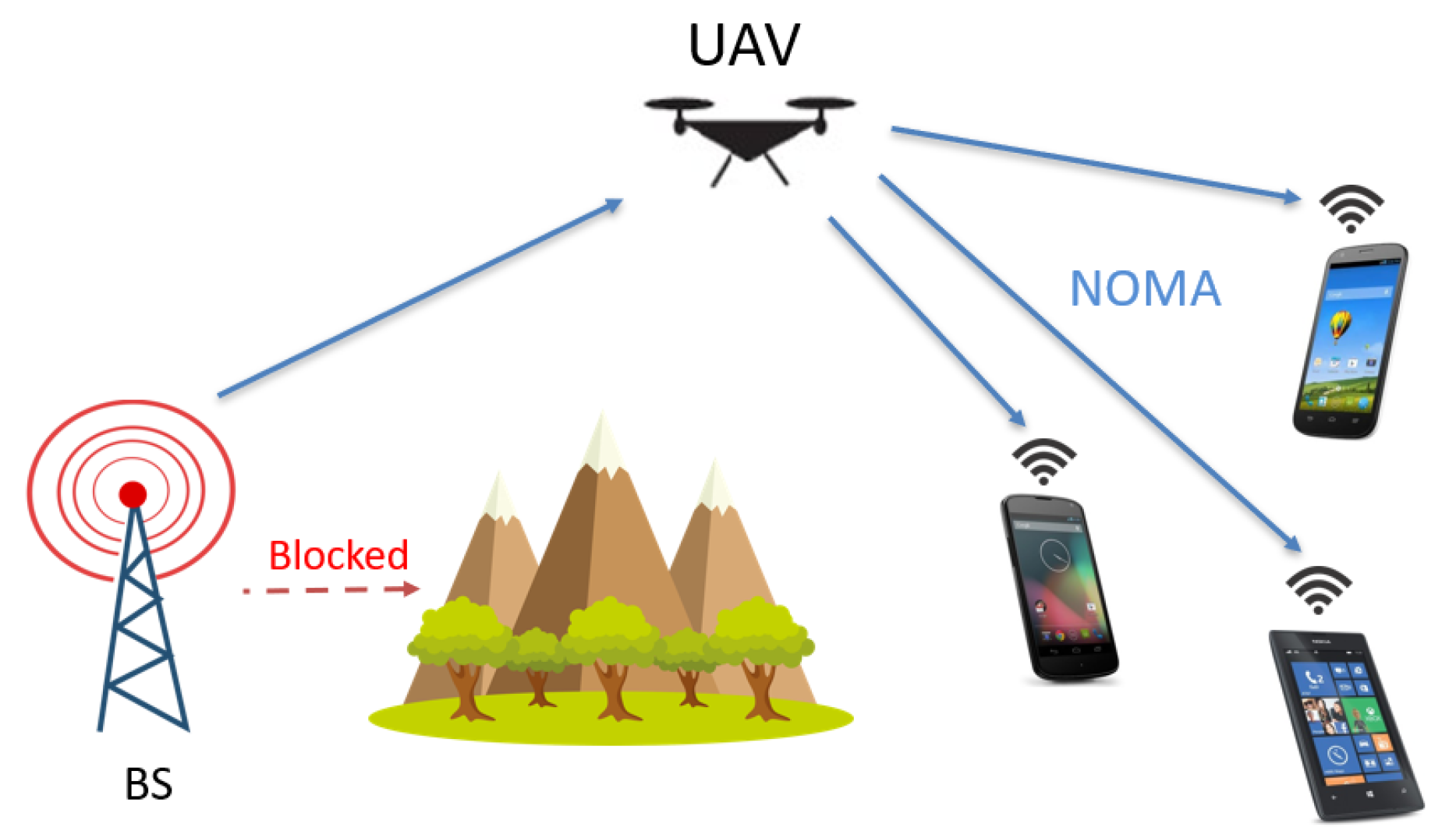
In this paper, we study a downlink system model consisting of a base station (BS), a UAV, and a set of
N GUEs, represented by
, as depicted in
Figure 1. Each of these communication terminals is equipped with a single antenna. Considering the unpredictable and complex nature of wireless communication environments, such as natural landscapes or densely populated urban areas, we make the assumption that all direct communication links from the BS to the GUEs are unavailable. Consequently, we deploy a UAV with limited cache capacity to serve the GUEs by utilizing NOMA transmissions in the FBL regime. The UAV is capable of moving on a trajectory at a fixed altitude. Throughout this research, we assume that all communication channels remain quasi-static and unchanged within a transmission frame. In other words, the parameters optimized for the current transmission frame, such as transmission power allocations at the UAV, are effective within that frame.
We denote the UAV’s cache size as , and we consider a total of C contents that can be requested by the GUEs, with the size of the c-th content designated as bits. If the requested content is available in the UAV’s cache, it is transmitted to the GUE without involving the BS. Otherwise, the UAV requests this content from the BS before the transmission from the UAV to the GUE starts.
The key parameters of the system and their notations are summarized in
Table 2, and the abbreviations are summarized in
Table 3.
2.1. FBL Transmission with Caching
In this paper, the duration of a transmission symbol is denoted as
seconds, and therefore a delay limitation of
T seconds corresponds to
symbols. To be more specific,
T seconds, or equivalently
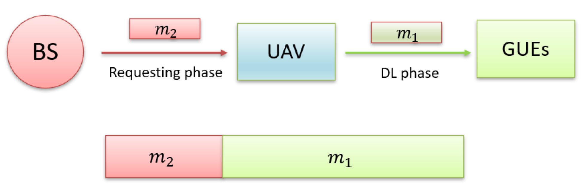
M symbol durations, set the maximum frame length for completing the requested content or task. Within a frame, two phases exist: a requesting phase spanning
symbols and a downlink (DL) transmission phase encompassing
symbols, as depicted in
Figure 2. In this study, we introduce
to indicate the request of the
n-th GUE (
implies that the
n-th GUE is requesting content
c in the
i-th frame). The size of the requested content for the
n-th GUE in the
i-th frame is
bits. It is worth noting that within each frame, each GUE is restricted to requesting only one content, e.g.,
. The UAV first checks its cache: if the requested content is cached, there is no need to consult the BS; otherwise, the content must be downloaded from the BS. After checking its cache for all requested contents in the
i-th frame, the UAV proceeds to download all the uncached but requested contents from the BS through a wireless link in the requesting phase, which spans
seconds. Subsequently, in the DL transmission phase lasting
seconds, the UAV transmits all the requested contents to the GUEs through NOMA transmissions. It is evident that the total service time for each content request is constrained by
. Following the approach in [
10], the coding rate
R in the FBL regime is approximated as
where
represents the probability of decoding error,
m is the blocklength,
stands for the SNR or SINR at the receiver,
is the inverse function of
, and
V is the channel dispersion, defined as
.
In this paper, we introduce the notation
as the caching indicator. Specifically,
signifies that content
c has been cached at the UAV during the
i-th frame. Additionally, we define
as the requesting indicator, as follows:
In particular,
indicates that content
c has been requested in the
i-th frame by one or more GUEs. Subsequently, during the
i-th frame, the size of all the requested but uncached contents is
bits. Given that the target coding rate in the request phase is
, the decoding error probability of the UAV in the
i-th frame during the requesting phase can be expressed as
Taking
as the desired achievable coding rate for the
n-th GUE in the
i-th frame, the decoding error probability during the DL phase can be formulated as follows
It is important to notice that, operating within the FBL regime, the blocklength of each frame is constrained by M, and the receiver’s decoding error probability is not negligible.
2.2. UAV Trajectory and SINR in Transmissions
In the i-th frame, the position of the UAV at the given altitude is denoted by , where is assumed to be constant in this paper, and the locations of GUEs are fixed and represented by , respectively. Therefore, the distance between the UAV and the n-th GUE in the i-th frame can be calculated by . The positions of UAV over different frames constitute the UAV trajectory in the entire considered period.
Referring to Equations (
3) and (
4), it is evident that SINR plays a substantial role in influencing the decoding error probability. Therefore, in this section, we specifically investigate the SINR under various transmission scenarios.
During the requesting phase, the UAV is receiving the required data from the BS. Given our assumption of quasi-static channels, we consider the channels to remain unchanged within a frame. As a result, the SNR for the UAV during the requesting phase in the
i-th frame is determined by the following expression:
where
represents the channel coefficient between the UAV and the BS, which varies depending on changing UAV positions. Additionally,
is the ratio of the transmission power at BS to the noise power, calculated as
, with
as the transmission power from the BS to the UAV, and
denoting the noise power of the AWGN.
During the DL phase, the UAV transmits combined signals to all GUEs based on the NOMA principle. Consequently, the signal received by each GUE in the
i-th frame can be described as follows:
where
and
stand for the message and the power allocation factor of the
k-th GUE in the
i-th frame, respectively.
represents the constraint or budget for transmission power at the UAV, and
denotes the AWGN, e.g.,
. Additionally,
is the channel coefficient between the UAV and the
n-th GUE in the
i-th frame, and this also varies depending on UAV positions. Note that
.
To implement the SIC within the NOMA technique, we initiate a reordering process for all GUEs based on their channel quality at the start of each frame. In the
i-th frame, the
N GUEs are arranged in ascending order of their corresponding channel quality, specifically,
. The GUE with the weakest channel is designated as the first GUE, while the one with the strongest channel holds the position of the last GUE. Adhering to the SIC principle, for the
n-th GUE (where
), the signals from all the previous
GUEs are decoded first. Subsequently, these decoded signals are subtracted from the superposed received signal. Consequently, the SINR for the
n-th GUE to decode its own signal in the
i-th frame can be described as follows:
In the FBL regime, it is essential to note that the SIC errors cannot be ignored. This is because the
n-th GUE must first successfully decode the signals from the preceding
GUEs before proceeding to decode its own signal. In cases where SIC fails for any GUE, the decoding process for that GUE will also be unsuccessful. Therefore, it is crucial to investigate the error rate associated with the decoding of signals from other GUEs. The SINR for the
n-th GUE in decoding the signal of the
k-th GUE (where
) in the
i-th frame can be expressed as follows:
The first GUE can directly decode its own signal by treating the signals from all other GUEs as interference, as there is no SIC being performed at GUE 1. On the other hand, the last GUE conducts a total of
SIC processes, and the calculation of its SINR becomes relatively straightforward if all the SIC processes are successful:
2.3. End-to-End Decoding Error
The primary goal of our study is to minimize the average maximum end-to-end decoding error rate for all GUEs while adhering to both coding length and maximum UAV transmission power constraints within the specified time frames. In this section, we delve into the analysis of the end-to-end decoding error probability for GUEs within a particular frame. For the n-th GUE in the i-th frame, we explore two distinct scenarios: whether the content that is being requested has already been cached at the UAV or not.
In the first scenario, where the content requested by the
n-th GUE has been cached at the UAV, the end-to-end decoding error probability
is composed of two main elements: the error probability
associated with decoding signals from other GUEs when employing SIC, and the error probability
when decoding its own signal. This is represented as follows:
Approximation (a) is applicable here because the decoding error probabilities are in the order of in the considered ultra-reliable communication scenario. Consequently, any terms involving two or more error multiplications can be safely disregarded.
We then turn our attention to the second scenario, where the end-to-end decoding error probability
for the
n-th GUE in the
i-th frame consists of three main components: the error probability
when decoding the downloaded content from the BS at the UAV, the error probability
when decoding signals from other GUEs using SIC, and the error probability
when decoding its own signal. In this scenario, we have
Approximation (b) holds here for the same reason as in approximation (a). By considering both cases, we can provide a more comprehensive description of the end-to-end decoding error rate for the
n-th GUE in the
i-th frame, denoted as
:
In Equation (
12), we can calculate
by using (
3), and
can be determined from (
4). Regarding
, it can be computed as follows:
where
can be calculated using the equation in (
8), and
is defined as
.
Note that , and will change if the position of UAV varies, which is due to the fact that all the corresponding SNR/SINRs will be different when the UAV position as well as the channel coefficient changes.
2.4. Caching Policy
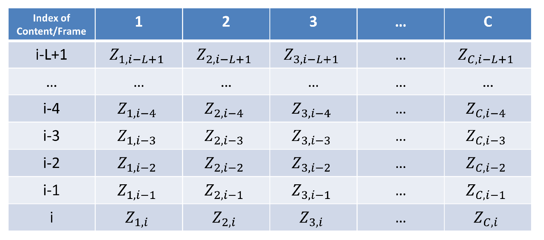
In this section, we present our UAV caching policy. Our primary objective with this caching approach is to store the most popular and frequently requested contents. To achieve this, we maintain a caching list that records all the request information from the past
L frames on the UAV. Before the start of the
-th frame, the UAV will remove the request information of the
-th frame and incorporate the request information of the
i-th frame into the caching list, as illustrated in
Figure 3. Subsequently, the UAV calculates the popularity of each content, denoted as
, which represents the popularity of content
c in the
i-th frame, and it can be calculated as follows:
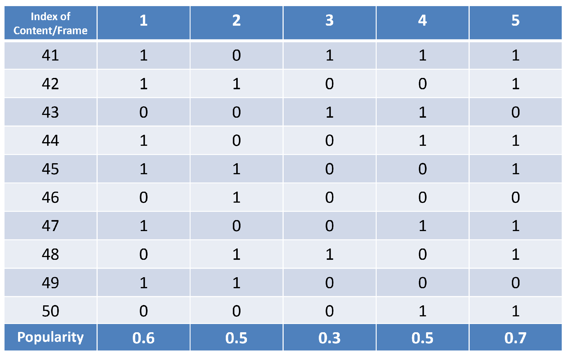
Once the popularity of all contents has been determined, the UAV proceeds to cache contents in descending order of popularity until it reaches the cache size limit
. Following this, the UAV updates the caching indicator
for use in the
-th frame. As an example,
Figure 4 provides an illustration of a caching list for
,
, and
. Assuming that all contents have the same size and the UAV’s cache can only accommodate 2 contents, by the end of the 50th frame, the UAV will cache content 1 and content 5.
3. Minimization of Maximum Error Probability
In this section, we first formulate and analyze the minimization of the average maximum error rate in the considered network and then propose a two-step alternating optimization scheme embedded within a DDPG algorithm to tackle the proposed problem.
3.1. Problem Formulation
In this paper, our objective is to minimize the average maximum end-to-end decoding error rate among all GUEs within a given period/number of frames, by jointly determining the UAV trajectory
, UAV transmission power allocation factors
, and the length of the DL phase
subject to the coding length and UAV transmission power constraints. Consequently, the global optimization problem is formulated, as follows:
where
is the set of considered frames.
In P0, the first two constraints are the UAV transmission power limitation and the maximum coding length within each frame, respectively. Solving the non-convex problem P0 directly is quite challenging due to the strongly coupled parameters and highly non-linear objective function. In order to address this, we propose a DDPG-based deep reinforcement learning method embedded with a two-step alternating optimization scheme.
3.2. Deep Deterministic Policy Gradient Reinforcement Learning
In this section, we introduce and analyze the main structure of the DDPG reinforcement learning to address the UAV trajectory design in P0. DDPG stands out as a prominent deep reinforcement learning (DRL) algorithm that combines aspects of both value-based and policy-based RL techniques. It operates within the actor–critic framework, where the actor network is responsible for selecting actions based on the current environment state, while the critic network evaluates the value of these chosen actions. Both networks are trained simultaneously using the same set of experiences gathered by the agent during its interactions with the environment.
To tackle the challenge of sample correlation in reinforcement learning, DDPG employs a replay buffer to store experiences and randomly samples from this buffer during network updates. Derived from the deterministic policy gradient theorem for Markov decision processes (MDPs) with continuous action spaces, DDPG trains the networks using a stochastic gradient descent with mini-batches and updates the target networks through a soft update mechanism. The target network and replay buffer play significant roles in enhancing stability and sample efficiency.
It is evident that the UAV positions in problem
P0 are continuous, rendering the use of the deep Q-network (DQN) algorithm infeasible, as it is designed for discrete actions. The policy gradient method is sub-optimal in the considered wireless communications, as it suffers from slow convergence. Therefore, we introduce a DDPG-based algorithm to address problem
P0 with respect to the UAV trajectory design. DDPG is an off-policy actor–critic algorithm that operates without a particular system model. It is capable of learning policies in high-dimensional, continuous action spaces [
20].
The action space, state space, and reward function of the proposed DDPG reinforcement learning agent are defined as follows:
3.2.1. Action Space
In this paper, we assume that the UAV remains at a fixed altitude, limiting its movement to the horizontal x-y plane. The action space in our proposed DDPG reinforcement learning consists of the UAV movements
, i.e.,
where
represents the current speed relative to the maximum speed, with values ranging from 0 to 1, and
serves as a steering signal that specifies the desired yaw (rotation) angle (normalized by the maximum yaw angle), ranging from −1 to 1. Note that, in this paper, we assume the maximum speed of the UAV is constrained by
and the maximum yaw angle is limited by
.
3.2.2. State Space
The state space in this DRL consists of the horizontal position of the UAV in the previous frame
, the angle between the previous direction of movement of the UAV and the x-axis
, the GUEs’ current request list
, and the caching list generated from the previous frame
, i.e.,
With any given action in the
i-th frame, the x-y position of the UAV in the
i-th frame can be computed by
Here,
is the angle between the current direction of movement of the UAV and the x-axis in the
i-th frame. In this paper, we assume
, and thereby we have
3.2.3. Reward Function
In
P0, the objective is a long time average minimization problem, and it is quite challenging to directly obtain the optimal solutions considering such a long time duration. Therefore, in this paper, we equivalently minimize the maximum end-to-end decoding error probability during each frame. Consequently, we construct the reward function with the objective to minimize the maximum end-to-end decoding error rate among all GUEs in any given frame
i, i.e.,
where
and
V are constants to balance the reward.
is obtained when the embedded two-step alternating optimization subroutine is completed with the given UAV position
, which is provided by the updated state space.
Based on the above definitions, we propose a DRL-based algorithm according to the DDPG algorithm described in [
20]. In this section, we aim to solve
P0 without considering the optimization of UAV transmission power allocations
and the length of the DL phase
, which will be addressed via an embedded two-step optimization subroutine introduced later. Such a proposed DDPG-based algorithm can be deployed at the BS which can collect all the required information about the channel states and apply the policy to all served GUEs and UAV.
The primary distinction between traditional DDPG and our proposed algorithm in this paper lies in the integration of the optimization subroutine aiming to optimize UAV transmission power allocation factors and the length of the DL phase .
The DDPG reinforcement learning comprises two essential components within the learning agent: (a) an actor network, responsible for determining the action based on the current state, and (b) a critic network, tasked with assessing the action chosen using the reward feedback from the environment. These networks are represented as and , with neural network weights denoted as and , respectively. The DDPG reinforcement learning algorithm includes three sequential steps.
The initial step involves gathering experience through interactions within the environment. Using the current network state , the actor network produces actions related to the UAV movement. The embedded two-step optimization subroutine determines UAV transmission power allocation factors and the length of the DL phase . Subsequently, this joint action is executed at the UAV. The corresponding reward and the subsequent state are observed from the environment. The transition of the state information, represented as , is stored within the experience replay memory to facilitate the training of both the actor and critic networks.
The next step involves the training of the actor and critic networks using the accumulated experience. To prevent potential issues of divergence stemming from deep neural networks (DNNs), a random minibatch of transitions is extracted from the experience replay memory, breaking the correlation between experiences. The training of the critic network focuses on minimizing the loss function
where
denotes the size of minibatch, and
where
is the discount factor,
denotes the actor target network with weight
, and
is the critic target network with weight
. Subsequently, the actor network is trained according to the policy gradient
The final step is the update of target networks. To maintain the stability of network training, the actor and critic target networks are updated softly:
where
represents the update ratio of the target network.
3.3. Two-Step Alternating Optimization
In the previous subsection, we have introduced a DDPG method to tackle the problem of UAV trajectory designs in
P0. When the UAV trajectory is given, i.e., its location in each frame is known, we can transform
P0 into following problem
P1:
Solving P1 in the i-th frame enables us to jointly optimize the transmission power allocation factors for GUEs and the length of the DL phase with the objective aiming to minimize the maximum end-to-end decoding error rate among all GUEs while adhering to the coding length and UAV transmission power constraints.
In this subsection, we propose a two-step alternating optimization subroutine to demonstrate how to attain the optimal UAV transmission power allocation factors and the optimal length of the DL phase when the UAV position is fixed in the i-th frame. Note that such a UAV position is obtained from the state space updated by the action chosen in the DDPG structure.
In the j-th optimization iteration within the i-th frame, we initially set to the value from the previous iteration, denoted as , which relies on the optimization results from the previous -th iteration, to decouple the optimization variables. Then, we determine the UAV transmission power allocation factors . After that, with the predetermined , we find the optimal value of in the next step. Consequently, the obtained and are utilized in the -th iteration.
3.3.1. Optimization of UAV Transmission Power Allocation Factors
During the
j-th iteration, when we keep
as a constant, it is evident that
is also unchanging. Consequently, our current goal is to attain the best power allocation factors
at the UAV that minimize the maximum end-to-end decoding error rate among all GUEs. As a result,
P1 transforms into
P2 under the fixed value of
:
where
represents the power allocation factors at the UAV, and
is the end-to-end decoding error probability of the
n-th GUE in the
j-th optimization iteration within the
i-th frame.
P2 remains a challenging min-max optimization problem. To tackle this, we further break down
P2 into
N sub-problems, and considering the
n-th GUE, we construct:
We formulate a sub-problem P2A for each GUE . In P2A, we focus on minimizing the end-to-end decoding error probability only for a single GUE. ensures that this minimized error probability is the maximum among all GUEs, making the attained power allocation factors a potential solution for P2. To obtain the solution for P2 from P2A, we introduce Lemma 1.
Lemma 1. Among all the sub-problems P2A, the one that attains the minimum value in the objective function shares the same solution with P2.
Proof. Assume that the t-th sub-problem is the one that attains the minimum value of the objective function, meaning for all GUEs , and then when we apply the solution obtained from the t-th sub-problem to P2, the objective function’s value must remain the same as .
If the solution of P2 differs from the solution of the t-th sub-problem, denoting as the minimum end-to-end decoding error probability based on the solution of P2, we would naturally expect that because P2 is a minimization problem. This implies that the solution leading to in P2 must be the solution of the u-th sub-problem. However, it contradicts our initial assumption that , since should be satisfied. Thus, the solution of P2 must be the same as that of the t-th sub-problem, which achieves the minimum value of the objective function among all the N sub-problems. □
When we aggregate the solutions obtained from all the N sub-problems, according to Lemma 1, we can confidently claim that the sub-problem solution that yields the lowest end-to-end decoding error probability in the objective function is the solution of P2.
Every sub-problem
P2A can be addressed using a nonlinear optimization tool. However, it is worth noting that the
Q function significantly escalates the computational complexity. To mitigate this challenge, following the approach in [
21], we can approximate the
Q function with the
F function for any fixed
m and
D. For example,
can be approximated as
:
where
,
,
and
.
Via (
29), when
m and
D are fixed, the total end-to-end decoding error probability for the
n-th GUE in the
i-th frame is represented as
:
We can subsequently convert
P2A into following
P2B:
where
represents the value of
in the
j-th optimization iteration during the
i-th frame. We can then solve
P2B by using a nonlinear optimization tool without the inclusion of the
Q function, resulting in a reduced computational complexity while sacrificing accuracy due to the approximation. The choice between solving
P2A or
P2B should be made considering the trade-off between solution accuracy and computational complexity.
By solving either P2A or P2B, we can determine the optimal power allocation factors on the UAV. These obtained in the j-th optimization iteration during the i-th frame are represented as .
3.3.2. Optimization of the Length of DL Phase
During the second step of the two-step alternating optimization subroutine, we keep the power allocation factors on the UAV fixed as
, and this transforms
P1 into
P3 for determining the optimal duration of the DL phase in the
j-th iteration during the
i-th frame.
where
and
represent the duration of the DL phase and requesting phase in the
j-th optimization iteration during the
i-th frame, respectively.
P3 is a discrete optimization problem, and when M is large, using exhaustive search becomes inefficient. To address this, we can initially treat as a continuous variable and solve P3 without considering the integer limitation by using a nonlinear optimization tool. Similarly, as in P2, we can employ a similar approach to decompose P3 into several minimization sub-problems. After completing the two-step alternating optimization subroutine, the optimal is determined by rounding the continuous solution to the nearest integer.
By iteratively solving P2A/P2B and P3, we can obtain the solution of P1 once they converge. Algorithm 1 below outlines the details of the proposed two-step alternating optimization subroutine.
| Algorithm 1 Two-step alternating optimization subroutine |
| Initialization: |
- 1.
Initialize , .
|
| Actions: |
- 1.
For - 2.
Obtain by solving P2A/P2B with . - 3.
Obtain by solving P3 with . - 4.
End If converged.
|
Note that in the last iteration, we must perform action 2 one more time to acquire the final power allocation factors on the UAV during the i-th frame.
3.4. Joint Trajectory Design and Resource Optimization Framework in the UAV-Assisted Network
In this section, we will explicitly illustrate the comprehensive framework in the considered UAV-assisted downlink network. The specific details can be found in Algorithm 2, presented below.
| Algorithm 2 Framework in the UAV-assisted Network |
| Initialization: |
- 1.
Initialize caching size limitation at the UAV, total length of a frame M, transmission power from the BS to the UAV during the requesting phase, and maximum available transmission power at the UAV during the DL phase. - 2.
Initialize all neural networks and the experience replay memory.
|
| Actions: |
- 1.
Obtain initial state . - 2.
For - 3.
Check all the content requests from the GUEs with the cached contents at the UAV, and generate , and . - 4.
Determine the sampling rate selection and UAV movement action by the actor network according to current state ; - 5.
Obtain the location of UAV , which is given by the updated state space, and calculate the channel coefficients and . - 6.
Reorder the GUEs into an increasing order, i.e., . - 7.
With given and , obtain the transmission power allocation factors at the UAV, and the length of the DL phase in the i-th frame via Algorithm 1. - 8.
Observe reward and new state . Update the caching list at the UAV, calculate the popularity of each content , and then update the cache. - 9.
Store transition in the experience replay memory; - 10.
Sample a random minibatch transition from the experience replay memory; - 11.
Train the critic and actor network, respectively; - 12.
Update target networks. - 13.
End for.
|
3.5. Convergence and Complexity Analysis
3.5.1. Convergence
In our proposed approach, we conduct training on the actor network and critic network using a gradient descent with exponentially decayed learning rates. Consequently, the weights and will reach convergence after a finite number of iterations, ensuring the overall convergence of the proposed algorithm. Although it is challenging to theoretically analyze the time required for the convergence prior to network training, we rely on simulations to demonstrate the convergence of our proposed algorithm, as indicated in the numerical results.
For the embedded two-step alternating optimization subroutine, we introduce the Lemma 2 below to analyze its convergence.
Lemma 2. Algorithm 1 converges when the optimized objectives in P2 and P3 have the same value.
Proof. Assume that the optimized objectives in P2 and P3 are and , respectively. If , then we have , since the worst case in solving P3 after P2 is achieved by keeping to be the same as what was fixed in P2. This indicates that any improvement (i.e., reduction) in implies that we should have . Consequently, if , there must be an improvement in the optimized objective, and hence Algorithm 1 will continue until . Therefore, Algorithm 1 will stop/converge when the optimized objectives in P2 and P3 have the same value. □
Furthermore, since both P2 and P3 are minimization problems, and there exists a lower bound on the total decoding error rate, together with the characterization in Lemma 2, the convergence of the embedded two-step alternating optimization subroutine is ensured.
3.5.2. Complexity
In our proposed algorithm, the well-trained actor network generates actions for the UAV during each frame. In our study, the computational complexity for the action generation for UAVs is expressed as , where is the number of network layers, and represents the number of neurons in the l-th layer. Therefore, the total complexity of the DDPG algorithm is .
In the embedded two-step alternating optimization subroutine, P2 and P3 are solved iteratively based on Lemma 1. P2B involves N variables. Consequently, the necessary number of iterations is , where represents the desired accuracy of the interior-point method in solving P2B. Additionally, P2B encompasses at most constraints, and hence the computational complexity for solving P2B is , which is equivalent to . Therefore, during one iteration in Algorithm 1, the computational complexity for solving P2 is , since we have N sub-problems. For each sub-problem of P3, we have one variable and one constraint when we relax , and hence the computational complexity for solving P3 is during one iteration in Algorithm 1. Assuming that we have iterations (the worst case) in Algorithm 1, the computational complexity is , which is equivalent to .
Finally, the overall computational complexity of Algorithm 2 is
4. Numerical Results
In this section, we present the numerical analysis of the minimized average maximum end-to-end decoding error probability among all GUEs by using the proposed algorithm. In our numerical results, we represent the end-to-end decoding error probability on a logarithmic scale. We first show the average min-max end-to-end decoding error rate versus the maximum block length constraint under different UAV transmission power constraints as well as different UAV trajectories. Additionally, we explore the influence of cache size limitations and the length of the caching list at the UAV. Furthermore, we display the UAV trajectory optimized through the proposed two-step alternating optimization scheme embedded within the DDPG algorithm. Finally, we provide insights into the convergence performance of our proposed learning structure.
In the simulations, the channels are modeled as follows: For GUE
n in the set
, the channel is generated using the formula
, where
represents the distance between the UAV and the
n-th GUE,
is the path loss exponent, and
is the complex Gaussian distributed fading component for the
n-th UE. In a similar manner, the channel between the BS and the UAV is characterized by
, where
denotes the distance from the BS to the UAV,
is the path loss exponent for that link, and
represents the complex Gaussian distributed fading component associated with the BS-UAV connection. Unless stated otherwise, the UAV serves 3 GUEs in the considered network. The simulation parameters are listed in
Table 4, below.
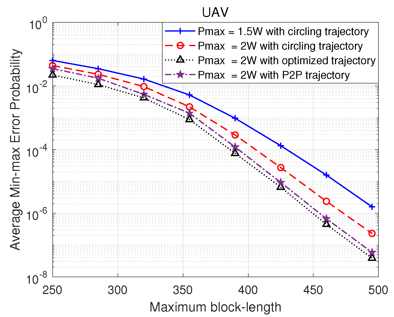
In
Figure 5, we analyze the average min-max error probability attained with the proposed algorithm considering three different UAV trajectories. In this figure, the curves in red and blue denote for the average min-max error rates under different UAV transmission power budgets
, when the UAV is following a circular trajectory, while the dotted curve in black represents the average min-max error rate when the UAV has the optimal trajectory with
, and the dash dotted curve in purple denotes the average min-max error probability when the UAV has a point-to-point (P2P) trajectory with
. Such a P2P trajactory starts at (0, 380) and ends at (350, 100) with a straight line in the considered 400 m × 400 m square area. It is evident that UAV using the optimized trajectory, which is obtained from our proposed DDPG algorithm embedded with the two-step alternating optimization subroutine, results in the smallest average min-max error rate. We further observe that the min-max error probability is reduced when the blocklength constraint
M increases, which is expected since increasing
M is the same as extending the transmission time, resulting in less strict requirements on the coding rate. We further observe that enlarging the transmission power budget
at the UAV improves the performance as well. By increasing
, we can obtain a higher SNR/SINR and hence improve the min-max error probability.
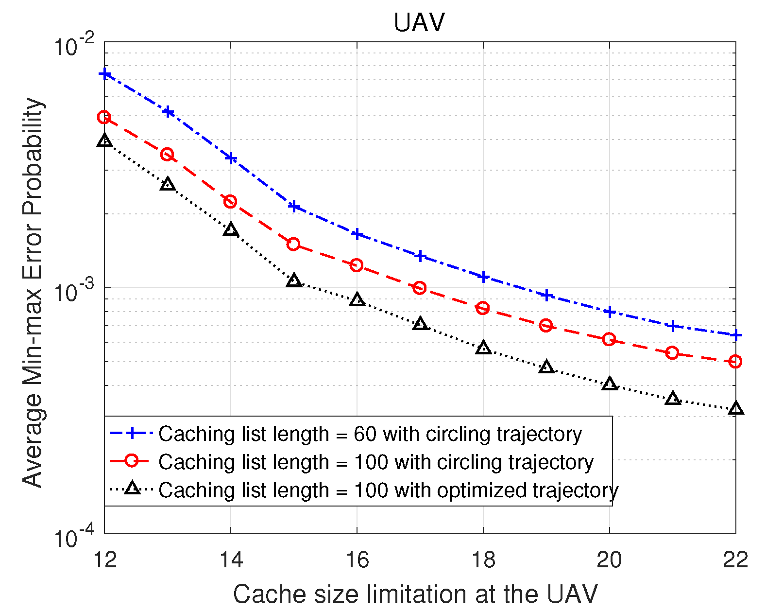
Next, we investigate the impact of the cache size limitation and the length of the caching list in
Figure 6. This figure demonstrates the curves of the average min-max error probability versus the UAV’s cache size limitation
, where the red and blue curves represent the average min-max error rates for different lengths
L of the caching list when the UAV follows a circling trajectory, and the dotted black line illustrates the average min-max error rate when the UAV adopts the optimal trajectory with
. In
Figure 6, it is readily observed that the performance with a larger caching list is consistently better than the one with a smaller caching list. This is due to the fact that a larger caching list increases the probability of caching all the popular contents, making the caching procedure more efficient. We additionally observe that a larger cache size results in a lower average min-max error rate. This is attributed to the improved caching capability at the UAV, allowing more contents to be served without consulting the BS and leading to an improved average min-max error probability. However, it is important to note that the improvement becomes smaller as the cache size is increased. This phenomenon occurs because the most popular content is the first to be cached, and further increasing the cache size mainly enables the UAV to store less popular contents, providing limited improvements in the min-max error rate. Last but not least, even when all contents are cached at the UAV, decoding errors may still occur during the DL phase. Consequently, the min-max end-to-end decoding error probability does not vanish by merely increasing the UAV’s cache size.
Furthermore, considering both the UAV trajectory design, transmission power allocations, and determination of the duration of the DL phase, we illustrate the optimal UAV trajectory in
Figure 7. In the figure, the GUEs are randomly distributed within a circle whose center is located at (350, 100). The initial position of UAV is set to be (0, 380) and the BS is located at (350, 380). We can observe that the UAV will first fly somewhat towards the BS, since at that stage the error rate arising from the UAV downloading in the requesting phase has more impact on the end-to-end error probability. Afterwards, the UAV flies more towards the GUE cluster, since, at that stage, the decoding error rate in the DL phase dominates the overall error probability. We also observe that the UAV will continue hovering in a very small range close to the GUE cluster, which is due to the fact that such a position is the optimal location with which the overall end-to-end error rate is minimized. It is worth noting that when we alter the location of the GUE cluster, the UAV trajectory changes correspondingly.
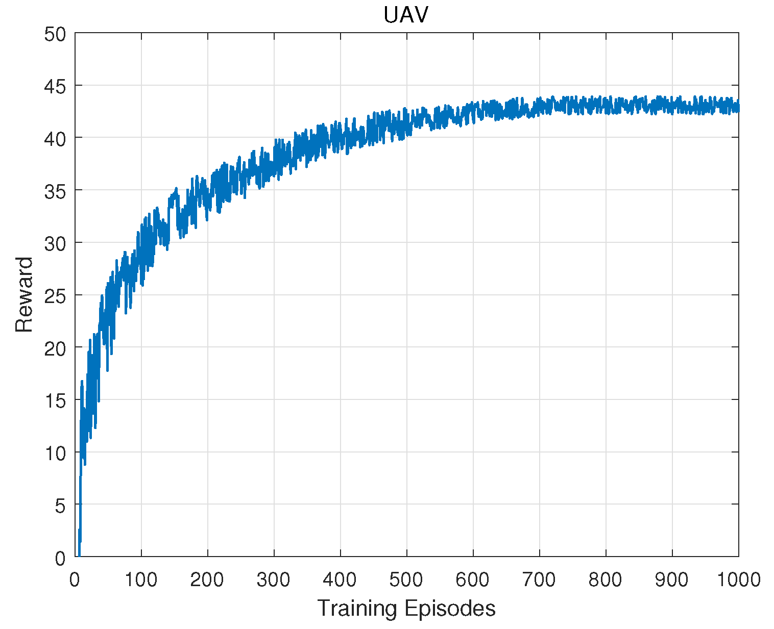
Additionally, we evaluate the convergence of the proposed DDPG algorithm embedded with the two-step alternating optimization subroutine, as presented in
Figure 8. This figure shows the reward curve as the number of training episodes grows. In
Figure 8, the results reveal that the UAV trajectory training will converge around 710 episodes, which assures the feasibility of our proposed algorithm in addressing the global optimization problem.
In
Figure 9, we validate the effectiveness of hybrid frequency-division multiple access (FDMA)-NOMA to overcome the interference bottleneck as the number of GUEs grows. In the hybrid FDMA-NOMA, we first divide all the GUEs into different groups, and then FDMA is utilized between different groups and the GUEs in the same group receive data from the UAV via NOMA transmissions. To perform the hybrid FDMA-NOMA, we can simply execute step (6) for every group independently in Algorithm 2 and the rest of the steps remains the same. In
Figure 9, we explicitly demonstrate the average min-max error probability under different grouping scenarios considering 4 and 6 GUEs. We observe that with the increasing number of GUEs, the average min-max error probability increases. We further notice that for the same number of GUEs, the more groups we have, the smaller average min-max error probability we can achieve. This is mainly due to the fact that with less GUEs in one NOMA group, the GUEs experience less impact from the SIC errors.
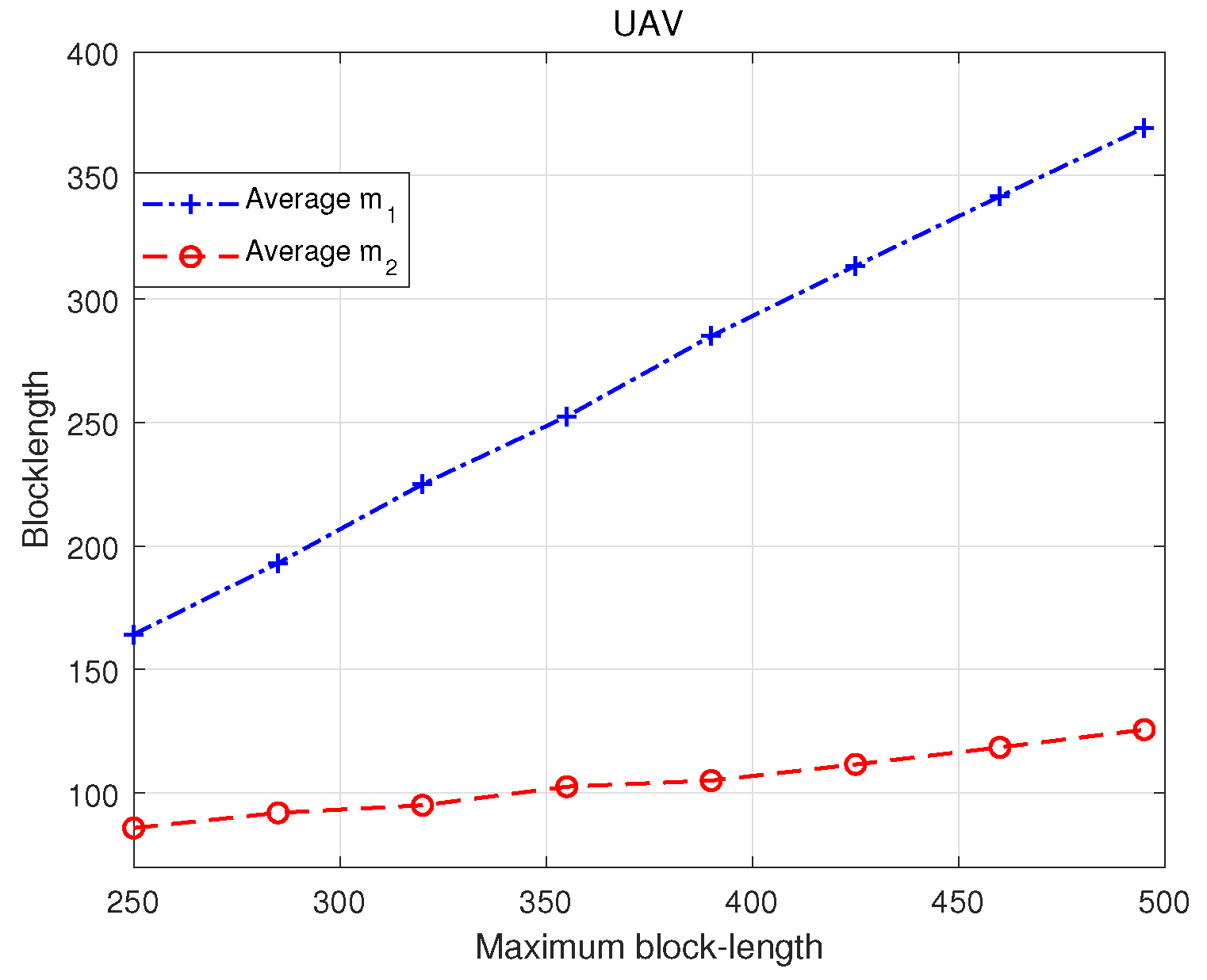
Finally, we plot
Figure 10 to illustrate the optimized values of
and
, as the maximum blocklength
M keeps increasing. In order to focus on
and
, we keep the UAV hovering within a small range of the final position obtained by the optimized UAV trajectory, as shown in
Figure 7. In
Figure 10, we continuously increase the maximum blocklength
to plot the average
and
. We observe that with the increase in
M, more time is allocated to the DL phase, resulting in a relatively fast growth in
. Compared with
,
increases slowly. This can be attributed to the fact that during the DL phase, the UAV performs downlink NOMA transmissions to the GUEs, and allocating more time to such a phase mitigates the impacts from both the self-decoding error and SIC errors. Hence, the optimized allocation indicates that we benefit more from increasing
rather than
, especially in later stages of the UAV flight, at which time most popular content is highly likely to be already stored at the UAV and communication with the BS has a lower priority.


