1. Introduction
Unmanned aerial vehicles, which are deployed in various civil settings in urban regions, have made significant contributions to the development of smart cities [
1,
2,
3]. Based on their functions and structures, UAVs can be divided into two categories: fixed-wing UAVs and helicopters [
4,
5,
6]. Fixed-wing UAVs have the advantages of fast flight speed, extended range, high efficiency, and low noise [
7,
8]. However, the application of fixed-wing UAVs is restricted by the high landing site requirements associated with their takeoff and landing manner. To a certain extent, the development of helicopters compensates for this shortcoming. The main rotor of a helicopter serves as both a lifting surface and a maneuvering surface, thus enabling the helicopter to hover at a fixed point and take off and land vertically [
9]. Nevertheless, this method for generating lift in helicopters has drawbacks, which include significant nonlinear rotor dynamics, sluggish flight speed, a constrained range, and low aerodynamic efficiency, particularly for the asymmetry of the rotor airflow during forward flight [
10,
11]. The compressibility of the forward rotor blades and the airflow separation of the rear rotor blades restrict the maximum forward speed of helicopters, and the maximum cruise speed of a conventional helicopter is generally approximately 300 km/h [
12]. Speed is frequently a major constraint for helicopter applications [
13]. Many UAV researchers have long been in tireless pursuit of a solution to efficiently combine the benefits of both types of aircraft and, thus, construct a UAV that can both cruise at high speed and take off and land vertically in response to the increasingly complex working environment of aircraft [
14]. Tilt-rotor VTOL UAVs, which combine the benefits of helicopters and fixed-wing UAVs, are currently being deployed for more missions and have a promising application [
15,
16,
17,
18].
The tilt-rotor UAV is a novel type of UAV that can hover at a low speed and cruise at a high speed [
19]. The combination of the advantages of both helicopters and fixed-wing UAVs has lent the tilt-rotor UAV great research significance in the field of aircraft research [
20]. A tilt-rotor VTOL UAV has three flight modes—the helicopter mode, fixed-wing mode, and transition mode [
21]. In the transition flight phase, UAVs are characterized by actuator redundancy, strong nonlinearity, cross-coupling, and multiple flight modes [
22]. Acceptable power distribution and a feasible range of speed are necessary to ensure that the lift of the UAV satisfies the flight needs and that the flying attitude continues to change during the process. Consequently, the transition flight mode is somewhat complicated for VTOL UAVs [
23,
24,
25]. The transition flight corridor of the UAV must be determined to allow the aircraft to fly securely and ensure the safety of the transition flight. Choi et al. [
26] estimated the transition corridor of a tilt-rotor VTOL UAV using leaf element theory and momentum theory, with a scaled-down sample serving as the study object. Moreover, the findings of the experimental tests were compared in terms of the nacelle tilt angle and the flight speed envelope. After multiple flight tests, the UAVs were able to transition from hovering mode to cruising mode. With a tilt-rotor aircraft as the research object, Cao et al. [
27] proposed a tilt angle-speed envelope for the transition process. In order to calculate the tilt angle–velocity envelope for wing stall limitations, envelope analysis was performed at both low and high speeds. Zhou et al. [
28] established a mathematical model of a composite coaxial helicopter. They thoroughly fine-tuned the states and control variables at different airspeeds using Newton’s iterative method and provided a basic method to calculate the transition corridor using a small coaxial fixed-wing helicopter as an example.
The works mentioned above focus primarily on the calculation of transition corridors for tilt-rotor VTOL UAVs, while there is little research on transition strategies. In order to ensure the safety and smoothness of aircraft transition during the transition process, the transition strategy should be established according to the transition corridor. In recent years, Zhang et al. [
29] proposed a method to deal with the transition problem by using different transition strategies. In order to reduce the interference caused by the wings, their UAVs underwent a 90-degree yaw deflection prior to the changeover phase before resuming their original position. The transition structure of a twin rotor tail-sitter UAV was discovered by Forshaw et al. [
30], who also presented the results of a simulation using a linear transition strategy. Banzadeh and Taymourtash [
31] employed cross-coupled and thrust-vectoring control to produce the best transition trajectory for the trail-sitter UAV. In order to ensure that the computed trajectory was realistic, the researchers added physical constraints to the optimization process. Additionally, they considered the effect of thrust-to-weight on the transition phase. In order to optimize the reverse transition, Verling et al. [
32] used a self-designed cost function (SDFC). After optimization, they reported only one observation of reverse transition with minimal variations in height. However, the improved transition exhibited a decrease in height and an increase in horizontal displacement.
Although there has been excellent research conducted using linear or optimum transition approaches, none of these have yielded satisfactory results. As a result, the primary contributions of the present study can be summed up as follows:
- 1.
By using the transition strategy proposed in this paper, the connection between transition time and attitude stability can be balanced more effectively and quickly than the linear transition method used by Forshaw et al. [
30] and Jung et al. [
33]. The approach discussed in this study may produce a tilting trajectory with improved transition quality, which saves a considerable amount of time for parameter adjustment and eases the difficulty of trajectory design. Moreover, the tilting trajectory is constantly contained by the transition corridor’s secure boundary;
- 2.
The final value and the constraint process are determined based on the flying characteristics of the transition process and the actual physical constraints in this study, and the optimal approach with constraints is used to address the issue. In contrast to the previous research of Oosedo et al. [
34] and Oosedo et al. [
35], this study proposes a transition strategy that obtains the optimal solution by solving the nonlinear programming problem. A tilting trajectory that meets the optimization criteria of low attitude, minimal control input, and shortest transition time can be obtained by designing the objective function and constraining the state variables;
- 3.
Performance indexes are established according to the requirements of transition quality with respect to transition time, attitude stability, and control continuity. After that, sensitivity analysis is performed based on the various index items with various dimensions and effects. When compared to the work of Kita et al. [
36] and Naldi et al. [
37], the research described in this study considers various design factors, and the parameter variations during the transition process are discussed in detail.
The rest of the paper is organized as follows.
Section 2 establishes the dynamics model of the studied tilt-rotor VTOL UAV and then introduces the typical modalities of the UAV and maneuvering logic in various modalities. The transition corridor is calculated in
Section 3, and an appropriate transition strategy is created.
Section 4 presents and discusses the simulation results, and
Section 5 concludes.
3. Research on Multi-Mode Flight Transition Strategies
The trajectory design, which the transition mode control law design is based on, represents the first step in the study of the transition mode control strategy. With the continuous change in the tilting angle during the transition phase, the speed and aerodynamic characteristics of the UAV change continuously. Thrust and lift must work in conjunction to overcome gravity and drag during flight so that the transition process continues smoothly. However, due to various constraints, the tilting process of the UAV can only be completed within a specific speed range, which forms a unique transition corridor for tilt-rotor VTOL UAVs. Therefore, the transition corridor is a prerequisite for designing the trajectory, and the transition strategy is the key to achieving modal conversion during the transition process of tilt-rotor VTOL UAVs. How to design an appropriate transition strategy so that the tilt-rotor VTOL UAV switches smoothly and safely while maintaining the altitude and the stability of the attitude is an important problem regarding the control of the tilt-rotor VTOL UAV in the transition phase.
3.1. Calculation of the Transition Corridor
In helicopter mode, the gravity of the UAV is fully balanced by the thrust generated by the propellers, and this leads to the low-speed lift characteristic boundary of the transition corridor. With the decrease in the tilting angle, the gravity of the UAV gradually transitions from being balanced by the propellers to being balanced by the wing. In this process, if the tilt occurs very quickly, the rotor thrust also decreases very quickly, as a result of which the speed of the UAV fails to build up, and the wings are unable to provide enough lift, which puts the UAV at risk of stalling. Currently, the required lift is less than the available lift, and the required angle of attack for the wing is now larger than the stall angle of attack. The UAV is outside the left and lower boundaries of the transition corridor, a fact that cannot ensure normal and safe flight.
Since the tilting power cannot compensate for the rise in drag generated by the UAV, the only way to minimize the drag with the increase in speed is to alter the angle of attack of the UAV. Assuming that the angle of attack is always within a small range and the UAV is always in level flight, regardless of the lateral influence, the angle of attack can be considered as the pitch angle, which is why adjusting the angle of attack is equivalent to adjusting the pitch angle. When the angle of attack (pitch angle) is less than the zero lift angle, the wing produces negative lift, suggesting that the direction of lift is negative and points downward to the wing. At this point, the wing transforms into a load, creating a highly dangerous flight condition. Therefore, it is essential to constrain the lower limit of the angle of attack of the tilt-rotor VTOL UAV with the increase in speed, which also constitutes the upper boundary of the transition corridor. The maximum forward flying speed of the tilt-rotor VTOL UAV during the transition process is constrained by the rotor’s available power, and the right boundary of the transition corridor can be identified based on the rotor’s maximum power limit. When the tilt-rotor VTOL UAV tilts rapidly, it must additionally balance the horizontal component of the thrust produced by the propellers with the drag, and the vertical lift generated by the wing and the thrust generated by the propeller are balanced with gravity.
In this study, the transition corridor problem is transformed into a conventional nonlinear optimization problem in order to solve it quickly. The maximum and minimum speeds are calculated, and these values satisfy the constraint conditions at various tilting angles, using speed as an optimization indication.
The next step involves selecting the state variables. With regard to the transition process of the tilt-rotor VTOL UAV studied in this work, in addition to the tilting angle, the variables that generally affect the transition flight are flight speed, angle of attack (simplified as pitch angle), front power throttle, rear power throttle, and elevator deflection. Therefore, the above-mentioned variables are selected as state variables. For calculation purposes, dynamic pressure is used instead of speed, which is then transformed by calculating the optimization objective function. The transformation equation is as follows:
Finally, the dynamic equation constraints are introduced. As the longitudinal characteristics of the UAV are mostly affected during the tilting transition process, the dynamic equations are trimmed to obtain the trim relationship and state variable constraints based on lifting balance, available power constraints, and torque balance:
where
,
, and
represent the aerodynamic drag, lift, and moment coefficients, respectively;
denotes the position of the rotor in the body-fixed frame. The subscript
represents the projection of the distance from the front propeller to the center of gravity into the
x-axis, while
represents the projection of the distance from the rear propeller to the center of gravity into the
x-axis;
is the dynamic pressure;
is the tilting angle of the rotor;
is the elevator deflection;
is the thrust generated by the front propeller; and
represents the thrust generated by the rear propeller. The aerodynamic coefficients can be calculated based on the modeling equation, and the influencing factors of the equation mainly include the angle of attack
and the forward flight speed
V, which can be assigned from the previous round of results at each iteration. While the first equation of the constraint condition suggests that the propeller thrust must be limited by the maximum available power, the second equation shows the balance between propeller thrust, lift, and gravity, thus maintaining horizontal-level flight. The third equation shows that the pitch moment suffered by the UAV is 0, while the remaining expressions are constraints for each state variable.
3.2. Optimal Design of Transition Strategies
A tilting transition corridor is essentially the set of all feasible paths, and a feasible path is a connection of feasible state points in a specific tilting mode. In order to ensure the rapidity and smoothness of the transition process, it is necessary to choose an appropriate transition trajectory within the transition corridor. Based on a specific evaluation criterion, a set of optimal tilting points can be selected to identify an optimal tilting path under this evaluation criterion.
The following is an expression of the longitudinal dynamic equation of the UAV in the body-fixed frame:
where
u and
w are the velocity components pointing to
and
, respectively, under the body-fixed frame.
In order to be able to control the tilting angle rate and ensure that the tilting angle acceleration is within the constraint range, the tilting angle
and the tilting angle rate
are also written in the form of state equations and solved as state variables, while the tilting angle acceleration
is used as the control variable.
The limitations of the state and control variables are discussed next. Assuming that the initial state of the transition process is hovering, i.e., when switching from helicopter mode to fixed-wing mode, the starting values of the state and control variables are set as follows.
where
and
are the normalized forward and backward propeller thrust coefficients, respectively.
At the end of the transition process, the flight state is considered to be level flight, and the state and control variables are within a specific range of values. At this point, the tilting angle is
, and the speed can be obtained based on the left and right boundaries of the tilting transition corridor.
The flight state is required to adhere to the standards of stability and safety during the entire flight process. The state variables are constrained, while the control variables are restricted by the physical deflection limit. The constraint conditions are as follows:
The transition strategy proposed in this paper is based on a tilt-rotor aircraft configuration that can cruise at high speeds, which will be used in the control of its transition process in the future.
As the evaluation criteria in this section are the minimum maneuver and the shortest time, the selected performance indicator
is shown below:
where
is the initial time;
is the final time;
c is the weight of
t,
t is the difference between the terminal time
and the initial time
, that is
, and
a and
b are the weights of each control variable. If we want to satisfy the evaluation criteria, the selected performance indicator
has to be as small as possible. When switching from fixed-wing mode to helicopter mode, i.e., in reverse, the constraint range remains unchanged, but the constraint range of the pitch angle is appropriately relaxed.
3.3. Gaussian Pseudospectral Method
The transition strategy employed in this paper is fundamentally a trajectory design problem, which is often transformed into an optimal control problem for which the Gaussian pseudo-spectral method is used to solve. In the aforementioned section, the longitudinal dynamics of the tilt-rotor VTOL UAV are modeled, the initial and final conditions of the transition process are summarized, the state and control variable constraints of the transition process are summarized, and the performance metrics are given.
The transition strategy design problem of the tilt-rotor VTOL UAV studied in this paper can be transformed into a Bolza-type optimal control problem, described as follows:
where
represents the steady-state indicator and
represents the process indicator. The optimization problem of the transition strategy is equivalent to solving the optimal control variables
that satisfy the constraints of the state and control variables and minimize the performance indicator
.
The following condition is satisfied with Equation (
17):
Firstly, the time-domain transformation is performed as below:
Then, the original time domain
is mapped into the normalized interval
. Equations (
16) and (
17) can be rewritten as
Subsequently, the state and control variables are approximated using Lagrange polynomials of the order
and
N, respectively.
where the discrete-time point
is the collocation point of the interpolating polynomial, and
denotes the basis of the Lagrange polynomial.
The discrete approximation of the performance indicators is as follows:
where
The state equation can be discretized and approximated as follows:
where the derivative of the Lagrange polynomial at the collocation point can be expressed as
By introducing the above differential matrix, the state equation constraints are transformed into algebraic constraints:
The state equation constraint is calculated at the coordination point. The relationship between the initial and final values of the state variables can be obtained by adding up the values of each trimming point:
In summary, the continuous optimal control problem of tilt-rotor VTOL UAV is transformed into a discrete Nonlinear programming problem. The performance index is minimized by identifying the ideal control sequence that satisfies the discrete state equations and constraints at each coordination point.
3.4. Sensitivity Analysis of Optimization Indicators
In the present study, the tilting trajectory optimization issue is reformulated as a nonlinear, optimal problem with state constraints and control constraints. Establishing a performance indicator function to assess the quality of this transition process and the effectiveness of control is a key step in optimal control design. Therefore, in this paper, the primary solution to the optimization problem lies in designing the optimization indicator for the whole transition process. Since the problem studied in this paper is a typical multi-objective optimization problem, the dimensions and effects of these variables differ, which is why the sensitivity analysis and weight design of each influencing factor cannot be ignored when constructing the objective function.
The performance indicators can generally be expressed as follows:
where the system is driven by
from time
till time
, and
is the state curve of the entire process.
The first term in the performance indicator, known as the “end-valued performance indicator”, signifies the distance between the final value of the system and the design target set, reflecting the accuracy of the final convergence of the system to the target state. The integral term, which is a component equation containing state variables and control variables in the full process, can reflect, through its integral value, the state deviation in the control process and the total number of control variables used in the control process. The UAV reflects the control accuracy of the entire process and the total amount of control consumed.
As for the transition trajectory optimization of the tilt-rotor VTOL UAV discussed in this paper, the most important variables are the time of the whole transition process, the tilting angle acceleration, and the thrust generated by the front and rear propellers. Thus, studying the influence of the above variables in the process of optimizing the indicator design would be useful for directly improving the characteristics of the transition process.
4. Simulation Results and Discussion
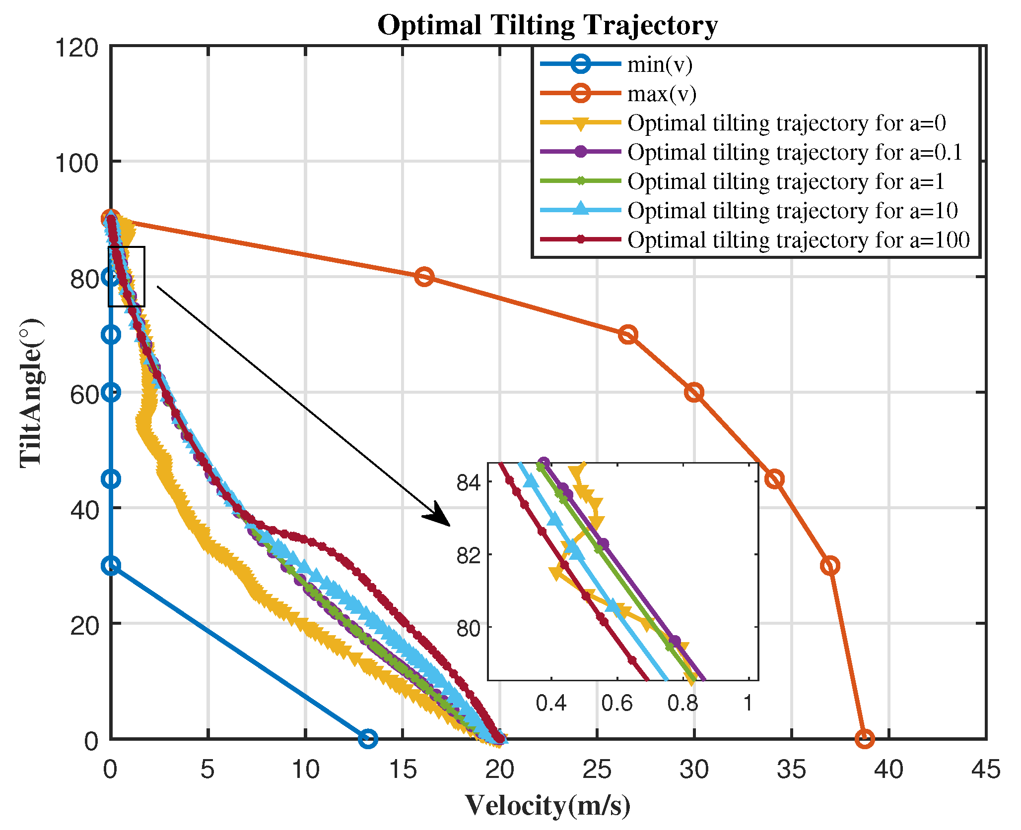
The transition process of the tilt-rotor VTOL UAV combines vertical takeoff and landing with high-speed cruise, which is an essential flight mode for this type of UAV. During the transition process, the front tilting mechanism is constantly shifted, and, as a result, the aerodynamic forces and configurations change. Therefore, transition flight is an extremely dangerous flight mode. The larger the tilting angle–velocity envelope of a tilt-rotor VTOL UAV, the easier it is to achieve the transition process.
Figure 4 shows the transition corridor of the tilt-rotor VTOL UAV.
The left and lower boundaries of the low-speed section of the transition corridor are obtained based on the stall angle of the attack limit. The upper boundary of the transition corridor in the high-speed segment is determined by constraining the lower limit of the angle of attack of the tilt-rotor VTOL UAV. The available power limit of the tilt-rotor VTOL UAV is used to determine the right boundary of the transition corridor in the high-speed segment. The transition flight can be completed by the tilt-rotor VTOL UAV within the transition corridor set under the above-mentioned conditions.
This paper is aimed at designing a tilting trajectory that is easy to track, so the most important parameters in the optimization results include transition time, tilting angle acceleration, and throttle command. When evaluating the superiority of the optimization results, comprehensive considerations can be obtained from the above aspects. For the problem studied in this paper, when taking the example of forward tilting (i.e., transition from helicopter mode to fixed-wing mode), the influence of different weight coefficients on the state and control variables is analyzed, and the optimal weight is obtained to ensure the stability and safety of the transition process. The physical parameters of the tilt-rotor VTOL UAV studied in this paper are
kg,
m
, and
kg· m
. The design of the weight for different simulation scenarios is shown in
Table 2.
In
Table 2,
a is the propeller thrust weight coefficient, which affects the speed of the aircraft,
b is the tilt angle acceleration weight coefficient, which affects the elevator deflection angle and thus changes the attitude of the aircraft, and
c is the transition time weight coefficient, which will affect the stability of the aircraft during the transition process.
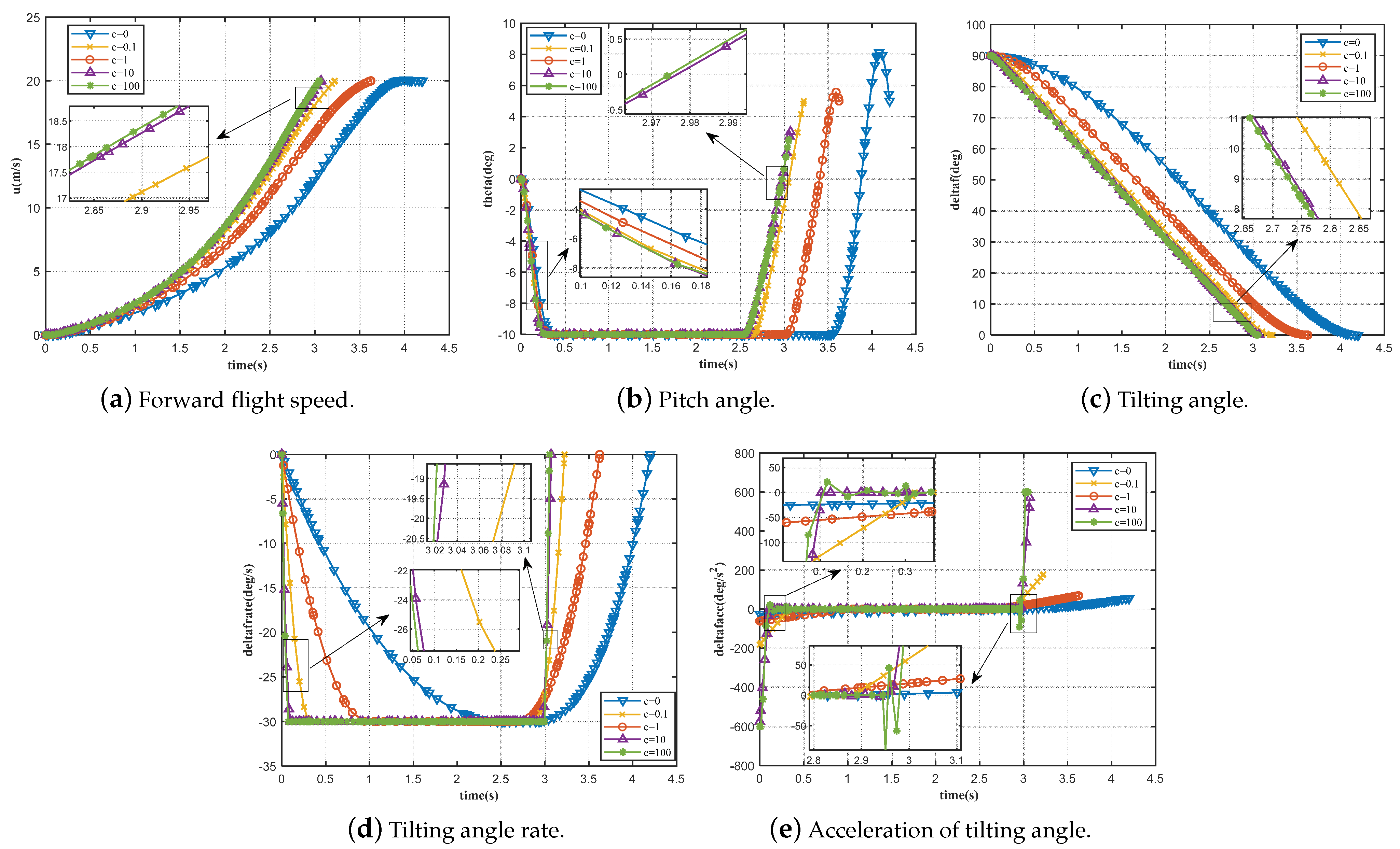
Due to the inherent modal changes and control architecture transitions, the stability of the tilt-rotor VTOL UAV in the transition phase is significantly poorer than in the vertical takeoff and landing phases. In addition, the anti-disturbance capabilities of the tilt-rotor VTOL UAV are the worst, making it the least safe flight phase. Therefore, minimizing the transition time is a reasonable indicator that should be considered in the transition trajectory design. Moreover, during the entire tilting process, to ensure safe and stable flight, the tilting process should be as gentle as possible to reduce sudden tilting variables. In scenario 1, the optimal tilting trajectory when the time weight coefficient
c is
, and 100 is shown in
Figure 5. It can be observed from
Figure 6a,c that, with the increase in the transition time weight, the time of the whole transition process decreases from
to
.
Figure 7a,b show that, during the initial stage of tilting, the throttle without a weight coefficient is always comparatively stable. When the weight of the transition time increases to a certain critical point, the front propeller throttle begins to increase rapidly to complete the transition process. The above analysis reveals that the weight of the transition time will significantly affect the transition time. In
Figure 6b, the terminal pitch angle decreases when the time weight coefficient is greater than a critical value, which is because the terminal speed of the UAV is too high at this time, and thus the pitch angle is reduced to maintain the altitude balance. It can be seen from
Figure 6d that an extremely large time weight coefficient will lead to an extremely fast tilting rate and insufficient attitude stability, and that large elevator deflection and throttle are required to maintain attitude stability. When the time weight coefficient is very small, the thrust coefficient of the front propeller will suddenly decrease in fixed-wing mode, and the thrust coefficient of the rear propeller will tend to increase abruptly, which clearly does not correspond to reality. If the time weight is extremely large, the state and control curves will not be smooth. Moreover, the rapid reduction of the rear throttle results in unstable attitude, so the selected range of the transition time weight in scenario 1 is 1–10.
The optimal tilting trajectory in scenario 2 when the propeller thrust weight
a is 0, 0.1, 1, 10, and 100 is shown in
Figure 8. According to the analysis in
Figure 8, the presence or absence of the propeller thrust weight has a significant impact on the tilting trajectory. At the initial moment of tilting, the optimal trajectory essentially coincides, where, as the weight of the propeller thrust increases, the corresponding speed at the same tilting angle also increases. As shown in
Figure 9d, with the increase in
a, in order for the aircraft to maintain the attitude stability, the tilting angle tilts faster, thereby making the aircraft gradually increase the throttle in the speed direction, and this increases the flight speed. In addition, when
a is 0, the optimal tilting trajectory exhibits significant oscillation. As can be seen from
Figure 10a,b,this is because the presence or absence of propeller thrust weight affects whether the propeller thrust is constrained or not. When
a is 0, the terminal speed of the UAV is insufficient, and the aerodynamic lift is not enough to maintain the altitude balance. Therefore, a head-up action is taken. As the speed of the UAV accumulates and increases, the aircraft lowers its head.As can be observed from
Figure 10c, the elevator deflection increases with the increase in the propeller weight. The elevator deflection reaches full deflection when the propeller thrust weight
a is equal to 10 or 100, while it takes longer to reach full deflection as
a increases. The above analysis leads to the conclusion that when the weight of the propeller thrust is too large, the control will be fully biased, which is very unfavorable for flight. However, when
a is 0, the system oscillates, and it is revealed that the propeller weight is conducive to maintaining the steady-state performance of the system. In summary, the propeller thrust weight in scenario 2 ranges from 0.1 to 1.
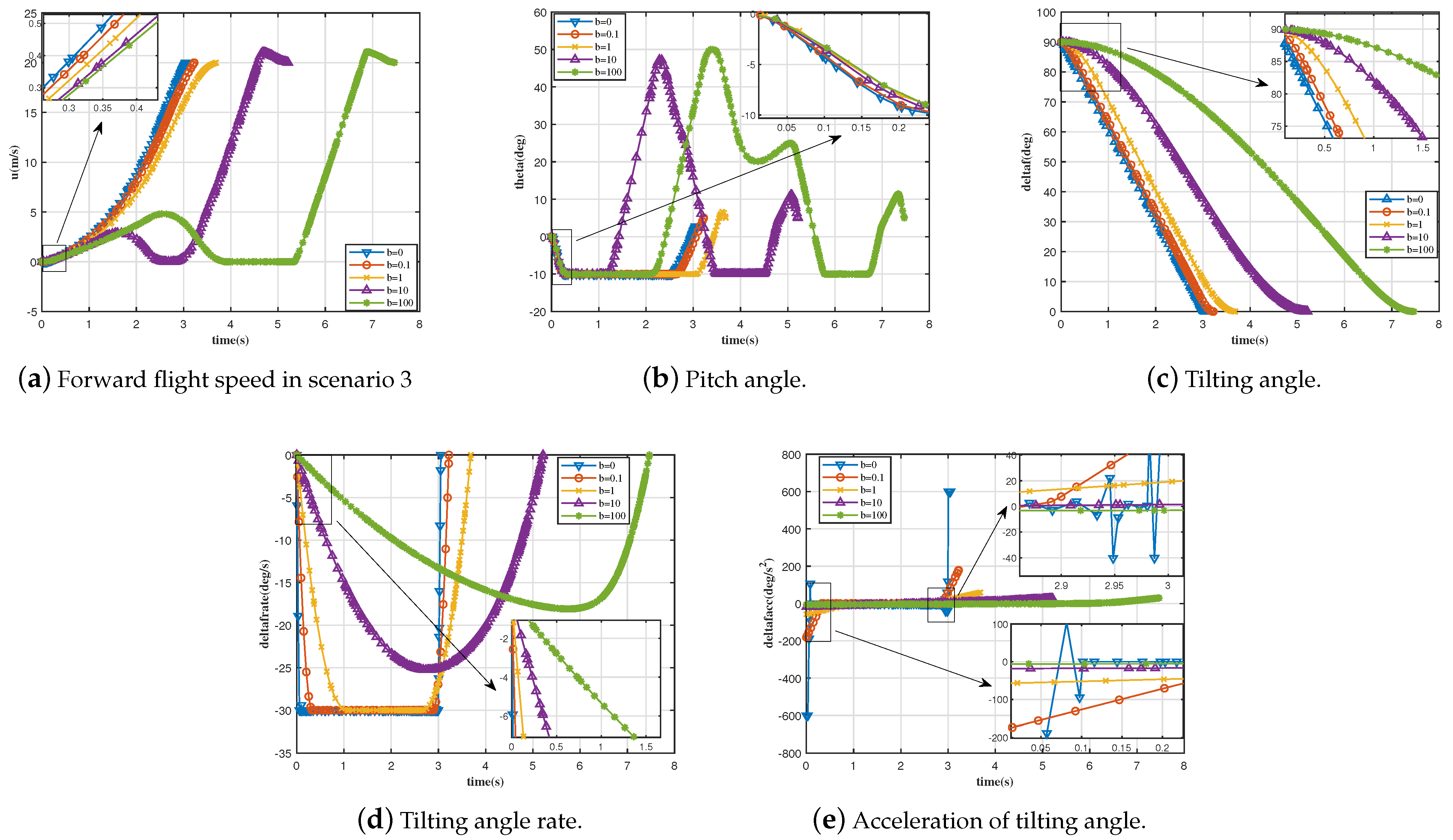
In scenario 3, the optimal tilting trajectory, where the tilting angle acceleration weight
b is 0, 0.1, 1, 10, and 100, is shown in
Figure 11. It can be seen from
Figure 11 and
Figure 12c that the tilting angle acceleration weight has a significant impact on the transition strategy but an opposite effect on the transition time weight. As
Figure 12d shows, the variation of the tilting angular speed changes from a step curve to a quadratic curve, suggesting that this weight is beneficial to constraining the sudden change in the tilting rate. As the weight increases, the tilting rate gradually slows down, which conduces to reducing the physical load of the servo.
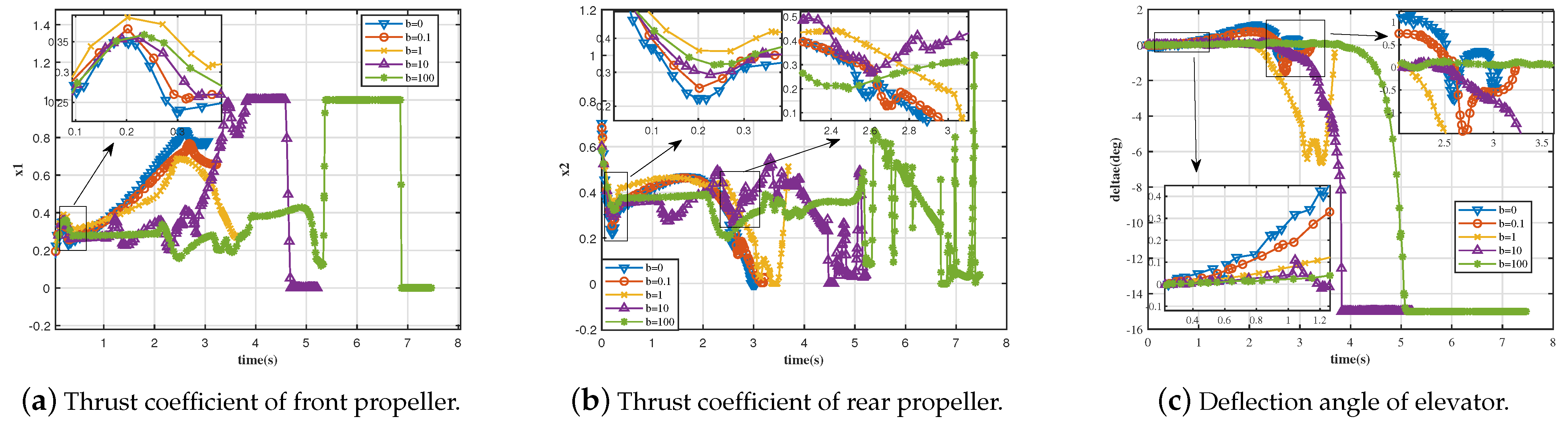
Figure 13a shows that the thrust coefficient of the front propeller decreases with the increase in the weight of the tilting angle acceleration. When
b is equal to 10 or 100, the thrust coefficient of the front propeller has a full deflection. Moreover, at the end of the transition, the thrust coefficient of the front propeller is 0, which is very unreasonable. According to
Figure 13b, as the weight of the tilting angle acceleration increases, the thrust coefficient of the rear propeller decreases. The thrust coefficient of the rear propeller oscillates dramatically when
b is equal to 10 or 100, which is unsafe for flying.
Figure 13c shows that when the tilting angle acceleration weight increases, the elevator deflection also increases. The elevator deflection displays full deflection for a particular value of
b, which is undesirable for flight. In summary, it is reasonable to observe that the weight range of tilting angle acceleration in scenario 3 is 0–0.1.


