1. Introduction
Owing to their cost-effectiveness, advanced functionalities, and ability to be reused, UAVs have garnered escalating popularity within the domain of reconnaissance and monitoring [
1,
2,
3,
4]. Over the past years, the operational landscape has witnessed a rise in complexity, thereby amplifying the demand for UAV implementation in these specific missions. Yet, a single UAV can hardly meet its actual task requirements when operating independently [
5,
6], as its sensor’s range of view may be easily blocked, limiting its ability to accomplish tasks. Cooperative efforts made by UAVs can significantly mitigate the risk of target loss [
7,
8,
9], thus leading to the adoption of multi-UAV collaboration [
10,
11] in trajectory planning for moving target tracking purposes.
Currently, the research hotspots in cooperative formation algorithms encompass communication strategies, formation control strategies, formation transformation trajectory planning, and cooperative obstacle avoidance. Formation transformation and cooperative obstacle avoidance have yielded significant and fruitful outcomes following extensive years of research. Muhammad Umer Farooq proposed a novel nonlinear quadcopter probabilistic roadmap (PRM) navigation method [
12], specifically designed to address the challenge of formation reconstruction for quadcopter formations after dynamic obstacle avoidance. Li J et al. [
13] conducted an investigation into collective obstacle avoidance algorithms for both first-order kinematic agents and second-order dynamic agents. They introduced an obstacle avoidance algorithm that eliminates the need for velocity measurements in agents with first-order kinematics. This algorithm is particularly beneficial when only a fixed proportion of agents can perceive obstacle information. Okechi Onuoha delved into the study of affine formation maneuver control for multi-agent systems with triple integrator dynamics, considering both continuous time and sampled data settings [
14]. As a result, the research demonstrated the effectiveness of maneuver-based formation transformations in facilitating obstacle avoidance.
Most cooperative obstacle avoidance strategies use the artificial potential field (APF) method. The APF method [
15,
16,
17] is extensively employed in UAV formation obstacle avoidance. The algorithm relies on establishing gravitational and repulsive fields to calculate the resultant force that guides path planning at each moment. However, the APF algorithm can fall into a local optimal solution if the field function design is unreasonable. Moreover, the algorithm lacks consideration for the dynamic motion constraints of UAVs, making it challenging to track the planned path in real-time.
DWA was proposed in 1997 [
18]. The algorithm considers the limitation of velocity and acceleration of a moving body and employs an evaluation function to select the most favorable trajectory. Nonetheless, the algorithm exhibits several limitations, including the inherent challenge of designing a suitable evaluation function, a tendency towards a conservative speed window, and a propensity to converge towards suboptimal positions within a localized context. Reference [
19] proposes the collision avoidance dynamic window approach (CADWA) algorithm, which addresses problems such as collision avoidance failure and improper evaluation function weighting. Furthermore, reference [
20] introduces an additional evaluation factor of direction change, which mitigates issues related to the contradiction between heading and speed factors in DWA, such as untimely obstacle avoidance and frequent direction changes on certain road conditions, resulting in smoother trajectories.
Additionally, an effective improvement direction involves merging the DWA algorithm with other algorithms, such as the A* algorithm first proposed by Hart in 1968 [
21]. Extracting the key points of path planning by the improved A* algorithm as temporary target points of DWA algorithm, achieving the fusion of the improved A* and DWA algorithm on the basis of global optimization, thus realizing dynamic path planning in complex environments has been realized by reference [
22]. In reference [
23], the traditional A* algorithm’s drawbacks, such as non-optimal path and many redundant points, were addressed by expanding its search neighborhood to remove the limitation of motion direction and combining it with the DWA’s improved speed evaluation function for temporary obstacle avoidance. Reference [
24] tested the hybrid path planning algorithm of A* and DWA on four typical Turlebot2 mobile robot terrains. The experiment demonstrated that the hybrid algorithm outperforms the individual algorithms by offering efficient obstacle avoidance and a faster path-finding process.
This paper introduces a novel algorithm for UAV Formation Control, specifically designed to enable efficient task completion by multi-UAV formations operating in complex environments that include a variety of obstacles. The proposed algorithm comprehensively considers the sensor measurement range and the kinematic constraints of UAVs, effectively tackling the challenge of maintaining formation integrity in the presence of disturbances and navigating obstacles. The key contributions of this paper can be summarized as follows.
We propose an enhanced version of the traditional DWA algorithm, with a specific focus on improving the navigation evaluation function. To achieve this, we incorporate the concept of target distance, which serves to correct the azimuth angle. Additionally, we integrate the A* algorithm to address the limitations of the fixed weight mechanism and enhance the overall efficiency of the process. Furthermore, we introduce a novel rotation evaluation function to constrain large rotation angles, thereby further improving the search efficiency. The ultimate goal of these enhancements is to bolster the obstacle avoidance capability of two-dimensional planar UAVs.
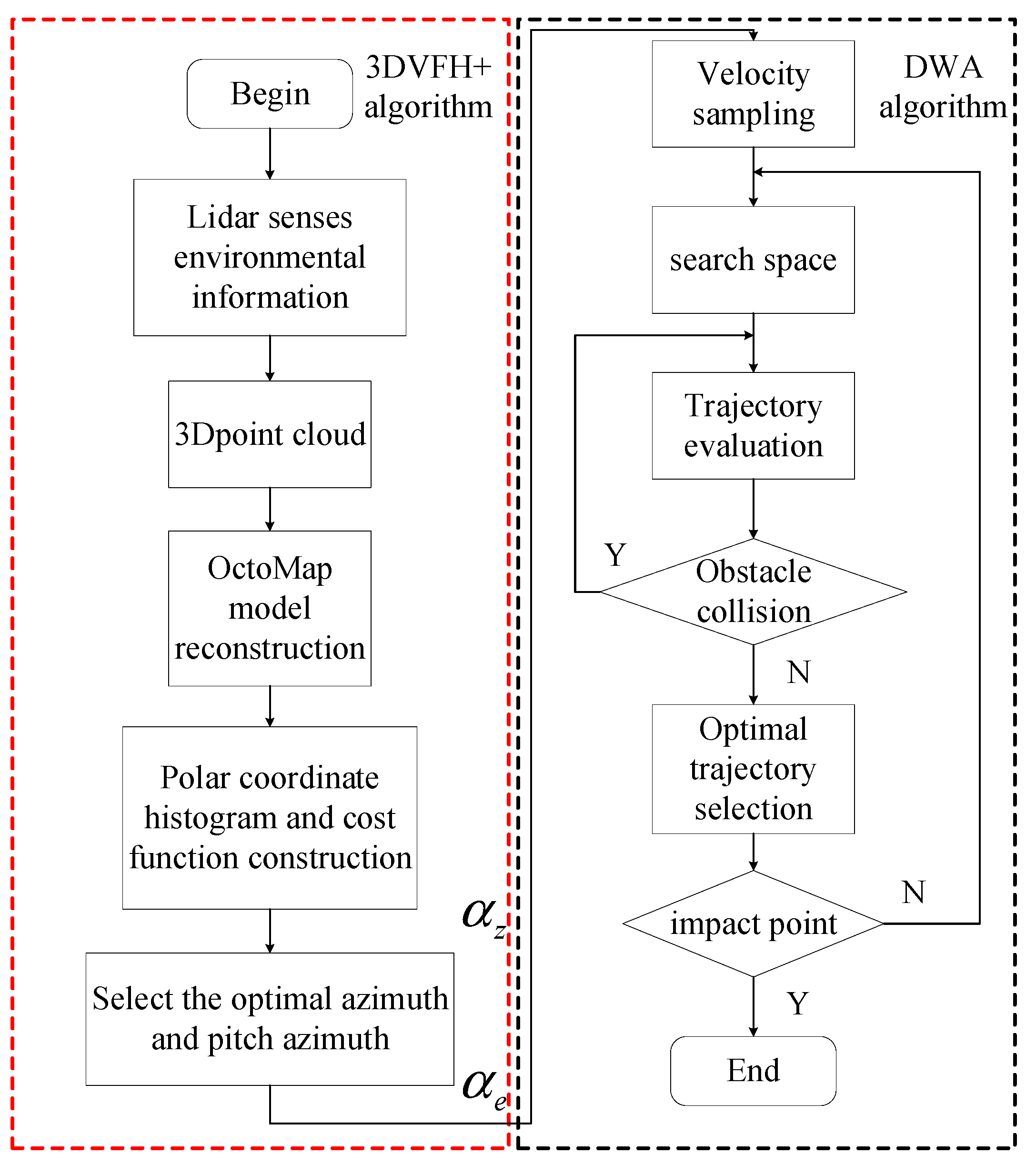
Combined with the 3D VFH + algorithm and improved DWA, it improves the obstacle avoidance ability of two-dimensional plane UAV and solves the obstacle avoidance problem of multi-aircraft formation in three-dimensional space.
The rest of this paper is organized as follows.
Section 2 describes the improved DWA algorithm.
Section 3 describes the algorithm design for 3D VFH+.
Section 4 introduces the UAV formation control fusion algorithm.
Section 5 verifies and analyzes our algorithm. Finally, concluding remarks are provided in
Section 6.
2. Design of Improved DWA
2.1. Basic Principle of Standard DWA
The DWA algorithm primarily samples within the two-dimensional velocity space and identifies a constrained set of velocity combinations that fulfill predetermined criteria. After this step, the method determines the optimal speed at the current time through the utilization of an evaluation function.
Firstly, due to the limitation of its own hardware, the moving body has the constraint of linear velocity in kinematics:
Secondly, there is a maximum acceleration constraint:
indicates the linear velocity of current motion, indicates the angular velocity of current motion, indicates the minimum linear acceleration of current motion, indicates the maximum linear acceleration of current motion, indicates the minimum angular acceleration of current motion, indicates the maximum angular acceleration of current motion, and the sampling interval, represented as “”, remains consistent without any alterations.
Finally, there is an obstacle constraint:
where
denotes the closest distance between the moving body and the obstacle.
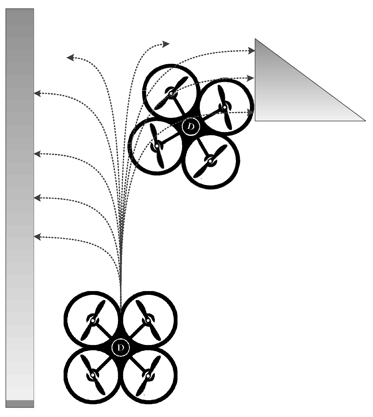
Through the utilization of the DWA, it becomes feasible to simulate a multitude of prospective paths within the given map, as shown in
Figure 1.
Then, the current optimal speed combination is selected according to the velocity evaluation function of (4).
In the equation, represents the azimuth evaluation function, which guides the motion of the object towards the target direction. The represents the obstacle avoidance evaluation function to guide the motion of the object away from the obstacle. The denotes the kinematic body linear velocity evaluation function to stimulate its rapid passage; are the fixed weights of the evaluation function and is the normalization coefficient.
2.2. Improving the DWA
(1) Introduction of target distance
The azimuth evaluation function in the standard DWA is shown as:
where
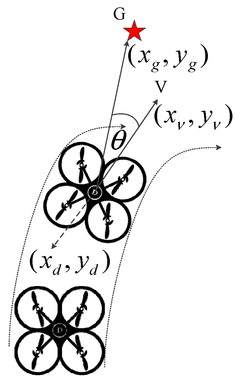
is the angle between the velocity vector and the vector connecting the current position of the moving object to the target point. The smaller the value of
, the higher the evaluation score. Given that the current position of the moving object is denoted as D:
, the position of the velocity trajectory’s endpoint is denoted as V:
, and the position of the target point is denoted as G:
, Equation (6) can be derived as shown in the
Figure 2.
Combining (5) with (6) yields:
Under the action of (7), as the moving object approaches the target point, the angle
experiences rapid expansion, resulting in oscillations of the moving object at the target point. Therefore, the introduction of target distance is employed as a constraint to mitigate this issue, as shown in (8):
(2) Dynamic weights of the fusion A* algorithm
The A* algorithm is usually used for global path planning. By rasterizing the global map and identifying a number of nodes to be expanded, the raster point with the lowest current cost can be selected according to the cost function as shown in (9), denoted as A:
.
where
represents the distance cost from the starting point to the current grid point, while
represents the distance cost from the current grid point to the target point. The global path coordinates obtained from the A* algorithm is merged with the final coordinates of the velocity trajectory obtained from the DWA algorithm. By utilizing the cosine relationship, the dynamic weight
for the azimuth evaluation function can be obtained as shown in (10).
The introduction of dynamic weights improves navigation efficiency.
(3) New function
Considering that large turning angles affect the actual following result of the path by the moving body, the
function is added to the evaluation function of the DWA algorithm. This function will compensate for the large rotation angle, so as to avoid the large rotation angle of the moving body in path planning. The evaluation function is shown as:
where
is the dynamic weight in the evaluation function. The final improved DWA evaluation function obtained is shown as:
The introduction of a new rotation cost function improves the DWA algorithm curve smoothness in path planning, allowing for better tracking of actual body movements. In the upcoming section, we will examine effective approaches for vertical obstacle avoidance.
3. Algorithm Design for 3D VFH+
3.1. OctoMap Build Map and Search
During a cooperative obstacle avoidance operation, the UAV will obtain point cloud data using its sensors. Nevertheless, since the limitation of UAVs computational power and sensor measurement range, it may not have explored all surrounding spatial points in an obstacle filled environment. To alleviate the resultant computational load, this section adopts the OctoMap data structure to compress point cloud data and build a map.
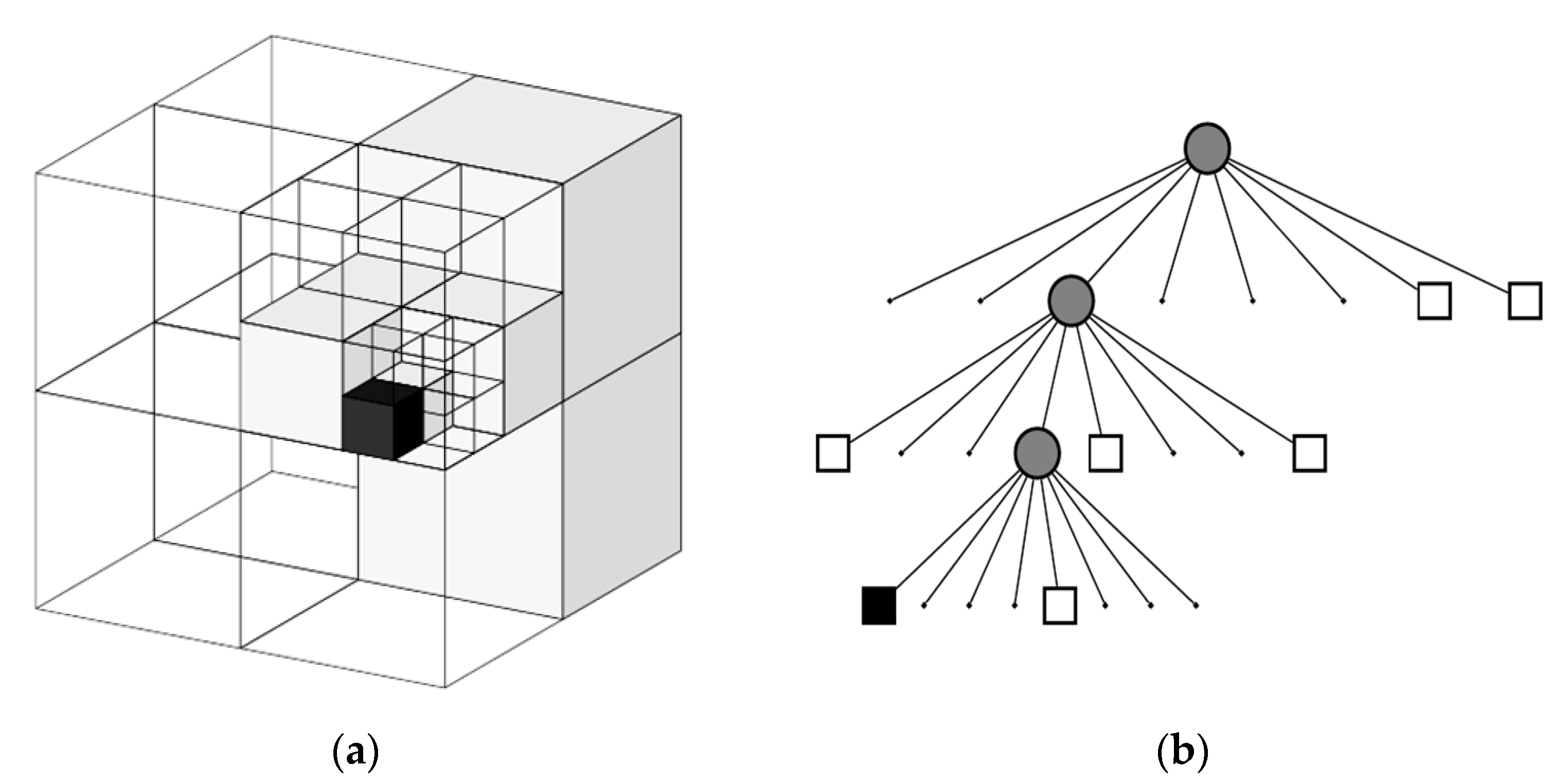
OctoMap is a 3D map generation software based on octree, which can display full 3D images including features that are not mapped or overlaid and can estimate the fusion of sensor data through multiple measurements within the grid. The system is characterized by high resolution, compressed data, and small storage space. The octree structure is a spatial partitioning method which has been explored in various operations since the 1980s. It divides the three-dimensional space into eight quadrants wherein each quadrant represents a node in the octree. The octree starts from the root node and when this node is located in an empty three-dimensional space, it is referred to as an empty node. When located in the same dimension, it is known as a black node. Otherwise, it is called a gray node. It is divided into 2 × 2 × 2 sub-nodes based on the orientation of each coordinate axis. This process continues recursively until a node is either empty, or the stereoscopic space in which it is located is homogeneous or reaches a predetermined minimum scale.
Figure 3 shows examples of a simple object represented in an octree, illustrating the octree in terms of a three-dimensional raster structure and a tree structure.
In general, the value 0 is used to indicate non-occupation, 1 indicates occupation, and the floating-point number between 0 and 1 indicates the probability of occupation at that specific time. A higher floating-point number indicates a higher probability of the node being occupied by an obstacle. Because the spatial structure description is transformed into octree representation, it can be pruned quickly for three special states: 0, 0.5, and 1 node, thus achieving the purpose of saving space.
3.2. Construction of Two-Dimensional Principal Pole Histogram
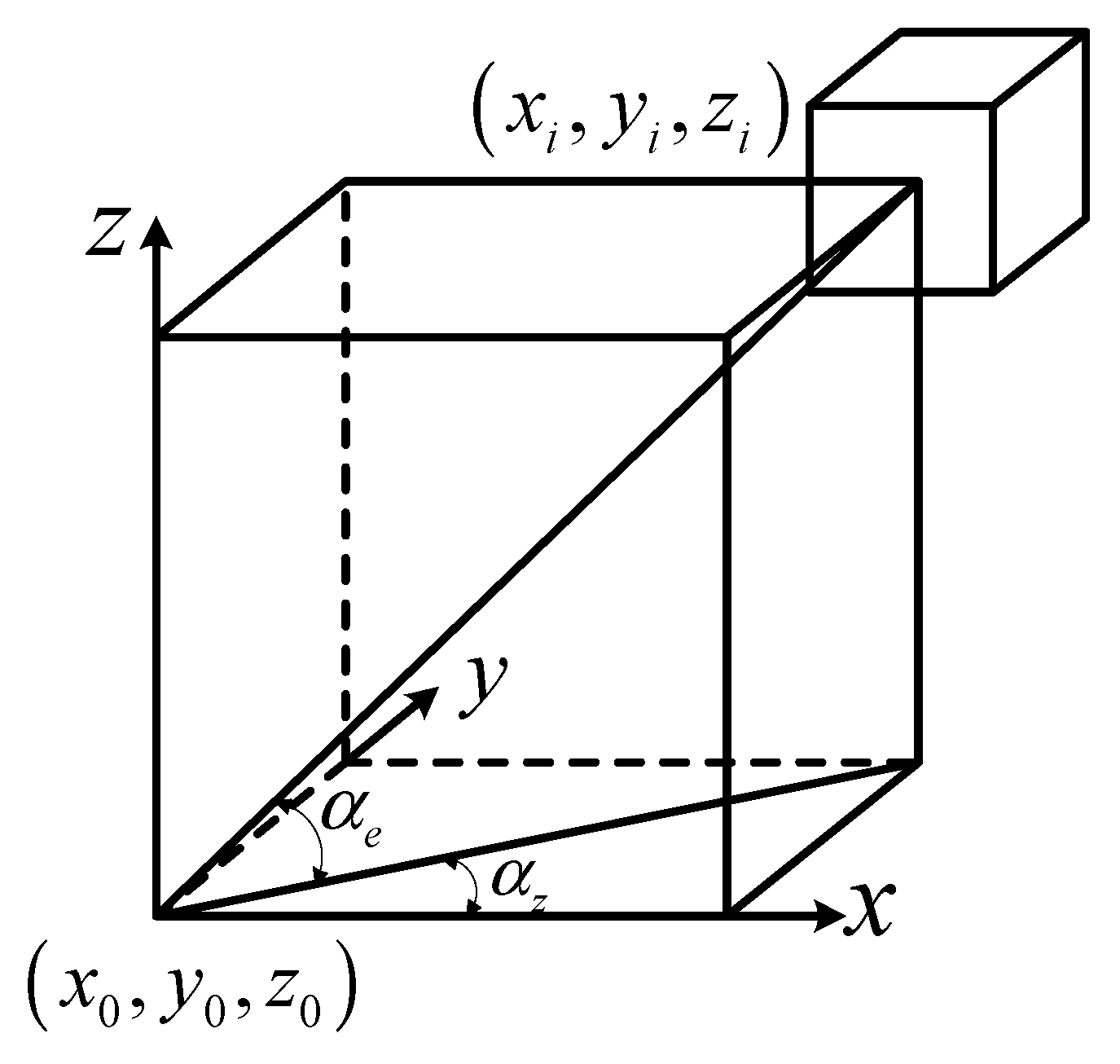
The OctoMap introduced in the previous section can divide the environmental space into cubes, and this section will calculate the respective weights for each cube to construct a two-dimensional main polar histogram. The UAV’s current location is the center and
is the radius to build a UAV’s exploration range. Only some of the cubes on the surface of the sphere are involved in the construction of the 2D main polar histogram. When the UAV is the center, the coordinates of each cube on the surface of the sphere constructed by the UAV can be determined by two angles. The coordinates of the center of a cube
on the surface of the sphere is
, the angle between the projection of the cube and the center of the UAV in the
plane and the
axis is
, which is the azimuth angle. The angle between the cube and the center of the UAV and its projection in the
plane is
, which is the pitch angle. The horizontal coordinates
and vertical coordinates
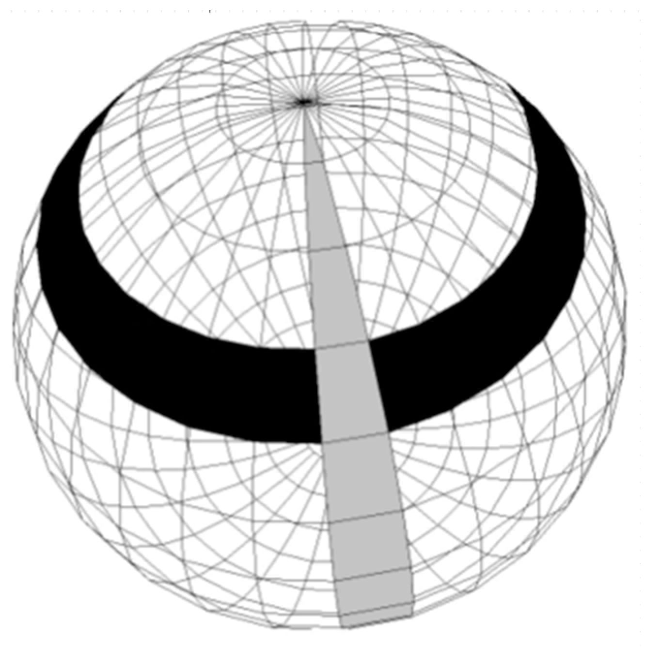
of the two-dimensional main polar histogram can be obtained by making certain factor transformations, as
Figure 4,
Figure 5 and
Figure 6 show.
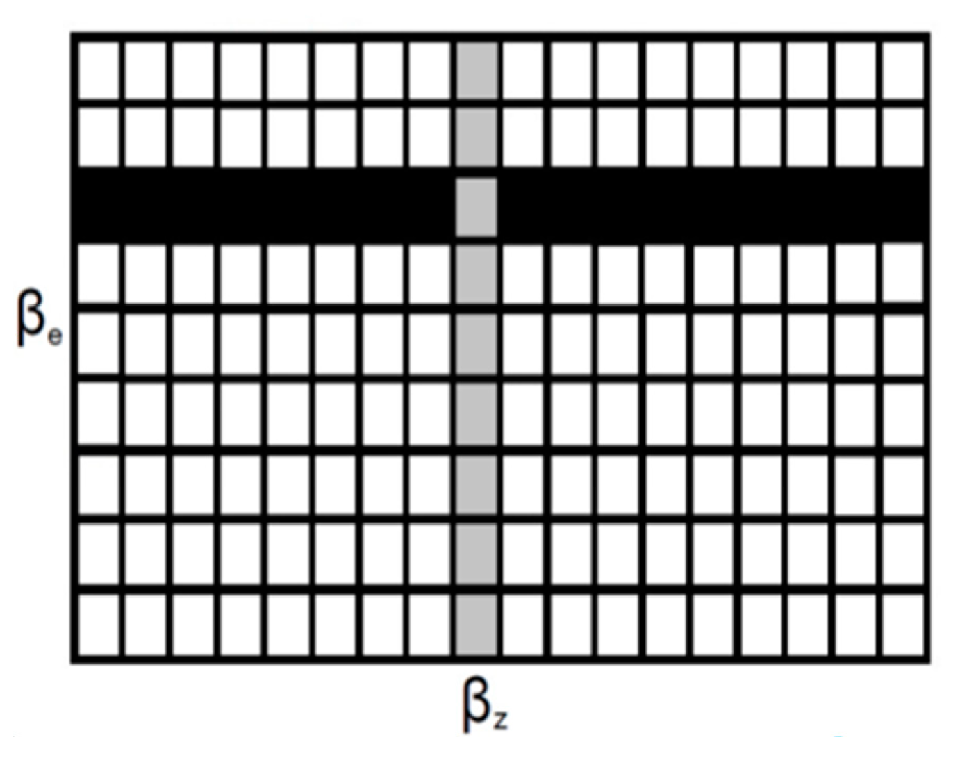
According to
Figure 6, the equations for calculating the azimuth and the x-axis coordinates of the two-dimensional main polar histogram are as follows:
The equations for calculating the pitch azimuth and the y-axis coordinates of the two-dimensional main polar histogram are as follows:
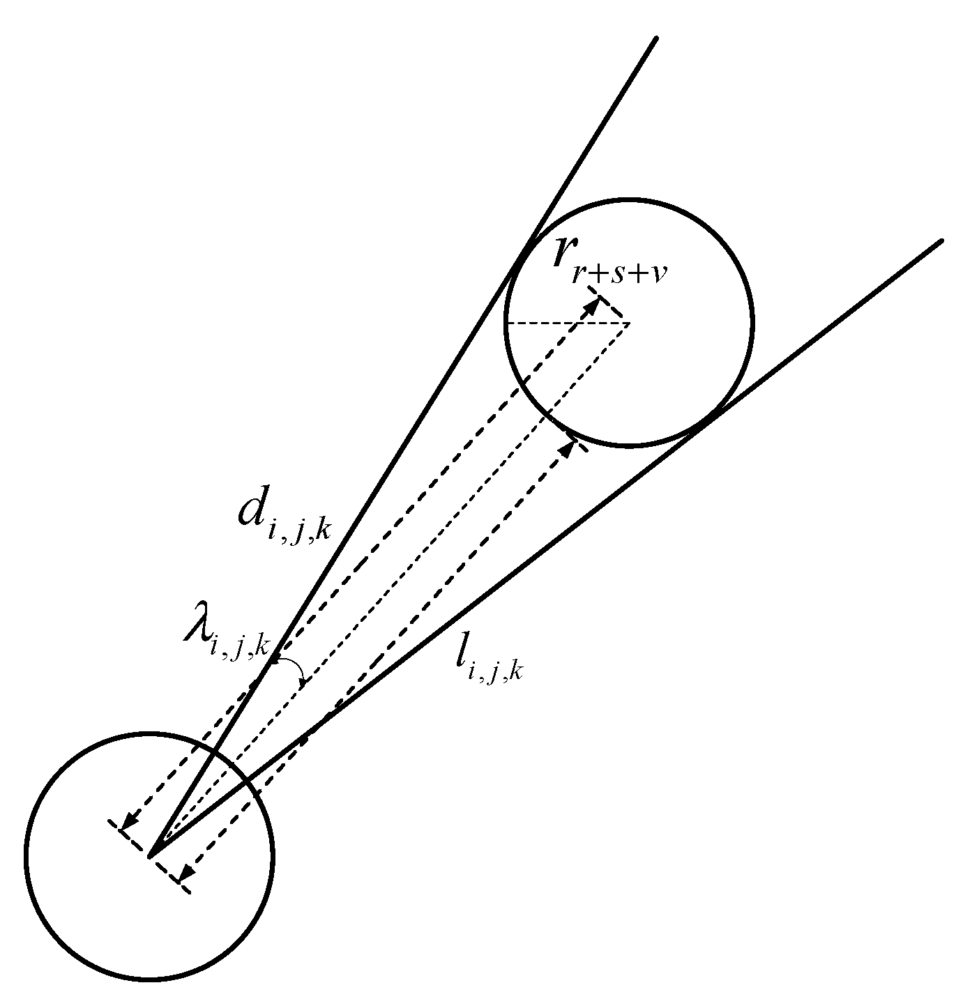
The transformation factor, denoted by 1/α, is used to convert azimuth and pitch angles into the coordinates of the 2D main polar histogram. The size of the UAV is not taken into consideration during the calculation process. The 3DVFH+ algorithm compensates for it by increasing the size of the cube segmented by OctoMap. Additionally, the algorithm determines the maximum and minimum angles of the cube using the calculated compensation factor. The expanded cube size is depicted in
Figure 7.
For cube expansion, the main considerations are the drone size
, the safety radius
, the cube size
, and the final expanded radius:
The compensation factor
is calculated as follows:
where
is the distance between the center of UAV and the center of cube. From
Figure 8 above, we can get:
The weight of each cube mapped to the two-dimensional principal pole histogram is calculated as follows:
where
is a collection of spherical surface cubes constructed by UAV exploration space,
and
are constants that satisfy the following relations:
3.3. Kinematic Constraint Design
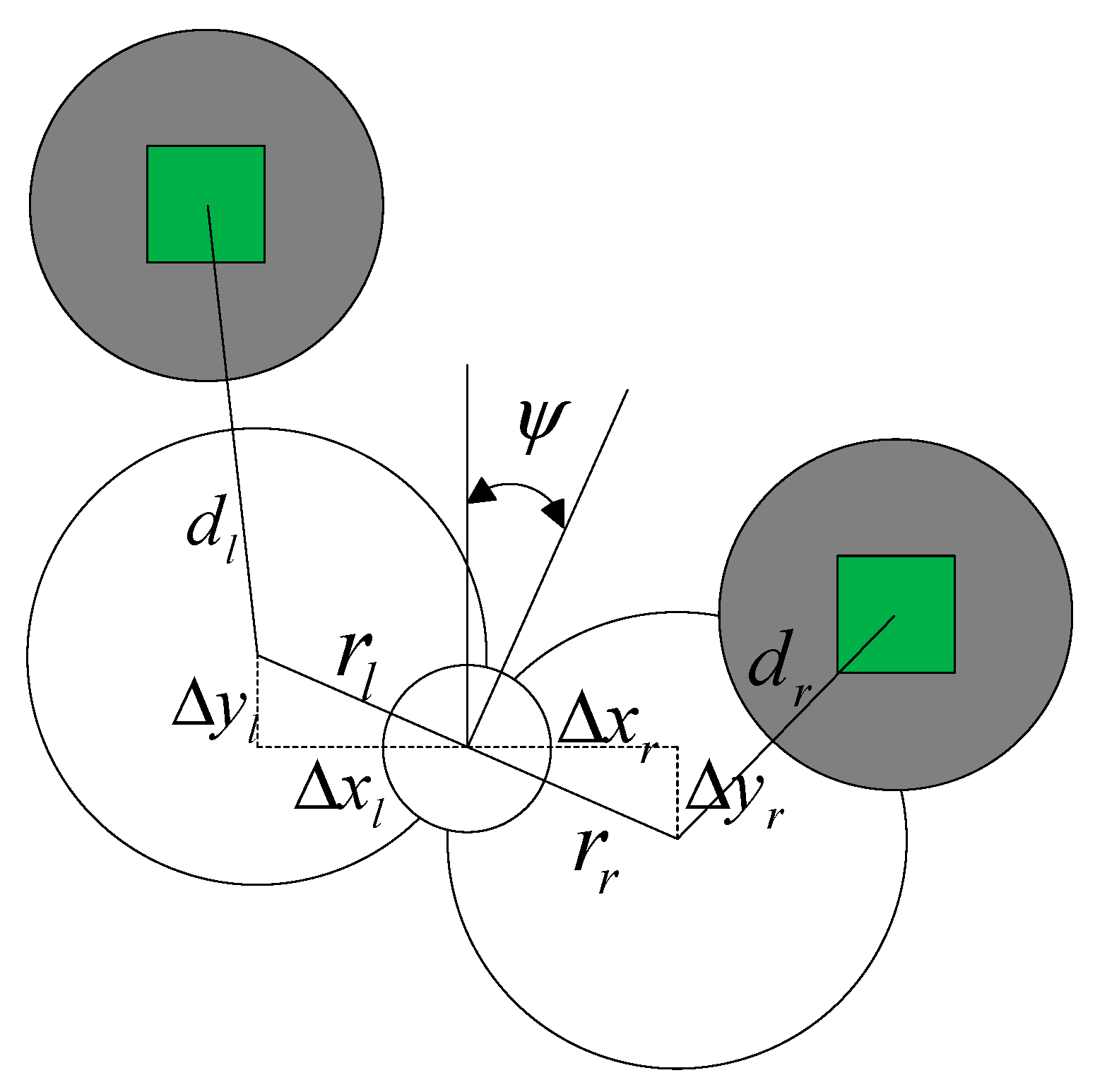
This section focuses on the kinematic constraints of UAV during obstacle avoidance. The
plane turn obstacle avoidance model, which is established in the VFH+ algorithm, is shown in
Figure 8.
The distance from the center of the drone to the two cubes is as follows:
when the possible turning circles of the UAV intersect the occupied cube, the left and right limiting angles
and
are obtained, and initialization season
:
If the drone meets at this time, update if it does. If the drone meets at this time, update .
Considering the limited climb speed of the quadrotor, a limit is placed on the UAV pitch azimuth. Firstly, the turning distance to the obstacle is calculated using the arc length formula
, then the altitude difference is divided with
to calculate the altitude direction climbing motion coefficient
.
The max azimuth difference is
and the maximum turning distance
and the maximum height
for each cube are as follows:
The final formula for calculating the maximum achievable pitch azimuth is as follows:
3.4. Path Detection and Selection
The weights corresponding to each cube in the environment space were calculated in the previous section, and the two-dimensional principal-pole histogram was constructed, and the azimuth upper and lower limits of plane and the maximum limits of pitch azimuth in direction were given considering the kinematic constraints. In this section, we will select the cube cell with the lowest path weight value from the constructed histogram as the moving trajectory in three-dimensional space. We use evaluation functions to determine the current optimal azimuth and pitch azimuth angles.
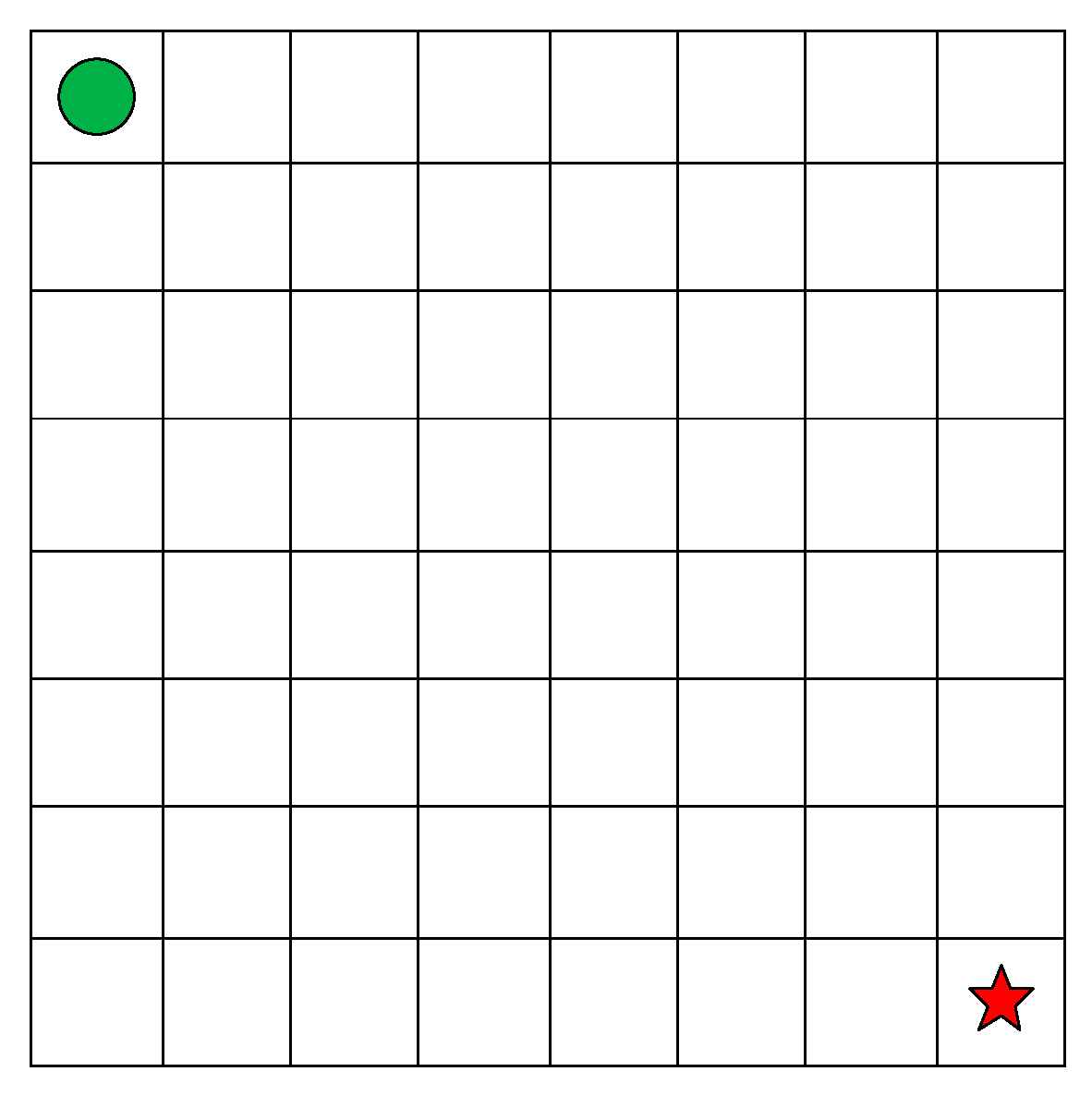
Let us begin our journey starting at the top-left corner and reaching the destination at the bottom-right, as depicted in
Figure 9. We are permitted to move in the top, bottom, left, and right directions, excluding top-left, which moves in the opposite direction. As a result, only the bottom-right corner yields two possible moves. For this reason, each element in the first row of the grid can only be accessed by moving right from the top-left element. Similarly, each element in the first column can only be reached by moving down from the top-left element. During this time, the path becomes unique, and hence the minimum path sum corresponding to each element is the sum of the numbers on the corresponding path. For elements not present in the first row and first column, an adjacent element above each can be reached by moving down by one step, while an adjacent element left of it can be reached by moving right by one step. The minimum path sum corresponding to the element is equal to either the minimum path sum corresponding to the adjacent element above it or the element left of it plus the value of the current element, whichever yields the smallest value. Since each minimum path sum is related to its adjacent elements, dynamic programming can be employed to solve this problem using the subsequent recursive equation:
where
denotes the minimum path sum from the upper left corner to the position of
. The transition from the previous historical state to the current state exists only in two cases
and
, and the minimum is taken plus the current grid weight. The azimuth and pitch azimuth in each grid are selected by the following cost function for the smaller surrogate value.
The first coefficient is determined based on the difference between the pitch azimuth of the line from the current position to the target point and the pitch azimuth of the candidate direction . The second coefficient is calculated as the difference between the yaw angle of the UAV and the azimuth of the candidate direction . Finally, the third coefficient represents the difference between the direction selected in the last historical moment and the currently considered candidate direction v. These three coefficients can be employed to adjust the direction of inclined climbing or horizontal turning motion as selected.
6. Conclusions and Future Research
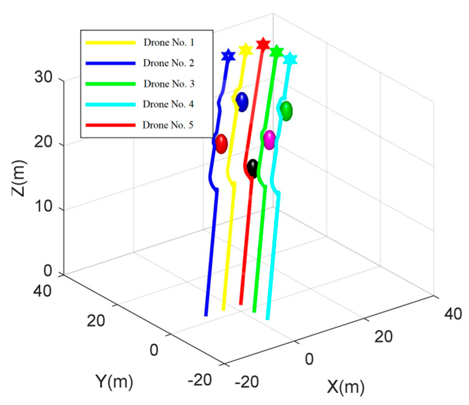
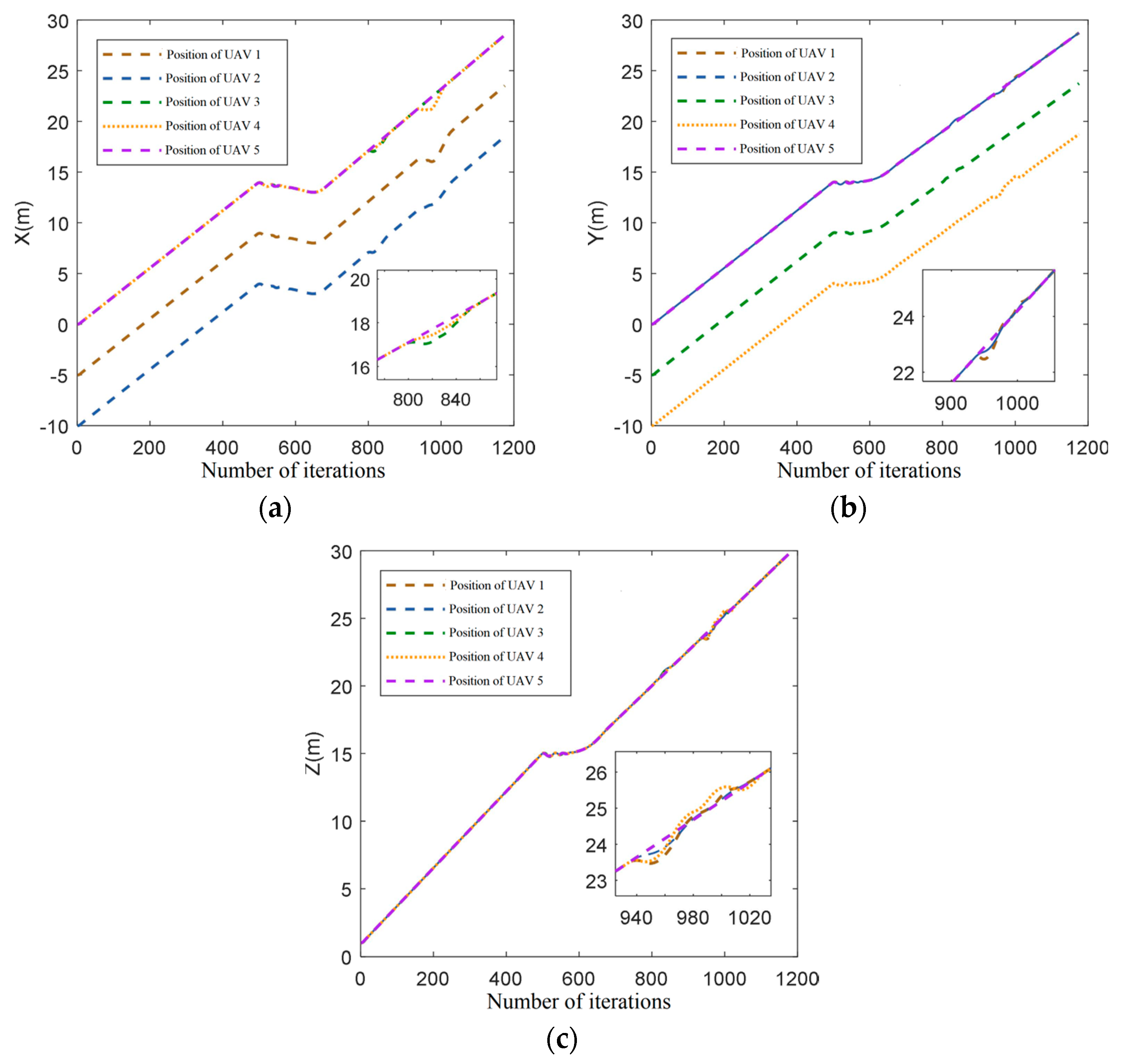
This paper introduces an improved DWA algorithm that optimizes obstacle avoidance for UAVs. Firstly, the azimuth evaluation function in the DWA algorithm is optimized by introducing the target distance. Additionally, the A* algorithm is integrated to replace the fixed weights in the azimuth evaluation function, thereby improving the search efficiency of the DWA algorithm. A rotation cost function is introduced into the evaluation function, which effectively smoothens the path and resolves the two-dimensional plane formation obstacle avoidance problem for UAVs by constraining large-angle rotation frequency. Moreover, the 3DVFH+ algorithm is incorporated to efficiently acquire the pitch azimuth and extend the cooperative obstacle avoidance function for two-dimensional plane formation to three-dimensional space formation. Simulation results demonstrate the effectiveness of this approach in multi-aircraft formation obstacle avoidance path planning.
This paper presents a fusion algorithm for multi-UAV cooperative formation obstacle avoidance path planning. The algorithm’s effectiveness is verified through simulation, yielding favorable results. However, the current research process has certain limitations. Notably, when dealing with dynamic obstacles, the speed of both moving obstacles and the advancing UAV formation is insufficient, necessitating further consideration for obstacle avoidance with medium- and high-speed obstacles. In future research, introducing more improvement strategies can enhance the algorithm’s performance. Additionally, physical simulation in a real environment will be explored to further verify the algorithm’s effectiveness.
