1. Introduction
Demand for unmanned aerial vehicle (UAV) delivery is on the rise from 2025 to 2050. UAVs fly point-to-point in a straight line through the air, which is less affected by terrain factors. Moreover, this is a distinct advantage for freight transport in remote areas and congested urban areas [
1]. The tilt rotor aerial UAV (TRUAV) is a novel aircraft that combines two flight modes: copter mode and airplane mode. The versatile flight mode brings many application-level benefits. In the copter mode, the TRUAV can take off and land vertically and hover like a helicopter, which means the vehicle does not need a runway for takeoff and landing, broadening the application scenario. At the same time, it can have a fast cruise and large capacity like a fixed-wing aircraft in airplane mode. This means the vehicle can have long endurance. These are all beneficial to the TRUAV for cargo transportation applications. However, the new structural design introduces new technical difficulties, especially in the transition phase. As the tilt angle of front rotors changes, the airflow of the rotor interacts with the wing. At this phase, the aerodynamic characteristics of the TRUAV are complex and nonlinear.
The controller proposed in this paper focuses on the transition process. During the transition, the aerodynamic characteristics of the TRUAV are complex, with severe air-elastic coupling and significant non-linearity. There are mature and stable control schemes for attitude control in both copter mode and airplane mode. The challenges in this work are the configuration change from copter mode to airplane mode and the dramatic aerodynamic change from stationary to constant-speed cruise. During the transition, the front motor tilt angle changes and the wing interacts with the propellers, which makes the aerodynamics complex and uncertain and brings difficulties to the control model design. At the same time, the front motor tilt angle changes, making the TRUAV attitude control performance change, especially pitch attitude control. For the TRUAV, the change in takeoff weight also affects its attitude control performance. In summary, these are the difficulties of modeling and controller design.
Most control systems in aerospace applications are based on linearized systems designed by picking certain equilibria [
2,
3]. It is a common approach in TRUAVs to design different controllers for specific operating conditions. But then the design of controller switching or scheduling strategies is required. As a classical control theory, PID is the most widely used in engineering without accurate dynamics modeling [
4]. Due to the underactuated property, the tracking of UAV attitude and velocity is generally achieved through a cascade structure [
5,
6,
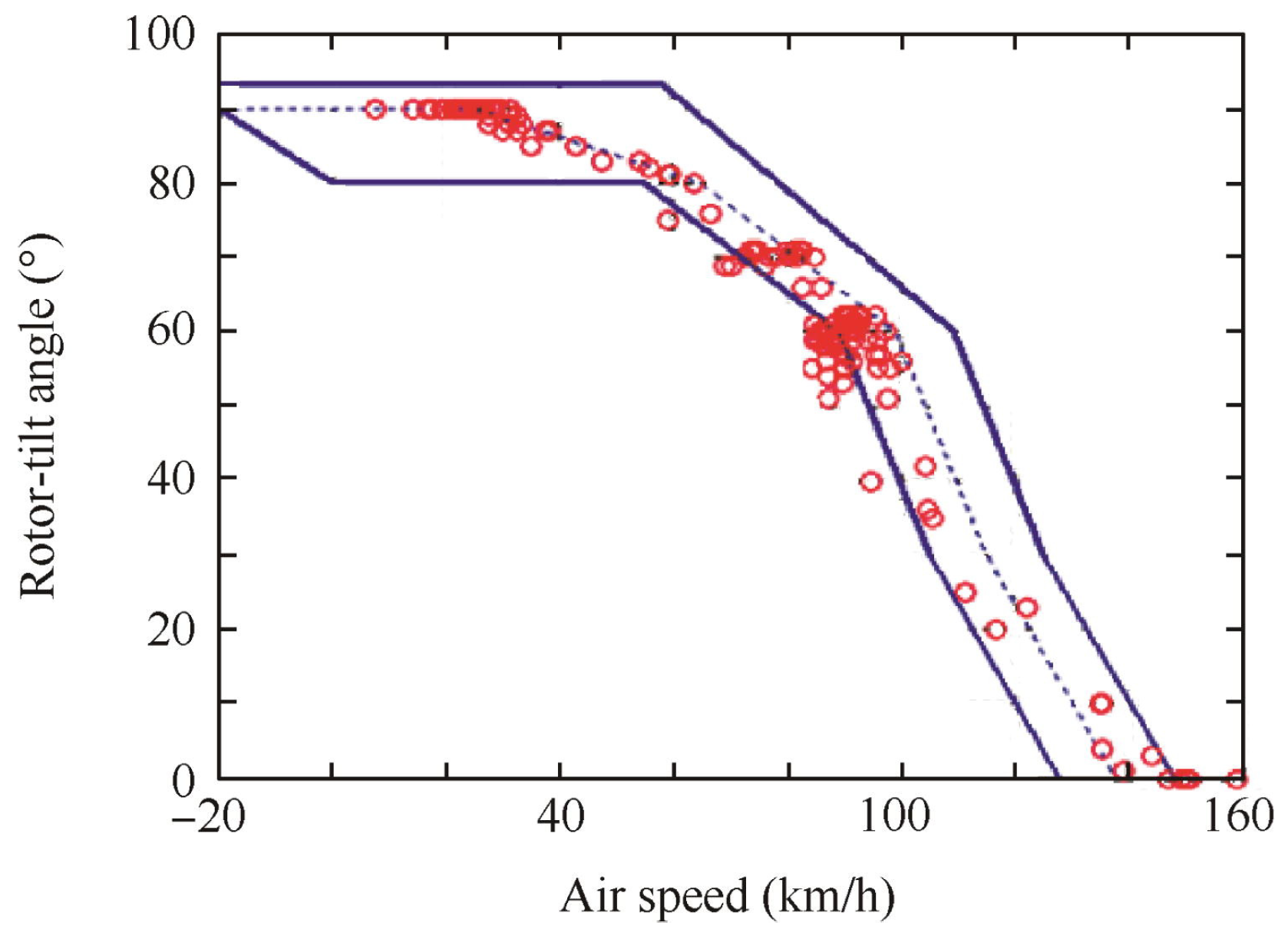
7]. According to the actual application scenario, the controller gain is adjusted to achieve the desired control effect. In the transition process, the direction of the front rotor thrust vector is changing, and a single cascade PID cannot adapt to the entire transition process and cannot meet the dynamic performance requirements of the TRUAV. Some scholars adopted the scheduled control approach to determine the possible flight range and flight envelope stability conditions of tilt-rotor UAVs based on trim point analysis [
4], as shown in
Figure 1. Due to the constraints of the actuator and lift generation, appropriate leveling points are selected to evaluate the stability corridor. The flight envelope is discretized into the required number of operating points, and an independent controller is developed for each operating point. These independent controllers are generally PID [
8,
9,
10], LQR [
11,
12] and SMC [
13]. As the flight configuration changes during the transition, the appropriate control law is loaded through the controller scheduling policies. In addition, the required controller switching may affect stability, if scheduling parameters change quickly concerning controller convergence. However, due to the limited number of linearized points, the overall control structure is limited to a specific region of the flight envelope [
14].
Another approach to controller design is based on adaptive or nonlinear implementations of unified control methods that can handle nonlinear dynamics and cover the entire flight envelope, such as optimal control gain scheduling [
15,
16], dynamic inversion [
17,
18,
19], robust control [
20,
21,
22] and nonlinear model predictive control (NMPC) [
23,
24]. This method avoids the instability caused by the unreasonable selection of the equilibrium point. An improved back propagation (BP) neural network PID control algorithm is proposed by Peng et al. [
25]. The method exploits the strong nonlinear mapping properties of the neural network to enhance the robustness of the tilt rotor vehicle transition process. Yu [
26] and Yuksek [
27] et al. used neural networks to compensate for dynamic inverse errors and external disturbances. The development of deep neural networks has led to a significant increase in the ability of reinforcement learning to be used for aircraft attitude control, particularly for highly nonlinear control problems. Koch et al. [
28] developed GymFC, a reinforcement learning training environment for training an intelligent neural network attitude controller for UAV attitude control. The performance of the intelligent attitude controller was compared with that of a PID controller in the GymFC environment. The results show that the intelligent neural network attitude controller has excellent performance. Xu et al. [
29] directly applied a neural network controller to control hybrid UAVs. The designed neural network controller is robust and can take advantage of complex dynamics. The tilt rotor studied by Huo et al. [
30] and Lee et al. [
31] only makes structural changes while hovering. Huo et al. used deep reinforcement learning algorithms for trajectory tracking control of a trans-domain tilt-rotor robot control. Simulation results show that the neural network controller trained by the reinforcement learning algorithm is highly adaptable to complex environments. Lee et al. first attempted to apply reinforcement learning for low-level attitude control of a tilting multi-rotor. Reinforcement learning is increasingly used in the field of UAV control, while few relevant studies directly apply reinforcement learning to the TRUAV attitude control during the transition process.
In summary, scheduled control and unified control are two main types of control methods regarding the TRUAV, and their main features are presented separately. However, existing research has mainly focused on applying the pattern recognition capabilities of machine learning to improve these two types of controllers. Fewer studies have directly used reinforcement learning to interact with the environment to learn the optimal control strategy, especially for attitude control of the TRUAV during the transition process.
Therefore, the purpose of this paper is to design a controller using the reinforcement learning PPO algorithm and to design and improve the reward function for the TRUAV attitude control. The performance and adaptability of the proposed controller are tested through simulation. The structure of this study is as follows: the TRUAV transition process is modeled and simulated, followed by the reinforcement learning PPO algorithm and the design of the reward function for the transition process. This is followed by the analytical evaluation, which is divided into four parts, namely convergence analysis, the effect of improvement on the reward function, the adaptability of the proposed controller and the effectiveness of our proposed method compared to A2C, standard PPO algorithm.
2. Dynamic Model
Typical tilt rotor UAV models [
14,
32,
33] are listed in
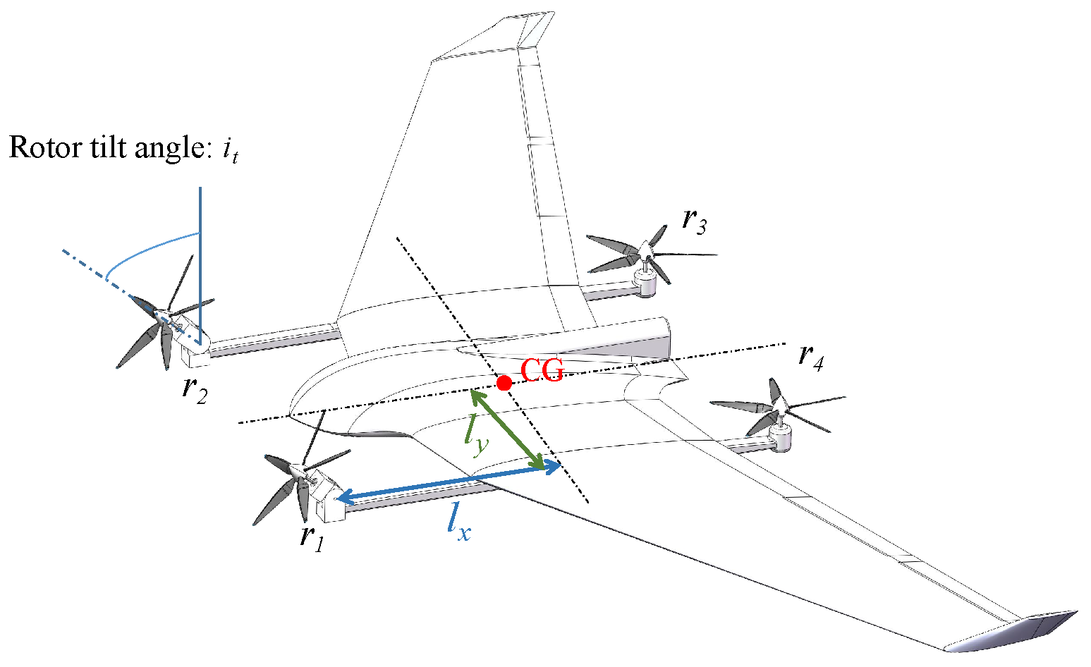
Table 1, and the layout of the TRUAV in this paper is shown in
Figure 2.
A flying wing layout is used with the four motors arranged at a distance from the wing to minimize mutual interference between the wing and the rotor. The center of gravity of the TRUAV is located in the center of the four motors. During the transition process, the tilt angle of two motors, and , located in front of the wing, gradually tilts from 0° to 90°. The pull and are horizontal forward, and the rear motors and stop rotating at the end of the transition process.
The rigid body motion model of the TRUAV can be represented using Newton’s Euler equation. The equation is as follows.
where
m is the mass,
J is the inertia matrix (Ignoring the effect of rotors tilting),
is the 3 × 3 identity matrix,
is the linear velocity,
is the angular velocity,
is the force and
is the moment.
Moreover,
and
are the combined force and moment on the vehicle, consisting of the rotor aerodynamic force and moment, the wing aerodynamic force and moment and gravity. The equation is as follows.
where
is gravity,
and
is the thrust and moment of the rotor in the body coordinate system
B,
and
is the aerodynamic force and moment in the airframe coordinate system. The following equation can establish the rotor aerodynamic force and moment.
where
is the propeller thrust and
is the 6 × 4 distribution matrix, as shown below:
where
is the distance between the rotor and the center of mass along the x-axis of the body,
is the distance between the rotor and the center of mass along the y-axis of the body,
k is the propeller torque factor and
is the tilt angle.
The aerodynamic forces and moment are described by
where
is the transition matrix from the airframe coordinate system to the body coordinate system,
is the dynamic pressure,
S is the wing area and
,
,
,
,
,
are the drag coefficient, side force coefficient, lift coefficient, roll moment coefficient, pitch moment coefficient and yaw moment coefficient, respectively.
3. Method
The policy proximal optimization (PPO) algorithm is a model-free, on-policy method. PPO has high performance and low computational complexity. The policy network takes the observation state s as input and outputs the action a. For a continuous action space, the task of the policy network is to output the probability distribution from which the action is sampled. In this paper, the PPO algorithm is used to control the attitude of the TRUAV during the transition process accelerating from hover to cruise speed. To avoid divergence, it also uses the clip function to reduce the difference between old and new policies. The reward function is designed for the transition process according to the characteristics of the TRUAV.
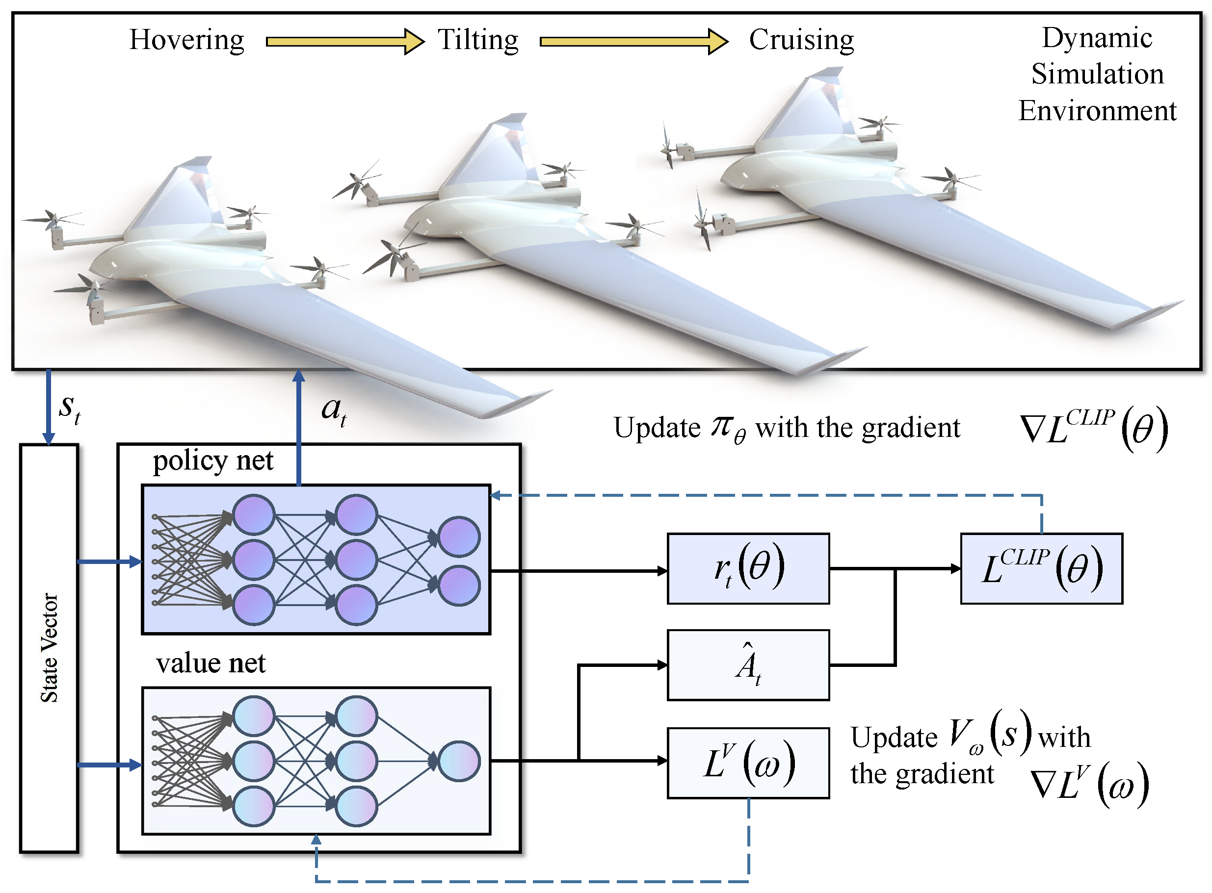
3.1. Algorithm Framework
In this paper, a standard reinforcement learning structure is used for controller training. The algorithmic framework is shown in
Figure 3. The control task involved in this paper conforms to a Markov decision process (MDP). The composition is (
S,
A,
P,
R,
), where
S is the state,
A is the action and
is the state transition function for the next state s’ given the current state
s and the action
a,
R(
s,
a) is the reward value,
is the discount factor. The policy
gives the possibility of choosing action
a at state
s. Thus, the goal of the algorithm is to find the policy loss
that optimizes the parameters
θ of the policy.
The policy gradient algorithm is based on the principle of policy gradient estimation and then computing the gradient for parameter
θ updating. The gradient is estimated in a Monte Carlo method, and the policy loss J is obtained by the agent applying the policy to interact in the environment.
In practice, these gradients are obtained by the gradient solver, which updates the parameters
θ of the neural network by backpropagation.
The critical challenge of the policy gradient is to reduce the variance of the gradient estimate in order to obtain a better policy. The generalized advantage estimation method (GAE) is utilized in the PPO to reduce the variance. The advantage function is built to reconstruct the reward signal.
The advantage function evaluates a behavior compared to other behavior available in the state, such that good behavior receives positive rewards and poor behavior has negative rewards. It is, therefore, essential to estimate the value function of the average reward. The value network is an independent supervised learning neural network estimated by collecting the reward value samples. Multiple agents are also used in PPO to collect samples simultaneously to increase the number of samples. The loss function of the PPO is as follows:
where
denotes the ratio between the old and new strategies.
is a hyperparameter with a small value used to keep the new policy close to the old policy. The importance sampling method is used in the PPO algorithm to obtain the expectation of samples collected from the old policy, which improves sample utilization. The new policy is refined based on the old policy, and in this way, each sample can be used in multiple gradient ascent steps. As the new policy is refined, the two policies will deviate more, thus increasing the difference in estimates, so the old policy is periodically updated to match the new policy. The PPO algorithm reduces the computational complexity compared to the second-order optimization involved in the TRPO solution. The PPO uses a first-order optimization method with confidence intervals, which restricts the ratio between the old and new strategies
to the range
by clip.
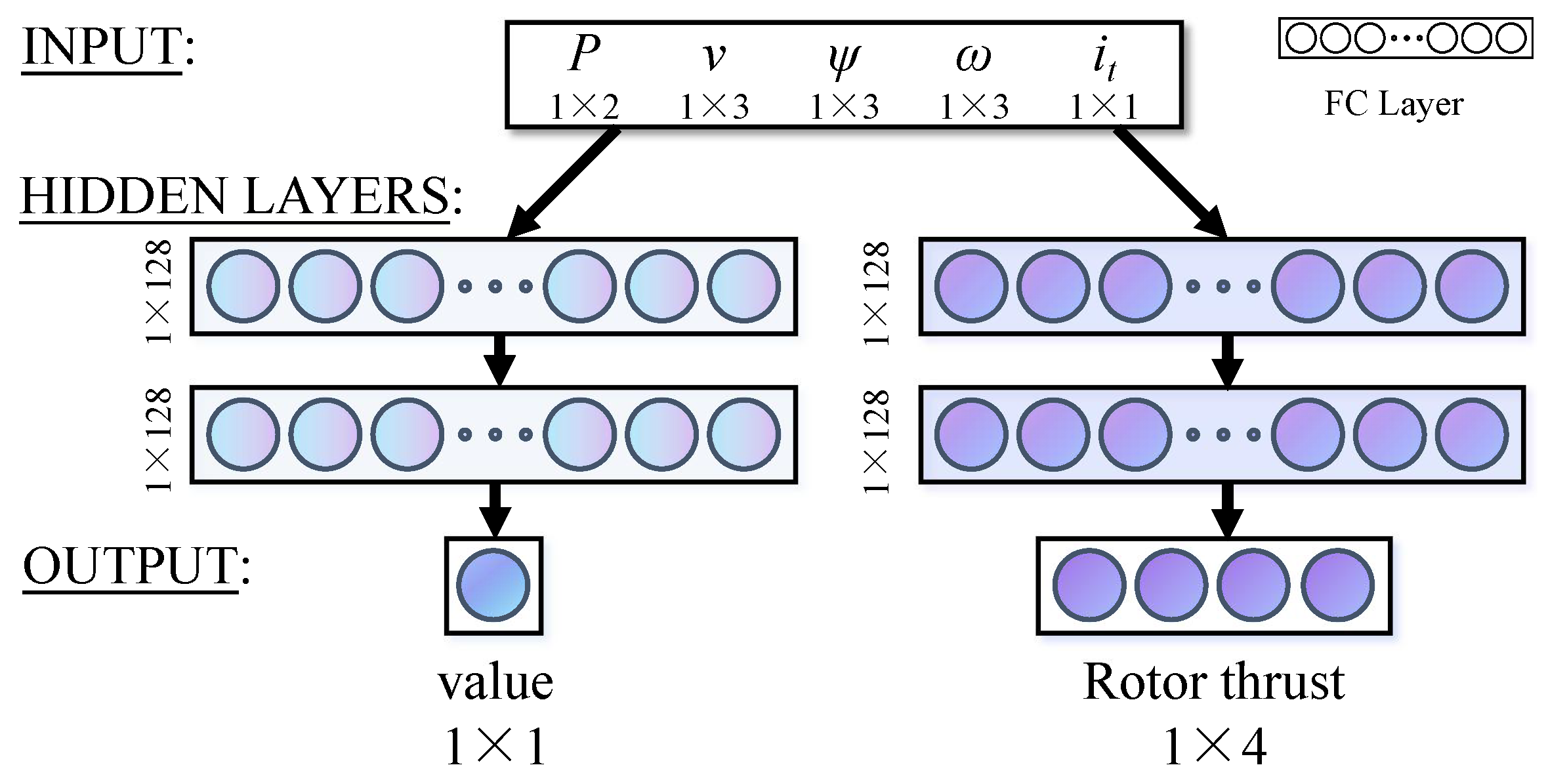
3.2. Network Architecture
Because the PPO algorithm is based on the actor–critic method, the neural network used in this paper consists of policy and value networks, as shown in
Figure 4. The policy network and the value network have the same structure, both have two fully connected layers with 128 units each, and the activation function is the Relu function. The output of the value network is the value of the current state vector
s which is used to train the output of the policy network
a(
a1,
a2,
a3,
a4). The action space of the policy network output is within a small symmetric range, such as (−1, 1). Following this design increases versatility by limiting the action outputs to a maximum and minimum range, which can then be adapted to the action range of the actuator through a mix-and-match operation such as scaling. After the operation, we can find the speed of motor
r(
r1,
r2,
r3,
r4).
The input of the neural network is a 12-dimensional state vector
s.
where (
y,
z) is position, (
u,
v,
w) is velocity,
is the Euler angle, (
p,
q,
r) is the angular velocity and
is the current rotor tilt angle. To ensure the stability of the attitude of the vehicle during the transition, it is not only necessary to focus on the fact that the vehicle attitude angle
needs to be at the desired value for a short period. It also needs to ensure that the velocity vector (
u,
v,
w) is pointing forward, and the change in altitude and slip during the transition is not too severe. As the transition process is horizontal and forward, the x-axis position is constantly increasing, which has a large impact on the estimation error and the time required for training if not normalized. In this paper, the x-axis displacement has a small effect on attitude control, so the x-axis displacement is not used as a state input. Further, if the tilt angle is removed and only the pitch angle is used as a state input, the neural network must control both the motor output
a and the tilt angle
. And this will increase the dimension of the action space and make learning the optimal strategy difficult in the absence of expert data.
3.3. Reward Function
The reward function is designed and optimized for the characteristics of the TRUAV transition process, given by the following Equation (
11).
where
d is the survival reward;
is the deviation from the y-axis and z-axis positions in the ground coordinate system;
is the forward velocity and min(
vxt,
vmax) is a clap function to limit the maximum reward of the forward velocity.
is the deviation from the y-axis and z-axis velocity in the ground coordinate system;
is the vehicle attitude angular deviation;
is the vehicle attitude angular velocity deviation;
is the action output characterizing the vehicle energy consumption and
is the amount of change from the previous moment of action representing action change magnitude.
The reward function in this paper focuses on guiding the vehicle forward with a positive x-axis velocity reward while maintaining flight stability and flight altitude. So speed-related rewards are divided into two parts, min(vxt, vmax) and . min(vxt, vmax) is a clap function to limit the maximum reward of the forward velocity.
A common problem in optimal control is the controller output constant oscillation between maximum and minimum. This causes unnecessary wear and tear on the actuators in practice. This is not a significant problem in a simulator environment but is problematic in actual flight. In real aircraft, online training can have a significant impact on the stability of the aircraft due to perturbations in the ambient wind. The output of the PPO policy network is a Gaussian distribution of the action, which is sampled to obtain the output. The high variance of the distribution leads to high oscillations in the output actions. In this paper, is introduced into the reward function as a penalty term to reduce the RL controller output jitter.
The aerodynamic force during the transition process is complex while the TRUAV accelerates from hover to cruise speed. Attitude and altitude considerations differ at the beginning and end of the TRUAV transition process. To reduce the deviation between attitude angles and desired values at the end of the process, a tilt-angle-related coefficient is proposed, and the attitude error penalty term introduces the variable coefficient.
3.4. Training
In this part, the controller of the TRUAV is trained with the PPO algorithm. This simulation environment is developed based on the open-source project framework named flightmare [
34]. The agent interacts with the simulation environment for attitude controller training via reinforcement learning algorithms. To simulate a fully loaded situation, the maximum output thrust of each motor will be limited to a maximum thrust of 0.3 times the take-off weight of the vehicle. The goal of the training is to complete the transition process in 4 s with a simulation step length of 0.02 s, i.e., 200 steps. At the same time, the stability of the TRUAV attitude is ensured with the rotor tilt angle of the vehicle turning from 0° to 90°.
The training task is to perform attitude control of the UAV to complete the transition from copter to airplane mode under a random initial state, as shown in
Table 2.
Finally, the well-trained neural network controller was tested under different conditions, such as rotor tilt angle rate, rotor axis lengths and take-off weights, to verify its robustness and adaptability. Specific network hyperparameters are referenced in
Table 3 below.
4. Results and Discussion
In this section, the convergence of the PPO algorithm for attitude control of TRUAV in the transition process is analyzed. Also, according to the characteristics of the TRUAV, the reward function is improved. There are two main points. One is to reduce the controller output jitter, and the other is to reduce the attitude angle deviation from desired values at the end of the transition process. Three simulations are reported to verify the adaptability of the designed RL controller during the transition process. In the first simulation, the adaptability of the RL controller to different takeoff weights was tested. In the second simulation, the adaptability of the RL controller to different diagonal wheelbases was tested. In the third simulation, the adaptability of the RL controller to different rotor tilt rates, i.e., rotor tilt strategies, was tested. Finally, the proposed method is compared with the A2C and standard PPO.
4.1. Convergence Analysis
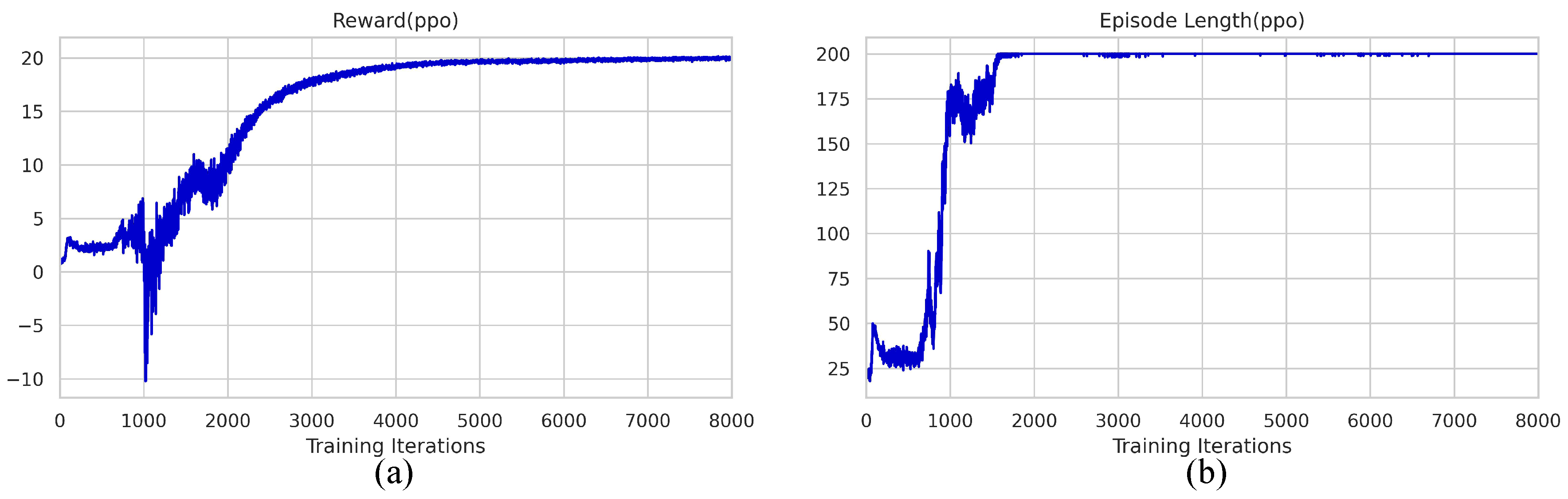
Since the TRUAV model is highly nonlinear and tends to diverge during training, a lower learning rate and clip value were chosen. The average reward and the average episode length are shown in
Figure 5. After 1500 iterations, the RL controller can keep the tilt-rotor UAV from falling during the transition process as shown in
Figure 5b.
Figure 5a shows that the maximum reward is reached after 5000 iterations.
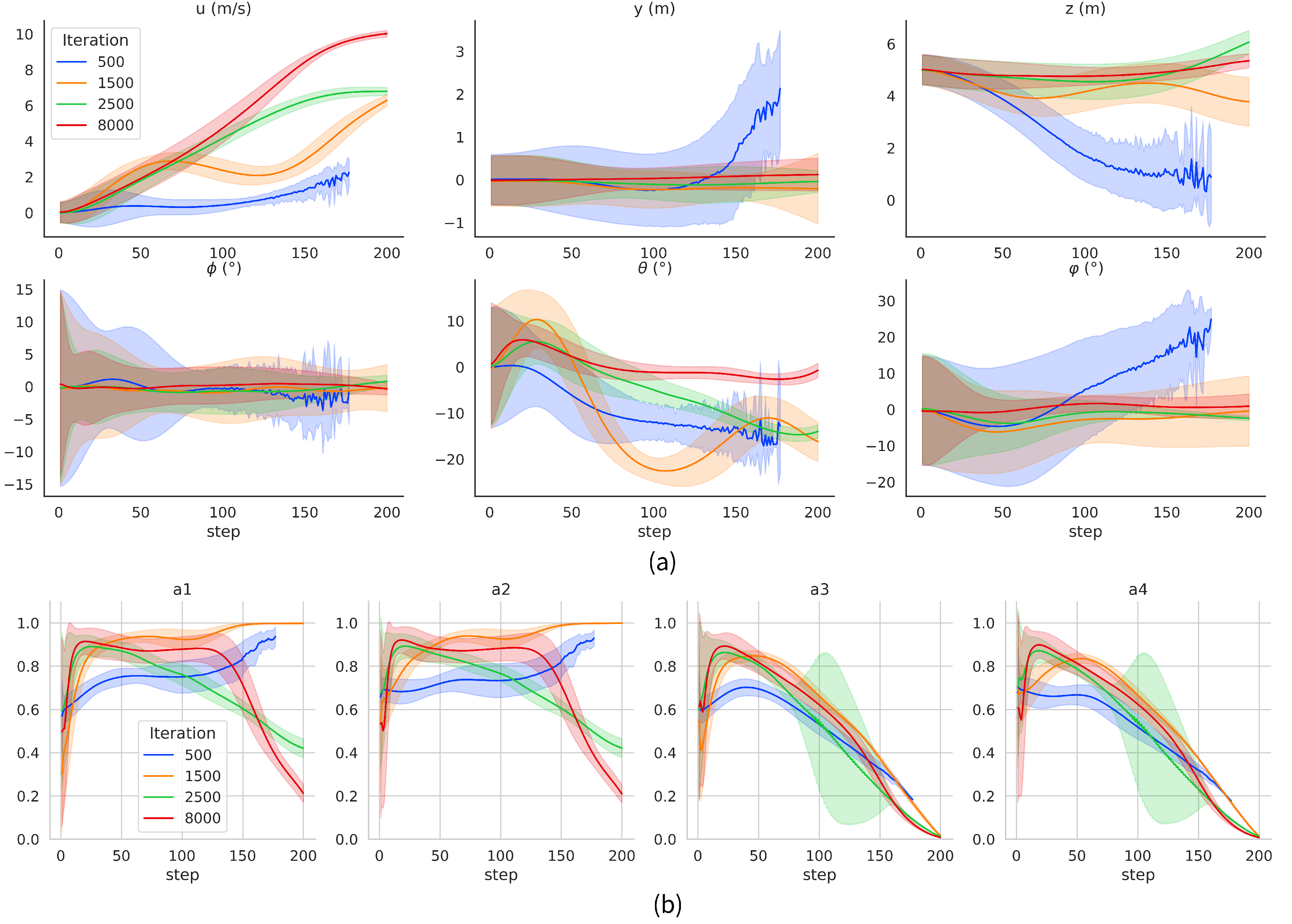
A TRUAV simulation flight test is performed by applying the neural network parameters under different iterations with the same random initial state range of the TRUAV in
Table 2 as in the training phase. To avoid losing generality, the simulation experiment was carried out 1000 times. The test results are shown in
Figure 6.
Vx(
m/
s) is the x-axis speed of the TRUAV during the transition process.
Py(
m) and
Pz(
m) are the y-axis and z-axis positions of the TRUAV, respectively.
euler_x(°),
euler_y(°) and
euler_z(°) are the roll, pitch and yaw angle of the TRUAV, respectively. In
Figure 6b, these are the outputs of the RL controller
a(
a1,
a2,
a3,
a4).
The agent cannot complete the transition when the network is trained in 500 iterations, because it could fall at about 150 steps. After 1500 iterations, the TRUAV can complete the transition process and have a forward flight speed. However, the attitude control ability for roll and yaw is poor. In particular, the pitch angle changes greatly during the transition. The attitude angles have a large deviation from the desired values at the end of the transition process. And the motor throttle amounts of a1 and a2 are larger in 50 to 200 steps. After 2500 iterations, the attitude control effect is improved, especially the control effect of the pitch angle. The motor throttle amounts of a1 and a2 are improved. However, the a3 and a4 motor throttle amount oscillate more in 150 to 200 steps. After 8000 iterations, the performance of the attitude controller is improved significantly, especially the control effect of the pitch angle. The attitude angle is around the desired value, at the end of the transition process. And it can be observed from the action output that the RL controller consumes less energy during the transition.
4.2. Reward Function Improvements
In this paper, the reward function is modified to make it suitable for TRUAV transition process strategy learning. At the same time, the reward function is improved. There are two main points, the first point is to reduce the controller output jitter by adding the deviation from the previous time output into the reward function as a consideration. Another point is to reduce the deviation between attitude angles and desired values at the end of the transition process.
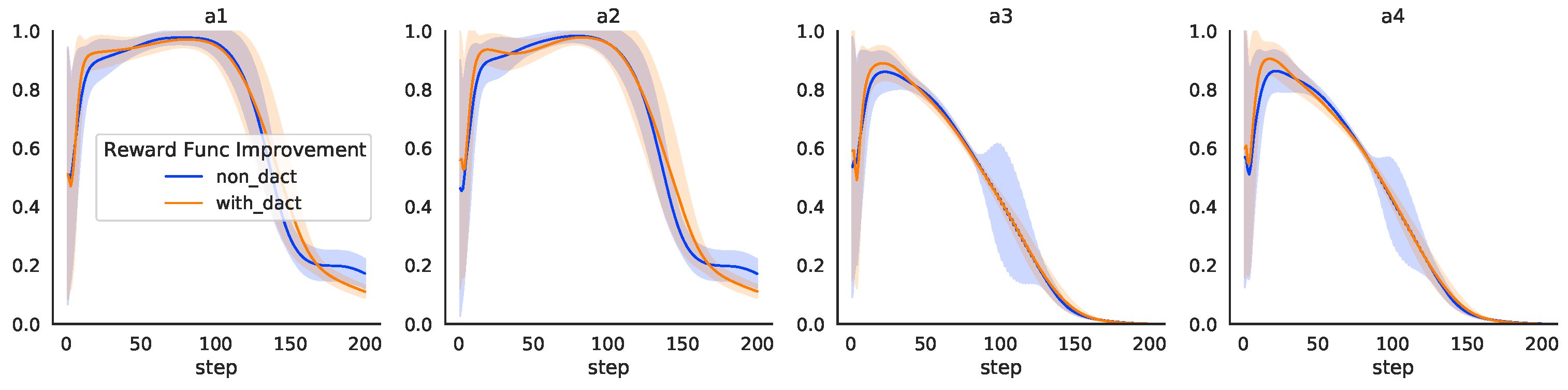
4.2.1. The Controller Output Jitter
This case compares the RL controller while training with or without the jitter cost
in the reward function. The test results are shown in
Figure 7. The improved reward function results in lower output and a narrower variance band at the end of the transition process for the front motors
a1 and
a2. The RL controller outputs of the rear two motors
a3 and
a4 have a narrower variance band and significantly less oscillation in output at 100–150 steps. The improved reward function proposed in this paper has a narrower variance band, which can reduce the controller output jitter, especially for the output of the rear motors.
4.2.2. Attitude Angle Deviation from Desired Values
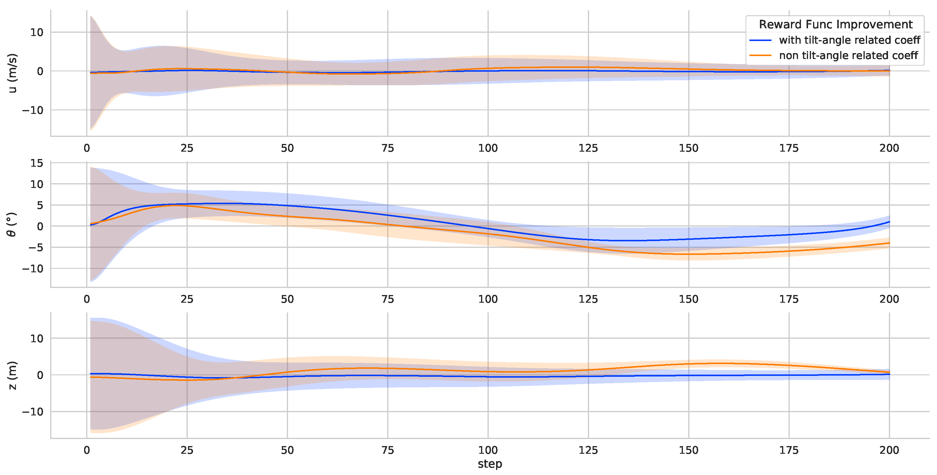
This paper proposes a coefficient related to the tilt angle of attitude angle deviation. In the reward function, the attitude angle deviation term
is multiplied by a gain that varies according to the rotor tilt angle. And it is used to reduce the deviation between attitude angles and desired values at the end of the process. The test results are shown in
Figure 8. The TRUAV roll and yaw deviation from desired values are significantly reduced at the end of the transition process. Attitude considerations differ during the transition process. The transition process is very aerodynamically complex while the TRUAV accelerates from hover to cruise speed. Because the attitude angle changes and affects the angle of attack, the end of the transition process requires more attitude stability.
4.3. Adaptability Test
To verify the adaptability and generalization of the RL controller trained in this paper, three simulations are performed. Two of them are to change the configuration of the TRUAV, take-off weight and diagonal wheelbase; the other is to change the rotor tilt rate during the transition process, i.e., the transition strategy.
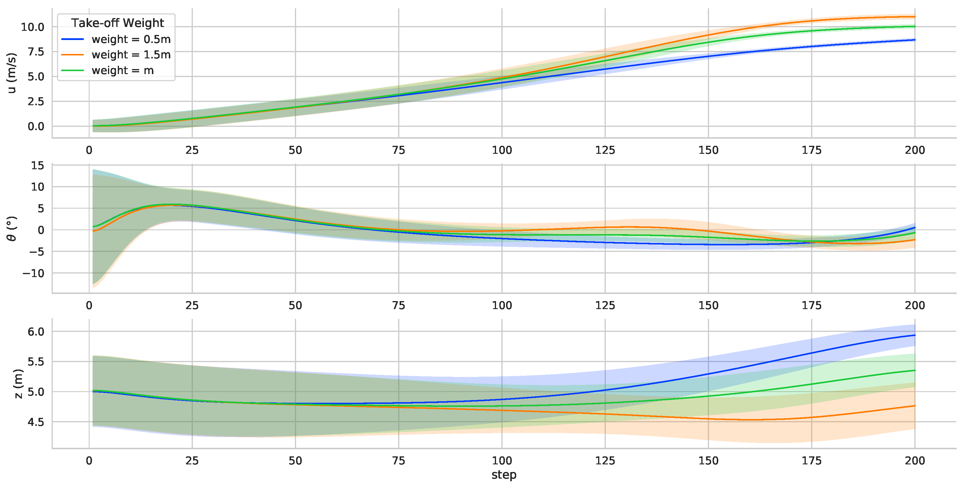
4.3.1. Take-Off Weight Test
An enormous take-off weight means that more aerodynamic lift is required to maintain altitude. Different takeoff weights simulate the transition process under different operating conditions.
Figure 9 shows that the controller can adapt to the take-off weight change using the trained neural network controller parameters. The RL controller completes the transition process by adjusting the speed and pitch to maintain the flight altitude. In the simulation environment, the adaptability of the TRUAV neural network controller was verified in varying take-off weights. There is no need to adjust the parameters, and the controller proposed in this paper can adapt to different takeoff weights.
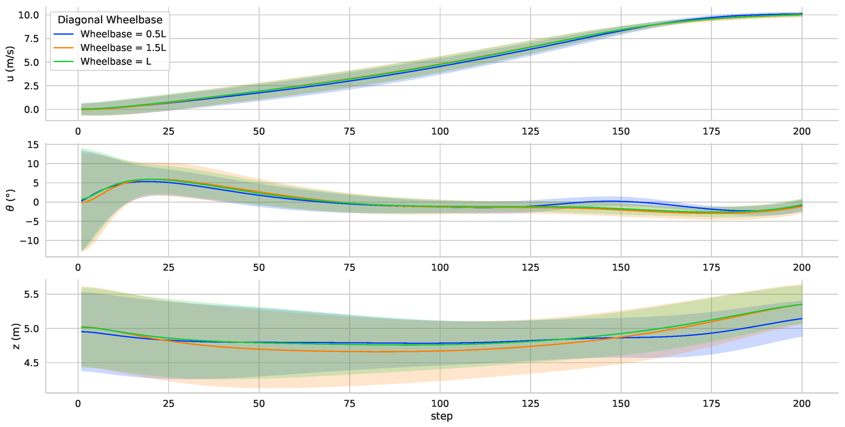
4.3.2. Diagonal Wheelbase Test
The simulation results are shown in
Figure 10. There is a small change in the flight speed, pitch angle and altitude curves. Changes in the wheelbase directly affect the torque for attitude control.
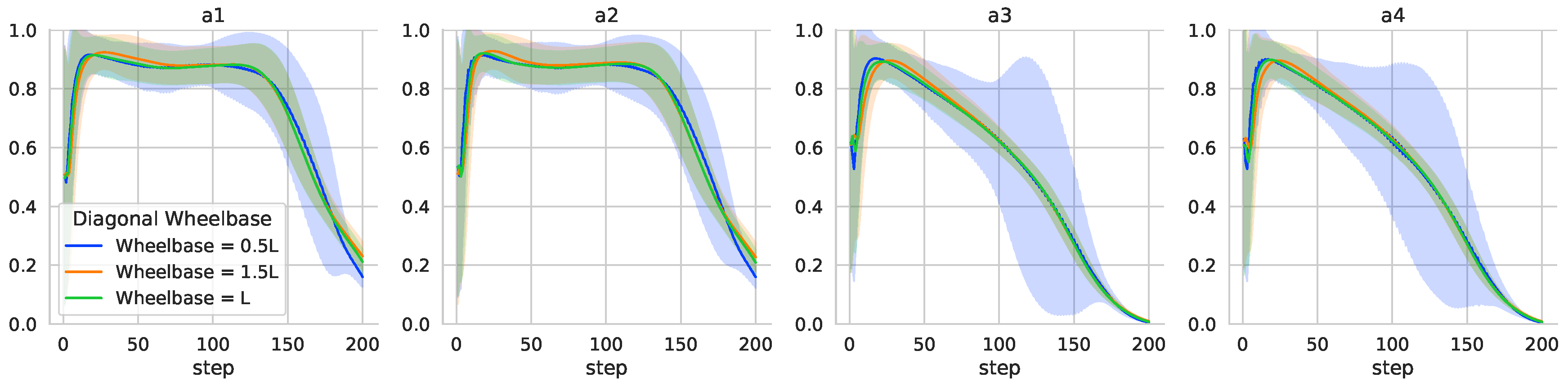
When the wheelbase changes, it is a significant challenge to the controller for attitude control. From
Figure 11, it can be found that decreasing the wheelbase has a more significant impact on the attitude control of the vehicle. The wheelbase decrease, and the motor throttle volume output jitters more. Such jitter may affect the TRUAV attitude control when subjected to external perturbations in practice. The adaptability of the neural network controller is verified by changing the diagonal wheelbase of the vehicle. In the actual application, if the diagonal wheelbase of the TRUAV changes, the actual flight data should be collected or the expert data should be used to update the neural network parameters.
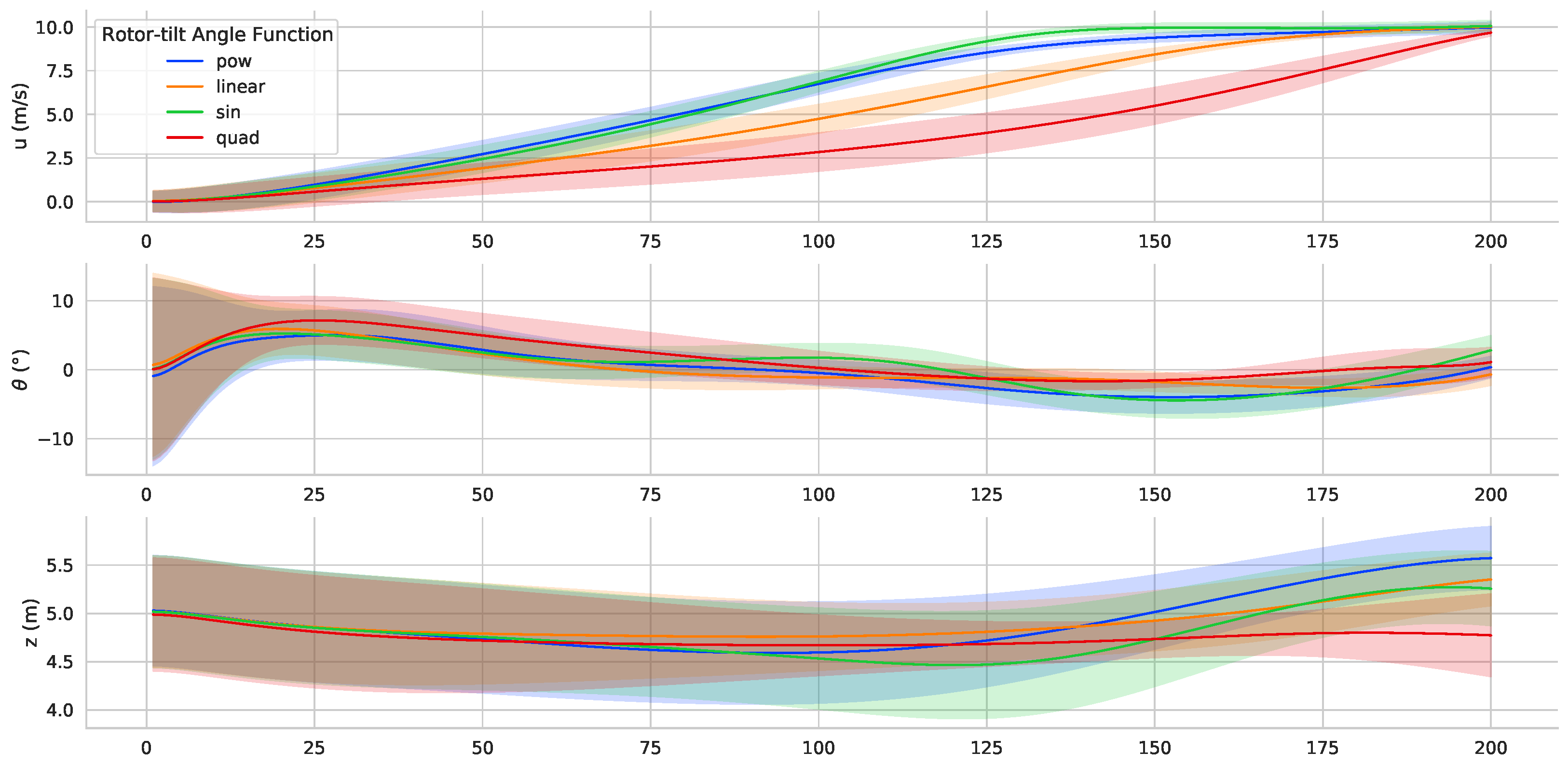
4.3.3. Rotor Tilt Angle Rate Test
The tilt angle is an important parameter in the TRUAV dynamic model. The change in the tilt angle rate directly affects the dynamic performance of the UAV. This variation affects the acceleration and flight attitude during the transition process. During RL controller training, the rotor tilt angle changes linearly. Three different tilt angle rate functions are selected to verify the adaptability of the RL controller, as shown below.
The controller is tested by varying the rotor tilt angle rate during the transition process. And the simulation results are shown in
Figure 12. At different tilt rates, the desired speed can be achieved. And less attitude deviation between attitude angles and desired values can be achieved after the transition process. Results show that, under the condition of changing the tilt angle rate, the proposed controller can control the attitude of the TRUAV and has strong adaptability.
4.4. Performance
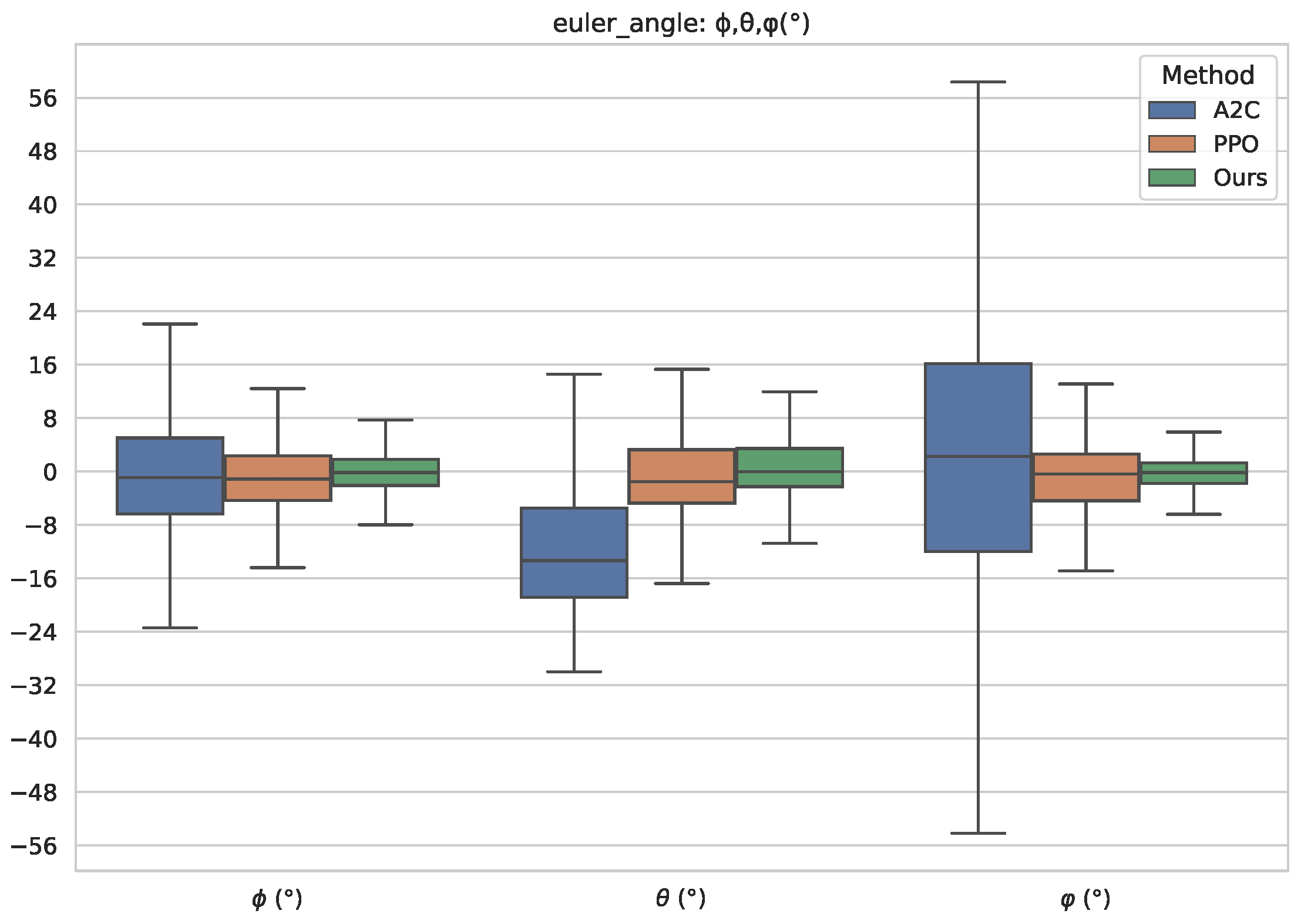
We compare our method with the standard PPO and the A2C algorithms in this case. The difference between standard PPO and the method proposed in this paper lies in the improvement of the reward function. The A2C algorithm involved in the comparison uses the same reward function and learning hyperparameters as the method proposed in this paper. In particular, we compare the control performance of the three algorithms for attitude control. To avoid losing generality, each algorithm completes the transition process under the same random initial conditions in
Table 2, and 1000 simulations are performed separately. The Euler angle of the TRUAV at the end of the transition process is collected and the simulation results are shown in
Figure 13. From the figure, we can see that the standard PPO algorithm and the proposed method have better performance for the TRUAV attitude control during the transition process. However, under the same reward function and learning hyperparameters in
Table 3, the A2C algorithm does not learn the attitude control of the transition process. At the end of the transition process, the TRUAV has a large pitch angle, and the TRUAV flies at a large angle of attack after the end of the tilt process. At the same time, the deviation of the roll angle and yaw angle from the desired value is large.
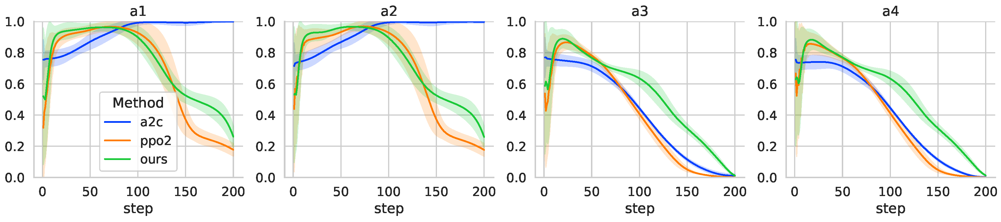
The energy consumption in the transition attitude control is also an important performance, as shown in
Figure 14. It is found that the A2C algorithm consumes more energy in controlling attitude during the tilt-rotor transition process. The A2C controller outputs of the first two motors are almost in the state of maximum speed after 100 simulation steps, which further confirms that the TRUAV is flying at a large angle of attack at the end of the transition process. The results show that, although the RL controller obtained by A2C learning can complete the rotor tilt, it is in the high angle of attack flight state and cannot control the attitude well to reach the desired values.
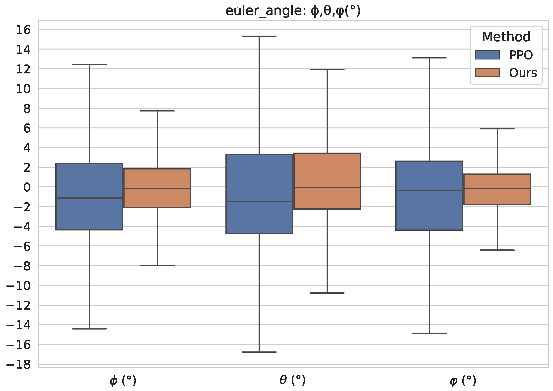
In
Figure 15, we separately compare our method with the standard PPO algorithm. And it can be seen that our proposed method improves the attitude control performance of the TRUAV transition process significantly, which effectively reduces the deviation between attitude angles and desired values. In general, compared with the standard PPO algorithm, our proposed method has a higher performance in a deviation between attitude angles and desired values while consuming more energy in the second half of the transition process.


