Article

UAV Localization in Low-Altitude GNSS-Denied Environments Based on POI and Store Signage Text Matching in UAV Images

1
School of Artificial Intelligence, Xidian University, Xi’an 710071, China
2
CETC Key Laboratory of Aerospace Information Applications, Shijiazhuang 050081, China
*
Author to whom correspondence should be addressed.
Drones 2023, 7(7), 451; https://doi.org/10.3390/drones7070451
Submission received: 26 May 2023 / Revised: 5 July 2023 / Accepted: 5 July 2023 / Published: 6 July 2023

Abstract

:
Localization is the most important basic information for unmanned aerial vehicles (UAV) during their missions. Currently, most UAVs use GNSS to calculate their own position. However, when faced with complex electromagnetic interference situations or multipath effects within cities, GNSS signals can be interfered with, resulting in reduced positioning accuracy or even complete unavailability. To avoid this situation, this paper proposes an autonomous UAV localization method for low-altitude urban scenarios based on POI and store signage text matching (LPS) in UAV images. The text information of the store signage is first extracted from the UAV images and then matched with the name of the POI data. Finally, the scene location of the UAV images is determined using multiple POIs jointly. Multiple corner points of the store signage in a single image are used as control points to the UAV position. As verified by real flight data, our method can achieve stable UAV autonomous localization with a positioning error of around 13 m without knowing the exact initial position of the UAV at take-off. The positioning effect is better than that of ORB-SLAM2 in long-distance flight, and the positioning error is not affected by text recognition accuracy and does not accumulate with flight time and distance. Combined with an inertial navigation system, it may be able to maintain high-accuracy positioning for UAVs for a long time and can be used as an alternative to GNSS in ultra-low-altitude urban environments.

1. Introduction

Unmanned aerial vehicles (UAV) have been widely used in the military [1], search and rescue [2] and mapping [3] due to their low cost and high flexibility. Highly accurate positioning information is the basis for subsequent UAV decision control during mission execution. The most basic and commonly used localization method for UAVs is the GNSS-INS system, which is composed of a Global Navigation Satellite System (GNSS) receiver, accelerometers, gyroscopes and magnetometers. In an open field, the GNSS signal is generally normal. However, in the case of urban buildings’ obstruction, the multipath effect formed by the multiple scattering of electromagnetic signals significantly reduces the positioning accuracy of the GNSS, and the positioning error can reach tens or even hundreds of meters [4]. In the case of electromagnetic interference, the GNSS signal produces severe attenuation, and the positioning error increases significantly and may even be untrustworthy. Therefore, it is important to study the autonomous localization of UAVs in an intra-city GNSS-denied environment.
Research on UAV localization under GNSS signal-denied conditions has been quite extensive, and the mainstream UAV autonomous localization scheme used as an alternative to the GNSS-INS framework is currently vision-based localization. Vision-based UAV autonomous localization methods can be classified into two categories according to whether they can directly give the absolute position of the UAV: relative vision localization and absolute vision localization [5]. Relative vision localization is mainly applied indoors, whereas absolute vision localization is more suitable for high-altitude scenarios. Open, low-altitude urban scenes have an exceptionally complex ground surface, and the scale difference between UAV images and satellite images is too large to match. Neither method enables autonomous localization for low-altitude UAVs in urban scenes.
To achieve localization for low-altitude scenes in urban areas, we present a UAV absolute visual localization method based on Point of Interest (POI) and store signage text matching (LPS). POI data are navigation-level data from electronic map software that comprise name, latitude and longitude information and that correspond to information from, for example, the signage of stores in the city. By identifying text on signages from the UAV image and matching it with entries in the POI database, the exact location of a UAV image scene can be determined; then, the 3D coordinates of the corner points of the signage are used as control points to the location of the UAV. Finally, the effect of this method is verified by the actual flight data. LPS does not require the precise location of the UAV at the moment of take-off; moreover, the positioning error does not accumulate with flight distance and flight time because the position solving process of LPS is unrelated among different images. Compared with existing methods, LPS is not limited by lighting and scale differences. LPS can provide an accurate location for UAVs in low-altitude GNSS-denied environments within cities.
The remainder of this paper is structured as follows: Section 2 describes existing works. In Section 3, the LPS framework is introduced, POI data are presented, and UAV image text recognition, text fuzzy matching, UAV image scene localization and location-solving processes are described in detail. Section 4 describes the hardware platform, data acquisition and processing processes used in the real flight verification experiments, and then the verification results of the LPS and the experimental results of its comparison with ORB-SLAM2 are presented. Section 5 discusses the factors that introduce errors in the LPS. Finally, our conclusions are given in Section 6.

2. Related Work

Relative vision localization
Simultaneous Localization and Mapping (SLAM) is a typical relative visual localization method with visual odometry (VO) as a localization principle. According to whether it is combined with an Inertial Measurement Unit (IMU) or not, it can be divided into visual SLAM and visual inertial SLAM.
Visual SLAM estimates the positional change from multiple frames and then calculates the camera’s position after accumulating positional changes in the current environment. The first visual SLAM, Mono-SLAM, was proposed [6] in 2007; based on this method, Klein et al. proposed parallel tracking and mapping (PTAM), which uses two threads of tracking and mapping. In addition, it was the first real-time visual SLAM system based on the feature point matching method [7]. Since then, many visual SLAM systems have improved upon PTAM, among which ORB-SLAM2, proposed by Raul et al. in 2017, is the best-performing SLAM system [8] supporting monocular, binocular and RGB-D cameras. ORB-SLAM2 can compute the camera’s pose in real time and simultaneously reconstruct the surrounding environment sparsely [9]. Visual SLAM is more accurate in tracking environmental features, but it is not effective in some scenarios, such as situations involving fast motion, low textures and lighting changes [10].
Considering the poor dynamic adaptation of visual SLAM, and in order to provide scale information to VO, visual inertial SLAM has become an important research direction. Combined with the Inertial Navigation System (INS), visual inertial SLAM uses visual localization information to correct the zero bias of the IMU and reduce the cumulative error [8]. Visual inertial SLAM frameworks can be classified into two types of approaches: those based on filtering and those based on optimization. According to whether image features are added to the state vector, these two approaches can be further classified into tightly coupled (the state of the IMU and the state of the camera are merged together to jointly construct the equations of motion and the equations of observation, and then state estimation is performed) and loosely coupled (the IMU and the camera perform motion estimation separately, and then the results of the positional estimation are fused together) [11]. In terms of filtering-based tight-coupling methods, the MSCKF framework performs Kalman filtering updates using feature points that are observed in multiple frames within a sliding window as geometric constraints [12]. Because image features need to be added to the feature vector, the dimensionality of the system state vector is quite high; thus, it requires a larger number of computations. The filter-based loosely coupled approach avoids adding image features to the state vector but treats the image as a black box and computes the visual odometry before fusing it with the IMU data; the classical approaches include the vision and inertial fusion framework SSF [13] and the multi-sensor fusion framework MSF [14]. Optimization-based visual inertial odometry is used for UAV poses using nonlinear optimization methods, and the OKVIS and VINS-MONO frameworks are typical representatives. OKVIS uses the Harris operator to extract image corner points and BRISK to match an image as a feature descriptor at the front end; at the back end, it solves UAV poses by optimizing the nonlinear cost function composed by an image reprojection error and an IMU integration error [15]. VINS-MONO uses Harris feature point detection and KLT optical flow tracking on the front end to pre-integrate the IMU measurements between consecutive frames; at the back end, VINS-MONO optimizes the reprojection error through a sliding window method and eliminates drift using closed-loop detection for global optimization [16].
However, SLAM is not able to provide a geodetic coordinate system unless there is a landmark with a known geographic location within the scene. Furthermore, most SLAM methods have two problems: On the one hand, targets in the scene are assumed to be stationary [17], and moving targets are prevalent in urban scenes, which may lead to failure in inter-frame feature point matching. Thus, some studies have extracted feature points from stationary targets only for image matching [18,19]. On the other hand, SLAM requires closed-loop detection to correct the accumulated errors from a long flight time [8]. However, in large urban scenes, the flight trajectories of UAVs are likely not to cross, and closed-loop detection conditions are often difficult to meet.
Absolute vision localization
Absolute visual localization performs UAV localization by matching the current frame image of the UAV with a geo-referenced image, which is usually an ortho-satellite remote sensing image or a previously collected UAV image of the same area. The most commonly used image matching methods include template matching and feature point matching. The challenge of these methods is that the UAV image and the geo-referenced image differ in acquiring time, lighting conditions and observational viewpoint, which means that the features of the same target on the two images are different and may lead to further matching failures. The solution of such problems is to extract features that are not related to the acquiring time, lighting conditions or observational viewpoint.
The main template matching algorithms include the sum of squared differences (SSD), normalized cross-correlation (NCC) and phase correlation (PC), but these algorithms are sensitive to seasonal and environmental changes and are less effective when a temporal difference exists between the reference image and the UAV image is large [20,21]. To overcome these shortcomings, Yol and Patal et al. chose to use mutual information (MI) as a similarity metric to calculate scene similarity [22,23]; additionally, Pascoe et al. proposed using the normalized information distance (NID) based on MI [24]. However, both MI and the NID cannot achieve satisfying matching results when the color difference is obvious.
Image feature point matching algorithms, such as FAST, Harris and SURF feature operators, are sensitive to image differences [25,26,27]. Mantelli et al. proposed the abBRIEF operator based on the BRIEF operator, which uses the CIE image color space instead of the grayscale map and retains the advantage of fast computation and overcomes the effect of illumination differences [28]. Jouko et al. used convolutional neural networks to extract seasonal invariant features [29] while attempting to use UAV poses to produce vertical downscale images for eliminating perspective differences [30]. Wang et al. argued that shadows on an image can be used as an invariant feature for image matching, and with a known DSM, a reference shadow map can be simulated. By extracting the UAV image shadows on the image and matching them with the reference shadow map, UAV localization can be performed [31]. In addition, when faced with large scenes, the feature point matching method is computationally intensive, and the required geo-referenced images occupy a large amount of storage space, both of which limit the effect of its application to a certain extent.
Another method that can avoid the effect of acquiring time and lighting conditions on image matching is using maps as the geo-referenced data. Choi et al. used a building ratio map (BRM) as a reference image and then extracted building areas from UAV images and matched them with the BRM to achieve UAV localization [32]. Nassar et al. used a U-Net network to extract building individuals from satellite remote sensing images as a localization reference and extracted building individuals from UAV images as well; then, they used the semantic shape match (SSM) method to achieve image matching [33]. Further, Masselli et al. used the ground cover classification map as the geo-referenced data and then classified the UAV image into the same system as the ground cover classification map in real time before matching it with the geo-referenced base map [34]. The above methods can reduce the influence of illumination differences on image matching to a certain extent but still cannot solve the problem of the huge scale difference between the geo-referenced images and the UAV images when the UAV flight altitude is low, especially in urban areas with unusually complex ground cover.
In addition to the above methods, Naqqash et al. proposed a text recognition-based method for autonomous UAV localization, which is similar to our algorithm. However, it assumes that the UAV is in an Internet environment and retrieves the scene location by inputting the recognized store names into the Application Programing Interface (API) of an electronic map; moreover, this method cannot solve the UAV location [35].

3. Methods

3.1. The LPS Framework

The overall algorithm framework of LPS is shown in Figure 1. First, the acquired POI data are pre-processed, which includes invalid data cleaning, projection conversion and POI name separation, to form a POI database that can be used for UAV localization. The text information of store signage is extracted from the sequential UAV images and matched with the pre-processed POI database. When the number of successful matches between store signages and the POI is sufficient and the UAV flight distance limit is satisfied, the latitude and longitude of the store signages in the UAV image can be determined. Finally, multiple store signages in a single image are used to provide control points and solve the exact position of the UAV.

3.2. Introduction to POI

A POI usually refers to the point data in an Internet e-map, which basically contains four attributes: the name, address, coordinates (latitude and longitude) and category, and it can meet the basic needs of users to “find the destination” and then evoke navigation services. The POI data are derived from the vector dataset of point-like map elements in the digital line graphic (DLG) product of basic mapping results [36]. Currently, the POI data of the Chinese Internet e-map are leading in terms of data volume, coverage, accuracy and update frequency, and they can basically meet the demand of GIS application scenarios in different industries.
For stores that are widely distributed in a city, the text on their signage can correspond to the names of POIs, and their locations can correspond to the coordinates of POIs, as shown in Figure 2.
The importance of each word in the POI name is different. For example, the word “Beiguo” in “Beiguo Supermarket” is indicative of the location, and the word “supermarket” is widely distributed throughout the city and is not indicative of the location. Thus, the POI name is pre-phrased using python’s Chinese text segmentation component jieba for subsequent text matching.

3.3. Text Recognition in the UAV Images

In this paper, we used the PP-OCRv3 model to recognize the text in UAV images. PP-OCRv3 is an ultra-lightweight OCR system used for industrial applications that is both accurate and efficient at processing, and it was proposed by Baidu’s PaddleOCR team [37]. The PP-OCRv3 model consists of three parts: text detection, detection frame rectification and text recognition. For the text detector, PP-OCRv3 uses the RSE-FPN module to improve feature map representation; the convolution kernel is changed for path enhancement in the LK-PAN module to 9 × 9 to improve the perceptual field at each position of the feature map, thus making it easier to detect text in large fonts. In the DML module, the text detection accuracy is improved through the mutual learning of two models with the same structure. For the text recognizer, the Transformer structure is used instead of RNN to optimize the SVTR model to improve the text recognition ability, and the Mix Block structure is improved to shorten the text recognition time. In this paper, the pre-trained PP-OCRv3 model was directly used for text recognition in UAV images without more training.

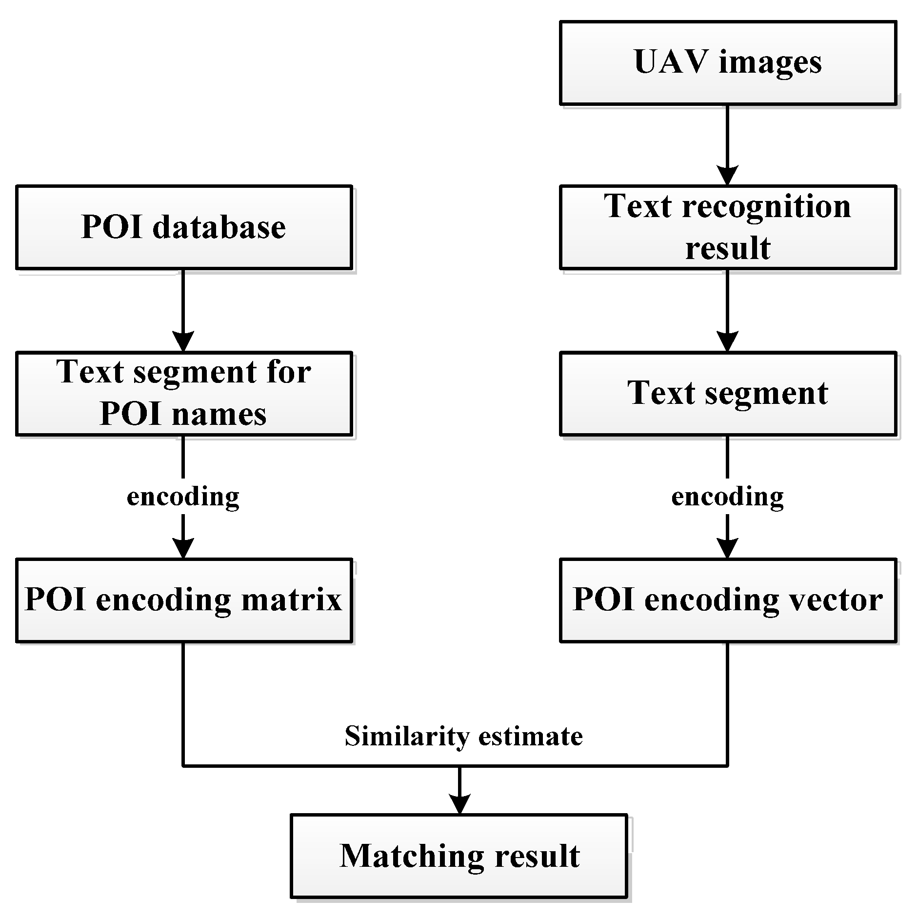
3.4. Fuzzy Matching of Store Signage Text and POI Names

Possible differences between the store signage text and its corresponding POI name, the UAV image not capturing all of the store signage text and the problem of errors in the text recognition process may lead to text matching failures that should be matched successfully. Therefore, this paper adopts the text fuzzy matching technique based on inverse document frequency (IDF) [38] to achieve the matching of the text recognized in the UAV image with the POI name, and the matching process is shown in Figure 3.
(1)
Count the number of different phrases in the name attribute of the POI database, and calculate the IDF value for each phrase with the following formula:
I D F = log 2 n c o u n t + 1
where n represents the total number of entries in the POI database and count represents the number of POI entries containing this phrase.
(2)
Encode each POI name string by generating a vector of length m. Each position of the vector represents the IDF value of a phrase, where m represents the number of all phrases contained in the POI database.
(3)
For the store signages recognized from the UAV images, first perform text segmentation, and then perform the same encoding as that in step (2).
(4)
Match the store signage text identified in the UAV image with the name in the POI database. Iterate through the POI database and use the cosine function to measure the similarity between the name in the POI database and the store signage text:
cos ( x , y ) = x y | | x | | × | | y | |
x   and   y represent the encoding vector of the POI database name to be matched and the encoding vector of the store signage text, respectively. In this paper, the text is thought to be matched successfully if the similarity exceeds 0.75.

3.5. Scene Localization for UAV Images

The prerequisite for UAV location solving using signage information is knowing the scene location of the UAV image. In other words, it must be determined which store signage in the UAV image corresponds to which entry in the POI database, and it must determine what its latitude and longitude are. Assuming that the exact location of the UAV at take-off is unknown, two processes are required to perform UAV image scene localization: (1) The first process is scene initialization localization, which uses multiple observed and matched store signages to determine the exact location of the UAV image. (2) The second process is scene update, which uses the initialized location of the scene to narrow the search space for scene localization and achieves fast scene localization. The specific process is shown in Figure 4.
(1) 
Scene initialization localization
Considering possible matching errors caused by text recognition errors due to the prevalence of stores with the same name (e.g., chain stores) and stores with similar names within a city, the text matching of a single signage does not uniquely determine which POI it corresponds to. Therefore, LPS uses an initialized localization method of UAV image scenes under the restriction of multi-POI topological relationships to determine which POI the recognized store signage corresponds to, with the following steps:
(a)
Assuming a large position uncertainty for the UAV at take-off, the POI database is spatially retrieved with the UAV take-off position as the center and the uncertainty R as the radius, and the retrieved results are used as subsequent POI entries to be matched.
(b)
Text is recognized from sequential UAV images and is pre-processed. Because some store signages are truncated by the UAV images, leaving only one word, and to ensure that the text matching process is as trustworthy as possible, any recognized text shorter than two words is removed. In addition, due to the high overlap of consecutive frames of UAV images, the text is detected repeatedly; thus, to avoid duplicate matching, duplicate text with a high similarity is removed according to the IDF model.
(c)
The recognized text is fuzzy matched with the names in the spatially retrieved POI database using the IDF model, and the match is considered successful when the similarity between the text and the names of the POI exceeds 0.75.
(d)
Because the fuzzy matching result for the text of a single signage may contain multiple POIs, and in order to ensure that the final matched POIs are correct, the distance between the matched POIs for multiple signages during scene initialization is quite strict, and the interval cannot exceed 50 m. When the cumulative number of successfully matched texts does not reach 3, the text continues to be identified from the subsequent images and is matched with the POI. When the cumulative number of successfully matched texts reaches 3, the DBSCAN algorithm is used to cluster the location of the matched POIs, and the parameter eps are set to 50 m. If there are no less than two POIs in the clustering cluster, the POIs in the cluster correspond to the signages in the UAV image. If there is no clustering cluster, the text continues to be identified and is matched with the POI from the subsequent images.
(2) 
Scene update
Once the initial location of the scene is achieved in the i-th frame, when determining the latitude and longitude of the signages in the subsequent frames (called scene update in this paper), the distance can be used to limit the matching range of the POI to improve the efficiency of signage text matching and to reduce the probability of false matching. The specific process is as follows:
(a)
Spatial retrieval of POI data is carried out with the initialized location of the scene as the center and 50 m as the radius. Then, the retrieval results are subsequent POI entries to be matched.
(b)
Text recognition occurs for the j-th frame image and removes any text shorter than two words.
(c)
Fuzzy matching of the recognized text with the names in the POI database is performed after spatial retrieval using the IDF model, which is considered successful when the similarity between the text and the name of the POI exceeds 0.75.
(d)
If the match is successful, the location of the UAV image scene at this time is the latitude and longitude of the POI corresponding to the signage. If the match is not successful, the POI spatial retrieval radius is reset to r, and then the next image frame is processed, where r = V × (j – i) + 50 m and V is the maximum flight speed of the UAV.

3.6. UAV Position Solving

Figure 5 shows an image where multiple signages are recognized and matched to the POI database. Table 1 shows the store signage text information recognized from Figure 5. The red boxes represent the store signages extracted by the PPocr-v3 algorithm. Ai, Bi, Ci and Di are the corner points of the signages, Oi is the center point of the store signage, and E is the intersection of the line O2O4 with the left side of the store signage of ID.2. To use the PnP algorithm for UAV position solving, at least four control points with 3D coordinates must be extracted from one single image. Each POI has only one latitude and longitude, which cannot provide enough control points; therefore, the image needs to contain at least two successfully matched signages to recover the scale information for calculating more control points with three-dimensional coordinates.
In this paper, we assume that the latitude and longitude of the POI represent the position of the central pixel of the signage, and then the geographical coordinates of the extracted corner points of the signage are calculated as follows:
(1)
The image coordinates of the center pixel point of the store signage Oi (Xi, Yi) are calculated. Based on the extracted image coordinates of the four corner points of each signage, the mean value of the row and column directions is calculated as follows:
X i = j = 1 4 x i j Y i = j = 1 4 y i j
where i represents the ID of the store signage and j represents the corner point serial number of the store signage.
(2)
Store signages at the same height in the image are found. Because of the roll angle when taking UAV images, the store signages at the same height may actually not be located in the same row in the image. To determine whether the store signage of ID.1 and the store signage of ID.2 in Table 1 are at the same height, a straight line is formed by connecting the midpoint of A1D1 and the midpoint of B1C1. If this line passes through the rectangle formed by the corner points of the store signage of ID.2, these two signages are considered to be at the same height; otherwise, they are not at the same height. By iterating all signage combinations, store signages at the same height can be identified.
(3)
If only one shop signage exists at different heights, then this image is skipped. In addition, if there is more than one store signage at the same height in step (2), the signages at the lowest level are chosen to calculate the latitude and longitude coordinates of the corner points. If there are more than two store signages at the lowest level, the two signages at the farthest distance are chosen to calculate the latitude and longitude of the corner points. Therefore, in Figure 5, the signage of ID.2 and signage of ID.4 are chosen to calculate the latitude and longitude of the corner points. The latitude and longitude of two corner points on the same side of the same store signage are the same, and only the height is not the same (such as for point A2 and D2 in Figure 5). For point E in Figure 5, it has the same latitude and longitude as those of A2 and D2; therefore,
O 2 E = α O 2 O 4
where α is the scale factor. Equation (4) represents both the image pixel distance relationship and the actual Euclidean space distance relationship, and the image coordinates of point E have the following relationship:
α = O 2 E O 2 O 4 ( y 21 + y 24 ) / 2 Y 2 Y 4 Y 2
Therefore, the geographic coordinates of point E are related as follows:
l o n 2 l o n E l o n 4 l o n 2 = l a t 2 l a t E l a t 4 l a t 2 = α
Then,
l o n E = l o n 2 α ( l o n 4 l o n 2 ) l a t E = l a t 2 α ( l a t 4 l a t 2 )
Therefore, the geographical coordinates of points A2 and D2 are ( l o n E , l a t E ) . Similarly, the latitude and longitude of control points B2, C2, A4, B4, C4 and D4 can be calculated.
To obtain the height of the control points, simulation experiments are conducted (see Section 5). The simulation results show that the absolute height of the store signage does not affect the UAV plane positioning accuracy, and the width of the signage has less influence on the UAV positioning. Thus, we only use the signage located at the same height to select the control points. In addition, the height of the lower corner points of the signage is set to 3 m, and the height of the upper corner points is set to 4 m.
Considering that the number of control points is usually not less than 8, the direct linear transform (DLT) solution method of PnP was adopted to solve for the UAV position.

4. Experiments and Results

4.1. Experiment Data

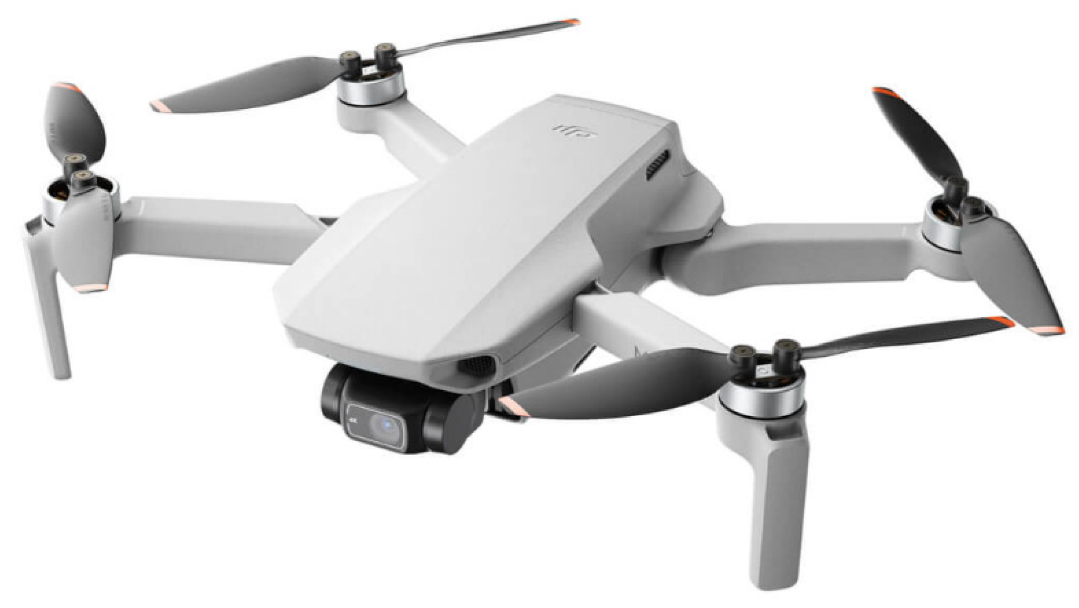
4.1.1. Hardware Configuration

Considering intra-city flight safety, we used the DJI mini2 as the UAV platform, as shown in Figure 6, which weighs just less than 250 g and has a volume of 159 × 203 × 56 mm (in the case of wing expansion). The maximum flight speed of the mini2 is 4 m/s.
This UAV uses GPS for positioning. Its horizontal positioning accuracy is ±1.5 m, and its vertical positioning accuracy is ±0.5 m, enabling it to record the real flight path. The image size is 4000 × 2250 pixels. During the flight, the three-axis gimbal controls the camera’s side-view imaging. Using the timed shooting mode, imaging shots were taken at 2 s intervals. The focal length is 24 mm, and the field of view is 83°. The tessellation calibration method was used to obtain the intrinsic matrix and distortion parameters of the camera [39], and the intrinsic matrix K and distortion matrix D are as follows:
K = 3051.98 0 2012.25 0 3050.75 1115.57 0 0 1
D = 0.0579 1.1885 0.0000566 0.00412 5.7547

4.1.2. Data Acquisition

The experimental area was two streets within the city of Shijiazhuang, Hebei Province, China. The first street was Chengjiao Street, with a flight distance of about 560 m (Figure 7); the second street was La Street, with a flight distance of about 550 m (Figure 8). The flight height was between about 30 m and 50 m, and the shooting angle aligned with the store signage.

4.1.3. POI Data

Due to the unavailability of high-precision open-source POI data, we used POI data collected by a surveying and mapping company; the data were collected during 2018–2021. After comparing these data with the latest POI data from Gaode Map (an electronic map navigation software), it was determined that less than about 40% of the POI in Chengjiao Street and La Street has changed due to urban renewal and that the relative positions of the POI that have not changed are basically consistent with those of Gaode Map.
The POI data cover the area of Shijiazhuang city with the GCJ-02 coordinate system, which is a coordinate system obtained by offsetting the WGS84 coordinates [40]. Therefore, the POI data were reprojected to the WGS84 geographic coordinate system using the open-source software GRASS GIS (Geographic Resources Analysis Support System) software before they were used.
In order to improve the efficiency of text matching, the entries in the POI whose type belongs to a bus station and parking lot were cleaned out, because they could not be text matched.

4.2. Results

4.2.1. Text Recognition Results

The text recognition results for the UAV images are shown in Figure 9. In order to enable people to read them easily, almost all of the store signages use a normal font. Thus, almost all of the text shown in the images is recognized correctly, and only a few mistakes occur. For example, in Figure 9(1), all Chinese words are correctly recognized, but one store icon is incorrectly recognized as characters. In Figure 9(2), some words are blocked by the rain shelter, and these words are not all displayed in the image. Thus, they are not recognized. In addition, a few words are missed.
Because the text matching process uses fuzzy matching and the scene localization process relies on multiple POIs, a small number of text recognition mistakes and misidentifications do not impact the final scene localization and UAV location solving.

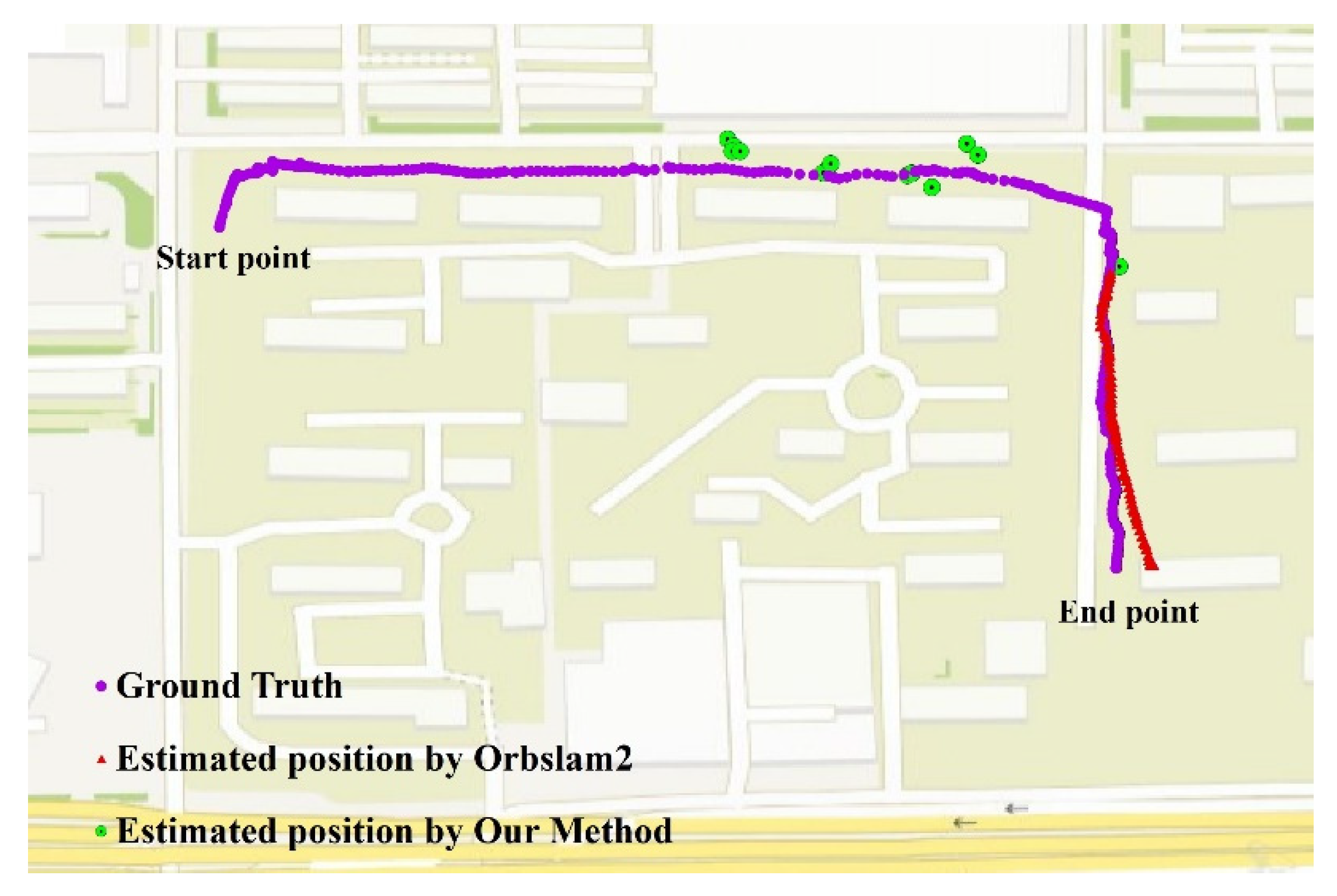
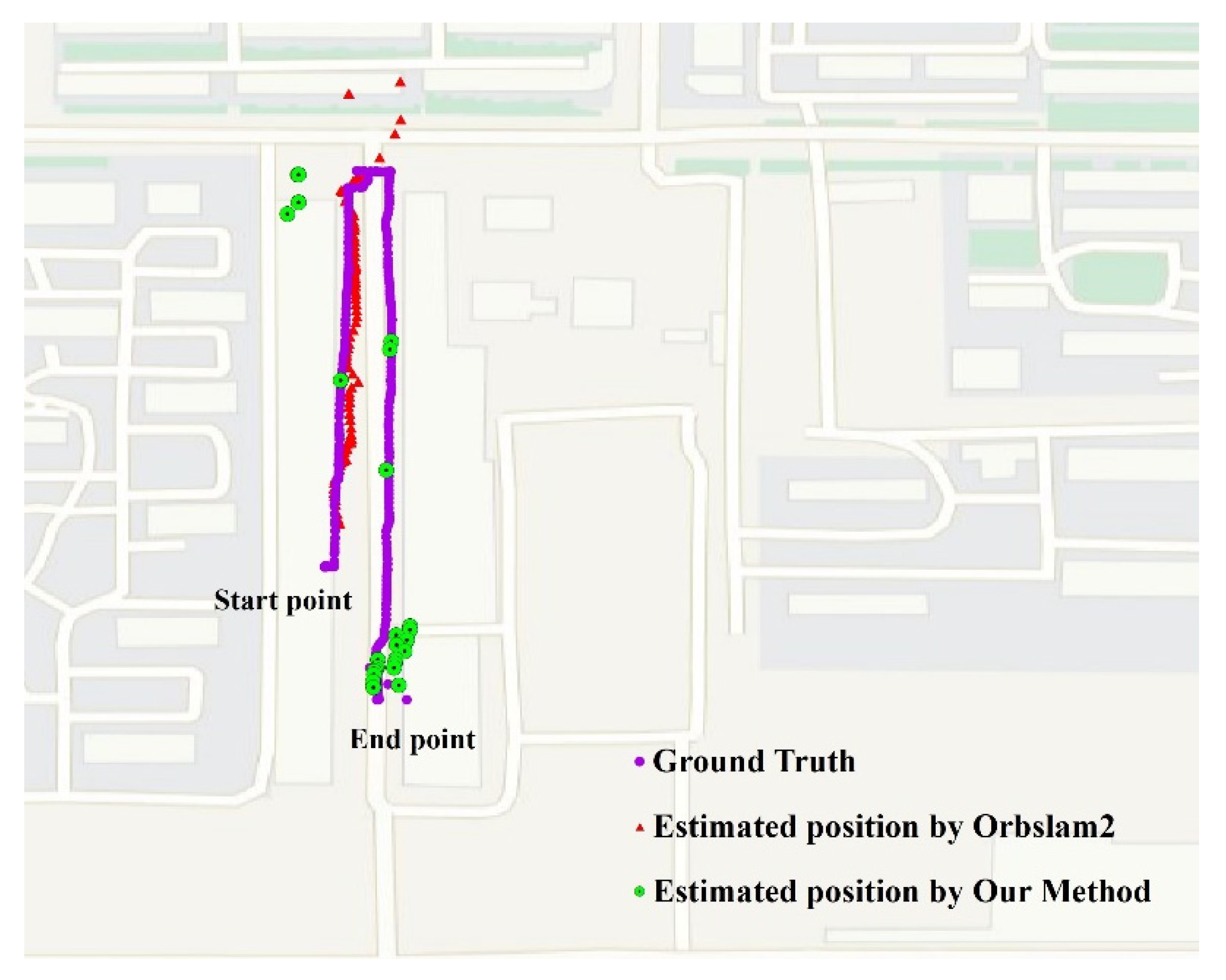
4.2.2. UAV Positioning Results

To analyze the effect of the LPS algorithm, ORB-SLAM2 is used as the comparison algorithm. In order to improve the operation efficiency of ORB-SLAM2, the UAV images were resampled to 1200 × 675; in order to recover the scale information of ORB-SLAM2, the real latitude and longitude of the UAV in the first 10 frames were used to construct the conversion relationship between the SLAM coordinate system and the geographic coordinate system. When ORB-SLAM2 experienced a tracking failure, the coordinate conversion relationship was calculated again. The results from ORB-SLAM2 and the method presented in this paper are shown in Figure 7 and Figure 8. The purple dots are the real flight trajectories acquired by UAV GPS, the red triangles are the tracking results of ORB-SLAM2 (only the longest tracking trajectories in each data segment are shown), and the green dots are the UAV positioning results of the LPS algorithm.
In the first-flight data presented in Figure 7, the LPS method achieved UAV positioning in a total of 11 positions with an average positioning error of 13.22 m and a standard deviation of 4.69 m. Moreover, ORB-SLAM2 failed during position tracking at multiple moments and produced an accumulation error as the UAV flight distance increased, and in the last 152 m of flight, the positioning error of ORB-SLAM2 reached 14.84 m.
In the second-flight data presented in Figure 8, the LPS method achieved UAV positioning in a total of 24 positions with an average positioning error of 13.47 m and a standard deviation of 7.72 m. The positioning error was independent of the motion duration and motion distance. ORB-SLAM2 performed better when the UAV was moving in a straight line and estimated the UAV position more stably with an average positioning error of only 4.58 m. However, when the UAV made a large-angle turn at some point in the middle, the positioning error rapidly increased to about 50 m, which was followed by a tracking failure.

5. Discussion

5.1. Analysis of Localization Error

There are two main elements affecting the positioning accuracy of the UAV in the LPS algorithm. One is the positioning error of the POI itself, and the other is the absolute height uncertainty of the store signage.
POIs are navigation-level data, and their purpose is to be used for map navigation services; therefore, its coordinates do not correspond to the center point of the signage strictly. To estimate the error of the POI data, we used GPS-RTK to collect the real latitude and longitude of the store signage in the field, and the results show that the average positioning error of the POI data is about 5.5 m. To evaluate the impact of the POI positioning error on the UAV localization error, we conducted the following simulation experiments: Assuming that the latitude, longitude, width and height of the center points of two store signages in a single image are known, by calculating the latitude, longitude and height of the corner points of the signages, the true value of the UAV position can finally be solved; then, a horizontal random perturbation of −5~5 m is added to the latitude and longitude of the center points of these two store signages, and the UAV position is solved again. Finally, the error of UAV localization can be calculated. This process was repeated 1000 times, and the results are shown in Figure 10a. The average positioning error of the UAV is 6.7 m. Therefore, the accuracy of the POI has a relatively large impact on solving the UAV position.
The absolute height of the corner points for the store signage is determined by the height of the center point of the store signage and the width of the store signage. To evaluate the influence of the corner points’ height on the UAV localization accuracy, we assumed that the latitude, longitude, width and height of two store signages in a single image are known, and we conducted the following simulation experiments: (1) We calculated the latitude, longitude and height of the corner points of the signages to solve for the true value of the UAV position; then, we added a random perturbation of −0.5~0.5 m to the height of the store signages to solve for the UAV position again; we calculated the error and repeated this process 1000 times. (2) We added a random perturbation of −0.5~0.5 m to the width of the store signage (most of the store signages in the city have a width of about 1 m, and the size is relatively fixed), solved for the UAV position again, calculated the error and repeated this process 1000 times. The results are shown in Figure 10b,c. The absolute height of the center point of the store signage has no effect on the horizontal positioning accuracy of the UAV. This is because the height change in the store signage is only equivalent to the translation in the vertical plane for the UAV localization. When the width error of the store signage is within 0.5 m, the average positioning error of the UAV is only 0.19 m, so the width error of the store signage has a very small impact on the plane positioning accuracy of the UAV.
In addition, the distribution and number of store signages used for UAV location solving may also affect the accuracy. As more store signages are used for UAV location solving, the error tends to be smaller, and as more distant store signages are used for UAV location solving, the error also tends to be smaller.

5.2. Analysis of the Number of Localization Points

The POI data used in this paper are relatively old; the POI were collected during 2018–2021, and the UAV images were captured in early 2023. Considering that some POIs changed with urban renewal, the scenes photographed by the UAV were not exactly the same as those recorded by the POI. However, incorrect POIs are not successfully matched to signage text in the image, so they do not result in incorrect scene localization but only reduce the number of localization points. If we can obtain POI data with better timeliness, such as the POI data from Gaode Map (a Chinese e-map software), the number of localization points for the UAV should be greater.
Moreover, some store signages were obscured by rain shelters, so only about 40% of the store signages could be accurately identified and matched. Given that UAV location solving requires no less than two store signages in a single image, the number of localization points for the UAV is actually even less.
When a few words in the signage are incorrectly recognized, fuzzy matching may still be able to match correctly, at which point the text recognition error does not affect the localization process; when fuzzy matching fails because multiple words in the signage are incorrectly recognized or missed, this may result in the further failing of scene localization. In general, the text recognition error may reduce potential localization points, but it has no effect on the UAV positioning error.

6. Conclusions

In this paper, we proposed a low-altitude UAV localization algorithm named LPS based on POI and store signage text matching, which achieves UAV localization by recognizing the text of store signages in the images captured in real time during flight and matching them with the names in the POI database under the spatial distance limitation. Ultimately, the UAV location can be determined using the latitude and longitude information of multiple store signages in a single frame of the image. Unlike traditional visual localization algorithms, LPS does not require an accurate initial UAV location (or even just advanced knowledge of the city where the UAV is located), and the UAV localization processes do not generate cumulative errors. Although the LPS algorithm relies on the text recognition algorithm, the text recognition accuracy has no impact on the UAV localization error but may only reduce the potential localization points.
Real flight experiments were conducted in Shijiazhuang, China, and the errors were compared with the real UAV GPS data as well as data from ORB-SLAM2. The LPS achieved an average error of 14.84 m and 13.47 m for the two segments of data at different flight distances, and the positioning error did not increase with the UAV flight distance and flight duration. Moreover, ORB-SLAM2 showed error accumulation and tracking failure in both of its flight experiments. The comparison experiments show that the LPS algorithm has stability without divergence and is not easily interrupted, and the localization accuracy is better than that of ORB-SLAM2 in long-distance flight within the city.
However, there are still some limitations to this study. Considering that the LPS algorithm uses store signage to achieve UAV localization, there are certain requirements for UAV flight height which are not always satisfied. When the flight height exceeds 50 m, the text is seriously distorted due to a large side-view angle, and the text recognition accuracy may be seriously reduced, at which time the LPS algorithm may fail. In addition, in the area where the stores are sparse or the signages are sheltered by trees or other things, the UAV localization points may be sparse, and at this time, the assistance of other localization means may still be needed.
In the future, if high-precision map technology is more perfectly developed and more high-precision POI data can be obtained, the LPS algorithm can achieve better accuracy.

Author Contributions

Conceptualization, H.G., G.W. and Y.L.; methodology, Y.L., X.W., F.S. and Z.G.; error analysis, F.S.; writing—original draft preparation, Y.L.; writing—review and editing, J.B.; software, Y.L., X.W. and F.S. All authors have read and agreed to the published version of the manuscript.

Funding

This research was supported by the National Natural Science Foundation of China under grant U22B2011, U20B2064 and 62276206, and the Key Research and Development Program of Shannxi under grant 2022GY-062.

Informed Consent Statement

Not applicable.

Data Availability Statement

Not applicable.

Acknowledgments

The ORM-SLAM2 experiments were supported by Chenyang Li and Junzhi Guan.

Conflicts of Interest

The authors declare no conflict of interest.

References

  1. Li, N.; Xiang, W. Summary of Research Status of UAV Combat Navigation and Positioning in Urban Environment. Unmanned Syst. Technol. 2022, 5, 75–87. [Google Scholar] [CrossRef]
  2. Scherer, J.; Yahyanejad, S.; Hayat, S.; Yanmaz, E.; Vukadinovic, V.; Andre, T.; Bettstetter, C.; Rinner, B.; Khan, A.; Hellwagner, H. An Autonomous Multi-UAV System for Search and Rescue. In Proceedings of the 2015 Workshop on Micro Aerial Vehicle Networks, Systems, and Applications for Civilian Use; Florence, Italy, 18 May 2015; Association for Computing Machinery, Inc.: New York, NY, USA, 2015; pp. 33–38. [Google Scholar]
  3. Gonçalves, J.A.; Henriques, R. UAV Photogrammetry for Topographic Monitoring of Coastal Areas. ISPRS J. Photogramm. Remote Sens. 2015, 104, 101–111. [Google Scholar] [CrossRef]
  4. Jiang, Z.; Groves, P.D. NLOS GPS Signal Detection Using a Dual-Polarisation Antenna. GPS Solut. 2014, 18, 15–26. [Google Scholar] [CrossRef]
  5. Couturier, A.; Akhloufi, M.A. A Review on Absolute Visual Localization for UAV. Robot. Auton. Syst. 2021, 135, 103666. [Google Scholar] [CrossRef]
  6. Davison, A.J.; Reid, I.D.; Molton, N.D.; Stasse, O. MonoSLAM: Real-Time Single Camera SLAM. IEEE Trans. Pattern Anal. Mach. Intell. 2007, 29, 1052–1067. [Google Scholar] [CrossRef]
  7. Klein, G.; Murray, D. Parallel Tracking and Mapping for Small AR Workspaces. In Proceedings of the 6th IEEE and ACM International Symposium on Mixed and Augmented Reality, Washington, DC, USA, 13–16 November 2007. [Google Scholar]
  8. Macario Barros, A.; Michel, M.; Moline, Y.; Corre, G.; Carrel, F. A Comprehensive Survey of Visual SLAM Algorithms. Robotics 2022, 11, 24. [Google Scholar] [CrossRef]
  9. Mur-Artal, R.; Tardos, J.D. ORB-SLAM2: An Open-Source SLAM System for Monocular, Stereo, and RGB-D Cameras. IEEE Trans. Robot. 2017, 33, 1255–1262. [Google Scholar] [CrossRef]
  10. Qinghua, Z.; Yixue, L.; Ke, S.; Yineng, L. Review on SLAM Technology Development for Vision and Its Fusion of Inertial Information. J. Nanjing Univ. Aeronaut. Astronaut. 2022, 54. [Google Scholar] [CrossRef]
  11. Gui, J.; Gu, D.; Wang, S.; Hu, H. A Review of Visual Inertial Odometry from Filtering and Optimisation Perspectives. Adv. Robot. 2015, 29, 1289–1301. [Google Scholar] [CrossRef]
  12. Mourikis, A.I.; Roumeliotis, S.I. A Multi-State Constraint Kalman Filter for Vision-Aided Inertial Navigation. In Proceedings of the IEEE International Conference on Robotics and Automation, Rome, Italy, 10 April 2007. [Google Scholar]
  13. Weiss, S.M. Vision Based Navigation for Micro Helicopters; ETH Zürich: Zurich, Switzerland, 2012. [Google Scholar]
  14. Lynen, S.; Achtelik, M.W.; Weiss, S.; Chli, M.; Siegwart, R.; Lynen, S.; Achtelik, M.W.; Weiss, S.; Chli, M. A Robust and Modular Multi-Sensor Fusion Approach Applied to MAV Navigation. In Proceedings of the IEEE/RSJ International Conference on Intelligent Robots and Systems, Tokyo, Japan, 3–7 November 2003. [Google Scholar]
  15. Leutenegger, S.; Furgale, P.; Rabaud, V.; Chli, M.; Konolige, K.; Siegwart, R.; Leutenegger, S.; Furgale, P.; Rabaud, V.; Chli, M.; et al. Keyframe-Based Visual-Inertial SLAM Using Nonlinear Optimization. In Proceedings of Robotis Science and Systems (RSS); Robotics: Science and Systems: Daegu, Republic of Korea, 2013. [Google Scholar] [CrossRef]
  16. Qin, T.; Li, P.; Shen, S. VINS-Mono: A Robust and Versatile Monocular Visual-Inertial State Estimator. IEEE Trans. Robot. 2018, 34, 1004–1020. [Google Scholar] [CrossRef]
  17. Wang, R.; Wan, W.; Wang, Y.; Di, K. A New RGB-D SLAM Method with Moving Object Detection for Dynamic Indoor Scenes. Remote Sens. 2019, 11, 1143. [Google Scholar] [CrossRef]
  18. Fu, D.; Xia, H.; Qiao, Y. Monocular Visual-Inertial Navigation for Dynamic Environment. Remote Sens. 2021, 13, 1610. [Google Scholar] [CrossRef]
  19. Chao, Y.; Zuxin, L.; Xin-Jun, L.; Fugui, X.; Yi, Y.; Qi, W.; Qiao, F. DS-SLAM: A Semantic Visual SLAM towards Dynamic Environments. In Proceedings of the 2018 IEEE/RSJ International Conference on Intelligent Robots and Systems (IROS), Madrid, Spain, 1–5 October 2018; pp. 1168–1174. [Google Scholar]
  20. Wan, X.; Liu, J.; Yan, H.; Morgan, G.L.K. Illumination-Invariant Image Matching for Autonomous UAV Localisation Based on Optical Sensing. ISPRS J. Photogramm. Remote Sens. 2016, 119, 198–213. [Google Scholar] [CrossRef]
  21. Lewis, J.P. Fast Template Matching. In Proceedings of the Vision Interface 95, Canadian Image Processing and Pattern Recognition Society, Quebec City, QC, Canada, 15–19 May 1995; pp. 120–123. [Google Scholar]
  22. Aurélien, Y.; Bertrand, D.; Amaury, D.; Jean-Émile, D. Eric Marchand Vision-Based Absolute Localization for Unmanned Aerial Vehicles. In Proceedings of the IEEE/RSJ International Conference on Intelligent Robots and Systems (IROS), Chicago, IL, USA, 14–18 September 2014; pp. 3429–3434. [Google Scholar]
  23. Patel, B.; Barfoot, T.D.; Schoellig, A.P. Visual Localization with Google Earth Images for Robust Global Pose Estimation of UAVs. In Proceedings of the 2020 IEEE International Conference on Robotics and Automation (ICRA), Paris, France, 31 May–4 June 2020; pp. 6491–6497. [Google Scholar]
  24. Geoffrey, P.; Will, M.; Paul, N. Robust Direct Visual Localisation Using Normalised Information Distance. In Proceedings of the British Machine Vision Conference (BMVC), Swansea, UK, 7–10 September 2015; p. 4. [Google Scholar]
  25. Rosten, E.; Porter, R.; Drummond, T. Faster and Better: A Machine Learning Approach to Corner Detection. IEEE Trans. Pattern Anal. Mach. Intell. 2010, 32, 105–119. [Google Scholar] [CrossRef]
  26. Rosten, E.; Drummond, T. Machine Learning for High-Speed Corner Detection. In Lecture Notes in Computer Science (Including subseries Lecture Notes in Artificial Intelligence and Lecture Notes in Bioinformatics); Springer: Berlin/Heidelberg, Germany, 2006; Volume 3951, pp. 430–443. [Google Scholar]
  27. Bay, H.; Tuytelaars, T.; Van Gool, L. SURF: Speeded up Robust Features. In Lecture Notes in Computer Science (Including subseries Lecture Notes in Artificial Intelligence and Lecture Notes in Bioinformatics); Springer: Berlin/Heidelberg, Germany, 2006; Volume 3951, pp. 404–417. [Google Scholar]
  28. Mantelli, M.; Pittol, D.; Neuland, R.; Ribacki, A.; Maffei, R.; Jorge, V.; Prestes, E.; Kolberg, M. A Novel Measurement Model Based on AbBRIEF for Global Localization of a UAV over Satellite Images. Robot. Auton. Syst. 2019, 112, 304–319. [Google Scholar] [CrossRef]
  29. Kinnari, J.; Verdoja, F.; Kyrki, V. Season-Invariant GNSS-Denied Visual Localization for UAVs. IEEE Robot. Autom. Lett. 2022, 7, 10232–10239. [Google Scholar] [CrossRef]
  30. Kinnari, J.; Verdoja, F.; Kyrki, V. GNSS-Denied Geolocalization of UAVs by Visual Matching of Onboard Camera Images with Orthophotos. In Proceedings of the 20th International Conference on Advanced Robotics, ICAR 2021, Ljubljana, Slovenia, 6–10 December 2021; Institute of Electrical and Electronics Engineers Inc.: Manhattan, NY, USA, 2021; pp. 555–562. [Google Scholar]
  31. Wang, H.; Cheng, Y.; Liu, N.; Zhao, Y.; Cheung-Wai Chan, J.; Li, Z. An Illumination-Invariant Shadow-Based Scene Matching Navigation Approach in Low-Altitude Flight. Remote Sens. 2022, 14, 3869. [Google Scholar] [CrossRef]
  32. Choi, J.; Myung, H. BRM Localization: UAV Localization in GNSS-Denied Environments Based on Matching of Numerical Map and UAV Images. In Proceedings of the IEEE/RSJ International Conference on Intelligent Robots and Systems, Las Vegas, NV, USA, 25–29 October 2020; pp. 4537–4544. [Google Scholar]
  33. Nassar, A.; Amer, K.; Elhakim, R.; Elhelw, M. A Deep CNN-Based Framework for Enhanced Aerial Imagery Registration with Applications to UAV Geolocalization. In Proceedings of the IEEE Computer Society Conference on Computer Vision and Pattern Recognition Workshops, Madrid, Spain, 13 December 2018; Volume 2018. pp. 1594–1604.
  34. Masselli, A.; Hanten, R.; Zell, A. Localization of Unmanned Aerial Vehicles Using Terrain Classification from Aerial Images. In Intelligent Autonomous Systems 13; Springer: Cham, Switzerland, 2016; Volume 302, pp. 831–842. [Google Scholar]
  35. Dilshad, N.; Ullah, A.; Kim, J.; Seo, J. LocateUAV: Unmanned Aerial Vehicle Location Estimation via Contextual Analysis in an IoT Environment. IEEE Internet Things J. 2023, 10, 4021–4033. [Google Scholar] [CrossRef]
  36. POI Data Description. Available online: https://www.poi86.com/ (accessed on 16 December 2022).
  37. Li, C.; Liu, W.; Guo, R.; Yin, X.; Jiang, K.; Du, Y.; Du, Y.; Zhu, L.; Lai, B.; Hu, X.; et al. PP-OCRv3: More Attempts for the Improvement of Ultra Lightweight OCR System. arXiv 2022, arXiv:2206.03001. [Google Scholar]
  38. Aizawa, A. An Information-Theoretic Perspective of Tf-Idf Measures. Inf. Process. Manag. 2003, 39, 45–65. [Google Scholar] [CrossRef]
  39. Zhang, Z. A Flexible New Technique for Camera Calibration. IEEE Trans. Pattern Anal. Mach. Intell. 2000, 22, 1330–1334. [Google Scholar] [CrossRef]
  40. Pan, J. Design and Implementation of Guangdong POI Data Crawler Program Based on Amap.Com; Guangzhou University: Guangzhou, China, 2019. [Google Scholar]
Figure 1. Autonomous UAV localization framework based on POI and store signage text matching. It locates UAVs using store signage information in UAV images and POI data in electronic maps.
Drones 07 00451 g001
Figure 2. Store signage corresponds to the POI. The signage in the red box in this image is recorded in the POI database, as shown in the table.
Drones 07 00451 g002
Figure 3. Flow chart of text fuzzy matching technique based on IDF.
Drones 07 00451 g003
Figure 4. Flowchart of UAV image scene localization based on POI and store signage text matching.
Drones 07 00451 g004
Figure 5. Store signage text recognition result of a certain frame of a UAV image.
Drones 07 00451 g005
Figure 6. Picture of DJI mini2.
Drones 07 00451 g006
Figure 7. Flight data for Chengjiao Street. Purple dots are the real flight path of the UAV, red triangles are the path estimated by ORB-SLAM2, and green dots are the locations estimated by the LPS method.
Drones 07 00451 g007
Figure 8. Flight data for La Street. Purple dots are the real flight path of the UAV, red triangles are the path estimated by ORB-SLAM2, and green dots are the locations estimated by the LPS method.
Drones 07 00451 g008
Figure 9. Text recognition results. (a) is the UAV images, and (b) is the text recognition results. The Chinese words in (1a) are correctly recognized, except for one store icon which is recognized as a “T” in (1b). Some words are blocked by the rain shelter in (2a), and they are not recognized in (2b).
Drones 07 00451 g009
Figure 10. Analysis of UAV localization error. The horizontal axis is the number of simulations, and the vertical axis is the UAV localization error (unit: meters). (a) Influence of the geometric positioning error of the POI on the plane localization accuracy of the UAV; (b) Influence of the width of the store signage on the plane localization accuracy of the UAV; (c) Influence of the height of the store signage on the plane localization accuracy of the UAV.
Drones 07 00451 g010
Table 1. Store signage text extraction and matching results.
IDText InformationQuadrangular Point Pixel CoordinatesCoordinate of POI
1晁文图文快印广告 *A1 (x11, y11) B1 (x12, y12)
D1 (x14, y14) C1 (x13, y13)
(lon1, lat1)
2乐途烟酒茶 **A2 (x21, y21) B2 (x22, y22)
D2 (x24, y24) C2 (x23, y23)
(lon2, lat2)
3艺剪美美容美发头皮养护 ***A3 (x31, y31) B3 (x32, y32)
D3 (x14, y34) C3 (x33, y13)
(lon3, lat3)
4青年红 ****A4 (x41, y41) B4 (x42, y42)
D4 (x44, y44) C4 (x43, y43)
(lon4, lat4)
* A print shop, Chaowen Graphic Express Advertising. ** A Mini-market, Letu tobacco, alcohol and tea. *** A barber shop, Yijianmei Beauty Hairdressing Scalp Care. **** A tea shop, Qing Nian Hong.
Disclaimer/Publisher’s Note: The statements, opinions and data contained in all publications are solely those of the individual author(s) and contributor(s) and not of MDPI and/or the editor(s). MDPI and/or the editor(s) disclaim responsibility for any injury to people or property resulting from any ideas, methods, instructions or products referred to in the content.

