Article

Synchronized Tracking Control of Dynamic System of Unmanned Rear-Wheel Vehicles Based on Dynamic Analysis

1
School of Information Science and Engineering, Chengdu University, Chengdu 610106, China
2
Institute of Electronic and Information Engineering of UESTC in Guangdong, Dongguan 523808, China
3
State Key Laboratory of Oil and Gas Reservoir Geology and Exploitation, Southwest Petroleum University, Chengdu 610500, China
*
Authors to whom correspondence should be addressed.
Drones 2023, 7(7), 417; https://doi.org/10.3390/drones7070417
Submission received: 22 May 2023 / Revised: 15 June 2023 / Accepted: 21 June 2023 / Published: 23 June 2023
(This article belongs to the Special Issue UAV Trajectory Generation, Optimization and Cooperative Control)

Abstract

:
From the classic automatic guided vehicle system, the system of the unmanned rear-wheel drive vehicle (URWDV) based on a dynamic analysis is studied. In the URWDV system, the relationship among the position information, velocity, and the heading angular velocity of the unmanned vehicle is established in the plane coordinate system and the coordinate system centered vehicle itself. The velocity and heading angular velocity values are obtained through a dynamic analysis and are used as control parameters. The synchronized tracking control of the unmanned vehicle is realized by the control scheme of the velocity and the heading angular velocity. Finally, the simulation examples show the effectiveness of the tracking control.

1. Introduction

As one of the indispensable technical theories for unmanned driving and clean energy, the dynamic system of unmanned vehicles has attracted increasing attention in recent years because of its wide range of applications in transportation [1], industrial robots [2], high-risk unmanned exploration [3], etc. [4,5,6,7]. Maxwell and Muckstadt proposed the technical and methodological framework of the automatic guided vehicle (AGV) to determine the operational characteristics of the automatic guidance vehicle system [8], which lays a theoretical framework for the unmanned driving system. Automation and dynamics are the basic theories of the dynamic control of unmanned vehicles, unmanned intelligent devices, and dynamic networks [9,10,11,12,13,14,15,16,17,18,19]. Moreover, they are closely related to each other. There is still challenging and valuable topics to explore in the efficient control of unmanned vehicles based on the dynamic analysis theory [20,21]. Synchronization is the performance index of the dynamic system, such as the neural network system and complex network system [22,23,24]. The purpose of synchronized tracking is to make the unmanned vehicles achieve the desired trajectory. This paper mainly focuses on solving the problem of synchronized tracking control of unmanned rear-wheel vehicles based on the theory of the dynamic system.
The research on unmanned vehicle systems started early, dating back to the 1950s when the American company Electronic developed the world’s first Automated Guided Vehicle (AGV), which, strictly speaking, was a mobile robot [8]. From the 1950s to the 1960s, the unmanned vehicles were applied in factories and ports, greatly saving labor and production costs. Over the next several years, the number of unmanned vehicles and their technology developed rapidly. Although they developed quickly, some unmanned vehicles were not highly intelligent until 1980 when they began to exhibit intelligent features [10]. In the 21st century, with the further development of science and technology, unmanned vehicles have a new vitality. In 2006, Kesen and Baykoç conducted research on automated guided vehicle systems, believing that they had become frequent material handling equipment used in manufacturing systems over the past twenty years [25]. In the last decade, safety, intelligence, and energy efficiency in automated guided vehicles have been given more attention by academia and industry, and control issues related to them have become a hot topic [26]. In the process of maintaining the main performance of unmanned vehicle systems, the optimization algorithm is a practical control method. Its principle is to calculate the optimal solution of the control performance parameters. The authors propose an optimized PID control algorithm in [4], whose deviation can be controlled within a 3.2 mm tracking error and 5 mm lateral deviation. However, its position deviation still disturbs the robustness of the system. The optimization algorithm usually needs to solve partial equations or difference equations, which consumes a certain amount of computational performance and produces inevitable errors that affect the robustness of the system. The design of the control scheme based on the Lyapunov method is another effective method to realize the control of the unmanned vehicle system. The Lyapunov theory is a powerful mathematical tool used in control system analysis and design. It provides a criterion for the stability analysis of a given system and helps to design a controller that can stabilize an unstable system. In the Lyapunov theory, a scalar function called the Lyapunov function is used to check the stability of the system. If the derivative of the Lyapunov function is negative definite, the system is stable. In 1997, Kanayama, Kimura, et.al developed a controlled tracking scheme for the stability of an automatic mobile robot based on the Lyapunov method in [27]. In [13], the control scheme based on the Lyapunov theory is used to explore the tracking control problem of the unmanned vehicle, and the stability of the system is proved. In [28], the response ability and tracking performance are considered in the tracking controller, which solves the tracking control problem of four-wheel drive vehicles limited by external interference and physical extreme conditions. In [29], for a known trajectory, the new tracking control scheme based on the reverse step method is proposed, which can detect system faults simultaneously. In [30], AGV systems are converted to linear systems and their stability is analyzed from the point of view of differential dynamics. Shang, Zhang, et al. used the Lyapunov method to design the trajectory tracking control scheme of AVG in [21]. However, the control schemes of unmanned vehicle systems are often analyzed based on their mass center using dynamics. It is the focus of our attention to extend it to the system of rear-wheel vehicles. In order to explore the tracking control problem of the rear-wheel vehicles, in this paper, we explore the control method from the dynamics system and Lyapunov method, and put forward a new control scheme. It extends the control theory of AVG.
The classical AVG system is the dynamic system based on position and direction, which regards the center of the unmanned vehicle as the actual control center. However, in real transportation, usually the vehicle is rear-wheel drive, and its control center is often at the rear of the vehicle, which calls for new modeling of unmanned vehicle systems. At the same time, the parameters of speed and heading angular velocity in the relevant control scheme based on the classical AVG need to be redesigned to achieve more efficient control, so that it can be applied into unmanned vehicles’ dynamic systems. The research of unmanned vehicles based on rear wheel drive makes the control power more accurate and the method more effective due to the fact that the precise control center was selected. The main contributions of the paper can be summarized as follows:
  • In general, unmanned vehicle systems are typically analyzed based on their center of mass in dynamic studies due to its greater convenience for deduction, discussion, and demonstration purposes. Compared with the studies [21,27,30], instead of a mass-center vehicle, the rear-wheel drive unmanned vehicle system is studied. The corresponding dynamic control is proved and analyzed in this paper.
  • The objective of our study is to develop a control scheme for an unmanned rear-wheel vehicle system that focuses on two critical control parameters: the velocity ( v x ) and heading angular velocity ( μ x ). By analyzing the system’s stability, we are able to derive a new control condition presented in Equation (11).
  • Simulations to demonstrate the effectiveness of our proposed control scheme and system model are conducted. Moreover, the control parameters are explained and analyzed in Remark 1 and Example 2.

2. Materials and Methods

In this section, based on the classical unmanned rear-wheel drive system, we derive the equation of the unmanned rear-wheel drive system, and a control scheme of trajectory tracking of the unmanned vehicle is designed by controlling the velocity and heading angular velocity of the unmanned rear-wheel vehicle system.
In the dynamical system of the classical AGV [21,27,31], the following equation describes its motion state.
x ˙ ( t ) y ˙ ( t ) θ ˙ ( t ) = cos ( θ ( t ) ) 0 sin ( θ ( t ) ) 0 0 1 v x ( t ) μ x ( t ) ,
where x ( t ) represents the horizontal position of the unmanned vehicle in the plane coordinate system, y ( t ) represents the vertical position of the unmanned vehicle in the plane coordinate system, v x ( t ) represents the horizontal velocity in the plane coordinate system, θ ( t ) represents the direction of the unmanned vehicle, and μ x ( t ) represents the heading angular velocity of the unmanned vehicle.
In the entire motion control system, there are two coordinate systems: one is the plane coordinate system X O Y , the other is the coordinate system X R O R Y R centered on the vehicle itself. The plane coordinate system X O Y is the global coordinate system and the world’s static coordinate system. The function of the plane coordinate system X O Y is to represent the entire working environment space of the unmanned rear-wheel driving vehicle (URWDV), mainly used for positioning the motion pose of the URWDV. The plane coordinate system of the URWDV is shown in Figure 1, where point O R is the center of gravity of the URWDV. In addition to establishing a plane coordinate system for the URWDV, we also need to establish a local coordinate system, namely the coordinate system X R O R Y R . Compared with the plane coordinate system, the local coordinate system is specific to the URWDV itself and has nothing to do with the plane coordinate system. The X R axis of the local coordinate system represents the horizontal direction of the forward movement of the URWDV, and the Y R axis represents the vertical direction of the forward movement of the URWDV. The center point O R of the URWDV is the origin of the local coordinate system. Position coordinates can be converted between these two coordinate systems, which will be reflected in later transformations of the system equations.
Trajectory tracking is mainly aimed at eliminating distance deviation between the unmanned vehicle and the desired route, ensuring that the unmanned vehicle can follow the desired direction and route accurately. The process of the unmanned vehicle system traveling along the planned path is a dynamic process. During actual operation, there exists interference from some factors that cause a certain deviation between the actual position of the vehicle and the ideal position, which is called the trajectory tracking error. This paper mainly eliminates the deviation between the actual position and the ideal position caused by various factors, and then achieves control over the unmanned rear-wheel vehicle. The following describes the trajectory tracking error systematically. The dynamic model of the unmanned rear-wheel driving vehicle is shown in Figure 1, with a total of two degrees of freedom and an incomplete constraint condition of x ˙ sin θ y ˙ cos θ = 0 . In the plane coordinate system X O Y , it consists of three generalized coordinate components p = x , y , θ T , and in the coordinate system X R O R Y R , the reference pose is represented as p r = x r , y r , θ r T . For the directional angle θ , we determine its direction and define the counterclockwise direction as the positive direction. By setting the desired target route and giving the initial line speed v x ( 0 ) and initial angular velocity μ x ( 0 ) of the vehicle, and then adjusting the relationship between the various parameters and state variables of the unmanned vehicle, a suitable control scheme for unmanned vehicles can be designed to achieve the goal of trajectory tracking, which will be discussed in the following section.
For the URWDV, the driving force of the vehicle has a certain deviation between the rear wheel and the center of gravity of the vehicle, which is represented by d. The model of URWDV is shown in Figure 1. Based on the existing rear wheel drive system [32], its standardized equation can be described as
x ˙ ( t ) y ˙ ( t ) θ ˙ ( t ) = cos ( θ ( t ) ) sin ( θ ( t ) ) 0 sin ( θ ( t ) ) cos ( θ ( t ) ) 0 0 0 1 v x ( t ) d μ x ( t ) μ x ( t ) .
In order to drive the rear-wheel drive unmanned vehicle equipment along the route of the target, trajectory planning needs to be given, and the target trajectory equation can be given as
x ˙ r ( t ) y ˙ r ( t ) θ ˙ r ( t ) = cos θ r ( t ) sin θ r ( t ) 0 sin θ r ( t ) cos θ r ( t ) 0 0 0 1 v r ( t ) d μ r ( t ) μ r ( t ) .
For a better analysis, the above Equations (2) and (3) are explored in the coordinate system X R O R Y R . Then, taking the vehicle itself as the frame of reference, the error in the horizontal direction, the error in the vertical direction, and the error in the heading angular variation are, respectively, defined as x e ( t ) , y e ( t ) , and θ e ( t ) . Moreover, the geometric meanings they represent are shown in Figure 1. Further, it can be concluded that the trajectory errors are calculated to be
x e ( t ) y e ( t ) θ e ( t ) = cos ( θ ( t ) ) sin ( θ ( t ) ) 0 sin ( θ ( t ) ) cos ( θ ( t ) ) 0 0 0 1 x r ( t ) x ( t ) y r ( t ) y ( t ) θ r ( t ) θ ( t ) .
In order to obtain the errors’ dynamic system of the unmanned vehicle, from Equations (2)–(4), performing the derivative operation, we get
x ˙ e ( t ) = sin ( θ ( t ) ) θ ˙ ( t ) x r ( t ) x ( t ) + cos ( θ ( t ) ) x ˙ r ( t ) x ˙ ( t ) + cos ( θ ( t ) ) θ ˙ ( t ) y r ( t ) y ( t ) + sin ( θ ( t ) ) y ˙ r ( t ) y ˙ ( t ) .
It is noted that in the unmanned rear-wheel vehicle system, according to the modeling structure of the system, we have sin ( θ r ( t ) ) x ˙ r ( t ) = cos ( θ r ( t ) ) y ˙ r ( t ) ; then,
cos ( θ ( t ) ) x ˙ r ( t ) + sin ( θ ( t ) ) y ˙ r ( t ) = cos θ r ( t ) cos θ e ( t ) x ˙ r ( t ) + sin θ r ( t ) sin θ e ( t ) x ˙ r ( t ) + sin θ r ( t ) cos θ e ( t ) y ˙ r ( t ) sin θ e ( t ) cos θ r ( t ) y ˙ r ( t ) = cos θ e ( t ) v r ( t ) .
Next,
x ˙ e ( t ) = θ ˙ ( t ) y e ( t ) + cos θ e ( t ) v r ( t ) cos ( θ ( t ) ) cos ( θ ( t ) ) v x ( t ) + cos ( θ ( t ) ) sin ( θ ( t ) ) d r μ x ( t ) sin ( θ ( t ) ) sin ( θ ( t ) ) v x ( t ) sin ( θ ( t ) ) cos ( θ ( t ) ) d r μ x ( t ) = θ ˙ ( t ) y e ( t ) + cos θ e ( t ) v r ( t ) v x ( t ) .
Then, by the similar operation, we can get
y ˙ e ( t ) = x e ( t ) μ x ( t ) d r μ x ( t ) + v r ( t ) sin θ e ( t ) ,
θ ˙ e ( t ) = μ r ( t ) μ x ( t ) .
Thus, the following URWDV system can be derived
x ˙ e ( t ) y ˙ e ( t ) θ ˙ e ( t ) = θ ˙ ( t ) y e ( t ) + cos θ e ( t ) v r ( t ) v x ( t ) x e ( t ) μ x ( t ) d r μ x ( t ) + v r ( t ) sin θ e ( t ) μ r ( t ) μ x ( t ) ,
In this part, for the URWDV system (10), a new control scheme based on velocity and heading angular velocity is designed. It can ensure the trajectory tracking of the unmanned vehicle system to achieve asymptotic stability. For simplicity, some symbols are abbreviated: for example, shortening x ¯ e ( t ) , x e ( t ) , θ e ( t ) as x ¯ e , x e , θ e , etc.
For an unmanned rear-wheel-drive vehicle system, the aim of the control problem is to ensure that the vehicle tracks a desired trajectory while maintaining stability. One efficient approach is to use a Lyapunov function to design a feedback controller that ensures the stability of the system. Further, the control of a rear-wheel drive unmanned vehicle system can achieve both stability and tracking performance. However, some of these control variables are still difficult to determine. In such cases, the solution to these variables can be found, and then can be brought into the control variables of speed and heading angular velocity. Finally, usable control variables can be obtained. The following sections will describe the process of designing the control and demonstrate the advantages of the proposed method.
Theorem 1.
Given the scalars λ 1 > 0 , λ 2 > 0 , λ 3 > 0 , and λ 4 > 0 , the system (10) can be asymptotically stable, if taking the control scheme as
v x = v r cos θ e λ 1 f ( μ x ) v r sin θ e + λ 1 μ x f ( μ x ) x e + λ 1 f ( μ x ) d w λ 1 f ( μ x ) μ ˙ x y e + λ 2 x ¯ e , μ x = λ 3 sin θ e 2 y e d + λ 3 sin θ e 2 μ r + 2 1 λ 3 y e v r cos θ e 2 + λ 4 sin θ e 2 ,
where v r and μ r do not converge to 0 at the same times, and f ( μ x ( t ) ) = sin ( arctan ( μ x ( t ) ) ) .
Proof of Theorem 1.
To achieve comprehensive tracking objectives, we introduce a virtual variable x ¯ e based on x e and y e . x ¯ e is expressed as
x ¯ e ( t ) = x e ( t ) λ 1 f ( μ x ( t ) ) y e ( t ) ,
where λ 1 is a positive constant.
Construct the following Lyapunov function,
V ( t ) = 1 2 x ¯ e 2 ( t ) + 1 2 y e 2 ( t ) + 2 λ 3 1 cos θ e ( t ) 2 ,
where λ 3 is a positive constant.
Now let us compute the time derivative of the above constructed Lyapunov function.
V ˙ = x ¯ e x ˙ e λ 1 f ( μ x ) y ˙ e λ 1 f ( μ x ) μ ˙ x y e + y e v r sin θ e μ x x e d μ x + λ 3 sin θ e 2 θ ˙ e = x ¯ e v r cos θ e + μ x y e v x λ 1 f ( μ x ) v r sin θ e x e μ x d μ x λ 1 f ( μ x ) μ ˙ x y e + y e v r sin θ e μ x x ¯ e + λ 1 f ( μ x ) y e d μ x + λ 3 sin θ e 2 θ ˙ e = x ¯ e v r cos θ e v x λ 1 f ( μ x ) v r sin θ e + λ 1 μ x f ( μ x ) x e + λ 1 f ( μ x ) d μ x λ 1 f ( μ x ) μ ˙ x y e λ 1 f ( μ x ) y e 2 + y e v r sin θ e y e d μ x + λ 3 sin θ e 2 μ r μ x = x ¯ e v r cos θ e v x λ 1 f ( μ x ) v r sin θ e + λ 1 μ x f ( μ x ) x e + λ 1 f ( μ x ) d μ x λ 1 f ( μ x ) μ ˙ x y e λ 1 f ( μ x ) y e 2 + λ 3 sin θ e 2 2 1 λ 3 y e v r cos θ e 2 + μ r μ x 1 λ 3 sin θ e 2 y e d μ x .
The following control scheme is designed.
v x = v r cos θ e λ 1 f ( μ x ) v r sin θ e + λ 1 μ x f ( μ x ) x e + λ 1 f ( μ x ) d w λ 1 f ( μ x ) μ ˙ x y e + λ 2 x ¯ e ,
μ x = λ 3 sin θ e 2 y e d + λ 3 sin θ e 2 μ r + 2 1 λ 3 y e v r cos θ e 2 + λ 4 sin θ e 2 ,
where λ 2 , λ 4 are the positive constants. Further, it can be derived that
μ ˙ x = 1 2 λ 3 cos θ e 2 · θ ˙ e y e d λ 3 sin θ e 2 d y ˙ e y e d + λ 3 sin θ e 2 μ r + 2 λ 3 y e v r cos θ e 2 + λ 4 sin θ e 2 + λ 3 sin θ e 2 y e d + λ 3 sin θ e 2 μ ˙ r + 2 1 λ 3 y ˙ e v r cos θ e 2 + 2 1 λ 3 y e v ˙ r cos θ e 2 1 λ 3 y e v r sin θ e 2 θ ˙ e + 1 2 λ 4 cos θ e 2 θ ˙ e ,
y ˙ e = λ 3 sin θ e 2 y e d + λ 3 sin θ e 2 μ r + 2 1 λ 3 y e v r cos θ e 2 + λ 4 sin θ e 2 x e + d r + v r sin θ e ,
θ ˙ e = μ r λ 3 sin θ e 2 y e d + λ 3 sin θ e 2 μ r + 2 1 λ 3 y e v r cos θ e 2 + λ 4 sin θ e 2 .
Based on (15) and (16), it can be deduced that
V ˙ = λ 2 x ¯ e 2 λ 1 f ( μ x ) y e 2 λ 3 λ 4 sin 2 θ e 2 .
It is noted that λ 1 > 0 , λ 2 > 0 , λ 3 > 0 , λ 4 > 0 ; therefore, V ˙ 0 . According to the Lyapunov analysis theory, the system (10) is asymptotically stable. By Barbalat’s lemma, it can be concluded that V ˙ ( t ) 0 ( t ) . Since v r and μ r do not converge to 0 at the same time, one can obtain lim t x ¯ e = 0 , lim t y e = 0 , lim t θ e = 0 . From (12), it can be deduced that lim t x e = 0 . Therefore,
lim t | x e | 2 + | y e | 2 + | θ e | 2 = 0 .
The error states the convergence to 0. □
The goal of designing feedback controllers has always been to try to use negative feedback of the system to put all the state variables in the decay dominated dynamics, so that within a certain time, the state variables in the new dynamics of the system will return to the equilibrium position, which is actually determined by the input variables. The idea of using backstepping to determine the value of unknown variables in the controller is introduced into the design of the global tracking controller. Through the Lyapunov theory, we can obtain that the system can achieve asymptotic stability and the feedback controller can enable the unmanned rear-wheel driving vehicle system to track the desired trajectory.
Remark 1.
The parameter selection can significantly affect the efficacy of control when tracking the target trajectory. Specifically, λ 1 and λ 2 primarily affect the error in the X direction. As these values increase, the error in the X direction narrows. Similarly, λ 3 mainly affects the error in the Y direction, with an increase resulting in a reduction in the error along this axis. Finally, increasing λ 4 is most effective in decreasing the error for heading angular velocity. Although the condition of Theorem 1 and the derivation process can guarantee the convergence performance of the system. For physical vehicles, the selection of too-large parameters will reach or exceed the mechanical performance limit, which is not in line with the reality. Selecting too-small parameters will lead to a slow response of motion performance and reduce the mobility of motion. Therefore, it is necessary to set appropriate control parameters [21,33,34].
Remark 2.
In our model-based control, a virtual feedback variable x ¯ e is introduced to compare the output of the controlled object with the output of the reference model. Based on the comparison results, the controller adjusts its parameters to achieve better control of the controlled object. The setting of the virtual feedback variable x ¯ e is derived from the mathematical models of the reference model and the controlled object. The main purpose of introducing the virtual feedback variable x ¯ e into the analysis of the control system is to improve the performance and robustness of the system. By introducing the virtual feedback variable x ¯ e , the design objective of the controller can be transformed into the output of the desired reference model, which avoids potential problems that may arise when directly controlling the controlled object. For example, in situations where there is uncertainty in the controlled object or external disturbances, the controller’s performance may decrease, and the system may become unstable. Additionally, the virtual feedback variable can also be used to correct the dynamic performance of the control system, making it closer to the reference model and improving the performance and control accuracy of the control system.
Remark 3.
Traditionally, unmanned vehicle systems are often analyzed based on their mass center using dynamics since it is more convenient to deduce, discuss, and demonstrate. Typical center-drive unmanned vehicles are mainly used in industrial unmanned mobile cargo transportation. They can greatly improve the automation level of enterprise logistics, increase production efficiency, and reduce labor costs. Its application scenarios are very extensive, such as automated assembly, loading and unloading transportation, and other fields. It can be said that it can be used wherever there is material handling. However, it also has its in-applicability and limitations. Its model is relatively simple, and is not suitable for complex, real unmanned driving scenarios. For example, in the actual vehicle scenario where the vehicle is a rear-wheel drive, if an unmanned vehicle of center-of-vehicle drive is used, it will cause a trajectory tracking error to increase over time until an error occurs. From the perspective of dynamic control and the Lyapunov theory, the problem of controlling rear-wheel drive unmanned vehicles is solved in this paper, which will expand the scope of unmanned vehicle control.

3. Results

In this part, two numerical examples of trajectory tracking based on Theorem 1 in the paper are presented to illustrate and verify the effectiveness of the synchronized tracking control in this paper. In Example 1, we use the designed controller to simulate the trajectory tracking of a spiral downhill, and in Example 2, we use the designed controller to simulate the circular trajectory tracking, and analyzed the control effect of using different control parameters.
Some comparative performance and features of the studies [20,32,35,36,37,38,39,40,41,42,43,44] and the proposed method in this paper have been listed in Table 1. Rear-wheel drive and center-drive (center-of-vehicle drive) can be realized by our method, and the control method has been extended from center-drive to rear-wheel drive, which can be regarded as the main innovation point of this paper. Of course, if center-drive is needed, the parameter d can just be set to 0. In addition, the Lyapunov method has been adopted for the analysis of this paper, and the required control quantity has been obtained using the backstepping method. The generality and superiority of the proposed method in this paper can be seen through comparison with the techniques and analysis methods used in existing studies.
Example 1.
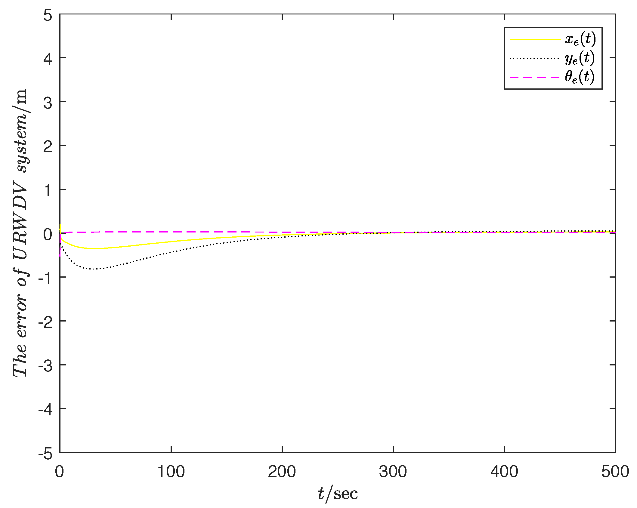
In this example, the two−dimensional helix is used to simulate the circular downhill path of a spiral winding mountain highway. The tracking results are verified using the designed controller. Given the target trajectory of the system, the speed and heading angular velocity of the controller are designed to verify that the method in this paper can achieve the control effect of trajectory tracking. Here, the initial position of the target route is set as x r ( 0 ) = 200 m and y r ( 0 ) = 200 m. The initial target velocity is v r ( 0 ) = 0.2 m/s, the initial target heading angular velocity μ r ( 0 ) 0.2 rad/s, and the initial angle of target vehicle θ r ( 0 ) = 0.5 π . The corresponding initial state of the URWDV system is x ( 0 ) = 0.2 m, y ( 0 ) = 0.2 m, the initial angle of the URWDV system is 2 3 π , the initial speed of the target vehicle is v x ( 0 ) = 0.3 m/s, the initial angular velocity of the target vehicle is μ x ( 0 ) = 0.4 rad/s, and the parameters λ 1 , λ 2 , λ 3 , and λ 4 in the control variables are 1.4 , 1.4 , 20, and 20, respectively. The looped downhill tracking route was designed in this paper to simulate the driving control situation of the unmanned vehicle on the winding mountain road. The track of the winding mountain road is set as x r 2 ( t ) + y r 2 ( t ) = 0.08 t . The following results are obtained by simulating the trajectory tracking of the unmanned vehicle based on Matlab. Figure 2 shows the tracking error state containing the position error and heading angle error, and it can be seen that the error of control tracking becomes smaller and smaller until it converges. Figure 3 shows that the speed changes between the target system and the tracking system, and it can be seen that the speed tracking gradually reaches the ideal control target. Figure 4 shows the loop downhill tracking route. It can be seen that the system moves forward along the target track under the designed control scheme, and the control scheme is effective and feasible.
Example 2.
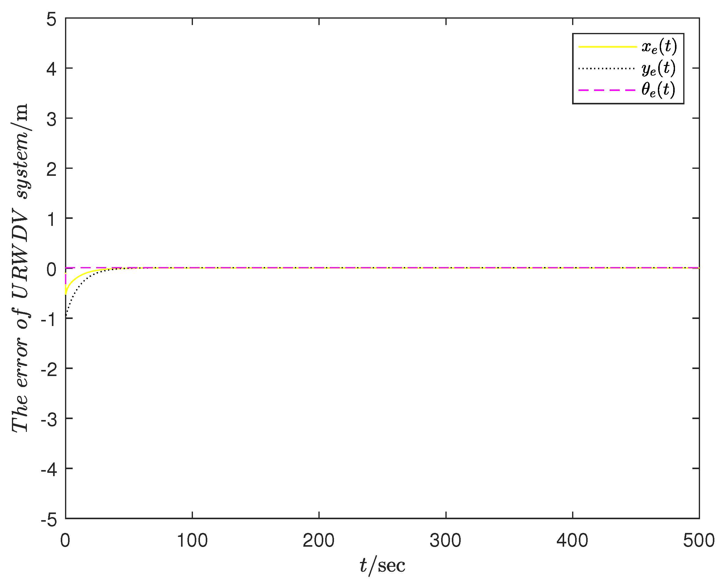
In this example, the initial position of the target route is set as x r ( 0 ) = 2 m and y r ( 0 ) = 0 m. The initial target velocity is v r ( 0 ) = 0.2 m/s, the initial target heading angular velocity μ r ( 0 ) = 0.2 rad/s, and the initial angle of target vehicle θ r ( 0 ) = 0.5 π . The corresponding initial state of the URWDV system is x ( 0 ) = 1.02 m, y ( 0 ) = 0.02 m, the initial angle of the URWDV system is 3 5 π , the initial speed of the target vehicle is v x ( 0 ) = 0.3 m/s, the initial angular velocity of the target vehicle is μ x ( 0 ) = 0.4 rad/s, and the parameters λ 1 , λ 2 , λ 3 , and λ 4 in the control variables are 1, 1, 50, and 50, respectively. The circular tracking path is designed to simulate the driving control situation of the unmanned vehicle in this example. The track of the winding mountain road is x r 2 ( t ) + y r 2 ( t ) = 4 . By simulating in Matlab, Figure 5 shows the tracking error state, and it can be seen that the error of control tracking becomes smaller and smaller until it converges. The red dashed line in Figure 6 shows the circular tracking result. It can be seen that the system moves forward along the target track under the designed control scheme, and the control scheme is effective and feasible.
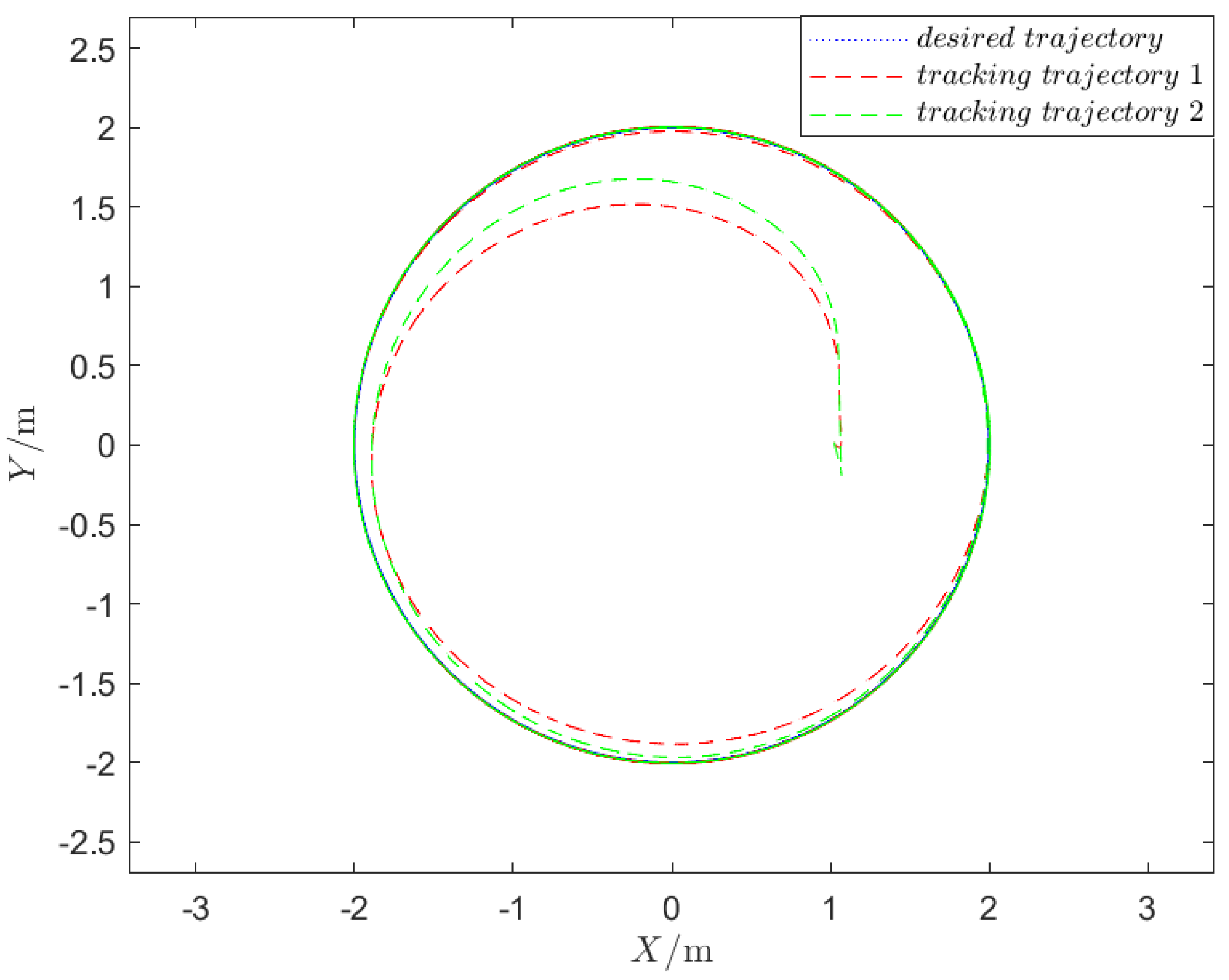
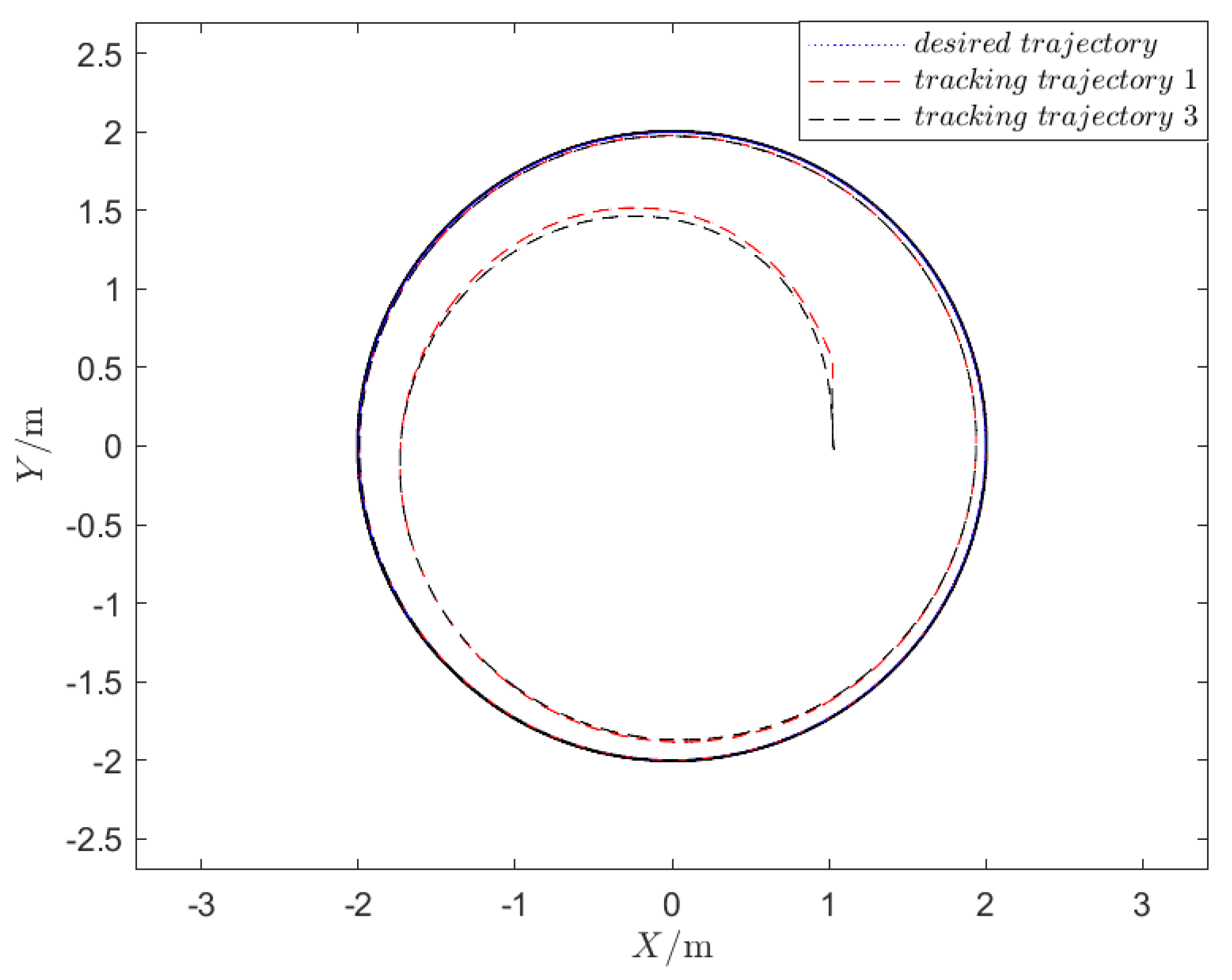
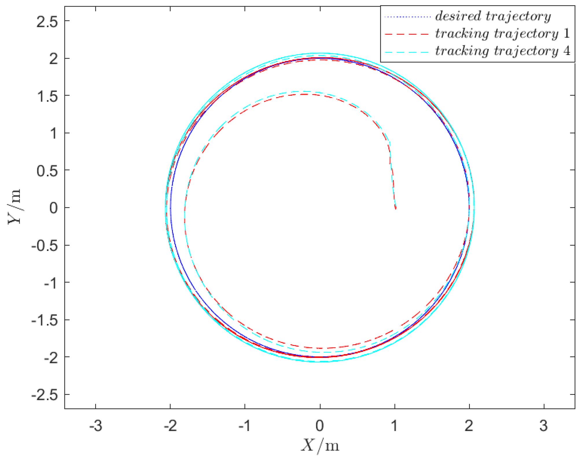
Here are given four cases of control parameters, λ 1 , λ 2 , λ 3 , and λ 4 , as shown in Table 2. Other parameters are the same as those simulation parameters mentioned in Example 2. Moreover, the corresponding final tracking trajectories with such tracking control parameters are shown in Figure 6, Figure 7 and Figure 8. As described in Remark 1, λ 1 and λ 2 adjust the position in the X direction. From Figure 6, it can be seen that the trajectory tracking ability is enhanced as λ 1 and λ 2 increase. Then, the position adjustment tends to be closer to the target, which means that the convergence speed becomes faster. λ 3 adjusts the position in the Y direction. From Figure 7, it can be observed that the trajectory tracking ability is also enhanced as λ 3 increases. For λ 4 , a decrease in the value of λ 4 means a worse heading angular ability, which is illustrated in Figure 8 by the adjustment of λ 4 . In practical engineering, the control parameters λ 1 , λ 2 , λ 3 , and λ 4 can be adjusted according to actual needs based on their control function.
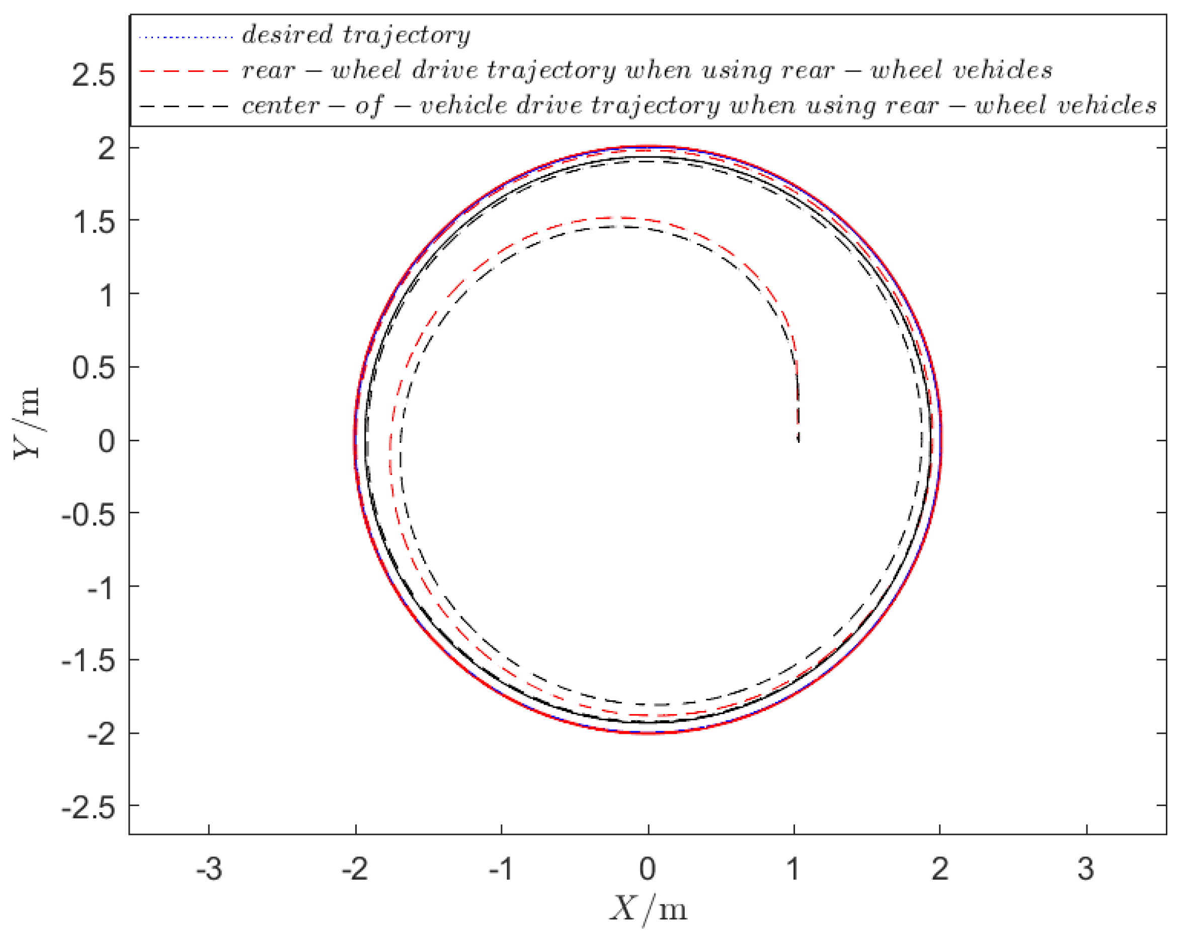
We have compared the unmanned vehicle system with rear-wheel drive that is proposed by this paper and center-of-vehicle drive that is studied in [21] when using rear-wheel vehicles. The parameters are selected as λ 1 = 1 , λ 2 = 1 , λ 3 = 50 , and λ 4 = 50 . The different tracking trajectories in Figure 9 are obtained. The blue dotted line represents the desired trajectory. The red dashed line shows the trajectory obtained using rear-wheel drive, which converges to the desired green line. The black dashed line corresponds to the trajectory obtained using center-of-vehicle drive. Moreover, it can be seen that there is a certain deviation between the black trajectory tracking and the desired trajectory due to the error of the driving force. This indicates that it is problematic to still use the center-drive unmanned system when the driving force is on the rear wheel, so it is necessary to propose a control method based on a rear-wheel drive unmanned vehicle, which is a superior part of our proposed method.

4. Discussion

The URWDV system is a typical multi-input multi-output dynamic system, and constructing the motion control method for this system is crucial for achieving trajectory tracking of the URWDV. Therefore, this paper mainly studies the trajectory tracking control problem of the URWDV system. In view of the local stability characteristics brought about by the control law designed in the past based on linearization ideas, this paper introduces virtual feedback variables based on the stability theory, simplifies the controller design using intermediate virtual control variables and partial Lyapunov functions, making the design process simple, flexible, and easy to implement with an intuitive stability analysis, and verifies the effectiveness of the control method through URWDV system trajectory tracking experiments. The parameters selected for the controller are the velocity and heading angular velocity of the URWDV, indicating that the controller has certain engineering application prospects. Compared with other controllers, the URWDV system can determine the current posture by using its initial position and motion speed under any initial error, and adjust the posture error of the system to 0 through the controller. From the simulation results above, it can be seen that the controller designed in this paper can track circular trajectories and spiral trajectories smoothly and quickly. Naturally, the designed control scheme can also enable the unmanned vehicle to successfully track diverse trajectory routes. The controller designed in this paper can be quickly converged to the desired trajectory, and after a period of time, the error curve tends to 0, demonstrating a certain anti-interference ability.

5. Conclusions

The present study investigates the problem of achieving synchronized tracking of dynamic systems in unmanned vehicles, using the Lyapunov theory. The rear-wheel-drive unmanned vehicle system is modeled based on motion equations and mathematical derivations, which involve the AVG system as well. In order to achieve the desired trajectory tracking, a novel control scheme is proposed that relies on velocity and heading angular velocity. Numerical simulations are conducted to evaluate the performance of the proposed control scheme, indicating its effectiveness for achieving synchronized tracking in unmanned vehicles. Additionally, the proposed control scheme has potential for practical applications in various fields, including logistics and transportation.

Author Contributions

Conceptualization, C.Z. and K.S.; methodology, C.Z. and K.S.; software, K.S. and C.Z.; validation, K.S.; writing-original draft, C.Z. and J.X.; writing-review & editing, C.Z., K.S. and J.X.; visualization, C.Z.; supervision, Y.T. and J.X.; funding acquisition, C.Z. All authors have read and agreed to the published version of the manuscript.

Funding

Our work in this paper was supported by the Guangdong Basic and Applied Basic Research Foundation (2021A1515110946), the Natural Science Foundation of Sichuan Province (2022NSFSC1822), the Program of Science and Technology of Sichuan Province of China (2021ZYD0012, 2022NSFSC0532), the Key R&D Projects of Sichuan Provincial Department of Science and Technology (2023YFG0287), and the Sichuan Natural Science Youth Fund Project (2023NSFSC1366).

Institutional Review Board Statement

Not applicable.

Informed Consent Statement

Not applicable.

Data Availability Statement

The data presented in this study are available on request from the corresponding author.

Conflicts of Interest

We have no conflict of interest with any individual or organization regarding this paper.

References

  1. Mantel, R.J.; Landeweerd, H. Design and operational control of an AGV system. Int. J. Prod. Econ. 1995, 41, 257–266. [Google Scholar] [CrossRef] [Green Version]
  2. Farahvash, P.; Boucher, T.O. A multi-agent architecture for control of AGV systems. Robot. Comput. Integr. Manuf. 2004, 20, 473–483. [Google Scholar] [CrossRef]
  3. Sun, H.; Zong, G.; Cui, J.; Shi, K. Fixed-time sliding mode output feedback tracking control for autonomous underwater vehicle with prescribed performance constraint. Ocean. Eng. 2022, 1, 247. [Google Scholar] [CrossRef]
  4. Luo, Z.; Tang, Y.Q.; Li, D.; Wang, L.J. AGV rectifying method based on optimal deviation path. Chin. J. Sci. Instrum. 2017, 38, 853–860. [Google Scholar]
  5. Zheng, K.; Tang, D.; Gu, W.; Dai, M. Distributed control of multi-AGV system based on regional control model. Prod. Eng. 2013, 7, 433–441. [Google Scholar] [CrossRef]
  6. Li, Q.; Udding, J.T.; Pogromsky, A.Y. Modeling and control of the AGV system in an automated container terminal. Stud. Surf. Sci. Catal. 2010, 110, 711–720. [Google Scholar]
  7. Zheng, B.K.; Lai, Y.Z.; Feng, Y.E. Design and implementation of the magnetic navigation AGV control system. Autom. Instrum. 2014, 29, 6–10. [Google Scholar]
  8. Maxwell, W.L.; Muckstadt, J.A. Design of Automated Guided Vehicle Systems. IIE Trans. 1982, 14, 114–124. [Google Scholar] [CrossRef]
  9. Shi, L.; Li, W.; Shi, M.; Shi, K.; Cheng, Y. Opinion Polarization Over Signed Social Networks with Quasi Structural Balance. IEEE Trans. Autom. Control 2023. early access. [Google Scholar] [CrossRef]
  10. Zhang, T.; Li, Q.; Zhang, C.S.; Liang, H.W.; Li, P.; Wang, T.M.; Li, S.; Zhu, Y.L.; Wu, C. Current trends in the development of intelligent unmanned autonomous systems. Front. Inf. Technol. Electron. Eng. 2017, 18, 68–85. [Google Scholar] [CrossRef] [Green Version]
  11. Shi, L.; Liu, Q.; Shao, J.; Cheng, Y.; Zheng, W. A Cooperation-Competition Evolutionary Dynamic Model Over Signed Networks. IEEE Trans. Autom. Control 2023. early acess. [Google Scholar] [CrossRef]
  12. Sujit, P.B.; Saripalli, S.; Sousa, J.B. Unmanned aerial vehicle path following: A survey and analysis of algorithms for fixed-wing unmanned aerial vehicles. IEEE Control Syst. Mag. 2014, 34, 42–59. [Google Scholar]
  13. Benaoumeur, I.; Laredj, B.; Reda, H.; Zoubir, A.F. Backstepping Approach for Autonomous Mobile Robot Trajectory Tracking. Indones. J. Electr. Eng. Comput. Sci. 2016, 2, 478–485. [Google Scholar] [CrossRef]
  14. Shi, L.; Cheng, Y.; Shao, J.; Sheng, H.; Liu, Q. Cucker-Smale flocking over cooperation-competition networks. Automatica 2022, 135, 109988. [Google Scholar] [CrossRef]
  15. He, H.; Liu, Z.; Zhu, L.; Liu, X. Dynamic Coordinated Shifting Control of Automated Mechanical Transmissions without a Clutch in a Plug-In Hybrid Electric Vehicle. Energies 2012, 5, 3094–3109. [Google Scholar] [CrossRef] [Green Version]
  16. Shi, L.; Zheng, W.X.; Shao, J.; Chen, Y.H. Sub/super-stochastic matrix with applications to bipartite tracking control over signed networks. SIAM J. Control Optim. 2021, 59, 4563–4589. [Google Scholar] [CrossRef]
  17. Mu, X.; Yan, S. Adaptive Leader-Following Consensus Tracking Control of Multiple UAVs Subject to Deception Attacks. Processes 2022, 10, 757. [Google Scholar] [CrossRef]
  18. Shi, L.; Cheng, Y.; Shao, J.; Zhang, X. Collective Behavior of Multileader Multiagent Systems with Random Interactions Over Signed Digraphs. IEEE Trans. Control Netw. Syst. 2021, 8, 1394–1405. [Google Scholar] [CrossRef]
  19. Han, S.; Zhong, Q.; Wang, Y.; Shi, K.; Zhong, S. Nonfragile consensus of nonlinear multiagent systems with intrinsic delays via aperiodic memory sampled-data control. Int. J. Robust Nonlinear Control 2022, 9, 32. [Google Scholar] [CrossRef]
  20. Zhang, K.; Su, R.; Zhang, H.; Tian, Y. Adaptive Resilient Event-Triggered Control Design of Autonomous Vehicles with an Iterative Single Critic Learning Framework. IEEE Trans. Neural Networks Learn. Syst. 2021, 32, 5502–5511. [Google Scholar] [CrossRef]
  21. Shang, J.; Zhang, J.; Li, C. Trajectory tracking control of AGV based on time-varying state feedback. EURASIP J. Wirel. Commun. Netw. 2021, 2021, 162. [Google Scholar] [CrossRef]
  22. Liu, X.; Chen, T. Synchronization of complex networks via aperiodically intermittent pinning control. IEEE Trans. Autom. Control 2015, 60, 3316–3321. [Google Scholar] [CrossRef]
  23. Fiori, S.; Cervigni, I.; Ippoliti, M.; Menotta, C. Synchronization of dynamical systems on Riemannian manifolds by an extended PID-type control theory: Numerical evaluation. Discret. Contin. Dyn. Syst.-B 2022, 27, 7373–7408. [Google Scholar] [CrossRef]
  24. Zhao, C.; Cao, J.; Shi, K.; Tang, Y.; Zhong, S.; Alsaadi, F.E. Improved Nonfragile Sampled-Data Event-Triggered Control for the Exponential Synchronization of Delayed Complex Dynamical Networks. Mathmetics 2022, 10, 3504. [Google Scholar] [CrossRef]
  25. Kesen, S.E.; Baykoç, O.F. Simulation of automated guided vehicle (AGV) systems based on just-in-time (JIT) philosophy in a job-shop environment. Simul. Model. Pract. Theory 2007, 15, 272–284. [Google Scholar] [CrossRef]
  26. Ullrich, G. Automated Guided Vehicle Systems: A Primer with Practical Applications; Springer: Berlin/Heidelberg, Germany, 2014; pp. 1–14. [Google Scholar]
  27. Kanayama, Y.; Kimura, Y.; Miyazaki, F.; Noguchi, T. A stable tracking control method for an autonomous mobile robot. In Proceedings of the IEEE International Conference on Robotics and Automation, Cincinnati, OH, USA, 13–18 May 1990; Volume 20, pp. 384–389. [Google Scholar]
  28. Lu, Y.M.; Ma, Y.T.; Hou, X. Trajectory tracking control for 4wd vehicles using MPC and adaptive fuzzy control. In Proceedings of the 36th Chinese Control Conference (CCC), Dalian, China, 26–28 July 2017; Volume 26, pp. 9367–9372. [Google Scholar]
  29. Pratama, P.S.; Gulakari, A.V.; Setiawan, Y.D.; Kim, D.H.; Kim, S.B. Trajectory Tracking and Fault Detection Algorithm for Automatic Guided Vehicle Based on Multiple Positioning Modules. Int. J. Control Autom. Syst. 2016, 14, 400–410. [Google Scholar] [CrossRef]
  30. Tayade, S.; Rost, P.; Maeder, A. Error Convergence Analysis and Stability of a Cloud Control AGV. arXiv 2021, arXiv:2102.05385. [Google Scholar]
  31. Aguirre, A.A. Remote Control and Motion Coordination of Mobile Robots. Ph.D. Thesis, Technische Universiteit Eindhoven, Eindhoven, The Netherlands, 2011. [Google Scholar]
  32. Ma, G.; Ghasemi, M.; Song, X. Integrated powertrain energy management and vehicle coordination for multiple connected hybrid electric vehicles. IEEE Trans. Veh. Technol. 2017, 67, 2893–2899. [Google Scholar] [CrossRef]
  33. Li, B.H.; Liu, Y.; Zhang, A.M.; Wang, W.H.; Wan, S. A Survey on Blocking Technology of Entity Resolution. J. Comput. Sci. Technol. 2020, 35, 769–793. [Google Scholar] [CrossRef]
  34. Zhang, J.; Chen, Q.; Sun, J.; Tian, L.; Zuo, C. On a universal solution to the transport-of-intensity equation. Opt. Lett. 2020, 45, 3649–3652. [Google Scholar] [CrossRef]
  35. Jiang, B.; Li, J.; Yang, S. An improved sliding mode approach for trajectory following control of nonholonomic mobile AGV. Sci. Rep. 2022, 12, 17763. [Google Scholar] [CrossRef]
  36. Azzabi, A.; Nouri, K. Design of a robust tracking controller for a nonholonomic mobile robot based on sliding mode with adaptive gain. Int. J. Adv. Robot. Syst. 2021, 18, 1729881420987082. [Google Scholar] [CrossRef]
  37. Lin, L.; Wu, P.; He, B.; Chen, Y.; Zheng, J.; Peng, X. The sliding mode control approach design for nonholonomic mobile robots based on non-negative piecewise predefined-time control law. IET Control Theory Appl. 2021, 15, 1286–1296. [Google Scholar] [CrossRef]
  38. Ling, Y.; Wu, J.; Lyu, Z.; Xiong, P. Backstepping controller for laser ray tracking of a target mobile robot. Meas. Control 2020, 53, 1540–1547. [Google Scholar] [CrossRef]
  39. Ye, H.; Wang, S. Trajectory tracking control for nonholonomic wheeled mobile robots with external disturbances and parameter uncertainties. Int. J. Control Autom. Syst. 2020, 18, 3015–3022. [Google Scholar] [CrossRef]
  40. Bai, J.; Du, J.; Li, T.; Chen, Y. Trajectory tracking control for wheeled mobile robots with kinematic parameter uncertainty. Int. J. Control Autom. Syst. 2022, 20, 1632–1639. [Google Scholar] [CrossRef]
  41. Mai, T.A.; Dang, T.S.; Duong, D.T.; Le, V.C.; Banerjee, S. A combined backstepping and adaptive fuzzy PID approach for trajectory tracking of autonomous mobile robots. J. Braz. Soc. Mech. Sci. Eng. 2021, 43, 156. [Google Scholar] [CrossRef]
  42. Han, Y.; Cheng, Y.; Xu, G. Trajectory tracking control of AGV based on sliding mode control with the improved reaching law. IEEE Access 2019, 7, 20748–20755. [Google Scholar] [CrossRef]
  43. Jiang, J.; Astolfi, A. Shared-control for a rear-wheel drive car: Dynamic environments and disturbance rejection. IEEE Trans. Hum. Mach. Syst. 2017, 47, 723–734. [Google Scholar] [CrossRef] [Green Version]
  44. Mutoh, N.; Kazama, T.; Takita, K. Driving characteristics of an electric vehicle system with independently driven front and rear wheels. IEEE Trans. Ind. Electron. 2006, 53, 803–813. [Google Scholar] [CrossRef]
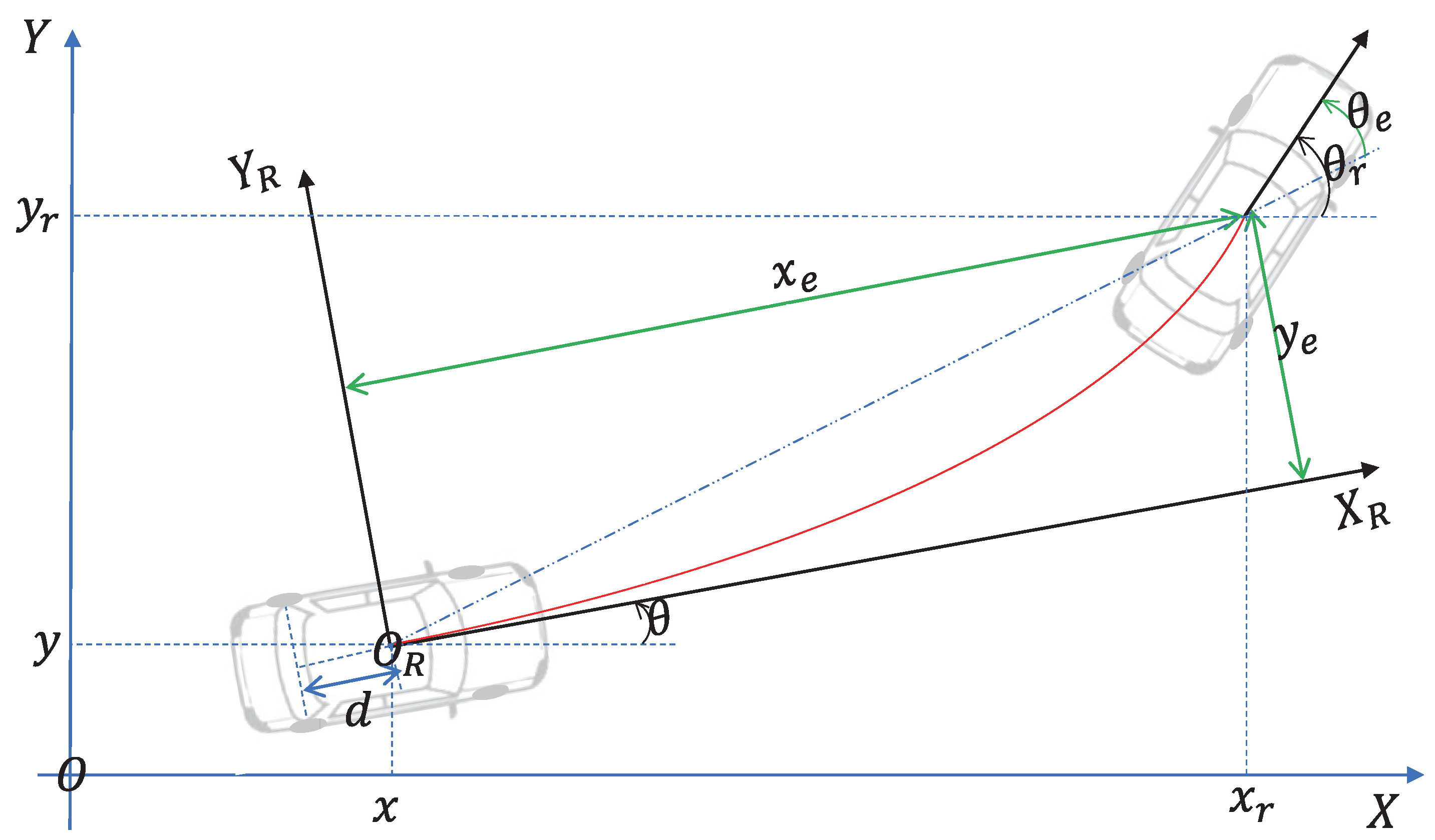
Figure 1. Parameters and analytic diagram of URWDV.
Drones 07 00417 g001
Figure 2. The error of the URWDV system in Example 1.
Drones 07 00417 g002
Figure 3. The velocities of tracking result by synchronized tracking control in Example 1.
Drones 07 00417 g003
Figure 4. Tracking trajectory by synchronized tracking control in Example 1.
Drones 07 00417 g004
Figure 5. The error of the URWDV system in Example 2.
Drones 07 00417 g005
Figure 6. Tracking trajectory by synchronized tracking control in Example 2.
Drones 07 00417 g006
Figure 7. Tracking trajectory by synchronized tracking control in Example 2.
Drones 07 00417 g007
Figure 8. Tracking trajectory by synchronized tracking control in Example 2.
Drones 07 00417 g008
Figure 9. Comparison of trajectory tracking under different driving modes in Example 2.
Drones 07 00417 g009
Table 1. Comparative performance and features of tracking control of unmaned vehicles.
Rear-Wheel DriveCenter-of-Vehicle DriveBackstepping MethodLyapunov-Based Analysis
[32]YesYesNoNo
[20]YesYesNoNo
[35]NoYesNoYes
[36]NoYesNoYes
[37]NoYesNoYes
[38]NoYesYesYes
[39]NoYesYesYes
[40]NoYesYesYes
[41]NoYesYesNo
[42]NoYesNoYes
[43]NoYesNoYes
[44]YesYesNoNo
Our methodYesYesYesYes
Table 2. Four cases of control parameters for trajectory tracking.
Four Cases λ 1 λ 2 λ 3 λ 4
tracking trajectory 1115050
tracking trajectory 2335050
tracking trajectory 3111050
tracking trajectory 4115020
Disclaimer/Publisher’s Note: The statements, opinions and data contained in all publications are solely those of the individual author(s) and contributor(s) and not of MDPI and/or the editor(s). MDPI and/or the editor(s) disclaim responsibility for any injury to people or property resulting from any ideas, methods, instructions or products referred to in the content.